Speed Synchronous Control of Multiple Permanent Magnet Synchronous Motors Based on an Improved Cross-Coupling Structure


School of Electrical and Information Engineering, Tianjin University, Tianjin 300072, China
*
Author to whom correspondence should be addressed.
Energies 2018, 11(2), 282; https://doi.org/10.3390/en11020282
Submission received: 1 January 2018
/
Revised: 19 January 2018
/
Accepted: 23 January 2018
/
Published: 24 January 2018
Abstract
:Regarding the shortcomings of the cross-coupling control structure during the start-up of a multi-motor with load—namely, a large synchronization error and a long start-up time—this paper proposes a fuzzy self-adjusting cross-coupling control structure. This structure combines a fuzzy self-adjusting filter and an advanced synchronization compensator. The fuzzy self-adjusting filter adjusts the “softened speed”, a newly established concept, so that each motor follows the trajectory of the softened speed during start-up, thus effectively reducing the synchronization error of the starting process. The advanced synchronization compensator is added to shorten the adjusting time of the motors. In addition, this paper analyzes the synchronization performance of the structure when the steady state is interrupted by a sudden step of load. Finally, this paper establishes an experimental platform for a synchronous speed control system for a permanent magnet synchronous motor, and verifies the effectiveness of the proposed structure and the correctness of the theoretical analysis through performing experiments.
1. Introduction
With the development of modern industry, the synchronous control of multi-motors has been widely used in robotics, electric vehicles, steel rolling, papermaking, and other fields [1,2,3,4,5,6,7,8]. Shortening the start-up time and improving the synchronization performance of multi-motors are of both theoretical and practical significance for enhancing the control accuracy and stability of the system [9,10,11,12,13,14,15].
A virtual line-shafting control and a cross-coupling control structure are usually adopted in the traditional multi-motor synchronous control [16,17,18,19,20]. Anderson R.G. et al. [21] proposed the concept of “electronic virtual line-shafting”. The sum of electromagnetic torque from the servo motors was taken as the load torque of the main motor, which can reduce the synchronization error caused by the starting delay, but the starting time was longer. Therefore, it’s not applicable to the occasions that require a high starting performance. Then, Koren Y. et al. presented a cross-coupling control structure, where the speed difference between two motors was taken as a feedback. This structure could better reflect the load changes of each motor [22], so, it exhibits good synchronization performance in the steady-state operation. In order to improve the synchronization performance and tracking performance of a multi-motor system under sudden changes of load during steady operation, Gu X., Zhang H. and Liu G. et al. presented [23,24,25] many advanced control methods, such as a neural network, sliding mode control, and internal model control are applied to the cross-coupling control. However, the above methods still have the shortcomings of a large synchronization error and a long starting time during the start-up of a loaded multi-motor system.
Aiming at the aforementioned problems, this paper presents a fuzzy self-adjusting cross-coupling control structure that combines a fuzzy self-adjusting filter with an advanced synchronization compensator. The concept of “softened speed” is put forward in this new structure. The fuzzy controller adjusts the softened coefficient of each motor smoothly according to the load torque and the actual given speed; therefore, the softened speed can be adjusted automatically. In this way, motors can follow the trajectory of the softened speed during the start-up of a multi-motor with load, and thus reduce the synchronization error. At the same time, the advanced synchronization compensator is put forward to utilize the phase advance characteristic and obtain the phase advance, thus shortening the adjusting time of the motors. Finally, the experimental platform of the synchronous speed control system is established, and the effectiveness of the fuzzy self-adjusting cross-coupling control structure proposed in this paper is verified through experiments.
2. Traditional Cross-Coupling Control
The control method, which adopts speed difference as a compensation signal in multi-motor synchronous control, holds high reliability [26]. The speed difference between the two motors is taken as a compensation signal in the traditional cross-coupling control method. The compensation signal can reduce the speed error of the two motors when the motor is disturbed internally or externally [27,28]. The motion equations of a permanent magnet synchronous motor (PMSM) are taken to describe the dynamic and static performance of two motors in the cross-coupling control structure [29]:
where J is the moment of inertia of the motor; ω is the rotor angular velocity of the motor; Te is the electromagnetic torque; TL is the load torque; KT is the torque coefficient; and B is the damping coefficient.
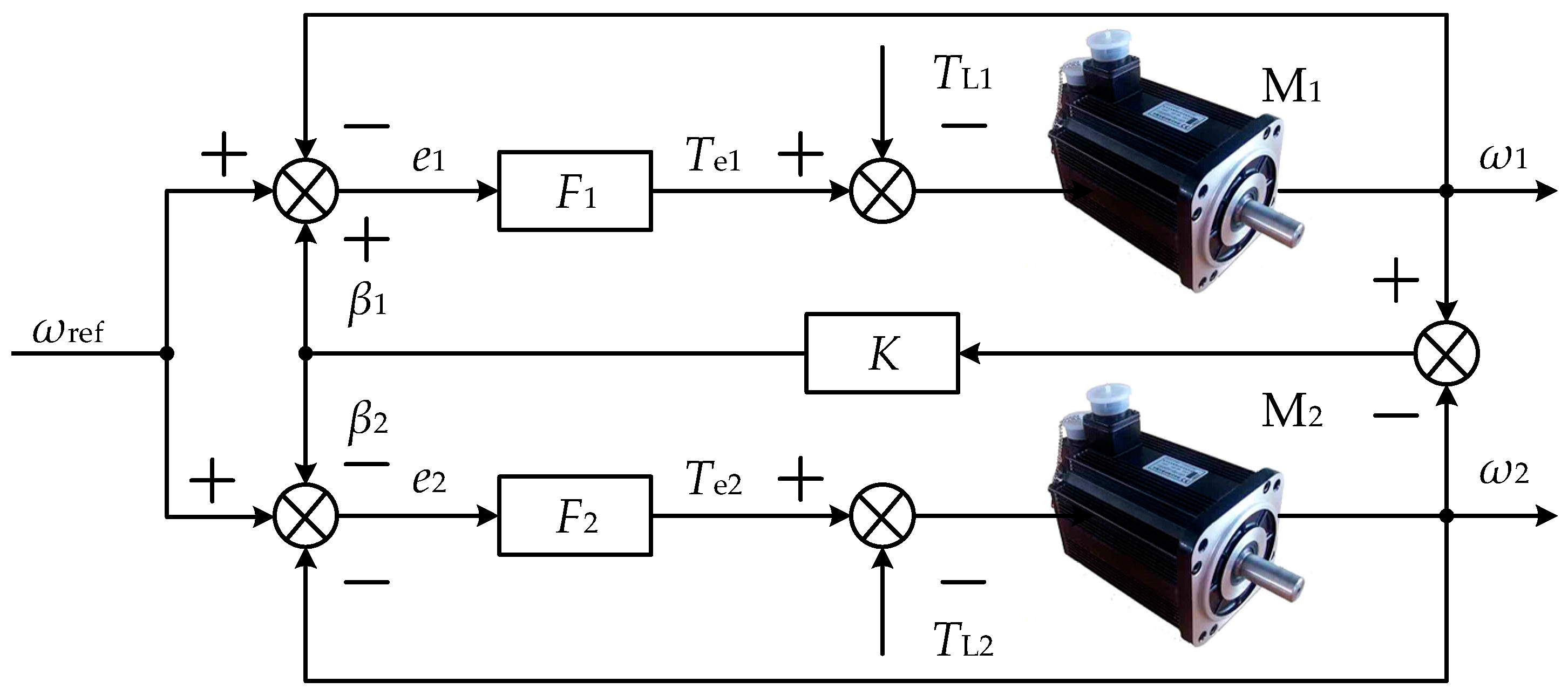
For the convenience of analysis, the motor is usually equivalent to an integral part, disregarding the delay of the current loop and speed measurement. The block diagram of the traditional cross-coupling control structure is shown in Figure 1.
In Figure 1, ωref is the given speed of two motors; TLi (i = 1, 2) is the load torque of the ith motor; ωi is the output speed of the ith motor; and the equivalent transfer function of the ith motor Mi is given by:
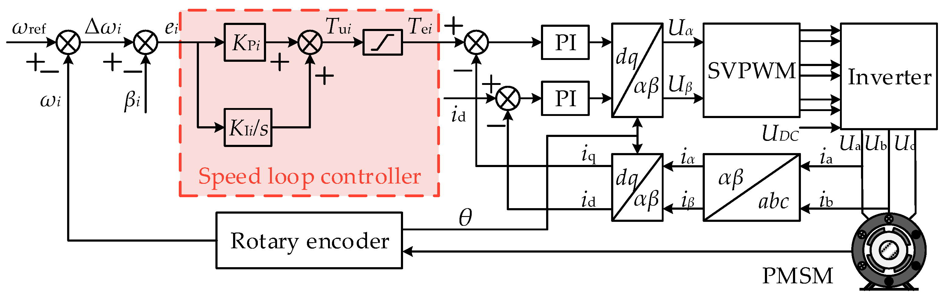
where Fi is the ith motor speed loop controller; the structure is shown in Figure 2.
In Figure 2, Tui is the amplitude-unlimited electromagnetic torque output of the ith motor; Tei is the amplitude-limited electromagnetic torque output of the ith motor; and ei is the input of speed loop controller of the ith motor, which can be expressed as:
where Δωi is the tracking error of the ith motor; and βi is the compensation value. βi is given by:
where Kij is the synchronous compensation coefficient between two motors.
Taking the ith motor as an example, the speed loop controller Fi can be expressed as:
In Equation (5), the proportional coefficient KPi and the integral coefficient KIi need to be adjusted according to the dynamic and static performance of the speed loop. KPi and KIi are shown in Equation (6).
where fc and ζ are the bandwidth and damping coefficient of the speed loop, respectively. Each motor is set by the above method [30], hence:
Which means that each motor has the same open-loop transfer function, independently of the moment of inertia.
There are some shortcomings in a traditional cross-coupling control structure during the start-up of a multi-motor with load:
- In Figure 2, the tracking error Δωi is much larger than the compensation value βi, according to Equation (3), and ei is very large during the start-up of a multi-motor with load, thus making the amplitude-unlimited output of electromagnetic torque Tui much larger than the saturation value. However, the output of the speed loop controller generally contains a limiting part because of the system’s safety requirements. The output Tei of the speed loop controller will be saturated for a period of time, during which the compensation value does not work, eventually leading to a larger synchronization error.
- When the speed fluctuation of the system is large, the fixed gain compensation can’t be adjusted according to the disturbance of each motor in real time; this results in a longer adjusting time.
3. Fuzzy Self-Adjusting Cross-Coupling Control
Aiming at the problem of the cross-coupling control structure in the start-up of a multi-motor system with load, this paper adds a fuzzy self-adjusting control module, and introduces the advanced synchronous compensator into the traditional cross-coupling control structure. The block diagram of the two motors is shown in Figure 3.
The fuzzy self-adjusting control module and advanced synchronization compensator module are discussed as follows.
3.1. Fuzzy Self-Adjusting Control Module
Since the tracking error is much larger than the compensation value in the cross-coupling control structure during the start-up of a multi-motor with load, Tei is in saturation for a long time, thus resulting in a greater synchronization error. In a fuzzy self-adjusting cross-coupling control structure, the softened speed ω*ref is adjusted by the fuzzy self-adjusting control module, which makes it converge to ωref smoothly. This makes the tracking error close to the output of the synchronous compensator in the starting process, thus reducing the influence of the saturation of the limiting part of the speed loop controller on the synchronization error. The fuzzy self-adjusting control module is shown in Figure 4.
In Figure 4, the output α of the fuzzy controller is defined as the softened coefficient, and ε is defined as the steady state control coefficient. In this paper, ε = 1. Namely:
The mode selector is used to switch between modes. It divides the fuzzy controller into two operating modes based on ωmax. Mode 1: when ωmax < 0.98ωref, it is considered that the motor is in a fast start stage. The fuzzy controller and the filter work simultaneously, so that each motor follows the trajectory of the softened speed to reduce the synchronization error; Mode 2: when ωmax ≥ 0.98ωref, it is considered that the motor gradually enters into the steady state. In this case, only the filter is activated, thereby improving the dynamic response of the system.
In order to make the softened speed transition to the set value at a certain response speed smoothly, the following filter link is usually taken [31,32]:
where 0 < α <1.
Selecting ωref = 1000 r/min, the load torque of two motors during the start-up are TL1 = 5 N·m, and TL2 = 0, respectively. Take α (0, 1) as input; the output are the adjusting time ts of Motor 1 and the synchronization error Δω between the two motors. When the parameters, such as the given speed and load torque remain unchanged, the influence of the change of the coefficient α on the synchronization error and adjusting time of the system can be described by several rounds of simulation. As can be seen in Figure 5, the synchronization error and adjusting time of each motor during start-up are affected by the softened coefficient α. When α is too small, the synchronization error between the two motors is smaller, but the adjusting time is longer; on the contrary, when α is too large, the adjusting time of the two motors is smaller, but the synchronization error is larger. In practice, the synchronous start-up of two motors needs to balance between the synchronization error and the adjusting time so as to achieve the best control effect. In addition, curves Δω and ts with respect to α will be different when the given speed or load torque changes. In order to make a multi-motor synchronous control system achieve the best control effect, this paper adopts a fuzzy controller to adjust the output of α automatically.
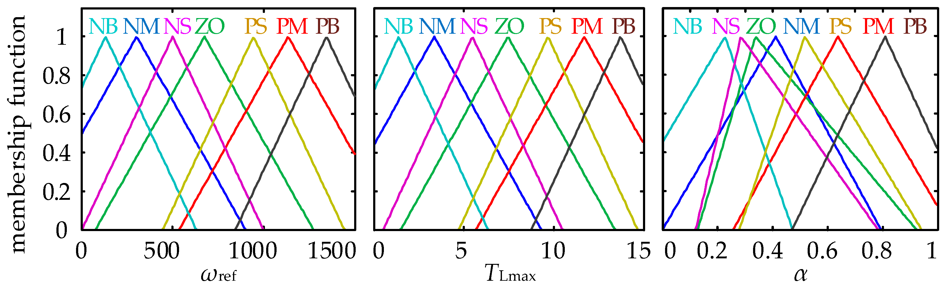
The inputs of fuzzy controller are ωref and TLmax, and the output is α. In order to improve the sensitivity of the control, the input and output are quantized by normalized quantization factors [33,34]. The quantized inputs ωref and TLmax, and the output α, belong to seven fuzzy subsets in the universe of discourse, namely, {NB NM NS O PS PM PB}. NB is Negative Big; NM is Negative Medium; NS is Negative Small; O is Zero; PS is Positive Small; PM is Positive Medium; and PB is Positive Big.
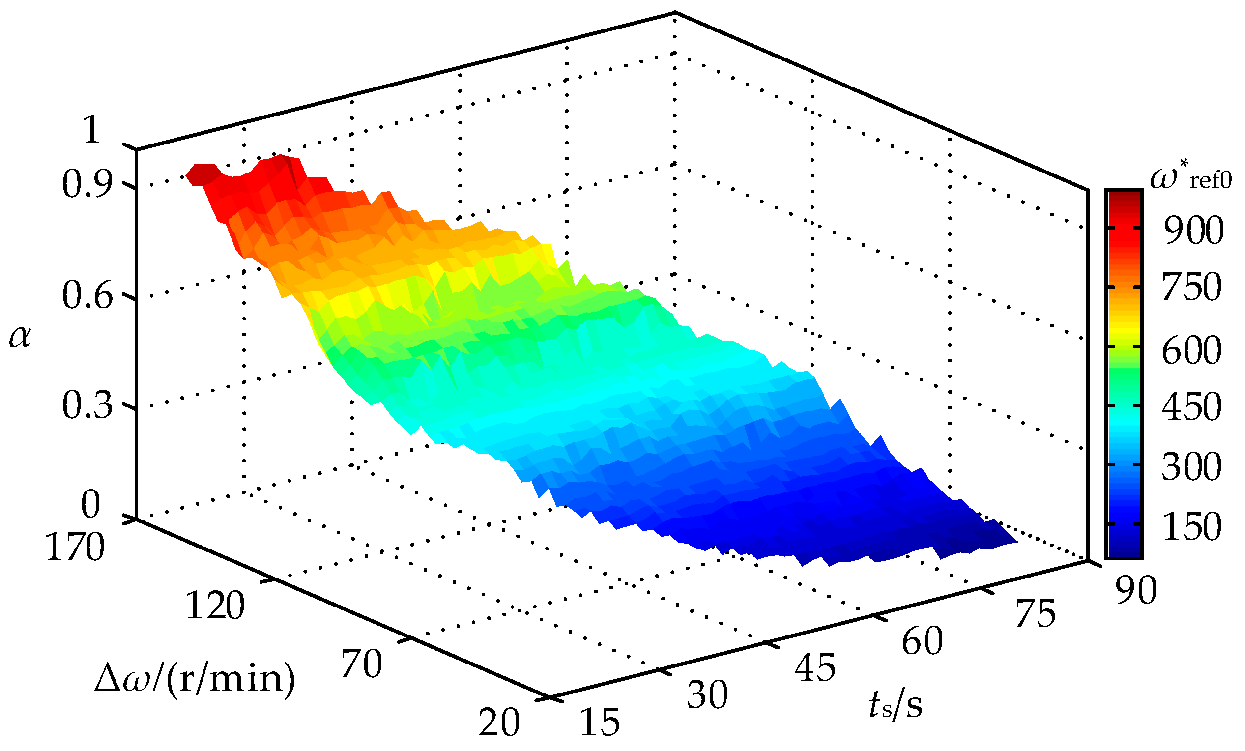
Forty-nine fuzzy rules can be obtained from Mamdani reasoning [35,36], as shown in Table 1. Corresponding input and output membership functions are shown in Figure 6. The three-dimensional rendering of the input and output relations of the fuzzy controller obtained by the fuzzy rules is shown in Figure 7. As can be seen in the figure, the output α of the fuzzy controller decreases, while ωref or TLmax increases.
Six combinations are formed by setting ωref as 1000 r/min, 800 r/min, and 500 r/min; TL1 as 5 N·m and 15 N·m; and TL2 as 0, respectively. The fuzzy control was used to obtain the value of α and the curve of ω*ref. Figure 8 shows the softened speed under different operating conditions, and Table 2 shows the different operating conditions that correspond to Figure 8.
① ③, ② ④, and ⑤ ⑥ correspond to three operating conditions of the same given speed but different load torques; while ① ② ⑤ and ③ ④ ⑥ correspond to the operating conditions of the same load torque but different speeds. The variation of softened speed ω*ref can be roughly divided into two stages: the rising stage, and the steady stage, in which the motor speed increases rapidly at the initial stage of starting, and the fuzzy self-adjusting module automatically adjusts the softened speed so that it is on the rise. Then ei decreases, thus shortening the time of Tei in saturation. Then, ω*ref remains unchanged after the motor gradually enters the steady state. First, comparing the working conditions ① ③, the load torque of the working condition ① is larger, so the adjusting time of the output speed of the motor is longer. Therefore, the time required for the softened speed of the fuzzy self-adjusting control to reach the maximum value increases correspondingly, so that t1 > t3, making each motor follow the softened speed trajectory in a better manner. Then, comparing the working conditions ① ②, because the given speed of ① is greater than that of ②, the period in which ω*ref is on the rise under condition ① is longer, thus t1 > t2, ensuring that each motor can better follow the trajectory of the softened speed. According to Equation (9), since ωmax = 0 at the initial starting time, the output value α of the fuzzy controller is different when the given speed is different. From Equation (9), it can be seen that the values of the softened speeds of two motors are different at the initial starting time. Therefore, by adjusting the softened coefficient according to different operating conditions, the fuzzy self-adjusting control module can make each motor better follow the trajectory of the softened speed. Furthermore, the input of the speed loop controller is reduced, so that the time of electromagnetic torque in the saturation state is shortened. Finally, the purpose of reducing the synchronization error during the start-up is achieved.
3.2. The Advanced Synchronization Compensator
When a load of the motor changes greatly, the fixed gain synchronous compensator will give rise to an excessive fluctuation of speed, and it takes a long time for the fluctuation to be smoothed out. For each motor, the speed fluctuation of any other motor can be regarded as a time-varying interference. In order to eliminate the effect of interference on the output characteristic of the system, corrective control is employed to further improve the adjusting time. The synchronous compensator with anticipatory control is shown in Figure 9.
In Figure 9, K is the synchronization compensation coefficient; and Fg is the correction controller. In order to accelerate the system’s dynamic response [37], this paper introduces the classic advanced correction, namely:
where T is advanced time constant; and η is attenuation factor and η > 1.
The advanced compensation controller compensates the output speed of its own according to the disturbance level of the other motor. The amount of advancement needed by the system is obtained by using the phase advance characteristic of Fg, thus increasing the cut-off frequency, and finally reducing the influence of the disturbance.
The following analysis indicates the influence of the speed fluctuation of the second motor on the first motor in the fuzzy self-adjusting cross-coupling control structure. As shown in Figure 3, the output speed ω2 of the second motor is taken as the input, and the output speed ω1 of the first motor is taken as the output. The transfer function in this case is:
A Bode diagram of phase-frequency characteristics and amplitude-frequency characteristics when K = 2 is shown in Figure 10. In order to facilitate the comparison with the traditional cross-coupling control structure, the transfer function of the traditional cross-coupling structure is deduced as:
Figure 10 also shows the Bode diagram of the amplitude-frequency characteristics and phase-frequency characteristics of the traditional structure. As can be seen from the figure, the fuzzy self-adjusting cross-coupling control structure increases the cut-off frequency and improves the system’s dynamic response compared with the traditional cross-coupling control structure. The phase margin increases, and the stability of the system is improved.
4. Performance Analysis of Fuzzy Self-adjusting Cross-Coupling Control
4.1. Synchronization Performance Analysis during the Start-Up of Motors with Load
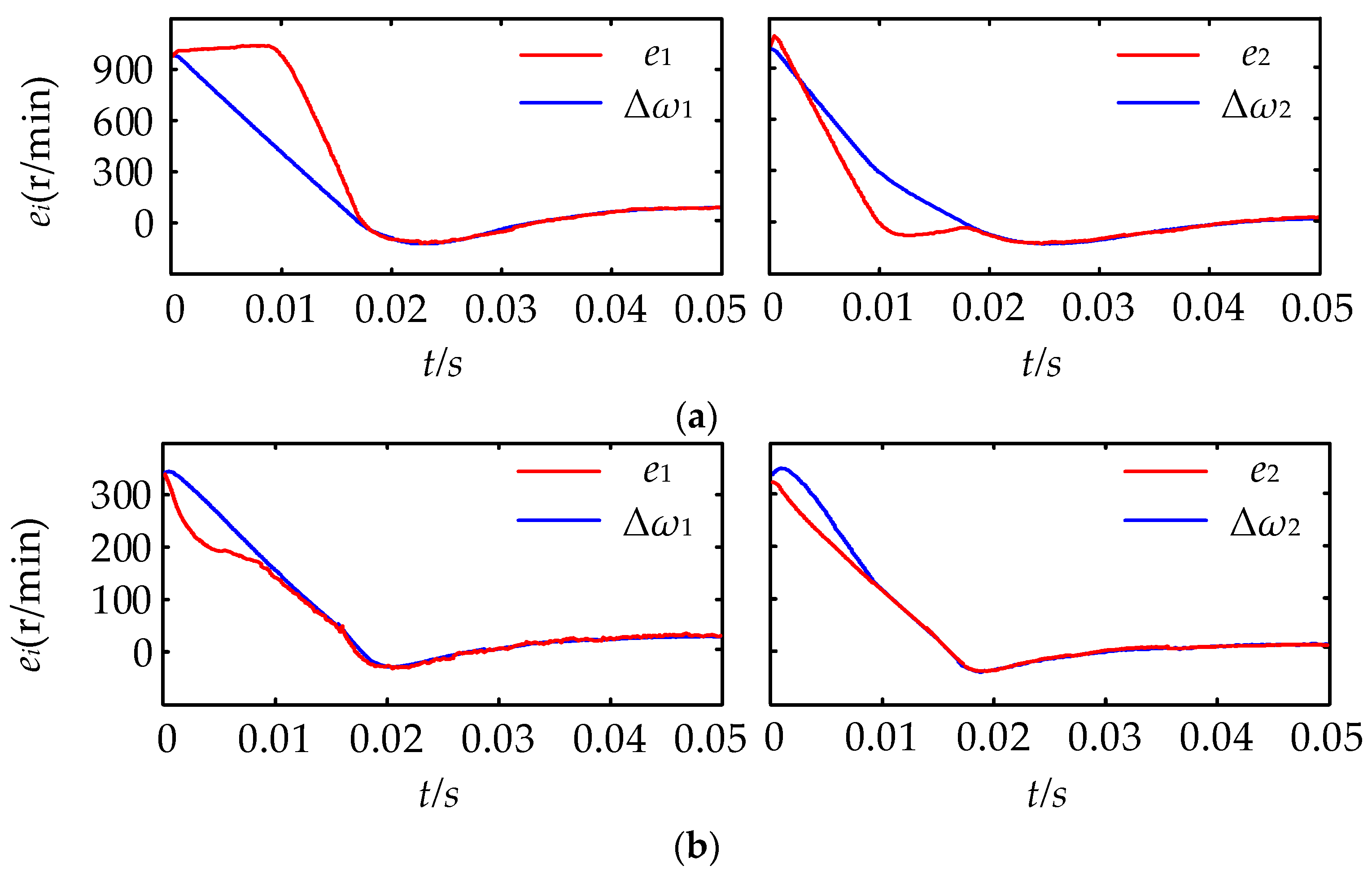
To simplify the analysis, it is assumed that the load torque of the first motor is TL1 > 0, and the second motor starts without load. Therefore, for the output speeds of the first motor and the second, it holds that ω1 < ω2. In Figure 11, ei is the input of the ith (i = 1,2) motor’s speed loop controller; and Δωi is the tracking error of the ith motor. Setting the rated torque as TN, then, the saturation value equals 1.2TN.
It can be seen from Figure 11a that in the traditional cross-coupling control structure, for the load motor, it holds that e1 > Δω1, indicating that the compensation value β1 < 0 and e1 during the start-up of the motors with load is large. As a result, the output Tu1 of the controller corresponding to the input e1 is far greater than the saturation value, so Te1 is equal to 1.2 TN. The compensation value basically does not work. For the initial value of the no-load motor during starting, it holds that e2 > Δω2; the compensation value still does not work. Only when β2 increases to a certain value does the compensation value begin to play a compensatory role.
In Figure 11b, the load motor satisfies e1 < Δω1, indicating that the compensation value β1 > 0, and the advanced synchronous compensator compensates for the speed. The advanced synchronous compensator of the no-load motor also compensates for the speed.
Regarding the early stages during the start-up, the controller of each motor is working in the nonlinear region. Ignoring the integral action of the controller, the input ei (i = 1, 2) of the speed loop controller with load in the starting process is:
Similarly, the input of the speed loop controller in the traditional cross-coupling control structure is:
Comparing Equation (13) with (14), it should be noted that in the starting process of the fuzzy self-adjusting cross-coupling control structure, because 0 < α <1 and η > 1, the coefficient before the first term Δωi of Equation (13) is reduced; that is, the tracking proportional coefficient decreases. Further, the coefficient before the second Δω increases; that is, the synchronization proportional coefficient increases.
In summary, in the multi-motor starting process, compared with the traditional cross-coupling control structure, the tracking error of the fuzzy self-adjusting cross-coupling control structure decreases, and the synchronous compensator output increases simultaneously. Hence, the input of the speed loop controller decreases. Therefore, the time for Tu1 to be saturated is shortened, and the synchronization error is thus reduced.
When the controller of each motor works in the linear region, the difference of accelerations between two motors in the fuzzy self-adjusting cross-coupling control structure is:
From Equation (15), it should be noted that the acceleration difference between two motors is independent of α; that is, changing the softened coefficient α will not influence the synchronization performance of the system in the working area of the linear zone.
4.2. Synchronization Performance Analysis of Steady State with Sudden Changes of Load
In this section, the synchronization performance of the steady state with sudden changes of loads in a fuzzy self-adjusting cross-coupling control structure is analyzed. The ith motor output speed is:
Derived from Equation (16), the synchronization error between two motors can be expressed as:
Similarly, the synchronization error of two motors in the traditional cross-coupling control structure is:
From the above analysis, it should be noted that η > 1, therefore, 1 − Fg < 0. Compared with the traditional cross-coupling control structure, the Δω of a fuzzy self-adjusting cross-coupling control structure decreases obviously; that is, the synchronization error between two motors in steady state with sudden changes of load decreases.
5. Experiments and Analysis
5.1. Experimental System and Parameter Selection
To verify the effectiveness of the fuzzy self-adjusting cross-coupling control structure, the PMSM speed control system experimental platform is constructed, as shown in Figure 12. The hardware system is mainly composed of two PMSMs. The PMSMs used in this paper are surface-mounted. One motor is connected to the magnetic powder brake, and the other is connected to the load motor, which is interlinked over a resistance box. The controlling circuit features mainly include a main control panel, power circuit, drive circuit, voltage, current sensors, and so on. The DSP chip TMS320F28335 produced by TI is used as the core in the main control panel. The power devices use Mitsubishi’s IPM module PS21867, and the switching frequency is 5 kHz. The parameters of two motors are shown in Table 3.
5.2. Performance Comparison of Two Structures During the Start-Up of Motors with Load
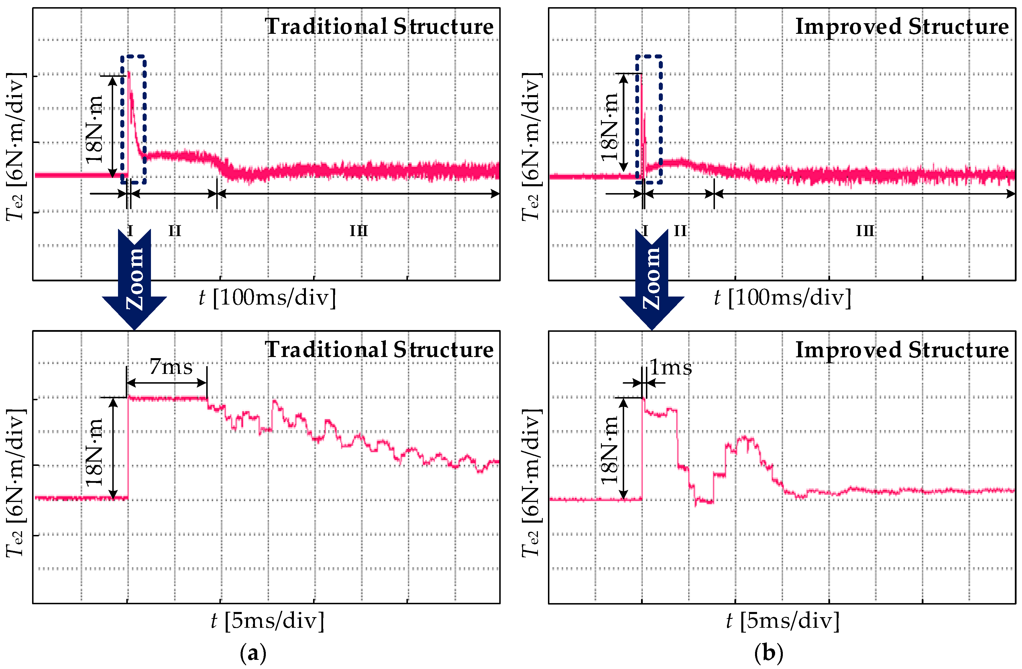
The experimental parameters are set as follows: initially, the two motors start at a given speed of 500 r/min. Motor 1 is connected to the magnetic brake, and Motor 2 is connected to a load motor. The torque of the magnetic brake is 8 N·m, and the load motor is no-load. The rated torque is TN, and the saturation value of the speed loop controller is set as 1.2 TN. A performance comparison of the synchronization error and output speed between the two structures during the start-up of motors with load are shown in Figure 13 and Figure 14. In the figure, ts is the adjusting time, and tp is the peak time. The electromagnetic torque outputs of the first and second motor during the start-up are shown in Figure 15 and Figure 16, respectively. Performances of the traditional cross-coupling control structure (abbreviated as traditional structure hereafter) are shown in Figure 13a of every figures below, and performances of the fuzzy self-adjusting cross-coupling control structure (abbreviated as improved structure hereafter) are shown in Figure 13b of every figures below.
As can be seen from Figure 13, the maximum synchronization error of the improved structure reduces from 157 r/min to 70 r/min, which is a reduction of 55% compared with the traditional structure. Meanwhile, the dynamic response of synchronization error increases by 43%. In Figure 14, the adjusting time reduces from 360 ms to 275 ms, which is a 23% reduction; and the peak time reduces by 4.8%.
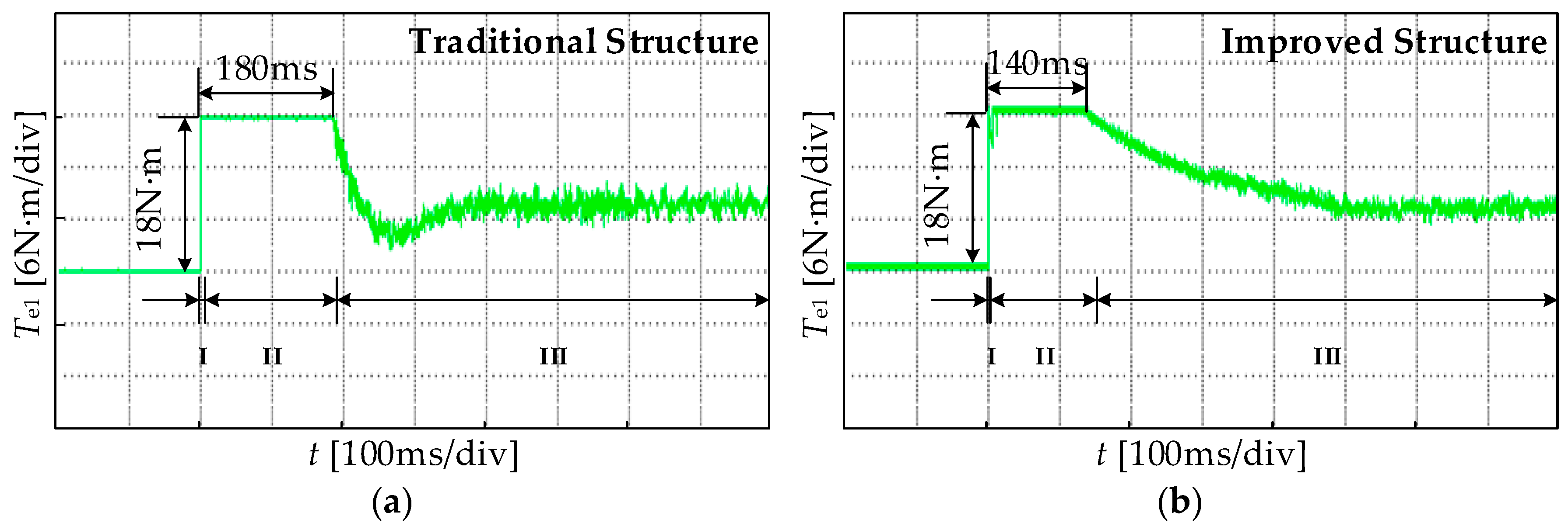
From the above experiments, it should be noted that the starting process of the motor is divided into three stages. In Figure 15a and Figure 16a, the electromagnetic torque outputs of the two motors are saturated within 7 ms in the first stage, and the synchronous compensator does not work at all. In the second stage, the electromagnetic torque output of Motor 1 is still in saturation. As a result of the compensation value, Motor 2 enters the linear region, and its working time is 173 ms. In the third phase, both of the motors run in the linear working region under the action of compensation. In Figure 15b and Figure 16b, namely, in the improved structure, the working time of the first stage is shortened by 6 ms. Since the control period of the system is 0.4 ms, it enters the linear work area 15 times in advance; in stage II, the electromagnetic torque output of Motor 1 stays in saturation for 139 ms, which a 19% reduction, and is why the synchronization error significantly reduces.
5.3. Performance Comparison of Two Structures in Steady State with Sudden Changes of Load
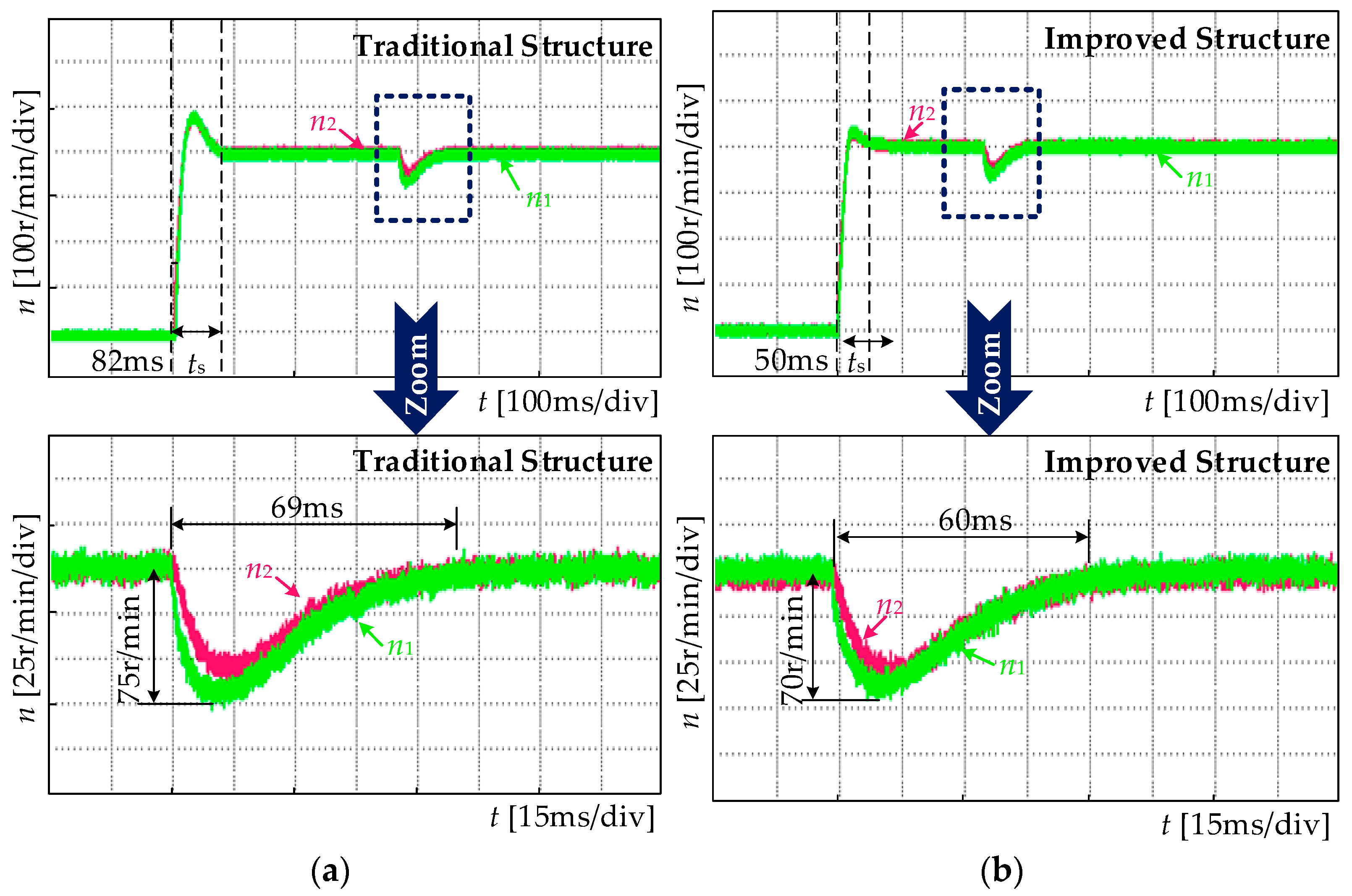
The given speed is 400 r/min, and the two motors both start without load. A sudden load of 10 N·m is applied to Motor 1 in the stable operation. The output speed of each motor and synchronization error of the two structures are shown in Figure 17 and Figure 18, respectively.
As can be seen from Figure 17, the maximum synchronous error between two motors reduces from 128 r/min to 95 r/min, which is a decrease of 25.7%, compared with the traditional structure. The convergence speed of synchronization error increased by 49%.
In Figure 18, the adjusting time of the speed is shortened by 39%, the tracking error is reduced from 74 r/min to 70 r/min—almost unchanged—and the response time of the tracking error reduces from 69 ms to 60 ms.
To summarize, the improved structure proposed in this paper not only improves the synchronization performance and dynamic response between two motors in the starting process, it also improves the synchronization performance of motors when the steady state is interrupted by a sudden change of load.
6. Conclusions
Aiming at the shortcomings of the cross-coupling control structure, which has a large synchronization error and a long starting time in the multi-motor system during the start-up of motors with load, this paper presents a new coupling control structure with a fuzzy self-adjusting filter and an advanced synchronization compensator.
- The structure adopts the mode selector to switch between working modes of the fuzzy controller. It automatically adjusts the softened coefficient according to different given speeds and maximum load torques, and then adjusts the softened speed so that each motor follows the trajectory of the softened speed in the starting process. These adjustments effectively reduce the synchronization error during the start-up of motors with load. At the same time, the advanced synchronization compensator is put forward to improve the system’s dynamic response.
- The synchronization performance of the fuzzy self-adjusting cross-coupling control structure under the steady state with a sudden change of load is analyzed. The experimental results show that the structure proposed in this paper can improve the system synchronization performance and dynamic response both in the starting process, and in the steady state with a sudden change of load.
Acknowledgments
This work is supported by The National Natural Science Foundation of China (No. 51777135), The Key Project in the Science & Technology Pillar Program of Tianjin (No. 16YFZCSF00580).
Author Contributions
Wei Chen, Jiaojiao Liang and Tingna Shi put forward the idea and designed the simulation and the experiments; Jiaojiao Liang performed the simulation and the experiments; all authors analyzed the results; all authors contributed to the writing of the paper; Jiaojiao Liang and Tingna Shi reviewed and edited the manuscript.
Conflicts of Interest
The authors declare no conflict of interest.
References
- Chen, W.; Wu, Y.; Du, R.; Chen, Q.; Wu, X. Speed tracking and synchronization of a dual-motor system via second order sliding mode control. Math. Prob. Eng. 2013, 2013. [Google Scholar] [CrossRef]
- Jiang, C.; Chau, K.T.; Liu, C.; Lee, C.H.T. An overview of resonant circuits for wireless power transfer. Energies 2017, 10, 894. [Google Scholar] [CrossRef]
- Liu, M.; Gu, F.; Huang, J.; Wang, C.; Cao, M. Integration design and optimization control of a dynamic vibration absorber for electric wheels with in-wheel motor. Energies 2017, 10, 2069. [Google Scholar] [CrossRef]
- Li, X.; Chau, K.T.; Wang, Y. Modeling of a field-modulated permanent-magnet machine. Energies 2016, 9, 1078. [Google Scholar] [CrossRef]
- Wang, Q.; He, F. The synchronous control of multi-motor drive control system with floating compensation. In Proceedings of the 2016 12th World Congress on Intelligent Control and Automation (WCICA), Guilin, China, 12–15 June 2016. [Google Scholar] [CrossRef]
- Zhang, C.; Jia, L.; Xiao, Y.; He, J.; Xu, C. Virtual line-shafting control for permanent magnet synchronous motor systems using sliding-mode observer. IET Control Theory Appl. 2015, 9, 456–464. [Google Scholar] [CrossRef]
- Lin, F.J.; Hung, Y.C.; Ruan, K.C. An intelligent second-order sliding-mode control for an electric power steering system using a wavelet fuzzy neural network. IEEE Trans. Fuzzy Syst. 2014, 22, 1598–1611. [Google Scholar] [CrossRef]
- Shi, T.; Liu, H.; Geng, Q.; Xia, C. Improved relative coupling control structure for multi-motor speed synchronous driving system. IET Electr. Power Appl. 2016, 10, 451–457. [Google Scholar] [CrossRef]
- Luo, Y.; Liu, C.; Yu, F.; Lee, C.H.T. Design and evaluation of an efficient three-phase four-leg voltage source inverter with reduced IGBTs. Energies 2017, 10, 530. [Google Scholar] [CrossRef]
- Liu, X.; Lin, Q.; Fu, W. Optimal design of permanent magnet arrangement in synchronous motors. Energies 2017, 10, 1700. [Google Scholar] [CrossRef]
- Liu, M.; Gu, F.; Zhang, Y. Ride comfort optimization of in-wheel-motor electric vehicles with in-wheel vibration absorbers. Energies 2017, 10, 1647. [Google Scholar] [CrossRef]
- Chen, C.S.; Chen, L.Y. Robust cross-coupling synchronous control by shaping position commands in multiaxes system. IEEE Trans. Ind. Electron. 2012, 59, 4761–4773. [Google Scholar] [CrossRef]
- Chen, S.L.; Yang, J.H. Contouring control of biaxial systems with optimal and adaptive cross coupling controller. In Proceedings of the 2015 IEEE International Conference on Automation Science and Engineering (CASE), Suzhou, China, 23–25 October 2015. [Google Scholar] [CrossRef]
- Corapsiz, M.; Erenturk, K. Trajectory tracking control and contouring performance of three dimensional CNC. IEEE Trans. Ind. Electron. 2016, 63, 2212–2220. [Google Scholar] [CrossRef]
- Li, L.; Li, W.; Li, D.; Li, J.; Fan, Y. Research on strategies and methods suppressing permanent magnet demagnetization in permanent magnet synchronous motors based on a multi-physical field and rotor multi-topology structure. Energies 2018, 11, 40. [Google Scholar] [CrossRef]
- Su, K.H.; Cheng, M.Y. Contouring accuracy improvement using cross-coupled control and position error compensator. Int. J. Mach. Tools Manuf. 2008, 48, 1444–1453. [Google Scholar] [CrossRef]
- Zhao, D.Z.; Li, C.W.; Ren, J. Speed synchronisation of multiple induction motors with adjacent cross-coupling control. IET Control Theory Appl. 2010, 4, 119–128. [Google Scholar] [CrossRef]
- Zhu, X.; Yao, B.; Tao, G.; Wang, Q.; Cao, J. Adaptive robust synchronous control of a individual metering dual-cylinder pneumatic system with composite parallel method. In Proceedings of the 2014 IEEE/ASME International Conference on Advanced Intelligent Mechatronics, Besancon, France, 8–11 July 2014. [Google Scholar] [CrossRef]
- Chen, Z.; He, J.; Zheng, Y.; Song, T.; Deng, Z. An optimized feedforward decoupling PD register control method of roll-to-roll web printing systems. IEEE Trans. Autom. Sci. Eng. 2016, 13, 274–283. [Google Scholar] [CrossRef]
- Chen, W.; Wang, D.; Geng, Q.; Xia, C. Robust adaptive cross-coupling position control of biaxial motion system. Sci. China Technol. Sci. 2015, 59, 680–688. [Google Scholar] [CrossRef]
- Anderson, R.G.; Meyer, A.J.; Valenzuela, M.A.; Lorenz, R.D. Web machine coordinated motion control via electronic line-shafting. IEEE Trans. Ind. Appl. 2001, 37, 247–254. [Google Scholar] [CrossRef]
- Koren, Y. Cross-coupled biaxial computer control for manufacturing systems. J. Dyn. Syst. Meas. Control 1980, 102, 265–272. [Google Scholar] [CrossRef]
- Gu, X.; Hu, S.; Shi, T.; Geng, Q. Multi-parameter decoupling on-line identification of permanent magnet synchronous motor based on neural network. Trans. China Electrotech. Soc. 2015, 30, 114–121. [Google Scholar] [CrossRef]
- Zhang, H.; Wang, P.; Han, B.; Cheng, J. Rotor position measuring method for magnetic levitation high speed PMSM based on fuzzy sliding mode observer. Trans. China Electrotech. Soc. 2014, 29, 148–154. [Google Scholar] [CrossRef]
- Liu, G.; Zhang, J.; Zhao, W.; Zhang, Y.; Jiang, Y. Internal model control based on support vector machines generalized inverse for two-motor variable frequency system applications. Proc. CSEE 2011, 31, 85–91. [Google Scholar] [CrossRef]
- Lee, C.H.T.; Chau, K.T.; Cao, L. Development of reliable gearless motors for electric vehicles. IEEE Trans. Magn. 2017, 53, 1–8. [Google Scholar] [CrossRef]
- Yepes, A.G.; Vidal, A.; Lopez, O.; Doval-Gandoy, J. Evaluation of techniques for cross-coupling decoupling between orthogonal axes in double synchronous reference frame current control. IEEE Trans. Ind. Electron. 2014, 61, 3527–3531. [Google Scholar] [CrossRef]
- Zhao, X.; Zhao, J. Cross-coupled complementary sliding mode control for precision direct-drive gantry system. Trans. China Electrotech. Soc. 2015, 30, 7–12. [Google Scholar] [CrossRef]
- Huang, Z.; Chen, J. Analysis and implementation of permanent magnet synchronous motor control starting process for electric vehicle. Electr. Mach. Control Appl. 2015, 42, 60–64. [Google Scholar] [CrossRef]
- Harnefors, L.; Saarakkala, S.E.; Hinkkanen, M. Speed control of electrical drives using classical control methods. In Proceedings of the 2011 IEEE Energy Conversion Congress and Exposition, Phoenix, AZ, USA, 17–22 September 2011. [Google Scholar] [CrossRef]
- Zhao, X.; Zhao, J.; Li, H. Robust tracking control for direct drive XY table based on GPC and DOB. Trans. China Electrotech. Soc. 2015, 30, 150–154. [Google Scholar] [CrossRef]
- Tian, L.; Zhao, J.; Sun, J. Sensorless control of interior permanent magnet synchronous motor in low-speed region using novel adaptive filter. Energies 2016, 9, 1084. [Google Scholar] [CrossRef]
- Li, S.; Gu, H. Fuzzy adaptive internal model control schemes for PMSM speed-regulation system. IEEE Trans. Ind. Inform. 2012, 8, 767–779. [Google Scholar] [CrossRef]
- Zhou, J.; Zhao, Z.; Zhang, C.; Li, C.; Xu, Y. A real-time accurate model and its predictive fuzzy PID controller for pumped storage unit via error compensation. Energies 2017, 11, 35. [Google Scholar] [CrossRef]
- Shiau, J.K.; Wei, Y.C.; Lee, M.Y. Fuzzy controller for a voltage-regulated solar-powered MPPT system for hybrid power system applications. Energies 2015, 8, 3292–3312. [Google Scholar] [CrossRef]
- Liu, D.; Cui, Y.; Zhao, X.; Chen, M. Fuzzy control of speed of permanent magnet synchronous motor based on backstepping control. Trans. China Electrotech. Soc. 2014, 29, 38–44. [Google Scholar] [CrossRef]
- Zhang, D.; Chen, Y.; Ai, W.; Zhou, Z. A precision fuzzy control method of permanent magnetic linear motors. Trans. China Electrotech. Soc. 2007, 22, 64–68. [Google Scholar] [CrossRef]
Figure 1.
Traditional cross-coupling control structure.

Figure 2.
Control system of double closed-loop permanent magnet synchronous motor (PMSM).

Figure 3.
Fuzzy self-adjusting cross-coupling control structure.
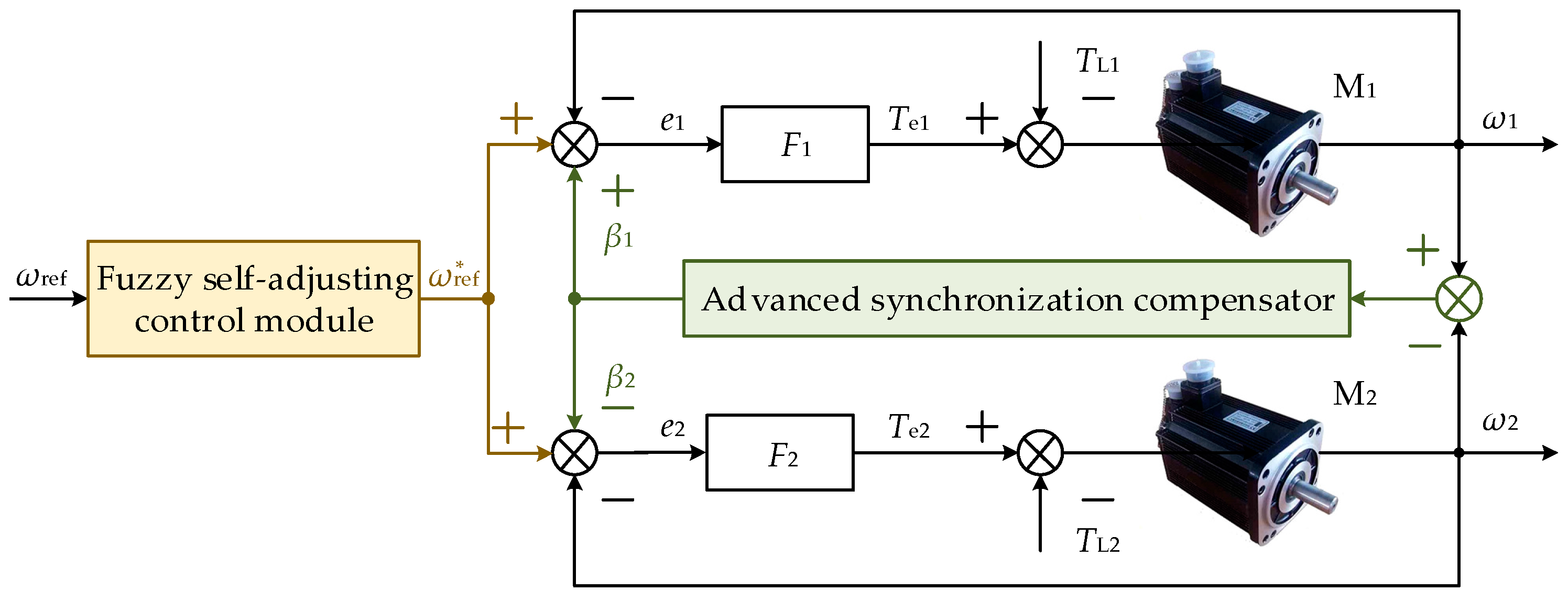
Figure 4.
Fuzzy-self-adjusting control module.
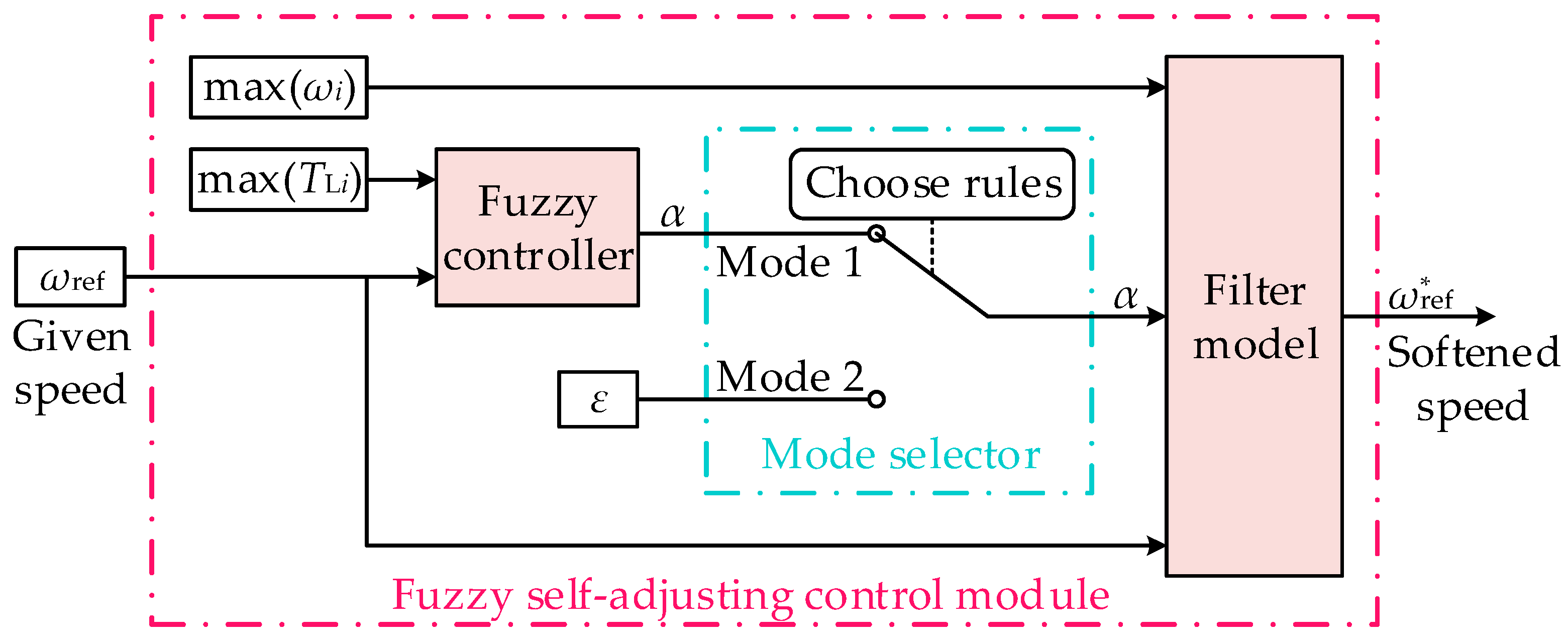
Figure 5.
The effect of α on synchronization error and the adjusting time.

Figure 6.
Fuzzy input/output membership function of the fuzzy controller.

Figure 7.
Input and output relationship of the fuzzy controller.
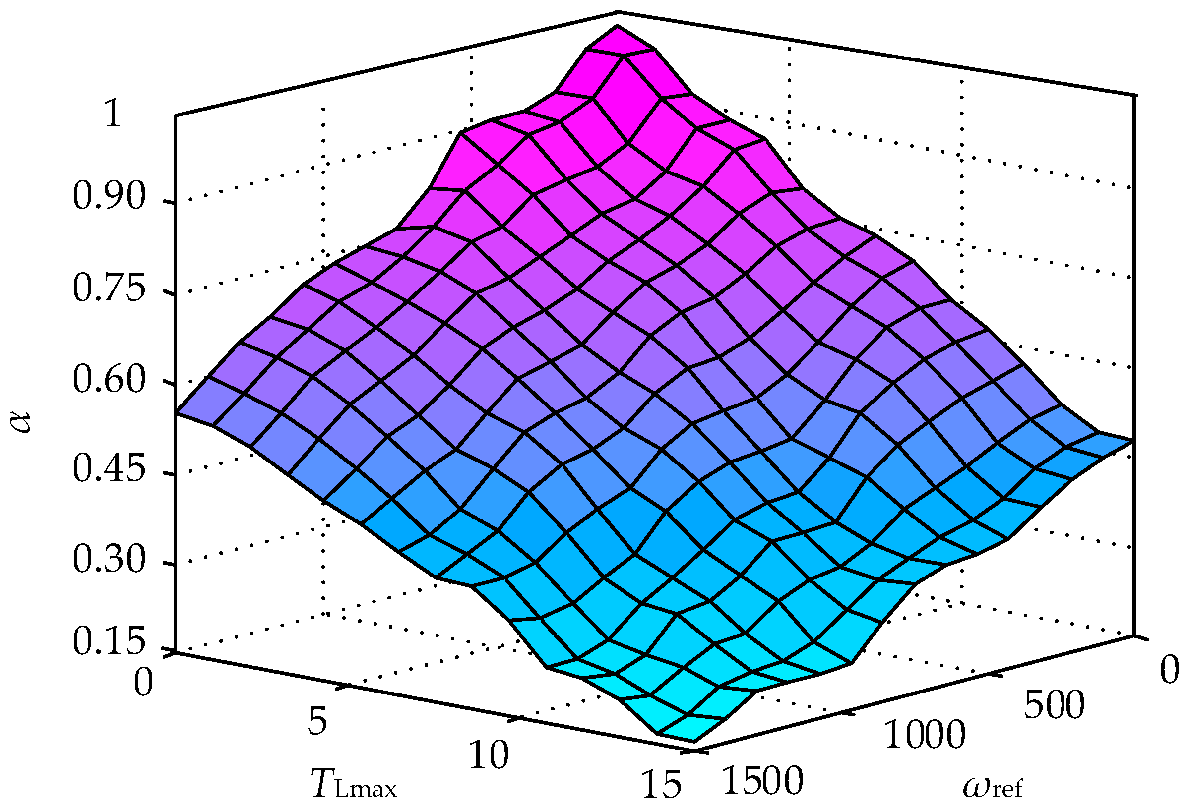
Figure 8.
Softened speed under different operating conditions.
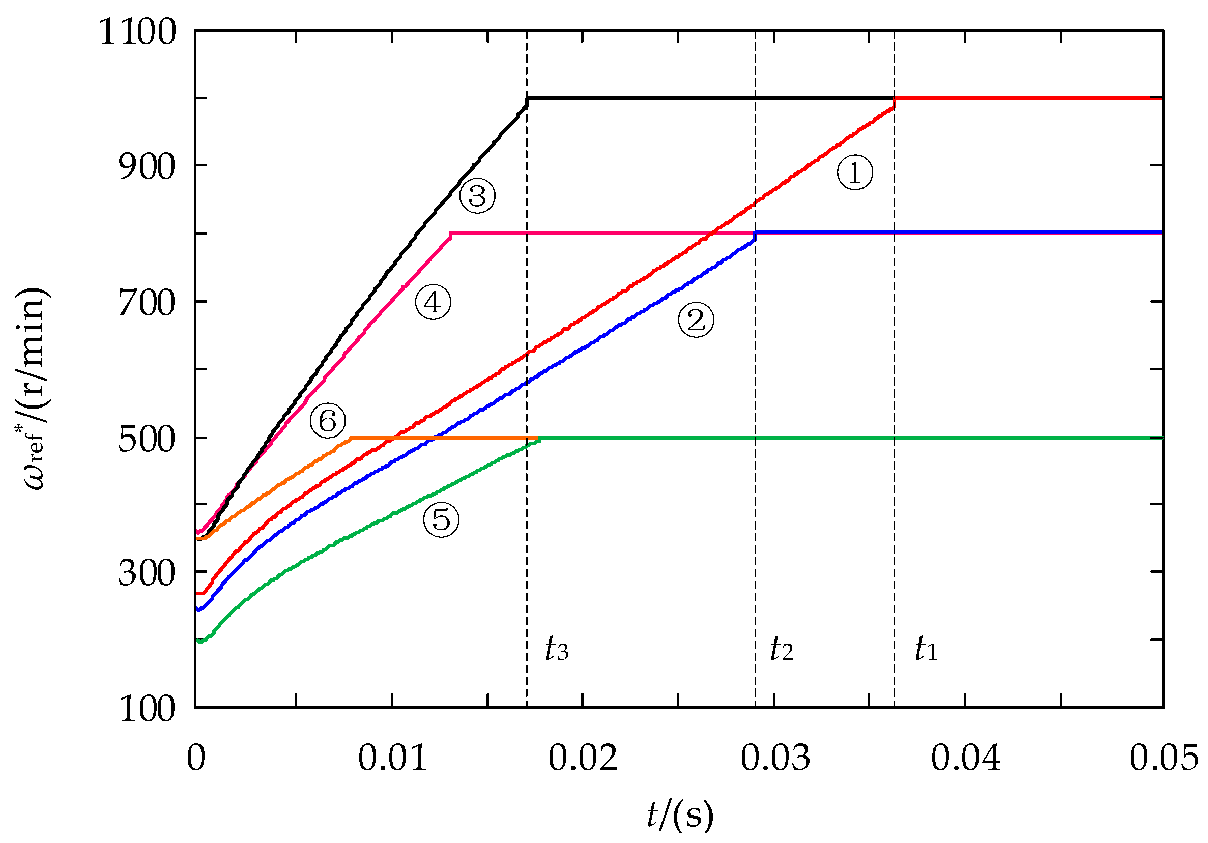
Figure 9.
Advanced synchronous compensator.

Figure 10.
Bode plots characteristic of the controlled object before and after correction.
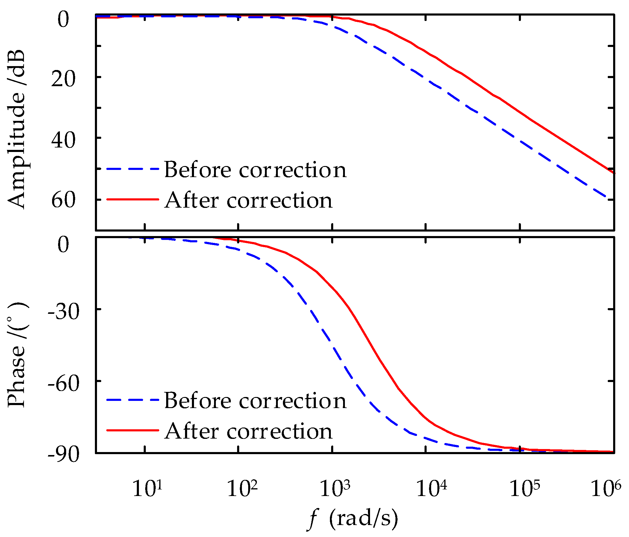
Figure 11.
Input e1 of the speed loop controller of the two structures: (a) e1 in the traditional cross-coupling control structure; (b) e1 in the fuzzy self-adjusting cross-coupling control structure.
Figure 11.
Input e1 of the speed loop controller of the two structures: (a) e1 in the traditional cross-coupling control structure; (b) e1 in the fuzzy self-adjusting cross-coupling control structure.

Figure 12.
Experiment system: (a) The experimental platform for the synchronous speed control system; (b) System of PMSMs and the magnetic powder brake.
Figure 12.
Experiment system: (a) The experimental platform for the synchronous speed control system; (b) System of PMSMs and the magnetic powder brake.
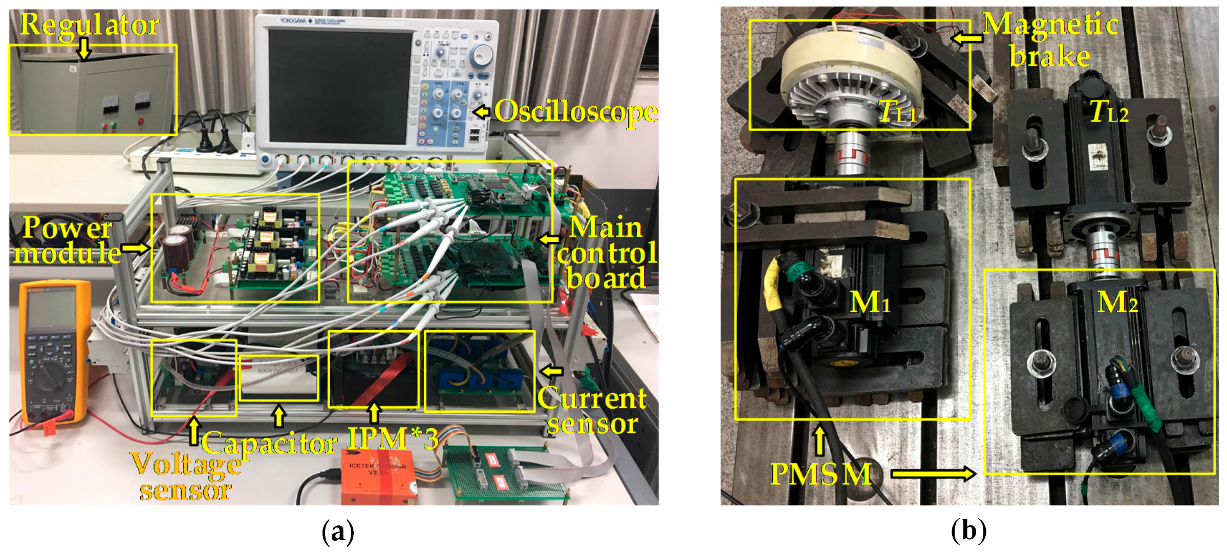
Figure 13.
Synchronization error during the start-up of motors with load: (a) Synchronization error in the traditional structure; (b) Synchronization error in the improved structure.
Figure 13.
Synchronization error during the start-up of motors with load: (a) Synchronization error in the traditional structure; (b) Synchronization error in the improved structure.
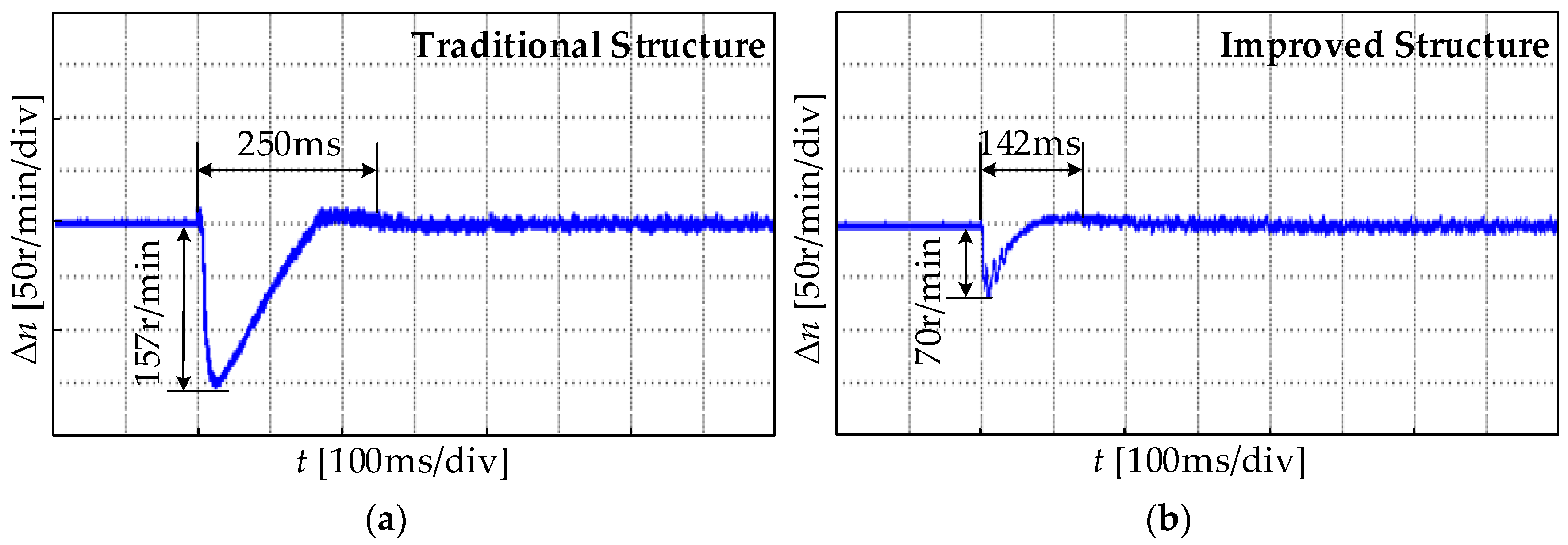
Figure 14.
Output speed during the start-up of motors with load: (a) Output speed in the traditional structure; (b) Output speed in the improved structure.
Figure 14.
Output speed during the start-up of motors with load: (a) Output speed in the traditional structure; (b) Output speed in the improved structure.
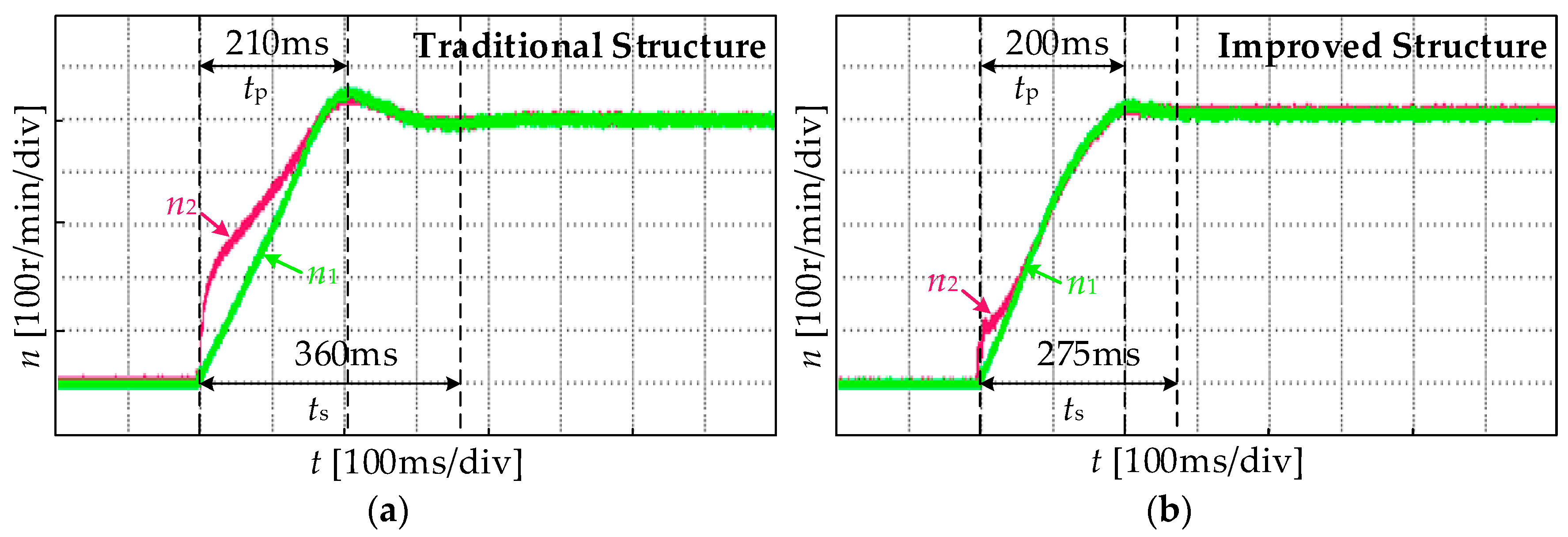
Figure 15.
Electromagnetic torque output of the first motor during the start-up of motors with load: (a) Electromagnetic torque output in the traditional structure; (b) Electromagnetic torque output in the improved structure.
Figure 15.
Electromagnetic torque output of the first motor during the start-up of motors with load: (a) Electromagnetic torque output in the traditional structure; (b) Electromagnetic torque output in the improved structure.

Figure 16.
Electromagnetic torque output of the second motor during the start-up of motors with load: (a) Electromagnetic torque output in the traditional structure; (b) Electromagnetic torque output in the improved structure.
Figure 16.
Electromagnetic torque output of the second motor during the start-up of motors with load: (a) Electromagnetic torque output in the traditional structure; (b) Electromagnetic torque output in the improved structure.

Figure 17.
Synchronization error of motors under sudden changes of a load during steady operation: (a) Synchronization error in the traditional structure; (b) Synchronization error in the improved structure.
Figure 17.
Synchronization error of motors under sudden changes of a load during steady operation: (a) Synchronization error in the traditional structure; (b) Synchronization error in the improved structure.
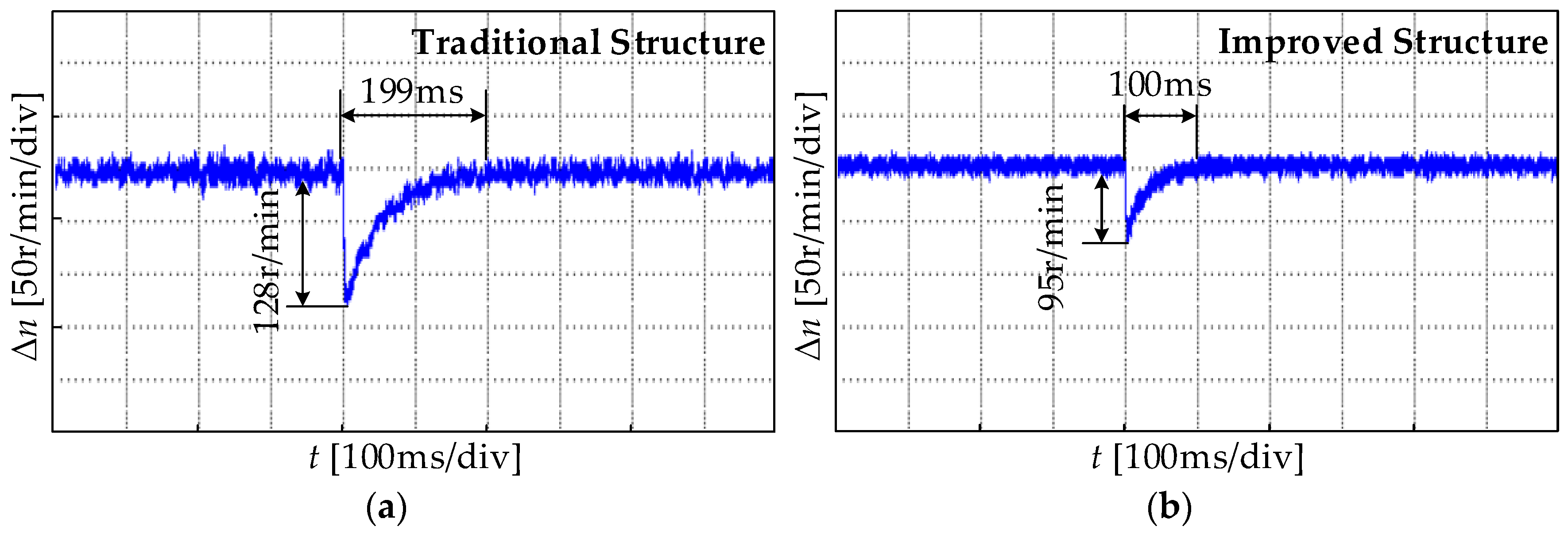
Figure 18.
Speed output of motors under sudden changes of a load during steady operation: (a) Speed output in the traditional structure; (b) Speed output in the improved structure.
Figure 18.
Speed output of motors under sudden changes of a load during steady operation: (a) Speed output in the traditional structure; (b) Speed output in the improved structure.

Table 1.
Fuzzy control rules. NB: Negative Big; NM: Negative Medium; NS: Negative Small; O: Zero; PS: Positive Small; PM: Positive Medium; PB: Positive Big.
Table 1.
Fuzzy control rules. NB: Negative Big; NM: Negative Medium; NS: Negative Small; O: Zero; PS: Positive Small; PM: Positive Medium; PB: Positive Big.
| ωref | NB | NM | NS | ZO | PS | PM | PB | ||
| α | |||||||||
| TLmax | |||||||||
| NB | PB | PB | PB | PB | PM | PS | ZO | ||
| NM | PB | PB | PM | PM | PS | ZO | ZO | ||
| NS | PB | PM | PM | PS | ZO | ZO | NS | ||
| ZO | PM | PS | PS | ZO | NS | NS | NM | ||
| PS | PS | ZO | ZO | NS | NM | NM | NB | ||
| PM | ZO | ZO | NS | NM | NM | NB | NB | ||
| PB | ZO | NS | NM | NB | NB | NB | NB | ||
Table 2.
Different operating conditions that correspond to Figure 8.
Table 2.
Different operating conditions that correspond to Figure 8.
| Condition | ① | ② | ③ | ④ | ⑤ | ⑥ | |
|---|---|---|---|---|---|---|---|
| Variate | |||||||
| ωref (r/min) | 1000 | 800 | 1000 | 800 | 500 | 500 | |
| TLmax (N·m) | 15 | 15 | 5 | 5 | 15 | 5 | |
| α | 0.27 | 0.31 | 0.35 | 0.45 | 0.4 | 0.7 | |
Table 3.
Experiment parameters of permanent magnet synchronous motors (PMSMs).
| Motors | TN (N·m) | J (kg·m²) | nN (r/min) | p | PN (kW) |
|---|---|---|---|---|---|
| M | 15 | 2.72 × 10⁻³ | 1500 | 2 | 2.3 |
© 2018 by the authors. Licensee MDPI, Basel, Switzerland. This article is an open access article distributed under the terms and conditions of the Creative Commons Attribution (CC BY) license (http://creativecommons.org/licenses/by/4.0/).
Share and Cite
MDPI and ACS Style
Chen, W.; Liang, J.; Shi, T. Speed Synchronous Control of Multiple Permanent Magnet Synchronous Motors Based on an Improved Cross-Coupling Structure. Energies 2018, 11, 282. https://doi.org/10.3390/en11020282
AMA Style
Chen W, Liang J, Shi T. Speed Synchronous Control of Multiple Permanent Magnet Synchronous Motors Based on an Improved Cross-Coupling Structure. Energies. 2018; 11(2):282. https://doi.org/10.3390/en11020282
Chicago/Turabian StyleChen, Wei, Jiaojiao Liang, and Tingna Shi. 2018. "Speed Synchronous Control of Multiple Permanent Magnet Synchronous Motors Based on an Improved Cross-Coupling Structure" Energies 11, no. 2: 282. https://doi.org/10.3390/en11020282
Note that from the first issue of 2016, this journal uses article numbers instead of page numbers. See further details here.