Mechanism and Prevention of a Chock Support Failure in the Longwall Top-Coal Caving Faces: A Case Study in Datong Coalfield, China


1
School of Mines, China University of Mining and Technology, Xuzhou 221116, China
2
State Key Laboratory of Coal Resource and Safe Mining, China University of Mining and Technology, Xuzhou 221116, China
3
IoT Perception Mine Research Center, China University of Mining and Technology, Xuzhou 221008, China
4
Department of Civil Engineering, Faculty of Engineering, University of Nottingham, University Park, Nottingham NG7 2RD, UK
*
Author to whom correspondence should be addressed.
Energies 2018, 11(2), 288; https://doi.org/10.3390/en11020288
Submission received: 28 December 2017
/
Revised: 13 January 2018
/
Accepted: 15 January 2018
/
Published: 24 January 2018
(This article belongs to the Section L: Energy Sources)
Abstract
:Longwall chock support failures seriously restrain the safety and high-efficiency of mining of extra thick coal seams, as well as causing a great waste of coal resources. During longwall top-coal caving (LTCC), the influential effect of the properties and the movement regulation of top-coal on strata behavior cannot be ignored, since the top-coal is the medium through which the load of the overlying strata is transferred to the chock supports. Taking Datong coalfield as an example, the mechanism of a chock support failure in the LTCC face was investigated. Research findings indicated that the hard top-coal and insufficient chock support capacity were primary reasons for chock support failure accidents. On account of the field-measured results, a new method to determine support capacity was proposed, which fully took the impact of the top-coal strength into consideration. The calculation revealed that the required support capacity had exceeded the existing production maximum, at about 22,000 KN. Since it was unrealistic to simply increase chock support capacity, other approaches, according to the theoretical analysis, were proposed, such as lowering the integrity and strength of the top-coal, and upgrading its crushing effect to weaken the support load effectively during the weighting period, which reduces the likelihood of chock support accidents occurring. Based on this, hydraulic fracturing for hard top-coal and optimization of the caving process (chock supports raised up and down repeatedly by manual operation before moving forward) were presented. The proposed solutions were successfully applied in LTCC-west8101 for subsequent mining and achieved substantial benefits. The above research provides valuable references and ideas for the control of strata behavior to ensure safe and highly efficient mining in extremely thick and hard coal seams with the LTCC method.
1. Introduction
Datong coalfield located in the northern Shanxi Province, China, is a typical two-hard coalfield (i.e., hard roofs and hard coal seams) [1]. The main mining seam is the carboniferous, extra thick coal seam 3-5# and its thickness ranges from 9.8 m to 30 m with an average thickness of 15 m [2]. The thickness of the coal deposit is a main factor in determining the exploitation system. As for the coal deposit status of hard coal in Shanxi Province, apart from the Datong coalfield, the Jincheng and Yangquan coalfields also contain hard coal seams, for example, the Jincheng coalfield abounds in anthracite (the hardness of anthracite is high). The process for exploiting these coal seams, generally speaking, when the thickness of coal seam is less than 5–6 m, is a system of fully mechanized mining using great mining height, and one-layer extraction for the coal seam, such as the Sihe mine in the Jincheng coalfield, which has a of large mining height fully-mechanized face at 6.2 m. However, where the thickness of the coal deposit is over 6 m, and even up to 10 m, as in the Datong coalfield, fully-mechanized caving mining should be taken into consideration. For fully-mechanized caving mining, in order to recover the coal resources to the maximum extent and taking into consideration the safety issue, that the gas density of the working face is prone to exceed standards during the coal caving process, the proportion between the mining thickness and the caving thickness should generally be no more than 1:3 in the top-coal caving face. The mining thickness of the top-coal caving face is usually set at about 2.5–4.0 m, and therefore when the thickness of coal seam ranges from 6–16 m, longwall top-coal caving (LTCC) can be employed. For coal deposits with a thickness of more than 16 m, first priority should be given to segmentation of thickness, for example, dividing into segments of 8–10 m, and then the LTCC exploitation system can be employed in each segment. The mining thickness in the working faces of the extremely thick coal seam in the Datong coalfield was 3.8–4.0 m and the caving thickness was 9–11 m with the proportion between the mining thickness and the caving thickness being 1:2.75, which is in accordance with coal mine safety operation procedures, that is, the adoption of LTCC was reasonable.
Statistically speaking, massive chock support failures (76 cases) such as the sudden closure of chock supports (more than 500 mm), hydraulic cylinder damage, and not enough space for the coal cutter to run through, have occurred in 19 working faces of the Tashan and Tongxin mines during the exploitation of the extra thick coal seam 3-5# since 2008. These accidents have caused an average reduced productive time per working face of 44.3 days in a year and enormous economic losses (over $15 million) [3]. Hence, there is a great value to understanding the mechanism behind these failures and to ensure the safety of coal mining. As for LTCC, the top-coal is the medium through which the load of the overlying strata is transferred to the chock supports, and therefore the influence of top-coal on underground pressure in the mining field cannot be neglected. Also, what relationships existed between the top-coal and chock support failure accidents under the conditions of the extremely thick coal seam and hard top-coal in the Datong coalfield? In addition, supports act as the main control volume for the roof in the coal face, and is there any issues with insufficient support capacity? What is a reasonable support capacity? The following work focuses on these issues.
Longwall top-coal caving methods were initially developed in France and the former Soviet Union in the 1950s [4], and are mainly used for thick coal seam mining. The lower section of the thick coal seam is cut by a traditional longwall set-up, except for the chock supports in the working face, which have a longer, rear caving shield extending past into the goaf. The extended caving shield has a sliding door fitted into it. An additional armored face conveyor (AFC) is attached to the rear of the chock supports and runs directly below the caving shield openings. As the face moves forward, the coal (the top-coal) left above the cutting section is fractured under the action of the front abutment pressure (i.e., the strata pressure) and falls onto the extended canopies, as long as the goaf is caving normally. The sliding doors in the extended canopies are sequentially opened, and the coal falls through onto the rear-mounted AFC, as shown in Figure 1.
According to traditional understanding, the top-coal acting as a soft layer sandwiched between the main roofs of the chock supports, can disperse the main roof pressure and reduce the load on chock supports through its crushing and flowing under the effect of the front abutment pressure and gravity, leading to moderate strata behavior in working faces [5]. Therefore, intense strata behavior and chock support failure accidents occurring in the LTCC face of the Datong coalfield would not be expected, and would result from a deviation between the actual field situation and traditional wisdom.
After reviewing the literature, it was noticed that the chock support failure accidents reported are mainly in fully mechanized mining faces of shallow coal seams, in the Shendong coalfield [6,7], while chock support failure accidents in LTCC faces are rarely reported. Also, in recent years the research relating to LTCC has concentrated mainly on the mechanisms of top-coal caving and technical measures to improve the top-coal recovery rate [8,9,10,11,12,13,14,15,16,17,18,19]. Many scholars have conducted studies on the influence of the front abutment pressure [8], coal seam dip [9], coal strength [10,11], fracture distribution and stress conditions [12,13], thickness of top-coal [14], size of the top-coal blocks [15] and support working resistance [16] on the cavability of top-coal, and the corresponding measures to improve the cavability and recovery rate of top-coal [17,18,19].
As the medium through which the load of the main roof is transferred to the chock supports, top-coal cannot be ignored in studies of strata behavior in LTCC [20]. Furthermore, the properties and the regulation of top-coal movement are closely related to the strata behavior in the working face. Nevertheless, few studies research the influence of top-coal properties and its movement regulation on strata behavior. Some have attributed chock support failure to the instability of the overlying strata structure [2,21,22], and the most common preventive measure is to reduce the mining height. In this case, the loss of coal resources would be inevitable in order to ensure safe mining. In addition, according to this point of view, the instability of the overlying strata structure would occur periodically along the mining direction of working face under such an invariable condition [22], resulting in massive chock support failure accidents with a regular distribution. However, this is contrary to the statistical results of chock support failures in the Datong coalfield (refer to Section 2). Therefore, while the overlying strata structural instability may be a reason, it may not be the only reason for chock support failure. Based on the foregoing analysis, chock support failure could be related to the chock support capacity and the properties of the top-coal.
Therefore, the mechanism underlying the chock support failure accidents in the LTCC working face of Datong coal filed is investigated from the perspective of the relationship between chock support capacity, top-coal properties and the strata behavior in the working face. Research findings indicated that the hard top-coal and insufficient support capacity were primary reasons for chock support failures. Based on this, a new method to determine support capacity was proposed from the strata movement perspective, which fully took the impact of the top-coal strength into consideration. The calculation revealed that it was unrealistic to simply increase chock support capacity to avoid chock support failure accidents under the conditions of an extremely thick coal seam and hard top-coal in the Datong coalfield (the required support capacity would be 22,000 KN which is beyond the existing production capacity). Hence it is necessary to weaken the top-coal, and some measures, such as hydraulic fracturing for hard top-coal and optimization of the caving process (for example, chock supports raised up and down repeatedly through manual operation before moving forward), were proposed to upgrade the crushing effects of top-coal and lower the support load effectively during the weighting period, as well as to avoid chock support failures, which achieves safe mining when the support capacity was 15,000 KN. Field practice indicated that simple and easily operational measures were valid for avoiding chock support failures in working faces, ensuring safe and highly-efficient mining.
2. Case Summary and Analysis
According to the statistical results, almost 76 chock support failure accidents occurred in 19 fully mechanized caving faces of the Tongxin mine and the Tashan mine in the Datong coalfield. These chock support failure accidents generally occurred in the working faces in the range of 30–60 m. In addition, these accidents revealed that the locations of chock support failure accidents were random rather than being regularly distributed in the mining direction of the working face. Figure 2 shows the distributions of chock support failure accidents in the LTCC faces and Table 1 presents a summary of the statistical results of these chock support failure accidents.
2.1. Case Study1: LTCC-West8101 of Tongxin Mine
LTCC-west8101 is the first working face in the western panel of the Tongxin mine. Four-leg chock supports (ZF15000/27.5/42) are used with a mining height of 4.0 m and caving height of 11 m. The operational height range of this support is from 2.75 m to 4.2 m and its width is 1.75 m. The setting force of the support is 12,778 KN (i.e., 31.4 MPa), and the yield force is 15,000 KN (i.e., 36.86 MPa). The hydraulic cylinder radius is 360 mm with the opening pressure of the safety valve at 36.86 MPa.
When the LTCC-west8101 advanced/mined over 98 m, the first weighting appeared. The strata behavior of the working face enhanced significantly for the No. 45–60 chock supports with a range of 26 m, and the plunger of the vertical hydraulic cylinder descended by over 400 mm. Fortunately, the intense ground pressure had not yet affected the mining productions. However, when the working face advanced/mined over 115 m, the second weighting occurred. The plungers of the vertical hydraulic cylinder of the No. 60–87 chock supports descended rapidly. To be specific, the shrinkage of the front and back plungers of the No. 60–71 chock supports reached up to 700 mm and 1000 mm respectively in less than 15 min, as shown in Figure 3a. After 30 min, the hydraulic cylinders of the No. 74–85 chock supports were totally crushed, almost all the safety valves were damaged and the miners had to stoop forward, as shown in Figure 3b. Because of this chock support failure accident, production in this working face stopped for 2 days.
2.2. Case Study2: LTCC 8202 of Tongxin Mine
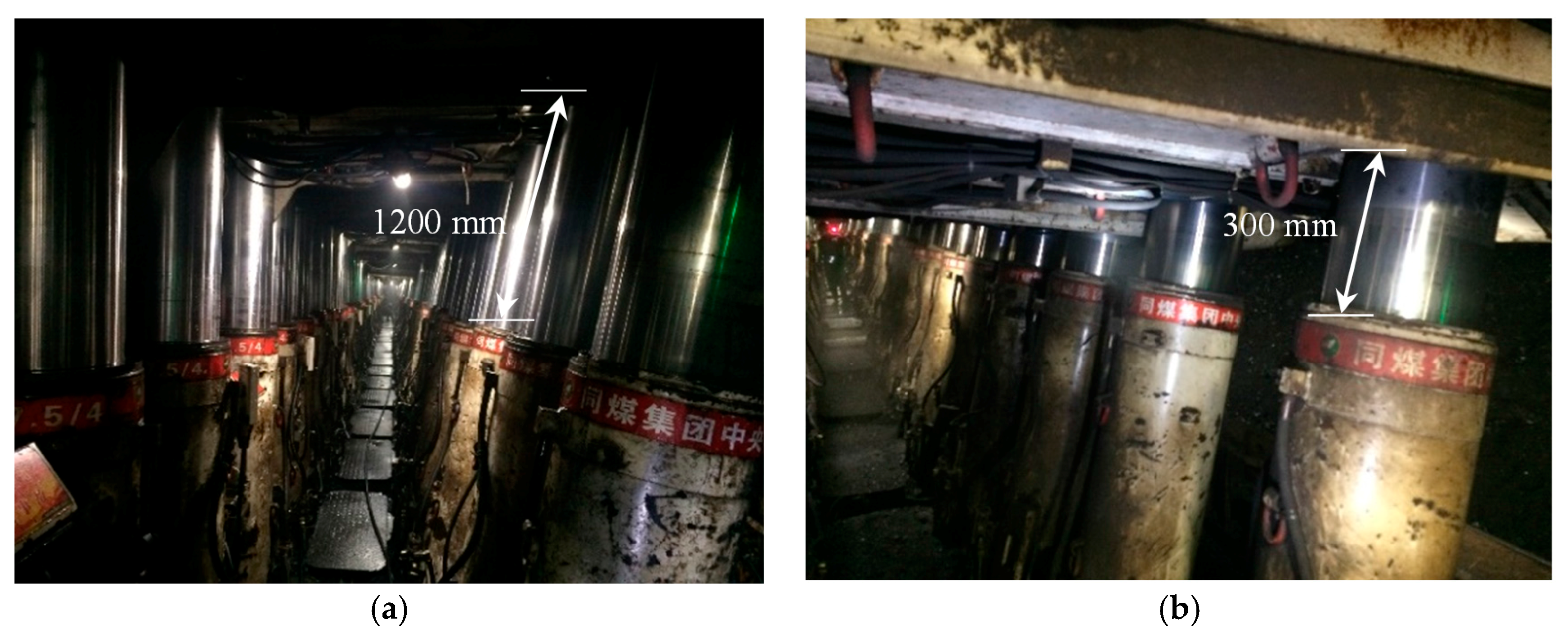
A chock support failure also occurred in LTCC-8202 of the Tongxin coal mine. The chock support (ZF/15000/27.5/42) was the same as that used in LTCC-west8101. When the working face advanced/mined to 754 m, the roof weighting occurred. Before the roof weighting, the height of the chock support plunger was 1200 mm, as shown in Figure 4a. During the weighting period, the height of the chock support descended to 300 mm in less than 30 min. The plungers of vertical hydraulic cylinders descended rapidly and the shrinkage of the No. 60–71 chock supports reached up to 700–900 mm, as shown in Figure 4b.
3. Mechanism of Support Failure Accidents
In this section, the mechanism of chock support failure in longwall top-coal caving face was investigated based on filed measurement of LTCC-west8101 and LTCC-8105. Insufficient chock support capacity and the hard top-coal are assumed to be the primary reasons for the chock support failure accidents.
3.1. The Insufficient Capacity of Chock Supports
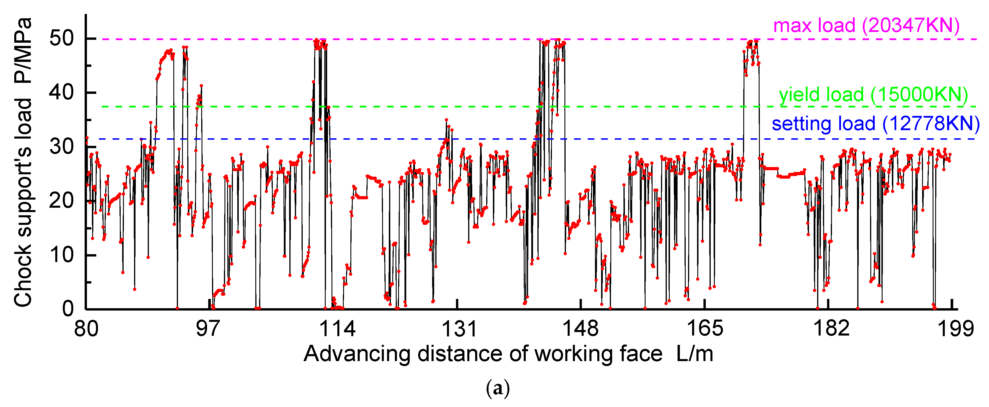
In the period of weighting, chock supports with sufficient capacity can control the roof subsidence effectively. Also, there is less shrinkage in the plungers of the vertical hydraulic cylinders along with moderate strata behavior in the working face. However, if the capacity of the supports is insufficient, there could be a significantly increasing roof subsidence which results in intense strata behavior in working faces. The load of the chock supports was monitored with the advancing/mining of LTCC-west8101. Taking the No. 65, No. 75 and No. 85 chock support in the center of LTCC-west8101 as an example, results of monitoring the load of chock supports can be seen in Figure 5.
During the period of weighting in LTCC-west8101, the No. 65 chock support’s load rose up to 50 MPa (i.e., the load on the supports was 20,347 KN). The maximum load of No. 75 and No. 85 chock supports were 18,923 KN and 19,533 KN, respectively. It can be concluded that the chock support capacity is insufficient under the mining conditions of LTCC-west8101. Therefore, the chock support was unable to support the roof effectively, resulting in the plunger of the chock supports shrinking too fast under the influence of the overlying strata. In this case, the emulsion in the hydraulic cylinder failed to discharge in time, leading to the hydraulic cylinder emulsion pressure rising, which exceeded the opening pressure of the safety valve. Consequently, this is the main reason for chock support failure and the damage to the safety valve.
Based on the above-mentioned analysis and measured results, it can be concluded that insufficient support capacity is one of most important reasons for chock support failure accidents in working faces. So, what is the ideal value of chock support capacity under the mining condition of LTCC-8101? How should it be determined? This part will be treated as a preventive measure, and answered in Section 4.1.
3.2. The Overhanging of Hard Top-Coal
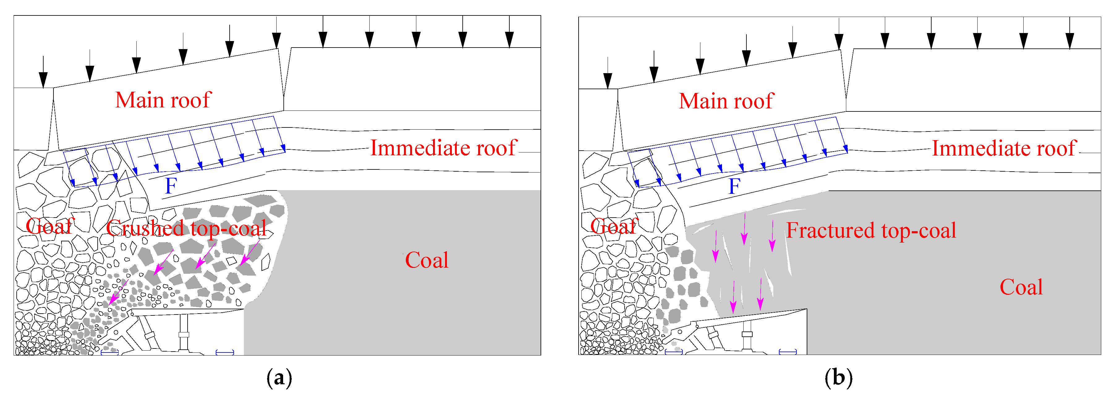
Being sandwiched between the main roofs and the supports, the top-coal is the medium through which the load of the main roof is transferred to the chock supports. Generally, if the coal strength is low and the front abutment stress is high, the top-coal can be broken easily into small pieces or blocks, resulting in successive top-coal caving. Furthermore, the crushing and caving of top-coal disperses the pressure of the main roof (“F”, as shown in Figure 6a), and as a result, the pressure from the main roof inflicted on the supports is alleviated, as shown in Figure 6a. However, if the top-coal is hard, the top-coal cannot be broken effectively and overhanging of the top-coal will occur, resulting in the pressure of the main roof (“F”, as shown in Figure 6b) transferring to the supports to a great extent, and leading to a huge, sharp shrinkage of the plungers, as shown in Figure 6b. This is the reason why the strata behavior is intense in LTCC faces with hard coal seams, while the strata behavior is moderate in LTCC faces with soft coal seams.
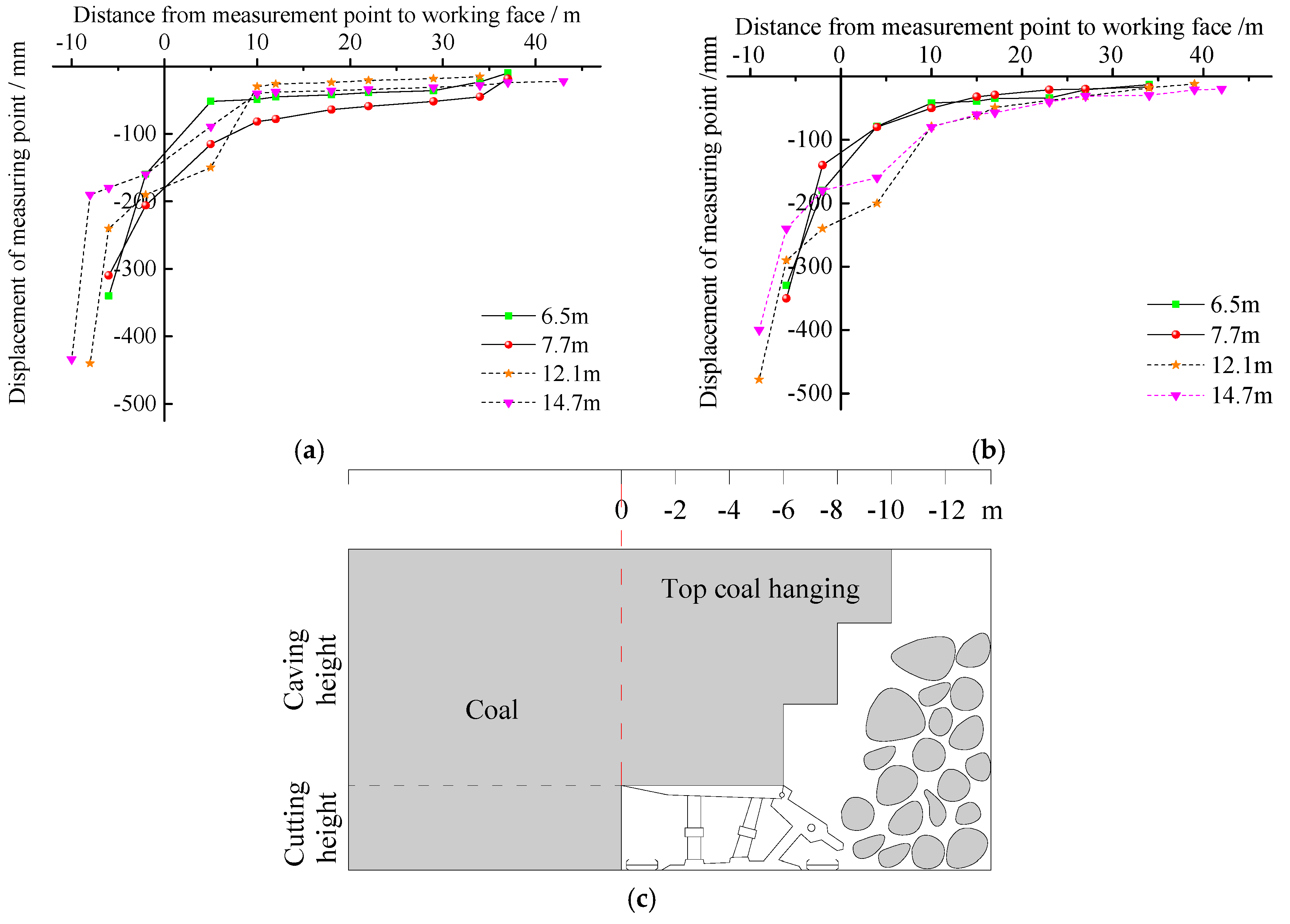
In order to judge whether there is overhanging of top-coal or not, field measurements in LTCC-8105 in the Tashan mine were conducted [23]. Two groups of drill holes were drilled in the air-return roadway against the mining direction of the working face. The angle between the hole and the roadway axis was 45°, and the spacing between the two groups was set as 15 m. Each group included two drill holes, and the angles between the axis of these two drill holes and the horizontal were 10° and 20°, respectively. Two measuring points for observing the top-coal movement were set in each drill hole. The layout of the drill holes and measuring points are shown in Figure 7.
The relationship between the displacement of the measuring point and the distance from the measuring point to the LTCC-8105 working face is shown in Figure 8. Figure 8a,b show that the low level top-coal (h = 6.5 m and h = 7.7 m, respectively) began to collapse at a distance of 7 m behind the working face, whereas the high level top-coal (h = 12.1 m and h = 14.7 m, respectively) began to collapse at a distance of 9–10 m behind the working face. The length of the chock support caving shield was 6.5 m only, thus an overhanging of top-coal was formed above the supports, as shown in Figure 8c. Based on the above-mentioned analysis and measured results, it can be concluded that the top-coal is too hard to collapse in time and the top-coal overhanging that formed behind the support is also a main reason for the intense strata behavior and chock support failure accidents in working faces.
Therefore, factors such as weakening top-coal, eliminating the overhanging of top-coal and upgrading its crushing degree should be taken into consideration. These measures are introduced in detail and comprehensively in Section 4.2.
4. Analysis and Discussion on Preventive Measures
4.1. Determination of Reasonable Support Capacity
As the main support equipment to alleviate the influence of the overlying strata loading on the working face, the chock support plays an important role in safe mining. The roof weighting on the working face is attributed to the breakage and movement of overlying strata, and it is therefore scientific and reasonable to determine the support capacity based on the overlying strata movement laws. As mentioned above, insufficient support capacity is one of the main reasons for chock support failure accidents in LTCC-west8101 of the Tongxin mine, in the Datong coalfield. Thus, it is necessary to determine the support capacity for the extra-thick coal seams of the Datong coalfield.
In the research field of underground pressure control, the key strata (KS) theory has been extensively applied and can be verified in practice. First the KS theory will be outlined briefly. Since there is a difference in the character of the layers of coal strata, each rock stratum has a different effect in rock-mass movement. These thick-and-hard strata, called KS could be seen as a control mechanism for rock mass movement; while the soft strata could be seen as the body of the load on the bottom of the thick-and-hard strata (KS). The controlling effect of the KS means that when KS break, the soft strata controlled by the KS break simultaneously, which is the basis of the KS theory proposed by Chinese academic, Qian [24]. The controlling effect of KS can be seen in Figure 9. Based on this, the determination method of the location of the KS in overlying strata is given by Qian, which can be seen in reference [24].
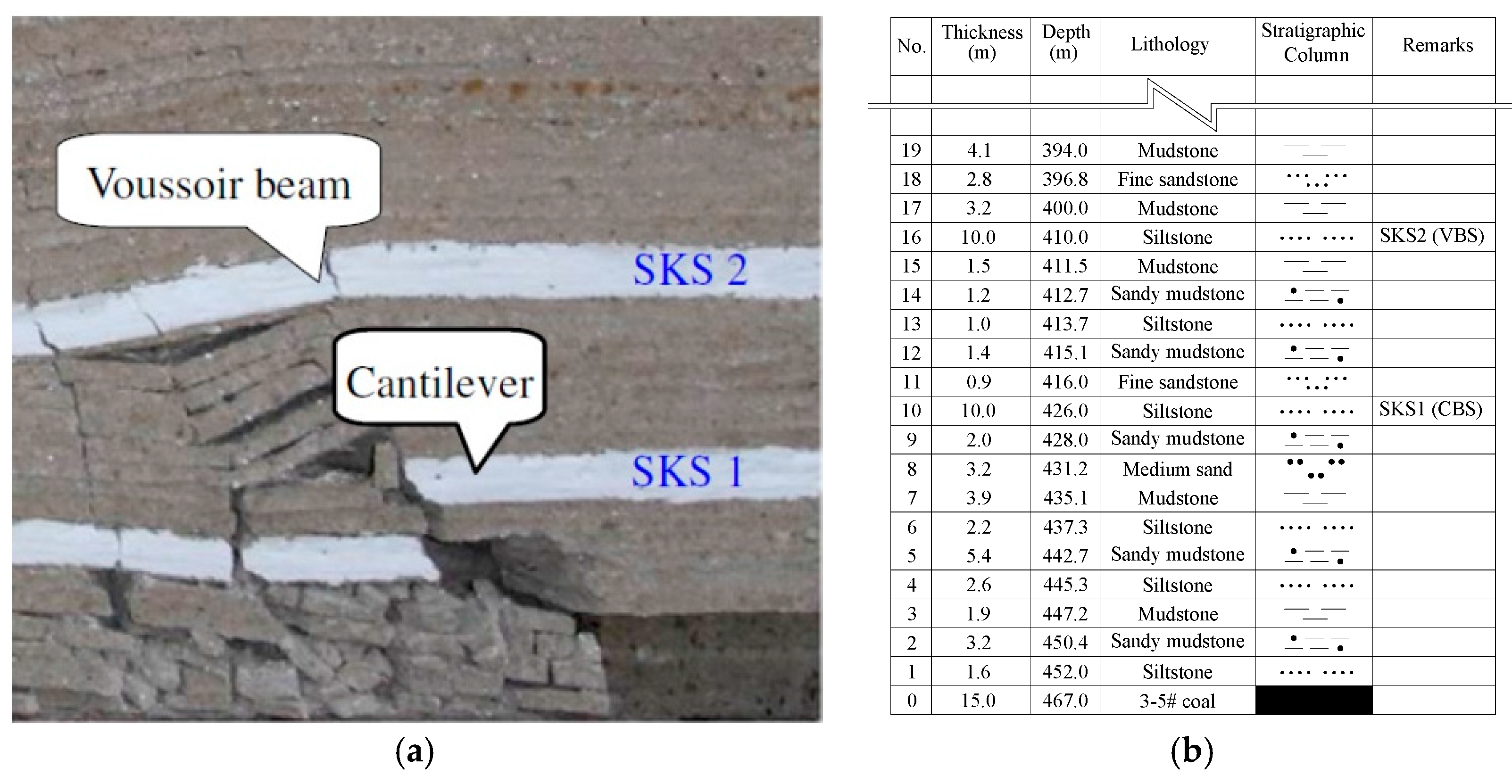
Prior to the determination of support capacity, the structural characteristics of key strata [25], which control the overlying strata movement, should be identified. Generally, if the key strata are close to the coal seam or the thickness of coal seam is large, the key strata will be located in the caving zone and form a cantilever beam structure (CBS), while if the key strata siting is far away from the coal seam or located in the fractured zone, it will be hinged together (i.e., the broken blocks of key strata can be hinged with each other) to form a voussoir beam structure (VBS) [24], as shown in Figure 10a. According to the observed results of the height of the caving zone in the longwall top-coal caving face of the extra-thick coal seam in the Datong coalfield [2] and the determination method of the structure of the key strata [24], it can be concluded that the sub-key stratum (SKS) 1 of LTCC-west8101 forms the CBS, whereas the SKS 2 (main roof) forms the VBS, as shown in Figure 10b.
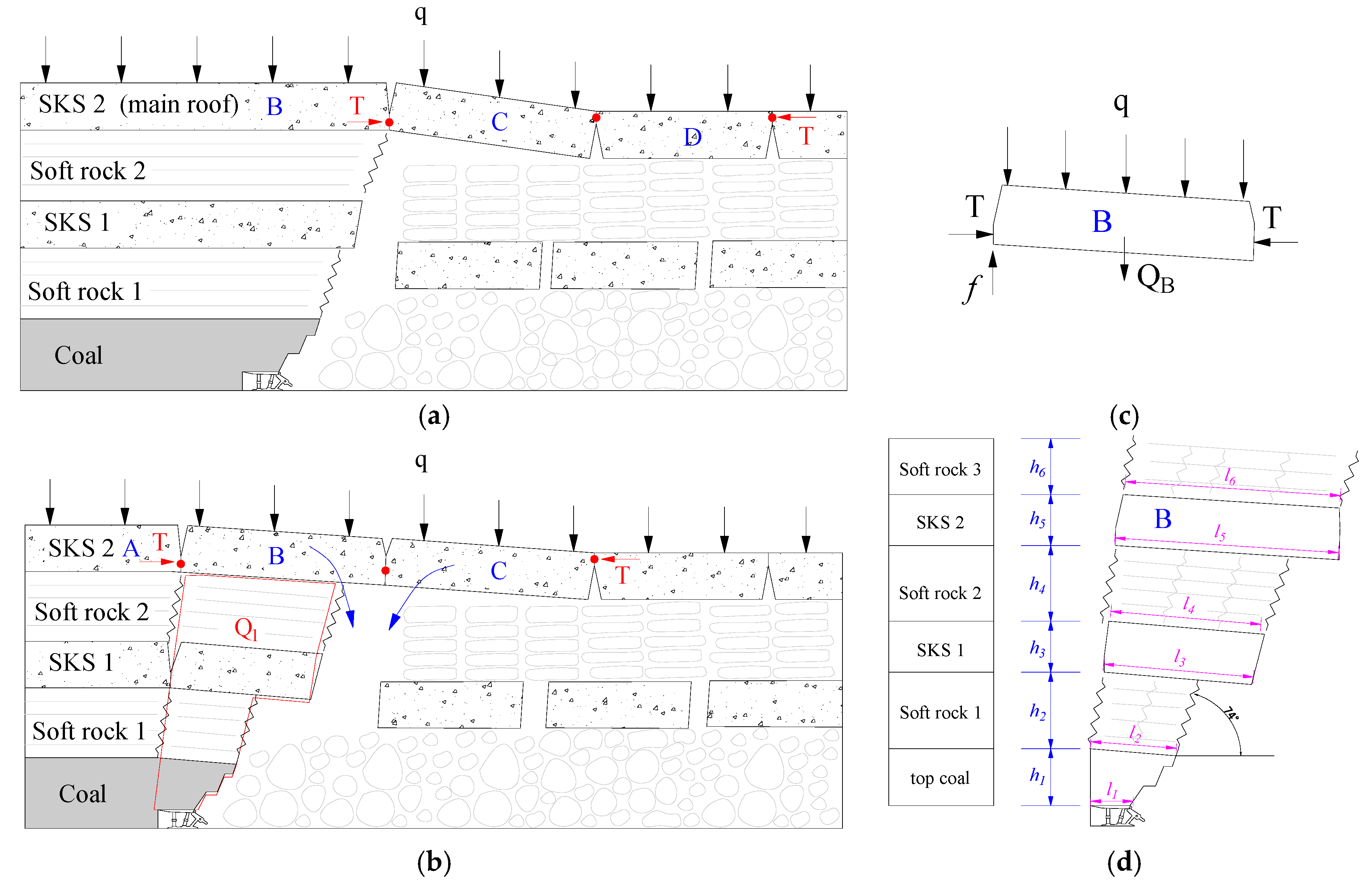
The VBS commonly consists of two broken blocks (Block C and Block D) and three hinged joints, as shown in Figure 11a. As the face advances, the SKS 1 and SKS 2 will break periodically. Prior to the breakage of SKS 2, the SKS 2 VBS is stable, as shown in Figure 11a. When the SKS 2 breaks again, the broken block B and C will rotate. Meanwhile, the loading of the SKS 2 is suddenly transferred to the support. The sudden loading of the main roof above the support is known as dynamic loading [26]. With the rotation of block B and Block C, a horizontal extrusion force T was produced at the three articulated points, which can be calculated by Equation (1). The mechanical model of this process is shown in Figure 11b.
where T is the horizontal extrusion force; q is the uniformly distributed load of overburden strata above block B; H is the thickness of block B; LB is the length of block B.
At this point, according to Figure 11b,c the acceptable support capacity can be calculated by Equation (2).
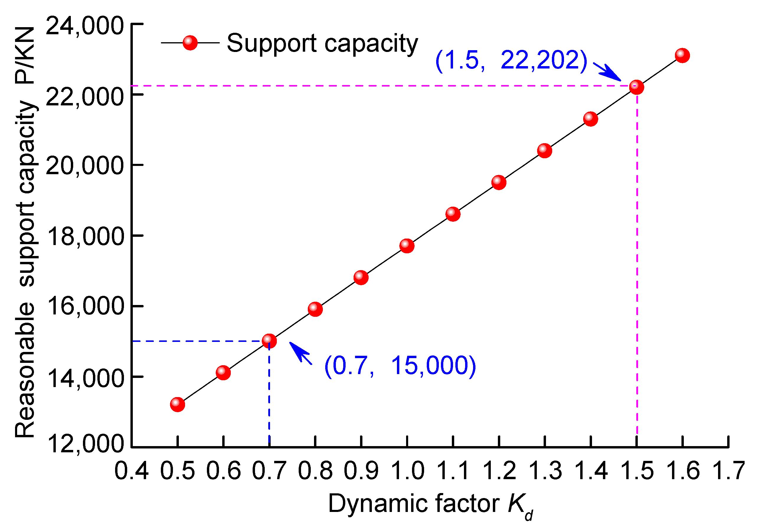
where P is the reasonable support capacity of chock supports, KN; Kd is the dynamic factor; Q1 is the gravitational loading of strata marked by the red line in Figure 11b, KN; f is the frictional force between the broken rock block B and the unbroken block A, [5]; ϕ is the angle of internal friction of broken blocks, commonly estimated to be between 30° and 40°; QB is the gravitational loading of the broken block B, KN; qLB is the loading of overburden strata above block B, KN. Generally, in longwall top-coal caving faces with soft top-coal, the value of Kd may is estimated between 1.2 and 1.3 and while in the longwall top-coal caving faces with hard top-coal, the value of the dynamic loading coefficient may be estimated to be in a higher range between 1.5 and 1.6 [27].
According to Figure 11d, the Equation (2) can be written in the following form, thus the ideal support capacity of the supports in LTCC-west8101 may be determined by Equation (3):
Taking LTCC-west8101 as an example, the relevant parameters can be determined, as shown in Table 2. From Table 2, it can be concluded that the load from the top-coal and soft rock 1 on supports was 7251 KN, while the setting load of supports was 12,778 KN, indicating that supports are able to provide favorable support. When the SKS 1 broke, the load on the supports was up to 15,251 KN and the safety valve opened, with the supporting load constantly at 15,000 KN due to the slow shrinkage speed of the plunger, which revealing the moderate strata behaviors. When the SKS 2 broke, the load on the supports was up to 20,000 KN and even 22,000 KN, which was in accordance with the measured data of 19,000 KN to 20,000 KN. Thus, under the mining conditions of the hard top-coal in the Datong coalfield, the breakage and movement of SKS 2 mainly caused the load of the overlying strata on the supports to exceed the capacity of the supports.
It is known that the reasonable support capacity, P would increase with the rise of the dynamic factor Kd. The reasonable support capacity is 22,202 KN, as shown in Figure 12 under the mining geological conditions of LTCC-west8101 with a hard top-coal. Obviously, under the existing manufacturing levels for hydraulic supports, it is infeasible to avoid chock support failure accidents just by increasing the support capacity. Technical measures of weakening the hard top-coal and upgrading its crushing degree and cavability should also be taken into consideration in order to avoid the chock support failure accidents.
4.2. Hydraulic Fracturing for Hard Top-Coal
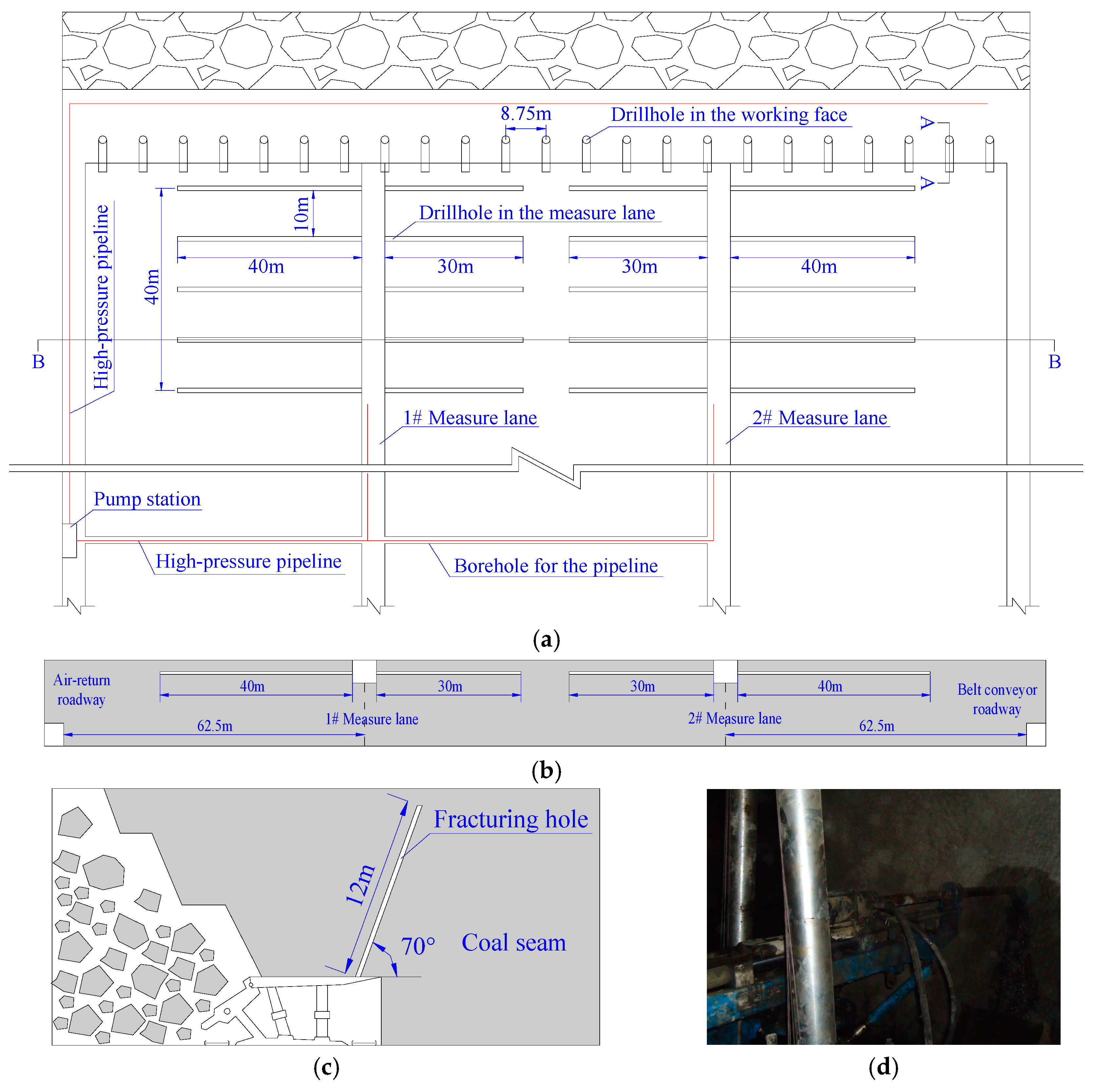
Various measures are taken to weaken the top-coal and improve its cavability to avoid chock support failure accidents. Hydraulic fracturing is the most effective way to weaken the top-coal in situations in which explosives are not feasible due to high gas levels, such as in LTCC-west8101. Referring to the layout method of the fracturing drill holes on hard coal seams [20,27], hydraulic fracturing is conducted in LTCC-west8101. In the mining process, the top-coal is fractured in advance. The drill holes are drilled on the working face and the two measure lanes which are excavated along the roof are both 62.5 m from the air-return-roadway and belt conveyor roadway respectively, as shown in Figure 13a,b. The oblique drill holes are drilled between the supports at a distance of 8.75 m (every five supports) and the drill hole is inclined to the coal wall in front of the working face at an angle of 70°, as shown in Figure 13c. The depth of the drill hole is 14 m (1 m higher than the top-coal). The pump pressure is 45 MPa, and the pump is stopped after 20 min of hydraulic fracturing or when the orifice water pressure is below 20 MPa. The horizontal drill holes, whose depths along the perpendicular to the mining direction vary at about 30 m or 40 m, are drilled at an interval of 10 m along the mining direction in the measure lane. The horizontal drill holes are drilled at least 40 m ahead of the working face in the measure lane, meaning five horizontal drill holes drilled in each column, as shown in Figure 13a. The pump pressure is 45 MPa, and the pump is stopped after 1 h of hydraulic fracturing or when the orifice water pressure is below 20 MPa. The relative parameters can be determined according to the research findings [20,27].
4.3. Optimization of Caving Process
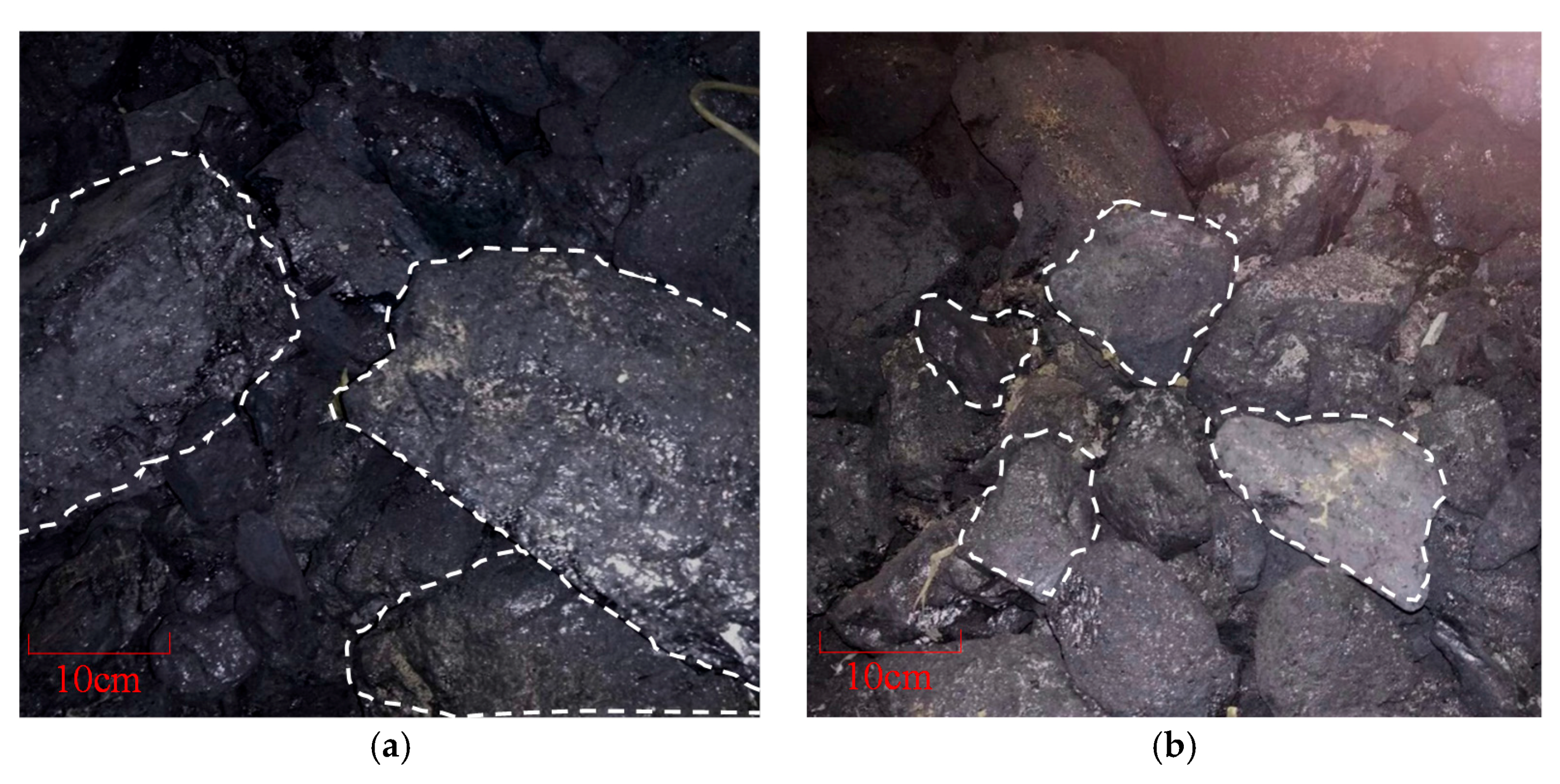
By hydraulic fracturing, the integrity of hard top-coal is destroyed and lots of fractures are generated which improve the cavability of the hard top-coal, and more importantly, the overhanging of hard top-coal is avoided. Based on that, in order to further upgrade the crushing effect of top-coal and reduce the block size of broken top-coal, the chock supports are raised up and down repeatedly by manual operation before moving the chock support forward, which can help the top-coal to be crushed into smaller blocks or pieces, as shown in Figure 6a above. In this case, the pressure from the main roof inflicted on the chock supports is alleviated and the strata behavior in the working face is moderate [16].
Previously, mining pursued the rapid advancement of the working face, and the top-coal caving process was executed before the top-coal was crushed sufficiently. Therefore, on the one hand, the top-coal had difficulty falling and failed to be recovered, resulting in waste of coal resources; on the other hand, this part of the top-coal that failed to be crushed fully, served as a transfer medium of the pressure from the main roof to the chock supports, as shown in Figure 6b above, resulting in intense strata behaviors.
Hence, in subsequent mining production at LTCC-west8101, it is recommended that the mine workers should raise the chock supports up and down repeatedly as much as possible as this helps to reduce the size of the blocks or pieces of top-coal, as shown in Figure 14.
5. Engineering Implementation Effect
The prevention of chock support failure accidents in fully mechanized faces of extremely thick coal seams in the Datong coalfield had gone through three main stages. At the early stage, around 2008–2010, when the supports with a capacity of 10,000 KN and 13,000 KN were used in the mining face, the majority of fully mechanized mining faces experienced chock support failure accidents during the recovery process, and almost all the supports failed with the plunger of vertical hydraulic cylinders descending rapidly, reaching up to 1000 mm, as well as the hydraulic cylinder of the support being crushed frequently. Limited by the temporal level of understanding, chock support failure accidents were thought to be caused by insufficient support capacity. Therefore, from 2010 to 2015, support capacity was increased to 15,000 KN but no measures for weakening top-coal were adopted. However, chock support failure accidents still happened frequently with the plunger of vertical hydraulic cylinders descending rapidly, reaching up to more than 800 mm, and the support load inflicted was 19,000–22,000 KN. After 2015, with the improvement in understanding of the top-coal in fully mechanized faces, the relationship between top-coal and chock support failure accidents was gradually discovered. It was unrealistic to simply increase chock support capacity rather than adopt measures for weakening top-coal to avoid chock support failure accidents. Based on this, other approaches, according to theoretical analysis, were proposed, including hydraulic fracturing for hard top-coal and optimization of the caving process (chock supports raised up and down repeatedly by manual operation before moving forward), to lower the integrity and strength of top-coal and upgrade its crushing effect to weaken the support load effectively during the weighting period, which reduces the likelihood of chock support accidents occurring.
It should be noted that during the early stage of prevention of chock support failure accidents, the method of hydraulic fracturing had been applied but for fracturing the hard roof above the hard coal to weaken strata behaviors. In this case, the stress of pump stations should up to 60 MPa, and therefore the reliable operation of this kind of equipment for improving fracturing stress became the greatest challenge. For one thing, the low stress could not effectively fracture the hard rock mass of the roof. For another, there is a high demand for the pressure-resistance requirement for the pressure line of 60 MPa, which presents potential safety hazard, for example, the pipeline bursting. With a change in practice, that is, hydraulic fracturing for hard top-coal rather than the roof, a pump stress of 20 MPa was indicated to meet the demand and improve the effect. The decrease in fracturing stress not only ensures the safe operation of equipment but also reduces the fracturing period, which means the fracturing efficiency is improved.
Having applied the above-mentioned measures, the good experimental effect was obtained. The top-coal can be fully smashed by hydraulic fracturing and the chock supports raised up and down repeatedly. According to the test results, the load on the chock supports decreased significantly during the period of weighting. The maximum load of chock support decreased from 19,000~20,000 KN to 14,400~16,000 KN (with a reduction ratio of 11–28% or so). Additionally, the shrinkage of the plunger of the chock support also decreased (the maximum shrinkage was less than 300 mm) during roof weighting. The number of chock support failure accidents has been greatly decreased.
6. Conclusions
Chock support failure accidents in fully mechanized faces of extremely thick coal seams in the Datong coalfield had seriously restricted safe and highly efficient mining. For this reason, the occurrence mechanism of chock support failure was studied in this paper. The research indicated that hard top-coal and insufficient chock support capacity were primary reasons for chock support failure accidents. Based on this, a new method to determine support capacity was proposed, which fully took the impact of the top-coal strength into consideration, and some measures, including hydraulic fracturing for hard top-coal and optimization of the caving process (chock supports raised up and down repeatedly by manual operation before moving forward), were presented to prevent chock support accidents occurring.
- (1)
- The intense strata behavior is a typical problem in hard coal seams with the LTCC method, and the harder the top-coal is, the stronger the strata behavior appears, even leading to chock support failure accidents, which has been confirmed by mining practices in the Datong coal field in recent years. Therefore, top-coal can no longer be regarded as a soft cushion for alleviating the strata behavior and the chock support load. This is a good addition to a more comprehensive understanding of the relationship between the top-coal and the strata behavior in the longwall top-coal caving face.
- (2)
- The results of this study show that the insufficient capacity of supports and the overhanging of hard top-coal were the primary reasons for the chock support failure accidents in the LTCC face in the Datong coalfield. A reasonable support capacity was determined based on a mechanical model. Meanwhile, the measures of weakening top-coal by hydraulic fracturing and upgrading the crushing degree of top-coal by raising supports up and down repeatedly through manual operation were proposed for relieving strata behavior and avoiding chock support failure accidents.
- (3)
- Through field measurement, the proposed measures proved to be effective. After these measures had been applied, the maximum chock support load decreased from 18,000~20,000 KN to 14,400~16,000 KN and the shrinkage of the plunger of vertical hydraulic cylinders is less than 300 mm during the roof weighting. Most importantly, chock support failure accidents were largely eliminated in the LTCC face in subsequent production of the extra-thick hard coal seams in the Datong coalfield.
LTCC is the main mining method for thick and extremely thick coal seams; thus it has huge application potential considering the growing demand for coal resources. The effective control of mining pressure is a fundamental basis for safe and high-efficiency mining. However, research has been limited to the study of overlying strata movement in understanding the strata behaviors of fully mechanized faces. It seems unwise to neglect the top-coal that is the main medium through which the load of overlying strata is transferred to the chock supports. Therefore, when considering the problems or puzzles of mine pressure in fully mechanized faces, the study of top-coal should be taken into account. In addition, for coal mine workers, when facing strong strata behaviors in fully mechanized faces, like chock support failure accidents, some measures, such as hydraulic fracturing for hard top-coal and optimization of caving processes (chock supports raised up and down repeatedly by manual operation before moving forward), can be harnessed to destroy the integrity of top-coal, to lower the strength of top-coal and upgrade its crushing effect, in order to weaken the support load effectively during the weighting period, which means less likelihood of chock supports accidents occurring.
Acknowledgments
This work is supported by the State Key Research Development Program of China (2016YFC0501109) and National Nature Science Foundation of China (51604259). The authors gratefully acknowledge the financial support from the organizations mentioned above.
Author Contributions
For this paper, Jialin Xu put forward study ideas; Zhu Li designed the article structure and wrote the paper; Shengchao Yu revised the whole the English writing style and discussed the design flow with Zhu Li; Jinfeng Ju conducted the theoretical simulation and analyzed the data; Jingmin Xu collected and analyzed the data from mine site.
Conflicts of Interest
The authors declare no conflict of interest.
References
- Xie, H.P.; Zhou, H.W. Application of fractal theory to top-coal caving. Chaos Solitons Fractals 2008, 36, 797–807. [Google Scholar] [CrossRef]
- Yu, B.; Zhao, J.; Kuang, T.J.; Meng, X.B. In situ investigations into overburden failures of a super-thick coal seam for longwall top coal caving. Int. J. Rock Mech. Min. Sci. 2015, 78, 155–162. [Google Scholar] [CrossRef]
- Yu, B. Study on Strong Pressure Behavior Mechanism and Roof Control of Fully Mechanized Top Coal Caving in Extra Thickness Seam in Datong Coal Mine. Doctoral Dissertation, China University of Mining and Technology, Xuzhou, China, 2014. (In Chinese). [Google Scholar]
- Yasitli, N.E.; Unver, B. 3D numerical modeling of longwall mining with top-coal caving. Int. J. Rock Mech. Min. Sci. 2005, 42, 219–235. [Google Scholar] [CrossRef]
- Qian, M.G.; Shi, P.W.; Xu, J.L. Ground Pressure and Strata Control, 2rd ed.; China University of Mining and Technology Press: Xuzhou, China, 2010; pp. 271–275. [Google Scholar]
- Ju, J.F.; Xu, J.L. Longwall chock sudden closure incident below coal pillar of adjacent upper mined coal seam under shallow cover in the Shendong coal field. Int. J. Rock Mech. Min. Sci. 2015, 77, 192–201. [Google Scholar] [CrossRef]
- Xu, J.L.; Zhu, W.B.; Ju, J.F. Supports crushing types in the longwall mining of shallow seams. J. China Coal Soc. 2014, 39, 1625–1634. (In Chinese) [Google Scholar]
- Xie, Y.S.; Zhao, Y.S. Numerical simulation of the top coal caving process using the discrete element method. Int. J. Rock Mech. Min. Sci. 2009, 46, 983–991. [Google Scholar] [CrossRef]
- Yang, S.L.; Wang, J.C.; Chen, Y.; Song, Z.Y. Effect of upward angle on the drawing mechanism in longwall top-coal caving mining. Int. J. Rock Mech. Min. Sci. 2016, 85, 92–101. [Google Scholar] [CrossRef]
- Vakili, A.; Hebblewhite, B.K. A new cavability assessment criterion for longwall top coal caving. Int. J. Rock Mech. Min. Sci. 2010, 47, 1317–1329. [Google Scholar] [CrossRef]
- Wang, J.C.; Zhang, J.W.; Li, Z.L. A new research system for caving mechanism analysis and its application to sublevel top-coal caving mining. Int. J. Rock Mech. Min. Sci. 2016, 88, 273–285. [Google Scholar] [CrossRef]
- Alehossein, H.; Poulsen, B.A. Stress analysis of longwall top coal caving. Int. J. Rock Mech. Min. Sci. 2010, 47, 30–41. [Google Scholar] [CrossRef]
- Xie, J.; Gao, M.Z.; Zhang, R.; Li, S.W.; Tan, Q.; Qiu, Z.Q. Lessons learnt from measurements of vertical pressure at a top coal mining face at Datong Tashan mines, China. Rock Mech. Eng. 2016, 49, 2977–2983. [Google Scholar] [CrossRef]
- Unver, B.; Yasitli, N.E. Modelling of strata movement with a special reference to caving. Int. J. Rock Mech. Min. Sci. 2006, 66, 227–252. [Google Scholar]
- Zhang, N.B.; Liu, C.Y. Arch structure effect of the coal gangue flow of the fully mechanized caving in special thick coal seam and its impact on the loss of top coal. Int. J. Min. Sci. Technol. 2016, 26, 593–599. [Google Scholar] [CrossRef]
- Huang, P.; Ju, F.; Jessu, K.V.; Xiao, M.; Guo, S. Optimization and Practice of Support Working Resistance in Fully-Mechanized Top Coal Caving in Shallow Thick Seam. Energies 2017, 10, 1046. [Google Scholar] [CrossRef]
- Zhao, Y.S.; Xie, Y.S.; Guo, J.G.; Huo, L.J. Technical principle of top coal caving with vibration and its practice. Chin. J. Mech. Eng. 2008, 27, 187–192. (In Chinese) [Google Scholar]
- Yu, B.; Xia, H.C.; Meng, X.B. Top coal arching mechanism and arch removal strategies in fully mechanized top coal caving mining of ultra-thick coal seam. J. China Coal Soc. 2016, 41, 1617–1623. (In Chinese) [Google Scholar]
- Gao, F.Q.; Stead, D.; Coggan, J. Evaluation of coal longwall caving characteristics using an innovative UDEC trigon approach. Comput. Geotech. 2014, 55, 448–460. [Google Scholar] [CrossRef] [Green Version]
- Huang, B.X.; Wang, Y.Z.; Cao, S.G. Cavability control by hydraulic fracturing for top coal caving in hard thick coal seams. Int. J. Rock Mech. Min. Sci. 2015, 74, 45–57. [Google Scholar] [CrossRef]
- Zhang, H.W.; Zhu, Z.J.; Huo, L.J.; Chen, Y.; Huo, B.J. Overburden failure height of superhigh seam by fully mechanized caving method. J. China Coal Soc. 2014, 39, 816–821. (In Chinese) [Google Scholar]
- Huo, B.J.; Yu, B.; Zhang, H.W.; Lu, Y.B. Study on formation mechanism of arch shell large structure of overburden in coal mining face with multi layer hard roof. Coal Sci. Technol. 2016, 44, 18–23. (In Chinese) [Google Scholar]
- Wang, J.H.; Yu, B.; Kang, H.P.; Wang, G.F.; Mao, D.B.; Liang, Y.T.; Jiang, P.F. Key technologies and equipment for a fully mechanized top-coal caving operation with a large mining height at ultra-thick coal seams. Int. J. Coal Sci. Technol. 2015, 2, 97–161. [Google Scholar] [CrossRef]
- Ju, J.F.; Xu, J.L. Structural characteristics of key strata and strata behaviour of a fully mechanized longwall face with 7.0 m height chocks. Int. J. Rock Mech. Min. Sci. 2013, 58, 46–54. [Google Scholar]
- Ju, J.F.; Xu, J.L. Surface stepped subsidence related to top-coal caving longwall mining of extremely thick coal seam under shallow cover. Int. J. Rock Mech. Min. Sci. 2015, 78, 27–35. [Google Scholar] [CrossRef]
- Wang, J.C.; Yang, S.L.; Li, Y.; Wang, Z.H. A dynamic method to determine the supports capacity in longwall coal mining. Int. J. Min. Reclam. Environ. 2015, 29, 277–288. [Google Scholar] [CrossRef]
- Lu, Y.Y.; Cheng, Y.G.; Ge, Z.L.; Cheng, L.; Zuo, S.J.; Zhong, J.Y. Determination of Fracture Initiation Locations during Cross-Measure Drilling for Hydraulic Fracturing of Coal Seams. Energies 2016, 9, 358. [Google Scholar] [CrossRef]
Figure 1.
A conceptual model of top-coal fracturing and drawing in longwall top-coal caving (LTCC).
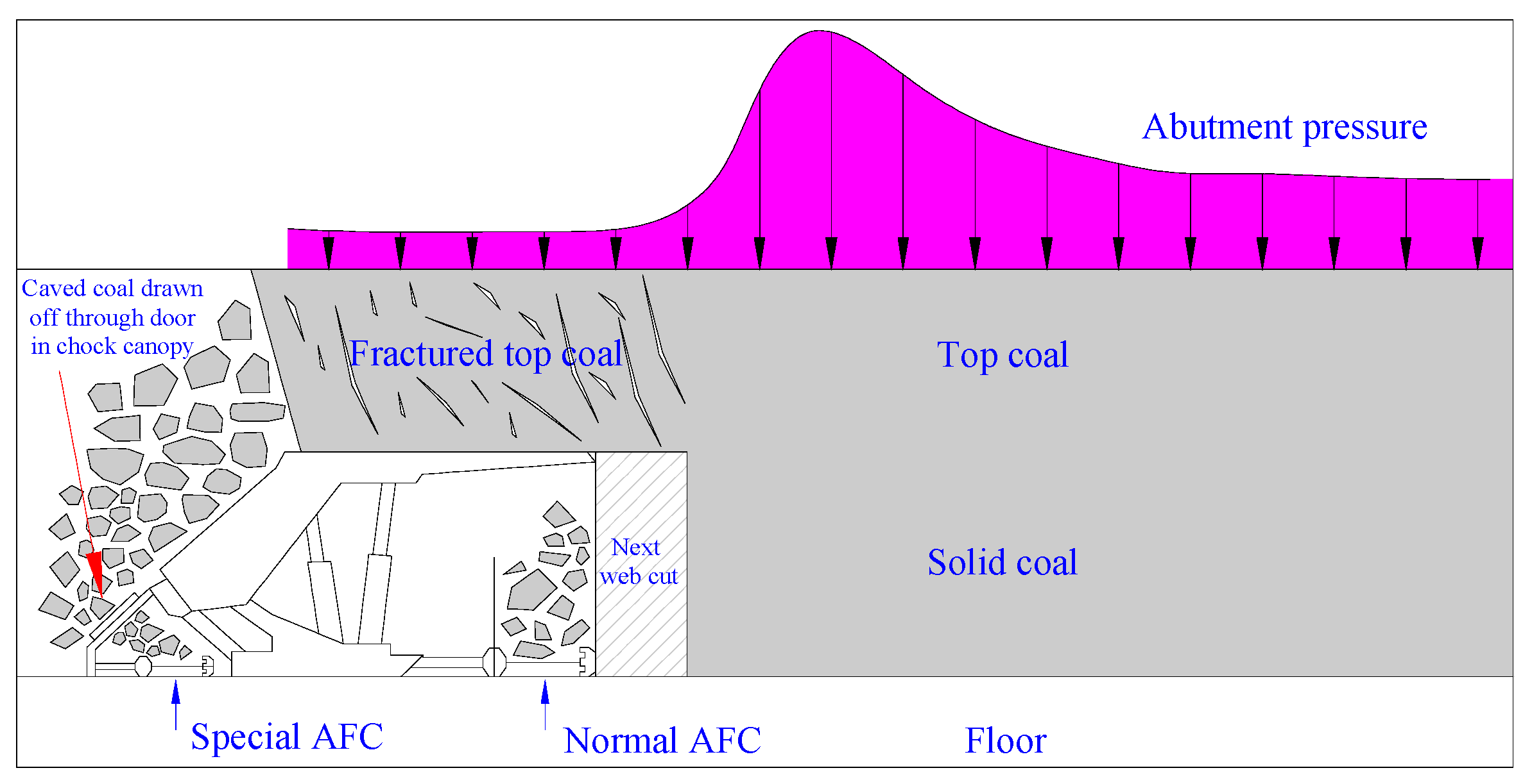
Figure 2.
Distribution diagram of chock support failure accidents: (a) Tongxin mine; (b) Tashan mine.
Figure 2.
Distribution diagram of chock support failure accidents: (a) Tongxin mine; (b) Tashan mine.
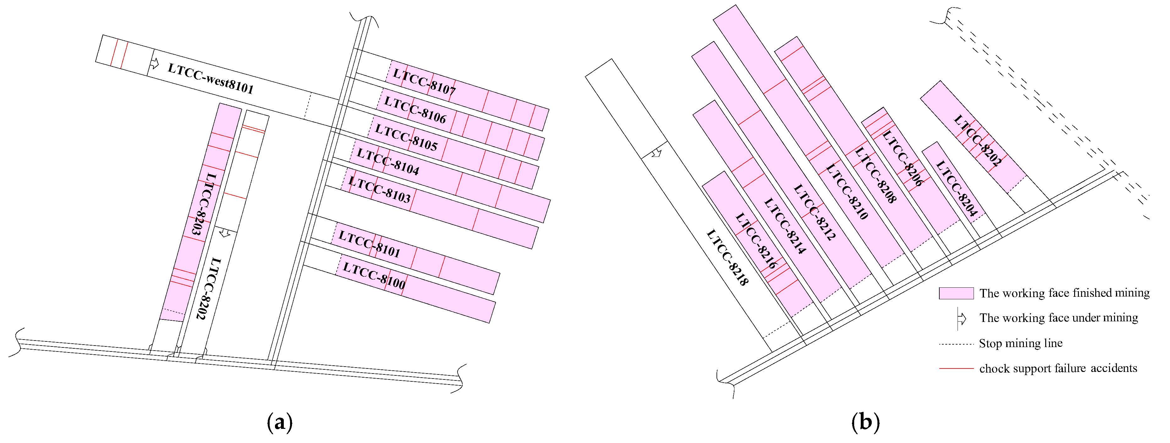
Figure 3.
Photographic views of the accidents in LTCC-west8101: (a) Plunger descended; (b) Chock support crushed.
Figure 3.
Photographic views of the accidents in LTCC-west8101: (a) Plunger descended; (b) Chock support crushed.
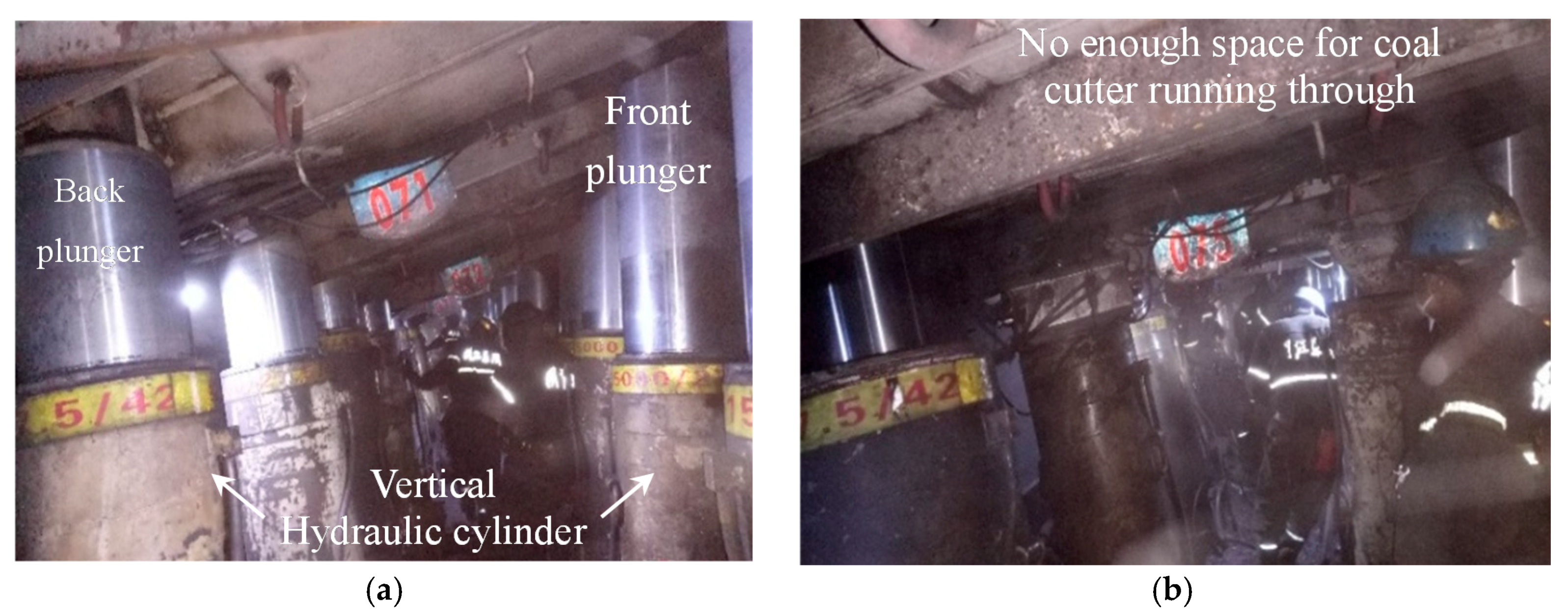
Figure 4.
Photographic views of the accidents in LTCC-8202: (a) Before roof weighting; (b) After roof weighting.
Figure 4.
Photographic views of the accidents in LTCC-8202: (a) Before roof weighting; (b) After roof weighting.

Figure 5.
The curves of the load of the chock supports: (a) No. 65# support; (b) No. 75# support; (c) No. 85# support.
Figure 5.
The curves of the load of the chock supports: (a) No. 65# support; (b) No. 75# support; (c) No. 85# support.

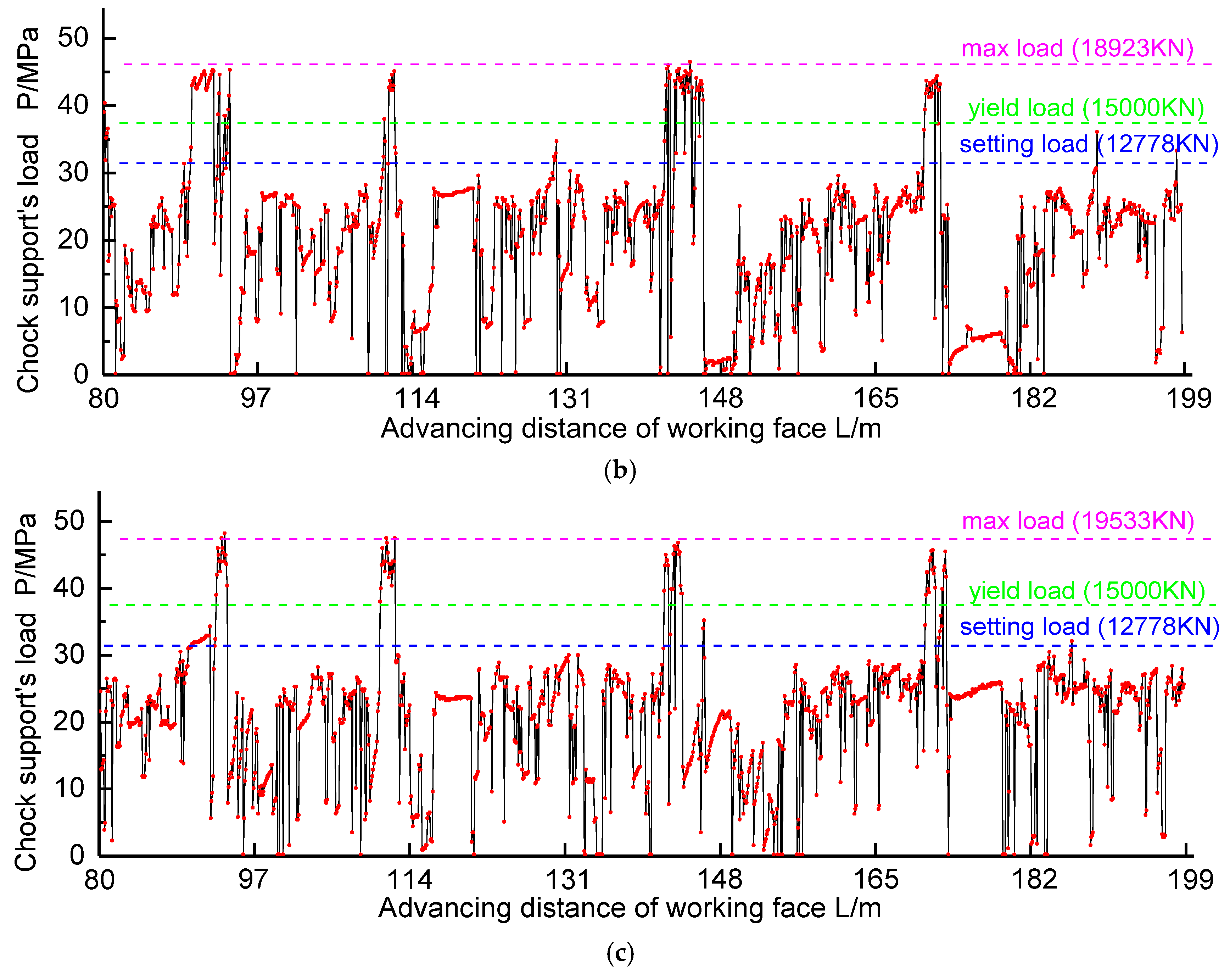
Figure 6.
Influence of top-coal strength on the chock support load in LTCC: (a) Soft top-coal; (b) Hard top-coal.
Figure 6.
Influence of top-coal strength on the chock support load in LTCC: (a) Soft top-coal; (b) Hard top-coal.

Figure 7.
The layout of drill holes and measuring points: (a) The layout of drill holes group No. 1 and group No. 2; (b) Cross-sectional view from A–A.
Figure 7.
The layout of drill holes and measuring points: (a) The layout of drill holes group No. 1 and group No. 2; (b) Cross-sectional view from A–A.
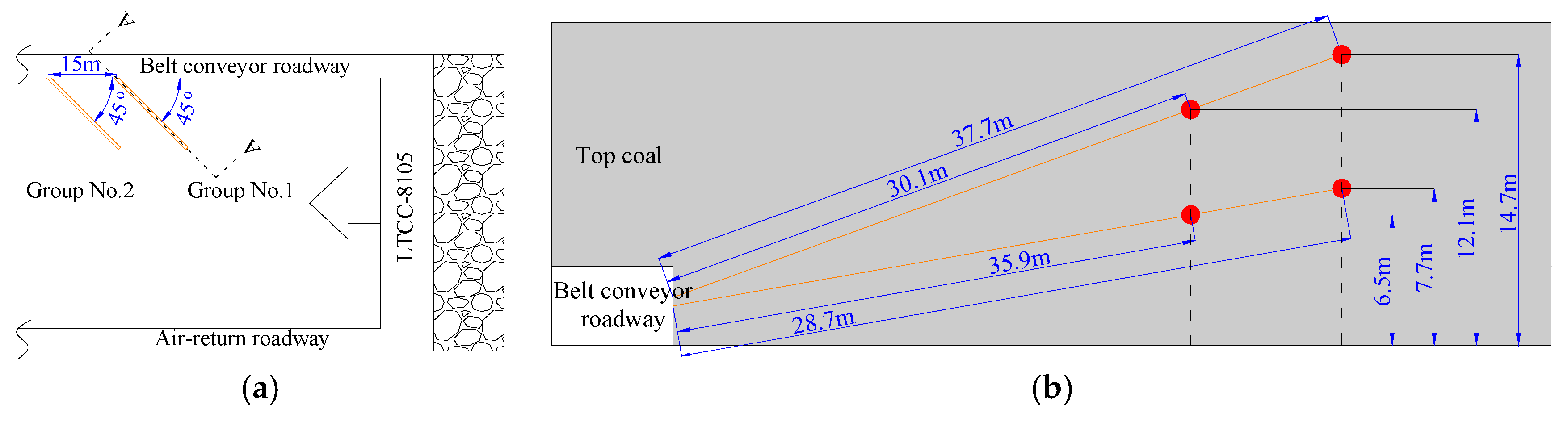
Figure 8.
The movement patterns and the overhanging of top-coal in LTCC-8105: (a) The displacement of measuring points in Group No. 1; (b) The displacement of measuring points in Group No. 2; (c) Top-coal overhanging.
Figure 8.
The movement patterns and the overhanging of top-coal in LTCC-8105: (a) The displacement of measuring points in Group No. 1; (b) The displacement of measuring points in Group No. 2; (c) Top-coal overhanging.

Figure 9.
Controlling effect of KS. (a) Controlling effect of SKS 1; (b) Controlling effect of SKS 2; (c) Controlling effect of SKS 3.
Figure 9.
Controlling effect of KS. (a) Controlling effect of SKS 1; (b) Controlling effect of SKS 2; (c) Controlling effect of SKS 3.
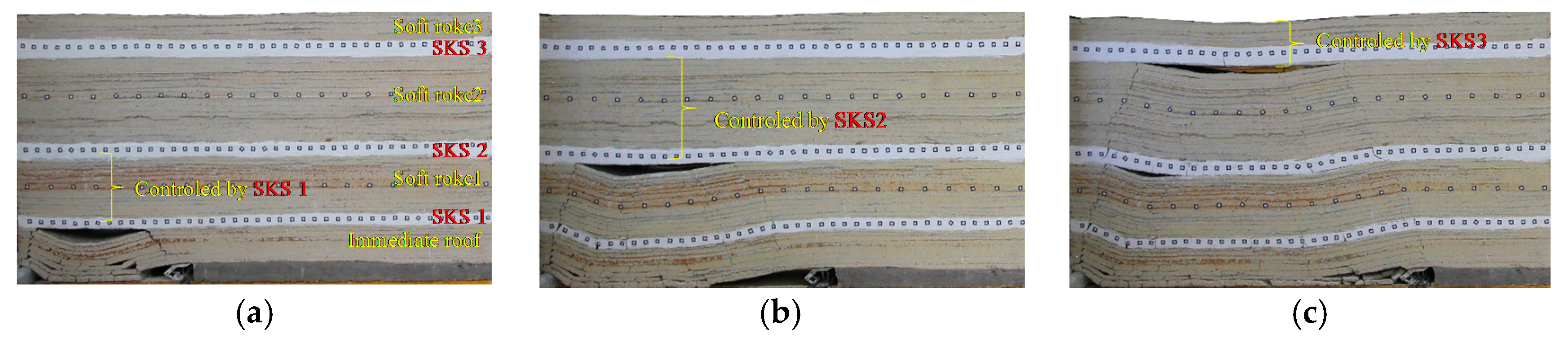
Figure 10.
Diagram of the structural characteristics of key strata: (a) The structural features of VBS and CBS [24]; (b) Borehole column and the KS location of LTCC-west8101.
Figure 10.
Diagram of the structural characteristics of key strata: (a) The structural features of VBS and CBS [24]; (b) Borehole column and the KS location of LTCC-west8101.

Figure 11.
The mechanical model governing the chock support load calculation: (a) Structural feature before the breakage of SKS 2; (b) The rotating movement of Block B and Block C after the breakage of SKS 2; (c) The stress distribution of Block B; (d) Calculation of the chock support load based on the structural features after the breakage of SKS 2.

Figure 12.
The reasonable support capacity under different dynamic factors of the main roof.

Figure 13.
Drill holes layout and site operation in LTCC-west8101: (a) Plan view; (b) Cross-sectional view from B-B; (c) Cross-sectional view from A-A; (d) Drilling construction of the horizontal drill hole.
Figure 13.
Drill holes layout and site operation in LTCC-west8101: (a) Plan view; (b) Cross-sectional view from B-B; (c) Cross-sectional view from A-A; (d) Drilling construction of the horizontal drill hole.

Figure 14.
The crushing effect variation of top-coal before and after the measure being applied: (a) Before measuring; (b) After measuring.
Figure 14.
The crushing effect variation of top-coal before and after the measure being applied: (a) Before measuring; (b) After measuring.


Table 1.
Case statistics of chock support failure accidents in the Tongxin and Tashan mines.
| Coal Mine | Working Face | Face Width/Mining Height/(m) | Support Resistance (KN) | Accidents Position/Advancing Distance (m) | Support Shrinkage (mm) |
|---|---|---|---|---|---|
| Tongxin | LTCC-8101 | 205/13.5 | 15,000 | 502(45#~66#), 761(55#~80#), 1088(65#~82#), 1435(40#~66#) | 1000–1200 |
| LTCC-8100 | 205/13.5 | 15,000 | 808(30#~50#), 964(45#~58#) | 900–1100 | |
| LTCC-8106 | 212/12.8 | 15,000 | 143(65#~75#), 300(65#~78#), 482(67#~83#), 706(50#~70#), 817(39#~79#), 1208(50#~76#) | 800–1100 | |
| LTCC-8107 | 240/14.3 | 15,000 | 114(70#~85#), 295(50#~65#), 545(72#~88#), 850(45#~70#), 1049(60#~75#), 1309(50#~80#) | 800–1200 | |
| LTCC-8105 | 200/14.5 | 15,000 | 158(35#~50#), 310(47#~80#), 490(59#~79#), 844(47#~98#), 1140(67#~83#) | 800–1000 | |
| LTCC-8104 | 206/14 | 15,000 | 434(45#~65#), 796(52#~74#), 1476(38#~67#), 1567(62#~90#) | 800–1100 | |
| LTCC-8103 | 200/14 | 15,000 | 538(47#~59#), 1121(60#~70#), 1481(82#~97#), 1677(40#~60#) | 700–1100 | |
| LTCC-8203 | 203/14.5 | 15,000 | 269(47#~67#), 386(30#~45#), 561(40#~60#), 703(25#~55#), 1033(50#~75#), 1210(30#~45#), 1505(40#~60#), 1571(35#~58#), 1622(37#~65#) | 800–1200 | |
| LTCC-west8101 | 245/14 | 15,000 | 98(45#~60#), 115(60#~87#) | 800–1000 | |
| LTCC-8202 | 200/14 | 15,000 | 137(37#~54#), 156(35#~63#), 378(60#~82#), 754(56#~88#), | 700–900 | |
| Tashan | LTCC-8202 | 236/12 | 10,000 | 460(50#~60#), 539(70#~82#), 629(47#~62#), 706(82#~94#), 872(56#~67#) | 500–1000 |
| LTCC-8206 | 237/12.5 | 13,000 | 62(42#~55#), 142(24#~82#), 184(54#~70#), 551(55#~78#), 649(46#~75#), 732(43#~68#) | 600–900 | |
| LTCC-8208 | 236/13 | 13,000 | 102(61#~76#), 415(60#~80#), 450(72#~95#), 529(61#~80#), 1098(47#~72#), 1219(77#~98#) | 800–1000 | |
| LTCC-8210 | 236/12.8 | 13,000 | 780(54#~72#), 1431(37#~85#), 1485(45#~62#), 1630(52#~79#) | 600–900 | |
| LTCC-8212 | 235/13.5 | 13,000 | 713(35#~49#), 1702(63#~82#) | 700–1000 | |
| LTCC-8214 | 230/13 | 13,000 | 590(55#~75#), 763(63#~87#) | 600–900 | |
| LTCC-8216 | 236/13.8 | 15,000 | 518(40#~56#), 906(47#~69#), 967(62#~83#), 1016(34#~70#), 1133(50#~92#) | 700–1000 | |
| Cumulative number of regional support-crushing accidents | 76 | ||||
Table 2.
Values of parameters in Equation (3) under mining geological conditions of LTCC-west8101.
| Strata | Bulk Density /N × m−3 | Thickness /m | Length /m |
|---|---|---|---|
| Top-coal | = 14,000 | h1 = 11 | l1 = 6.5 |
| Soft rock 1 | = 25,000 | h2 = 25 | l2 = 10 |
| SKS 1 | = 25,000 | h3 = 10 | l3 = 20 |
| Soft rock 2 | = 25,000 | h4 = 6 | l4 = l3 = 20 |
| SKS 2 (main roof) | = 25,000 | h5 = 13 | l5 = 30 |
| Soft rock 3 | = 25,000 | h6 = 10 | l6 = l5 = 30 |
Note: l3 and l5 can be determined according to field measurement of periodic weighting interval [24].
© 2018 by the authors. Licensee MDPI, Basel, Switzerland. This article is an open access article distributed under the terms and conditions of the Creative Commons Attribution (CC BY) license (http://creativecommons.org/licenses/by/4.0/).
Share and Cite
MDPI and ACS Style
Li, Z.; Xu, J.; Yu, S.; Ju, J.; Xu, J. Mechanism and Prevention of a Chock Support Failure in the Longwall Top-Coal Caving Faces: A Case Study in Datong Coalfield, China. Energies 2018, 11, 288. https://doi.org/10.3390/en11020288
AMA Style
Li Z, Xu J, Yu S, Ju J, Xu J. Mechanism and Prevention of a Chock Support Failure in the Longwall Top-Coal Caving Faces: A Case Study in Datong Coalfield, China. Energies. 2018; 11(2):288. https://doi.org/10.3390/en11020288
Chicago/Turabian StyleLi, Zhu, Jialin Xu, Shengchao Yu, Jinfeng Ju, and Jingmin Xu. 2018. "Mechanism and Prevention of a Chock Support Failure in the Longwall Top-Coal Caving Faces: A Case Study in Datong Coalfield, China" Energies 11, no. 2: 288. https://doi.org/10.3390/en11020288
Note that from the first issue of 2016, this journal uses article numbers instead of page numbers. See further details here.