Two-Stage Battery Energy Storage System (BESS) in AC Microgrids with Balanced State-of-Charge and Guaranteed Small-Signal Stability

1
School of Electrical Engineering and Automation, Harbin Institute of Technology, Harbin 150001, China
2
College of Mechanical and Electrical Engineering, Northeast Forestry University, Harbin 150040, China
*
Author to whom correspondence should be addressed.
Energies 2018, 11(2), 322; https://doi.org/10.3390/en11020322
Submission received: 25 December 2017
/
Revised: 24 January 2018
/
Accepted: 24 January 2018
/
Published: 2 February 2018
(This article belongs to the Section D: Energy Storage and Application)
Abstract
:In this paper, a two-stage battery energy storage system (BESS) is implemented to enhance the operation condition of conventional battery storage systems in a microgrid. Particularly, the designed BESS is composed of two stages, i.e., Stage I: integration of dispersed energy storage units (ESUs) using parallel DC/DC converters, and Stage II: aggregated ESUs in grid-connected operation. Different from a conventional BESS consisting of a battery management system (BMS) and power conditioning system (PCS), the developed two-stage architecture enables additional operation and control flexibility in balancing the state-of-charge (SoC) of each ESU and ensures the guaranteed small-signal stability, especially in extremely weak grid conditions. The above benefits are achieved by separating the control functions between the two stages. In Stage I, a localized power sharing scheme based on the SoC of each particular ESU is developed to manage the SoC and avoid over-charge or over-discharge issues; on the other hand, in Stage II, an additional virtual impedance loop is implemented in the grid-interactive DC/AC inverters to enhance the stability margin with multiple parallel-connected inverters integrating at the point of common coupling (PCC) simultaneously. A simulation model based on MATLAB/Simulink is established, and simulation results verify the effectiveness of the proposed BESS architecture and the corresponding control diagram.
1. Introduction
Given the environmental issues that are induced by the deployment of fossil fuels, renewable energy sources (RES) are widely adopted in today’s electric grids [1,2,3]. It is necessary to develop efficient and high-performance grid-interactive inverters to interface the RES into the grid [4,5,6,7]. To facilitate the integration of multiple RES simultaneously, parallel power electronic interface inverters are usually employed at the same time, and sometimes microgrids can be formulated so that dispersed sources and loads can be managed and controlled in a specific region [8,9,10,11].
Even though there are many advantages of RES, e.g., low CO2 emission, higher energy conversion efficiency, etc., their drawbacks should still be noticed. For most RES, such as photovoltaic (PV), wind turbines, small hydro, etc., their output power is not as stable as conventional synchronous generators [12,13,14]. Hence, it is possible that the variations of their output power may further trigger oscillations in their output voltage. Furthermore, this type of oscillation may induce severe instabilities throughout the system. In order to mitigate the impacts of voltage and power fluctuations and alleviate the negative influence of intermittent sources, energy storage systems (ESS) are commonly used to assist the RES so that they can be used as a buffer to balance the power mismatch between sources and loads [15,16,17]. Considering the distributed nature of RES in today’s distribution systems and microgrids, it should be noted that most of the ESS is comprised of multiple decentralized energy storage units (ESUs). Meanwhile, among different types of ESUs (e.g., flywheels, batteries, ultra-capacitors, etc.), a battery energy storage system (BESS) plays a significant role considering their relatively low cost, simplicity in installation, and higher controllability. Therefore, the control and operation of a BESS is an important aspect of increasing the penetration level of RES.
Conventionally, in microgrid applications, a BESS is commonly interfaced via power electronic inverters. This inverter is used for controlling the power exchange between the battery and the external grid or the point of common coupling (PCC) of a microgrid. This interface inverter is called a power conditioning system (PCS). Meanwhile, for the battery itself, sometimes a dedicated battery management system (BMS) is also involved to monitor the online operation status and even predict the future status of a particular battery. Hence, as a summary, each battery is associated with a PCS and a BMS. These two dedicated systems are used as a full solution to implement all of the necessary functions of a battery. Although the above method has been demonstrated as an effective solution for controlling and integrating a BESS, it can be easily noticed that it may not be a cost-effective solution for microgrid applications, considering that multiple distributed batteries coexist in the system and multiple PCSs and BMSs are required to achieve the hardware architecture. The need to lower the investment cost calls for a compact architecture of BESS and the corresponding control diagram that satisfies all of the necessary operation conditions and requirements.
There are multiple applications being investigated with respect to the BESS. This includes both system-level coordinated control and inverter-level modeling and operation. From the system-level coordination perspective, a BESS can be used in hybrid systems with RES to compensate for the stochastic power fluctuations induced by renewables [18] and flexibly modeled and embedded in the supervisory control system in community microgrids [19]. Meanwhile, from the inverter control perspective, there are different controls. As mentioned above, multiple batteries coexist in a BESS. Therefore, it is necessary to maintain effective control and operation of all of the battery sets simultaneously and collaboratively, as well as to guarantee that over-charging and over-discharging situations are avoided through the whole lifecycle of a BESS. In order to achieve this goal, a distributed architecture of a BESS based on multibank module is proposed in Reference [20], where a self-reconfigurable and compact design is implemented with soft-switching and dual-active-bridge (DAB) technology taken into account. Meanwhile, to keep the state-of-charge (SoC) of each ESU within the safe region (e.g., 40~90%), in Reference [21], an online SoC calculation method is proposed based on an extended Kalman filter, so that the proposed method can be adaptable to the parameter change and become less sensitive to parameter variations. In Reference [22], a decentralized SoC balancing method is proposed, focusing on both charging and discharging processes, which is implemented based upon conventional droop control. By using the above methods, SoC calculation and balancing can be all effectively achieved. However, they mostly focus on a single-stage BESS without sufficiently considering the coordination between different enabling components inside a BESS.
In addition to SoC balancing, which focuses on the status and parameters of a battery itself, also from the inverter control perspective, it is necessary to consider the operation performance at the grid side when integrating the BESS into the grid. Especially for an AC microgrid, the BESS is commonly connected to the PCC of a microgrid, requiring that the BESS should effectively balance the source and load inside a microgrid. Meanwhile, it should be able to provide the required active or reactive power to respond to the grid commands. Note that inductive-capacitive-inductive (LCL) filters are commonly used as the output filter of each battery inverter. Besides the advantages of LCL filters, it should also be noted that the instabilities may be induced due to the resonance problems [23,24]. In practical application, especially in a large renewable energy farm, the interface converters are usually connected in parallel, in order to meet the requirement of distributed characteristic and increase the power rating of the inverter system. In this way, due to the parallel structure, the analyses of the resonance problem should be expanded; therefore, it is necessary to analyze the resonance propagation in the parallel-operated inverter system with multiple LCL filters [25,26]. In Reference [27], a comprehensive z-domain model is derived in terms of a renewable energy system with parallel inverters, and a dead-band control with virtual impedance is applied to dampen the instabilities. In References [28,29], an inductive (L) or inductive-capacitive (LC) filtered damper is involved to actively regulate the impedance at the point of common coupling. A reliable operation with guaranteed small-signal stability should be realized to achieve the desired control objectives in a BESS, especially considering the LCL filters.
In this paper, a two-stage BESS is designed and implemented to facilitate the operation of AC microgrids. In particular, the proposed two-stage BESS does not include the conventional dedicated BMS and PCS for each single battery. Instead, intermediate DC links are involved to aggregate multiple batteries in a modular way. In this two-stage BESS, at Stage I, multiple DC/DC converters are used to interface the batteries. Several neighboring batteries are clustered as an aggregated module and one BMS is designed to control and coordinate the operation of the batteries inside this cluster. At Stage II, for each aggregated module there is a shared intermediate DC link at its DC output terminal. Only one DC/AC inverter is used for each aggregated module so the number of PCSs can be reduced. For the above BESS with a two-stage architecture, two control modules are integrated. For Stage I, besides the conventional control diagram used for voltage and current control, SoC balancing is achieved in the regional BMS by online monitoring of the SoC of each battery cell. Meanwhile, for Stage II, in addition to achieving the conventional grid support functions, an additional virtual impedance loop is involved to achieve resonance damping in an active way so that a guaranteed small signal stability can be reached, even in ultra-weak grid operation conditions.
This paper is organized in the following way. Section 2 introduces the detailed system configuration of the proposed two-stage BESS with the related control modules included in the overall architecture. Section 3 describes the detailed control diagram of each stage, especially focusing on the specific functional modules of SoC balancing at Stage I and resonance damping at Stage II. Meanwhile, considering the charging and discharging nature of BESS, charging and discharging coordination is also designed and implemented in this section. Section 4 introduces the comprehensive simulation model implemented using MATLAB/Simulink, and the simulation results of two test cases, i.e., SoC balancing among multiple ESUs and stable power conditioning, are shown to verify the effectiveness of the proposed two-stage architecture and the corresponding control diagram. Section 5 summarizes the paper and offers conclusions.
2. System Configuration
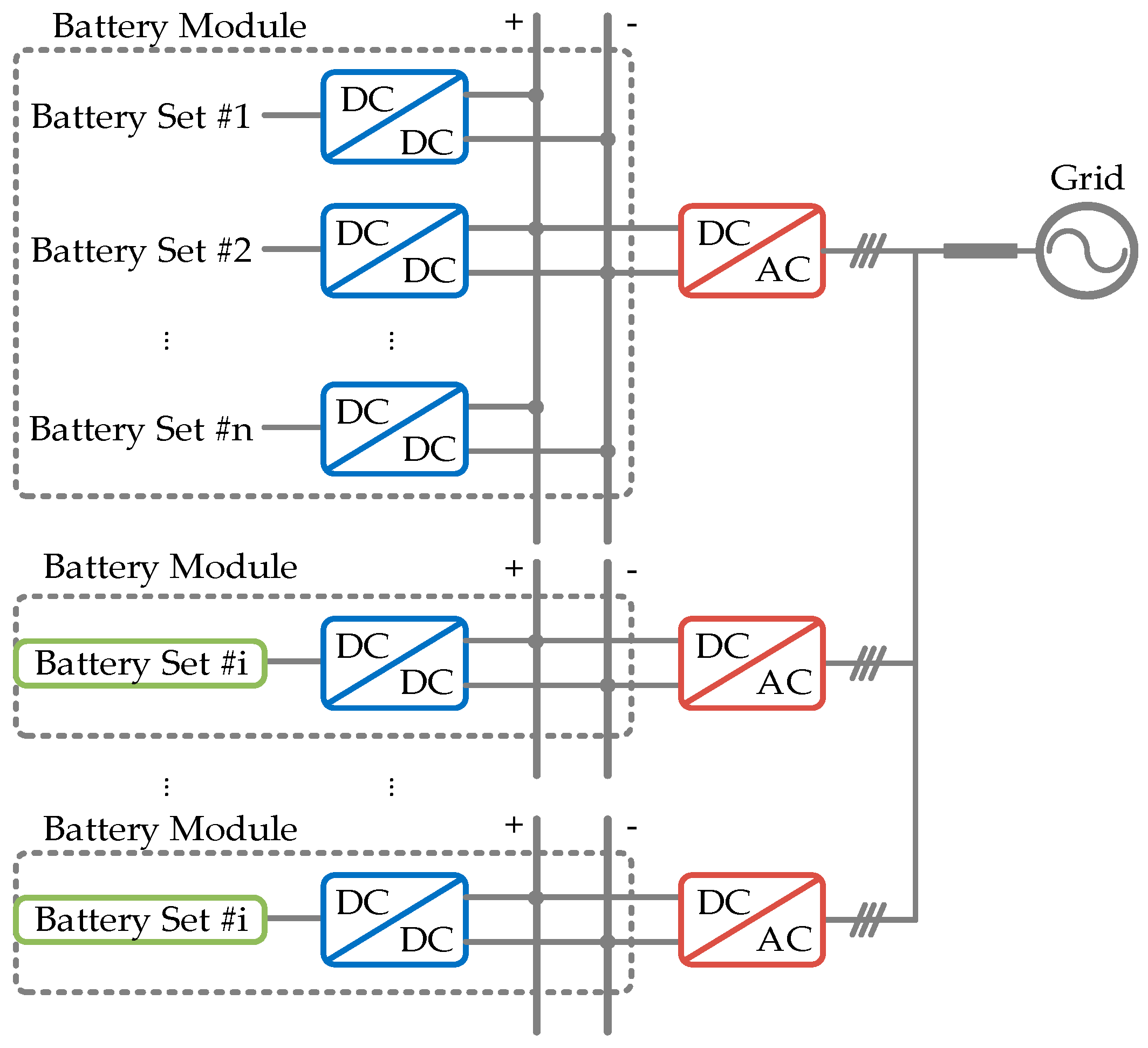
As mentioned above in Section 1, the proposed BESS features a two-stage and modular configuration. In particular, as shown in Figure 1, in Stage I of the BESS, battery sets #1–#n are aggregated in a local module, where a BMS is designed to achieve localized control of multiple batteries, as highlighted in the gray box. Similarly, the other battery modules are also composed of multiple battery sets and each battery module is equipped with a BMS for local control. For each battery set in a particular module, to achieve a controllable operation, it is interfaced with a DC/DC converter, also as shown in Figure 1 as highlighted in blue. Note that each battery module has multiple battery sets dispersedly integrated at the input side of the corresponding DC/DC converter. Meanwhile, all the batteries share a common DC link at the output side of the DC/DC converter. As shown in Figure 1, the functionalities of the BMS for each battery module include: (1) online monitoring of the status of each battery set inside a battery module; (2) charging and discharging coordination of the battery sets; and (3) SoC balancing of multiple battery sets.
On the other hand, in Stage II of the BESS, it should be mentioned that only one DC/AC inverter is used as the PCS for each battery module. For example, for the top module in Figure 1, a PCS (i.e., a DC/AC inverter), highlighted in red, is designed to coordinate the grid interactive operation. The input of each PCS is the common DC link at the output side of each battery module, and its output side is connected to the grid or the PCC of a microgrid. Meanwhile, also as shown in Figure 1, the function of the PCS includes: (1) grid-connected current control; (2) local voltage regulation; and (3) stability enhancement based on virtual impedance. The additional virtual impedance loop is designed to mitigate the impacts of resonance issues in the microgrid with multiple battery modules and thereby multiple PCSs.
3. Control Diagram of Two-Stage BESS
3.1. Control System Design in Stage I
As indicated in Section 2, Stage I in the proposed two-stage BESS is responsible for managing and controlling the batteries in a regional battery module. In particular, the proposed control diagram is designed and implemented to not only achieve conventional local battery voltage and current control, but also realize SoC balancing in each battery module. The conventional local voltage and current control are implemented using a traditional proportional-integral (PI) controller, while the SoC balancing is achieved based on an average-based control scheme. For each battery module, the SoC of each battery set is measured and monitored, and their average is calculated in the decentralized controller of each DC/DC interface inverter. The control objective is to guarantee that the average of all SoC values is equal to that of each SoC. Therefore, the final goal is to equalize the SoC values of each battery set.
Given the slow dynamics of SoC, the average-based control loop is designed as the outer loop of the overall control diagram. In the meantime, the output of the average-based SoC control loop is fed into the inner voltage and current cascaded control loops as an add-on term. Therefore, the emerging control objective (i.e., to balance the SoC of each battery set) and the conventional control object (i.e., voltage and current control) can be obtained simultaneously. The detailed control diagram is shown in Figure 2.
Based on the control diagram detailed in Figure 2, it can be derived that:
where SoCk is the state-of-charge of the kth battery set, Gpisoc is the PI controller of the SoC average controller, vdc* is the reference value of the DC link voltage, vdc is the actual DC link voltage, Gpiv is the PI controller of the voltage control loop, and idc* is the reference voltage of the DC link current.
Since the proposed additional control loop is implemented based on the average SoC, it should be noted that:
where SoCi and SoCj are the state-of-charge of the neighboring units of the corresponding battery set.
Note that to release the communication stress, it is not necessary to use a global communication network and cover all of the point-to-point communication channels among all of the active nodes.
Since multi-loop control diagram is used in Stage I, in order to stabilize the whole system without violating the dynamic operation performance, the interactions between different sections in the converter systems should be finely designed. In other words, it is necessary to adjust the output impedances of the converters in Stage I and the input impedance of the inverter in Stage II to satisfy the Middlebrook criteria [30,31]. It is worth mentioning that the stability criteria is established based on the comparison of output and input impedances as per the requirements in Middlebrook criteria. Therefore, two cutting frequencies are defined, as flow and fhigh, which are used to represent the two intersection frequencies when comparing the output and input impedances in the frequency domain. If denoting the output and input impedances as |ZoS| and |ZiL|, respectively, the stability criteria can be represented as below:
where and are phase angles of ZoS and ZiL, respectively, and (3) should be satisfied between flow and fhigh.
In order to further expand the operation range of the proposed two-stage BESS, a virtual impedance is deployed at the input terminal of the inverter in Stage II. Note that this virtual impedance at Stage II is not regulated within a very large range. It is only adjustable between the frequency boundaries of flow and fhigh. The goal of involving this virtual impedance is to guarantee that the equivalent output impedance and input impedance between Stage I and Stage II meet the requirements as set forth in (3).
By adding the additional virtual impedance in the input side of the inverter at Stage II, it can be derived that the equivalent virtual input impedance is shown as:
where ZiL is the original input impedance, Zvi is the virtual impedance, and ZiL′ is the modified virtual impedance.
To implement the virtual impedance at the input side of the inverter, the reference of DC link voltage can be modified to equivalently manipulate the input impedance, which yields:
where Gin is the transfer function equivalently involved in the DC-link voltage loop, and Gloopd, Gvd, Gpwmd, and Gid are the transfer functions used in the control diagrams of the downstream inverters. Among them, Gvd and Gid are the voltage and current loops, Gloopd is the original loop gain of the original control loop, and Gpwmd is the pulse width modulation (PWM) delay.
In (5), the transfer function Gin is used to indirectly implement the virtual impedance by changing the DC link voltage reference. The reason for this is that, by re-orienting the control implementation into DC link voltage rather than using DC link input current directly, the proposed control diagram can be easily integrated with the DC-link voltage controller. Meanwhile, there are commonly rich disturbances and switching oscillations in the DC link current. Using the DC link voltage, it is possible to stabilize the system more easily, without being influenced by the high-frequency harmonics.
3.2. Control System Design in Stage II
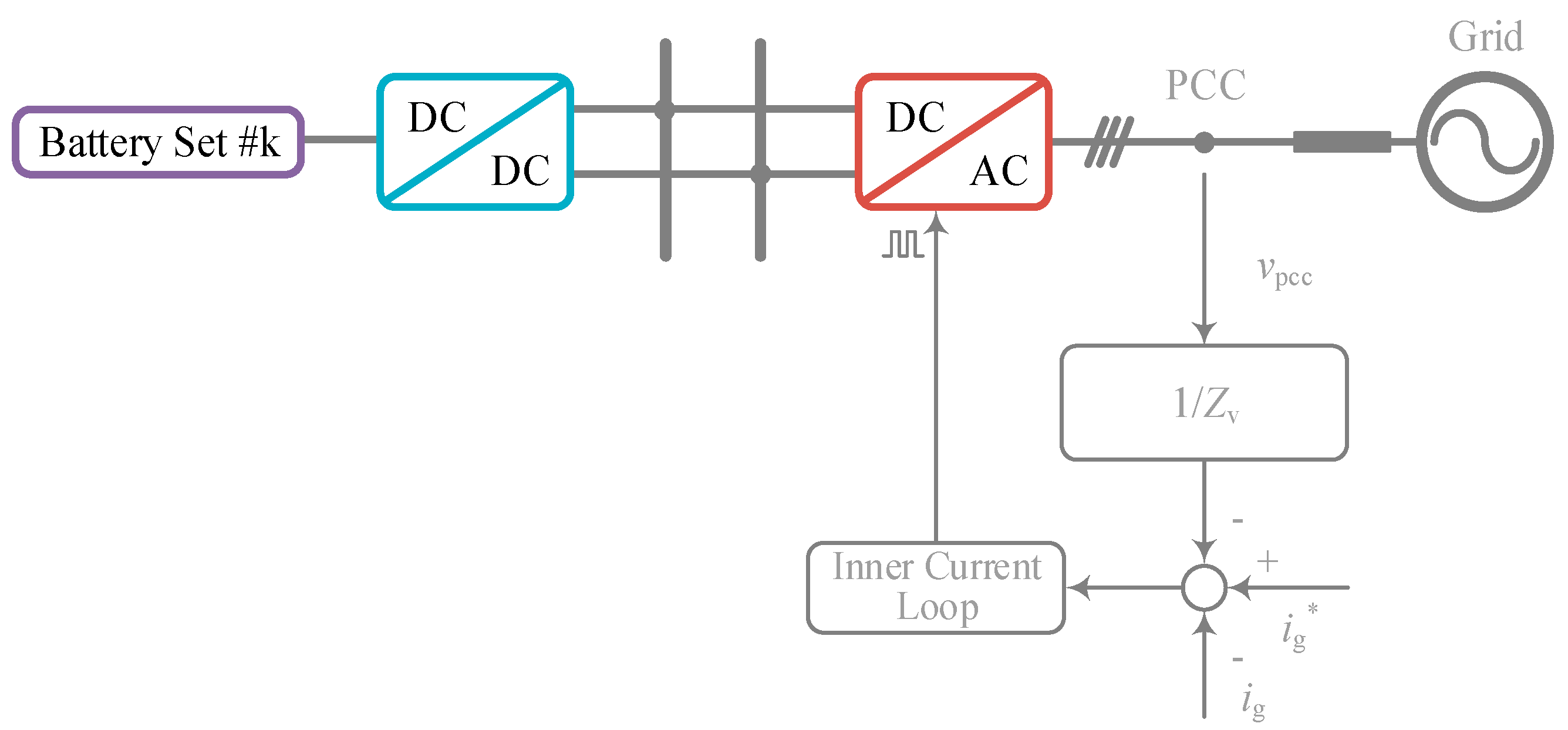
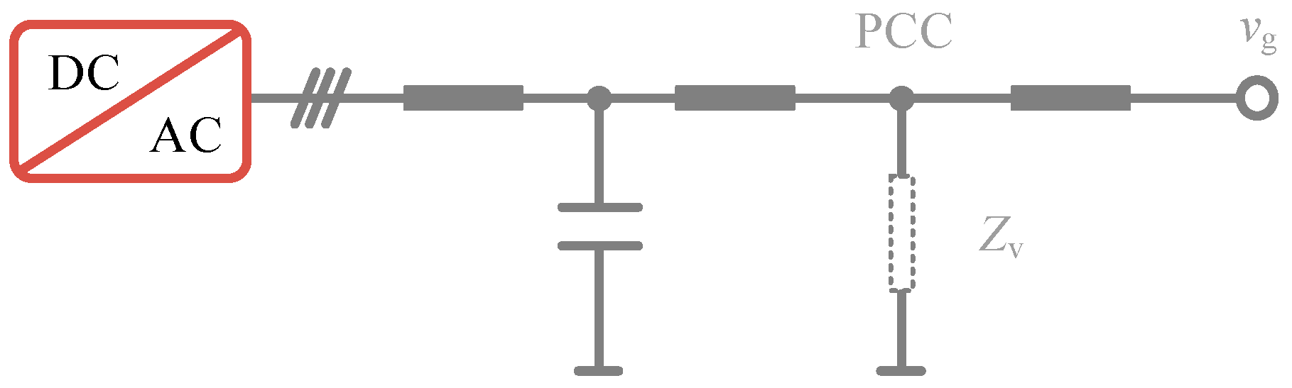
As mentioned above, each battery module is associated with a PCS to achieve a stable power exchange between the BESS and the external grid or the PCC of a microgrid. In addition to the traditional control loops, as shown in Figure 3, which are designed for voltage and current control, an extra virtual impedance loop is employed to facilitate the integration of multiple PCSs at the common coupling and to mitigate the impacts induced by instabilities. Note that the proposed virtual impedance loop is implemented based on PCC voltage feedback. By inserting the virtual impedance loop, it is equivalent to adding a physical resistor at the PCC, as shown in Figure 4.
The overall control diagram of multiple PCSs can be regarded as a multiple input multiple output (MIMO) system. Based on the circuit interaction, it can be noted that multiple PCSs are coupled at the PCC, which means that the multiple output terminals of the MIMO system are coupled as well. To better understand the interactions among multiple outputs of the MIMO system and design the corresponding virtual impedance loops, the MIMO system can be implemented below:
Simplifying (6), it yields that:
where
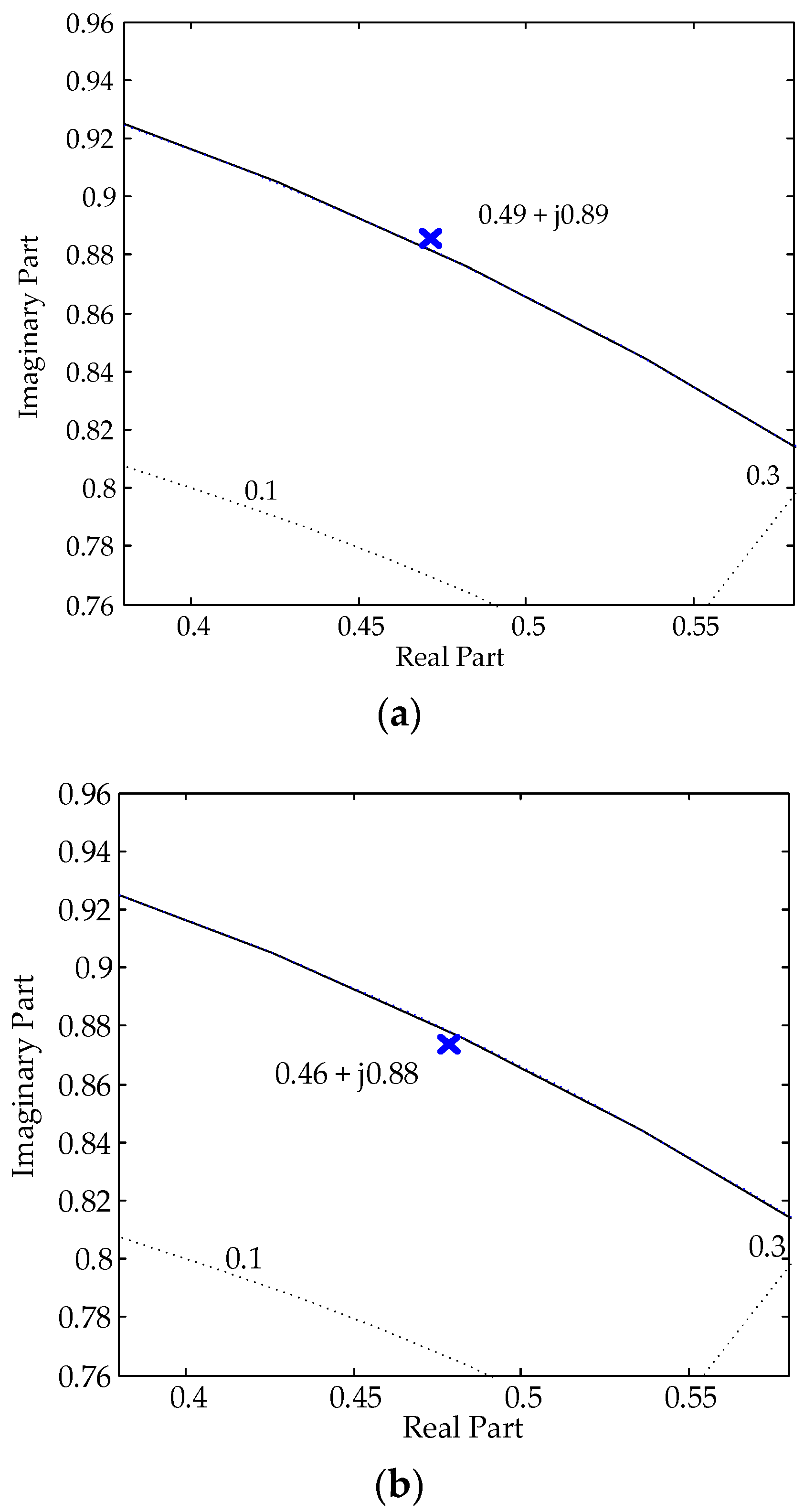
Note that Gcontrol represents the inner control loops. Therefore, by using the aggregated transfer function (7), the transfer functions from the reference value of the grid-connected current to the actual grid-connected current can be obtained. Therefore, the frequency domain analysis can be obtained by analyzing the corresponding transfer functions in (7) in the z-domain. Taking the transfer function from Ig1* to Ig1 as an example, the derived bode plot is shown in Figure 5a. Here, the Tustin discretization is used, as shown below:
where Tpwm is the PWM delay.
Note that the z-domain stability analysis results show that there is a pair of unstable poles, which are 0.49 ± j 0.89. Here, a zoom-in result is shown in Figure 5a since the positive and negative planes are symmetric. The poles are indicated by the blue cross. It is observed that this pair of poles is located outside the unit circuit, which indicates that the system is unstable.
After activating the additional virtual impedance loops, it is noticed that the unstable poles move into the unit circuit, which indicates that the system is stable. Therefore, the effectiveness of the proposed method can be validated.
3.3. Charging and Discharging Coordination
Considering both charging and discharging operations, it is necessary to discuss and ensure that safe operation can be guaranteed in both of the above processes. The charging and discharging of multiple battery sets are coordinated following the two-stage architecture.
In Stage I, the charging and discharging procedures are coordinated and implemented using the additional average-based SoC control loop, which means that the SoC is balanced in each battery module. Therefore, the charging and discharging process can be coordinated with the SoC of each battery set balanced. In other words, with a balanced SoC in each battery set, neither the over-charging nor the over-discharging procedure will be triggered. On the other hand, in Stage II, the charging and discharging of multiple battery modules are coordinated in the PCSs. The direction of power flow in the multiple PCSs are determined based on the grid-side dispatch command. When the whole BESS is requested to provide active power support, multiple PCSs are controlled simultaneously to support power (i.e., operated with power flowing from the BESS to the external grid); when the whole BESS is requested to absorb active power, multiple PCSs are controlled to absorb power instead (i.e., operated with power flowing from the external grid to the BESS).
4. Simulation Validation
In order to verify the proposed two-stage BESS and the corresponding control diagram, a comprehensive simulation model is established in MATLAB/Simulink (MATLAB2015a, MathWorks, Natick, MA, USA). For Stage I, there are two battery modules, and each battery module includes two battery sets. Meanwhile, for Stage II, there are two PCS, which are connected to each battery module. In other words, each PCS is connected to a battery module. The diagram of the test system is represented in Figure 6 and the system parameters are shown in Table 1. Note that LCL filters are used for PCS inverters. The typical design procedure of the LCL filter is listed as follows. Step 1: The inverter-side inductance is selected to minimize the current ripple in the inverter output current waveform; Step 2: The filter capacitance is selected to maintain a sufficient damping ratio at the high-frequency range, i.e., to ensure a sufficient stability margin; Step 3: The grid-side inductance is selected after Steps 1 and 2 to further suppress the steady-state error in the grid-connected current [32]. Meanwhile, the DC-link capacitance of the PCS inverter is 650 μF, which is determined by considering the maximum ripple voltage as well as the power balance between DC and AC sides of the inverter so that the AC-side voltage can be held up temporarily even though the AC grid voltage is interrupted.
Two test scenarios are considered, including SoC balancing among multiple ESUs at Stage I and stable power conditioning at Stage II.
Case I: SoC Balancing among Multiple ESUs at Stage I
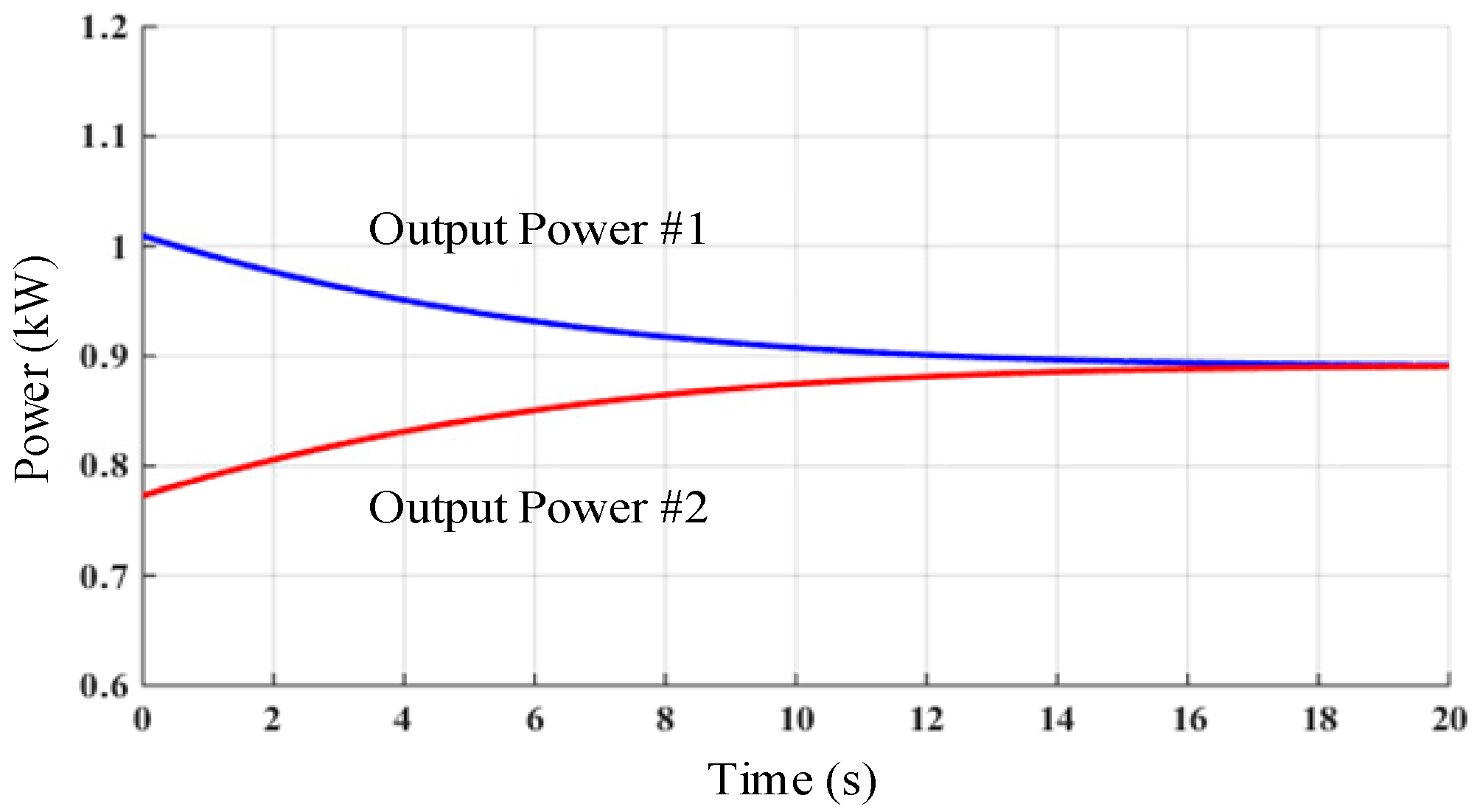
Considering the same control diagram in Modules #1 and #2, Module #1 is taken as an example (i.e., the top half section of the circuits in Figure 6), as shown in Figure 7, Figure 8, Figure 9 and Figure 10, the SoC of each ESU is balanced in both charging and discharging processes. In Figure 7, with decreasing SoC, since the average of the SoCs are controlled, they gradually become equal to each other, while as shown in Figure 9, on the other hand, in the charging process, with increasing SoC, since the average of all the two SoCs are controlled, they also gradually become equal. Note that the curve of SoC1/SoC2 is shown in these two figures to highlight that the SoC of each battery set is gradually equalized. Meanwhile, the corresponding waveforms of the discharging and charging power are shown in Figure 8 and Figure 10, respectively.
Case II: Power Conditioning at Stage II
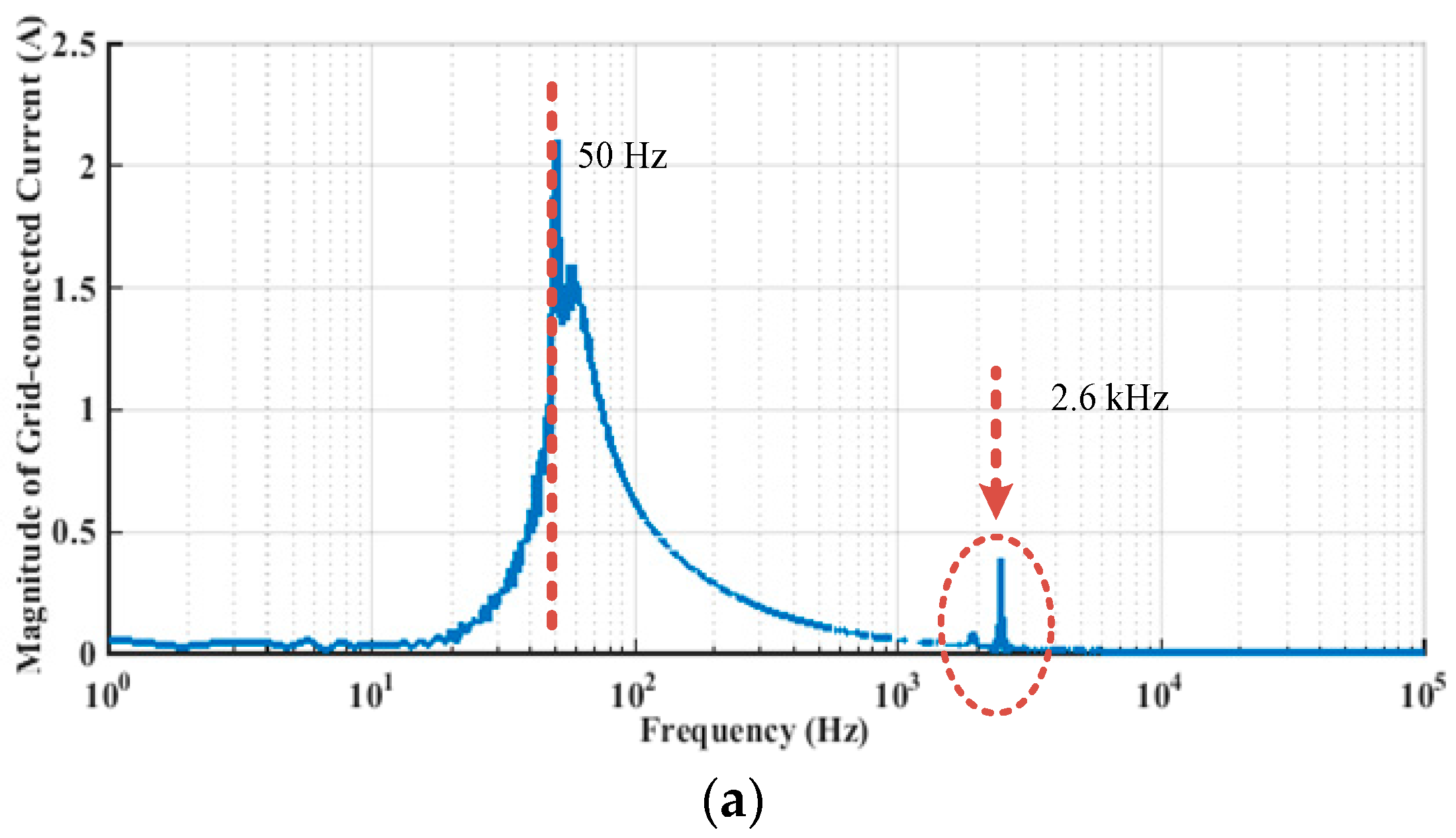
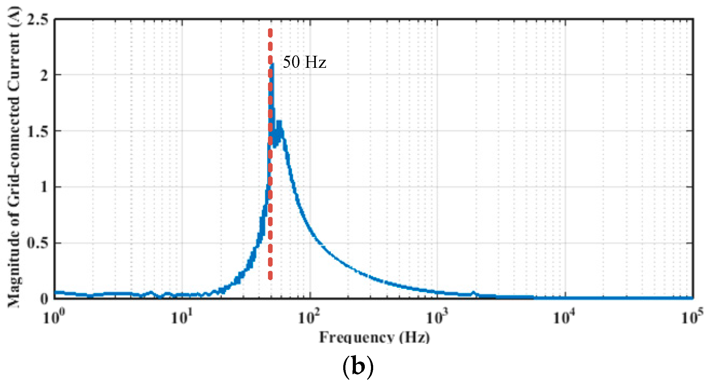
To test the performance of Stage II of the proposed BESS system, the grid-connected current and the output power are tested. As shown in Figure 11, the grid-connected current of PCS #1 is shown. If an additional virtual impedance loop is not activated, as shown in Figure 11a, there are high-frequency oscillations in the grid-connected current, which are induced by the resonance peaks. However, if the virtual impedance loop is activated, as shown in Figure 11b, the high-frequency oscillations disappear in the current waveforms, which indicates a stable operating system. The corresponding Fast Fourier Transform (FFT) analysis results are shown in Figure 12a,b, respectively, to highlight the effectiveness of the proposed stability improvement method. It can be seen that before applying the virtual impedance, the instability issues mainly involve the distortion at the frequency of approximately 2.6 kHz, as shown in Figure 12a. However, after applying the virtual impedance, the distortion at this frequency is highly attenuated, as shown in Figure 12b.
5. Conclusions
In this paper, a two-stage BESS is designed and implemented. In Stage I, a modular design is implemented to aggregate multiple battery sets and one BMS is associated with one aggregated battery module; in Stage II, one PCS is used to connect each aggregated battery module to the external grid or PCC of a microgrid. By using the above modular BESS, less BMSs and PCSs are used, so the system cost can be lowered. Meanwhile, from the inverter control standing point, SoC balancing is achieved in each aggregated battery module to equalize the charging and discharging power among multiple battery sets. Meanwhile, an extra virtual impedance loop is employed to facilitate the integration of multiple PCSs in Stage II so that resonance issues can be mitigated.
Author Contributions
All authors contributed to this work by collaboration. Bing Xie designed and developed the main research work, including designing the controller, simulation model, analyses of the obtained results and writing the paper. Yiqi Liu, Yanchao Ji and Jianze Wang provided some useful suggestions in the construction of the paper. All authors revised and approved the publication.
Conflicts of Interest
The authors declare no conflict of interest.
References
- Agrawal, R.; Jain, S. Multilevel inverter for interfacing renewable energy sources with low/medium- and high-voltage grids. IET Renew. Power Gener. 2017, 11, 1822–1831. [Google Scholar] [CrossRef]
- Leithon, J.; Sun, S.; Lim, T.J. Demand response and renewable energy management using continuous-time optimization. IEEE Trans. Sustain. Energy 2017. [Google Scholar] [CrossRef]
- Xiaodong, L. Emerging power quality challenges due to integration of renewable energy sources. IEEE Trans. Ind. Appl. 2017, 53, 855–866. [Google Scholar]
- Bose, B.K. Power Electronics, Smart Grid, and Renewable Energy Systems. Proc. IEEE 2017, 105, 2011–2018. [Google Scholar] [CrossRef]
- Reynolds, M.; Stidham, D.; Alaywan, Z. The Golden Spike: Advanced power electronics enables renewable development across NERC regions. IEEE Power Energy Mag. 2012, 10, 71–78. [Google Scholar] [CrossRef]
- Montanari, G.C. Time behavior of partial discharges and life of type II turn insulation specimens under repetitive impulse and sinusoidal waveforms. IEEE Electr. Insul. Mag. 2017, 33, 17–26. [Google Scholar] [CrossRef]
- Baimel, D.; Belikov, J.; Guerrero, J.M.; Levron, Y. Dynamic modeling of networks, microgrids, and renewable sources in the dq0 reference frame: A Survey. IEEE Access 2017, 5, 21323–21335. [Google Scholar] [CrossRef]
- Tushar, M.H.K.; Assi, C. Optimal energy management and marginal-cost electricity pricing in microgrid network. IEEE Trans. Ind. Inform. 2017, 13, 3286–3298. [Google Scholar] [CrossRef]
- Vahedipour-Dahraie, M.; Rashidizadeh-Kermani, H.; Najafi, H.R.; Anvari-Moghaddam, A.; Guerrero, J.M. Stochastic security and risk-constrained scheduling for an autonomous microgrid with demand response and renewable energy resources. IET Renew. Power Gener. 2017, 11, 1812–1821. [Google Scholar] [CrossRef]
- Lin, Y.; Dong, P.; Sun, X.; Liu, M. Two-level game algorithm for multi-microgrid in electricity market. IET Renew. Power Gener. 2017, 11, 1733–1740. [Google Scholar] [CrossRef]
- Akram, U.; Khalid, M.; Shafiq, S. An innovative hybrid wind-solar and battery-supercapacitor microgrid system—Development and optimization. IEEE Access 2017, 5, 25897–25912. [Google Scholar] [CrossRef]
- Asensio, M.; Contreras, J. Stochastic unit commitment in isolated systems with renewable penetration under CVaR assessment. IEEE Trans. Smart Grid 2016, 7, 1356–1367. [Google Scholar] [CrossRef]
- Chen, Z.; Wu, L.; Shahidehpour, M. Effective load carrying capability evaluation of renewable energy via stochastic long-term hourly based SCUC. IEEE Trans. Sustain. Energy 2015, 6, 188–197. [Google Scholar] [CrossRef]
- Wu, H.; Shahidehpour, M.; Alabdulwahab, A.; Abusorrah, A. Demand response exchange in the stochastic day ahead scheduling with variable renewable generation. IEEE Trans. Sustain. Energy 2015, 6, 516–525. [Google Scholar] [CrossRef]
- Bitaraf, H.; Rahman, S. Reducing curtailed wind energy through energy storage and demand response. IEEE Trans. Sustain. Energy 2018, 9, 228–236. [Google Scholar] [CrossRef]
- Alharbi, H.; Bhattacharya, K. Stochastic optimal planning of battery energy storage systems for isolated microgrids. IEEE Trans. Sustain. Energy 2018, 9, 211–227. [Google Scholar] [CrossRef]
- Vavilapalli, S.; Subramaniam, U.; Padmanaban, S.; Ramachandaramurthy, V.K. Design and real-time simulation of an AC voltage regulator based battery charger for large-scale PV-grid energy storage systems. IEEE Access 2017, 5, 25158–25170. [Google Scholar] [CrossRef]
- Luna, A.C.; Diaz, N.L.; Graells, M.; Vasquez, J.C.; Guerrero, J.M. Mixed-integer-linear-programming-based energy management system for hybrid PV-wind-battery microgrids: modeling, design, and experimental verification. IEEE Trans. Power Electron. 2017, 32, 2769–2783. [Google Scholar] [CrossRef]
- Tedesco, F.; Mariam, L.; Basu, M.; Casavola, A.; Conlon, M.F. Economic model predictive control-based strategies for cost-effective supervision of community microgrids considering battery lifetime. IEEE J. Emerg. Sel. Top. Power Electron. 2015, 3, 1067–1077. [Google Scholar] [CrossRef]
- Zhang, Z.; Cai, Y.Y.; Zhang, Y.; Gu, D.J.; Liu, Y.F. A distributed architecture based on microbank modules with self-reconfiguration control to improve the energy efficiency in the battery energy storage system. IEEE Trans. Power Electron. 2016, 31, 304–317. [Google Scholar] [CrossRef]
- Zhu, Q.; Li, L.; Hu, X.; Xiong, N.; Hu, G.D. H-infinity-based nonlinear observer design for state of charge estimation of lithium-ion battery with polynomial parameters. IEEE Trans. Veh. Technol. 2017, 66, 10853–10865. [Google Scholar] [CrossRef]
- Lu, X.; Sun, K.; Guerrero, J.M.; Vasquez, J.C.; Huang, L. Double-quadrant state-of-charge-based droop control method for distributed energy storage systems in autonomous DC microgrids. IEEE Trans. Smart Grid 2015, 6, 147–157. [Google Scholar] [CrossRef]
- Fantino, R.A.; Busada, C.A.; Solsona, J.A. Optimum PR control applied to LCL filters with low resonance frequency. IEEE Trans. Power Electron. 2018, 33, 793–801. [Google Scholar] [CrossRef]
- Ghoshal, A.; John, V. Active damping of LCL filter at low switching to resonance frequency ratio. IET Power Electron. 2015, 8, 574–582. [Google Scholar] [CrossRef]
- Zou, Z.; Wang, Z.; Cheng, M. Modeling, analysis, and design of multifunction grid-interfaced inverters with output LCL filter. IEEE Trans. Power Electron. 2014, 29, 3830–3839. [Google Scholar] [CrossRef]
- Wang, X.; Blaabjerg, F.; Wu, W. Modeling and analysis of harmonic stability in an AC power-electronics-based power system. IEEE Trans. Power Electron. 2014, 29, 6421–6432. [Google Scholar] [CrossRef]
- He, J.; Li, Y.W.; Bosnjak, D.; Harris, B. Investigation and active damping of multiple resonances in a parallel-inverter-based microgrid. IEEE Trans. Power Electron. 2013, 28, 234–246. [Google Scholar] [CrossRef]
- Wang, X.; Blaabjerg, F.; Liserre, M.; Chen, Z.; He, J.; Li, Y.W. An active damper for stabilizing power-electronics-based AC systems. IEEE Trans. Power Electron. 2014, 29, 3318–3329. [Google Scholar] [CrossRef]
- Wang, X.; Pang, Y.; Loh, P.C.; Blaabjerg, F. A series-LC-filtered active damper with grid disturbance rejection for AC power-electronics-based power systems. IEEE Trans. Power Electron. 2015, 30, 4037–4041. [Google Scholar] [CrossRef]
- Riccobono, A.; Santi, E. Comprehensive review of stability criteria for DC distribution systems. In Proceedings of the IEEE Energy Conversion Congress and Exposition (ECCE), Raleigh, NC, USA, 15–20 September 2012; pp. 3917–3925. [Google Scholar]
- Zhang, X.; Zhong, Q.C.; Ming, W.L. Stabilization of a cascaded DC converter system via adding a virtual adaptive parallel impedance to the input of the load converter. IEEE Trans. Power Electron. 2016, 31, 1826–1832. [Google Scholar] [CrossRef]
- Bao, C.; Ruan, X.; Wang, X.; Li, W.; Pan, D.; Weng, K. Step-by-Step controller design for LCL-type grid-connected inverter with capacitor–current-feedback active-damping. IEEE Trans. Power Electron. 2014, 29, 1239–1253. [Google Scholar]
Figure 1.
Configuration of the two-stage battery energy storage system (BESS).

Figure 2.
Control diagram of Stage I: average-based state-of-charge (SoC) balancing and conventional DC voltage and current control loops.
Figure 2.
Control diagram of Stage I: average-based state-of-charge (SoC) balancing and conventional DC voltage and current control loops.
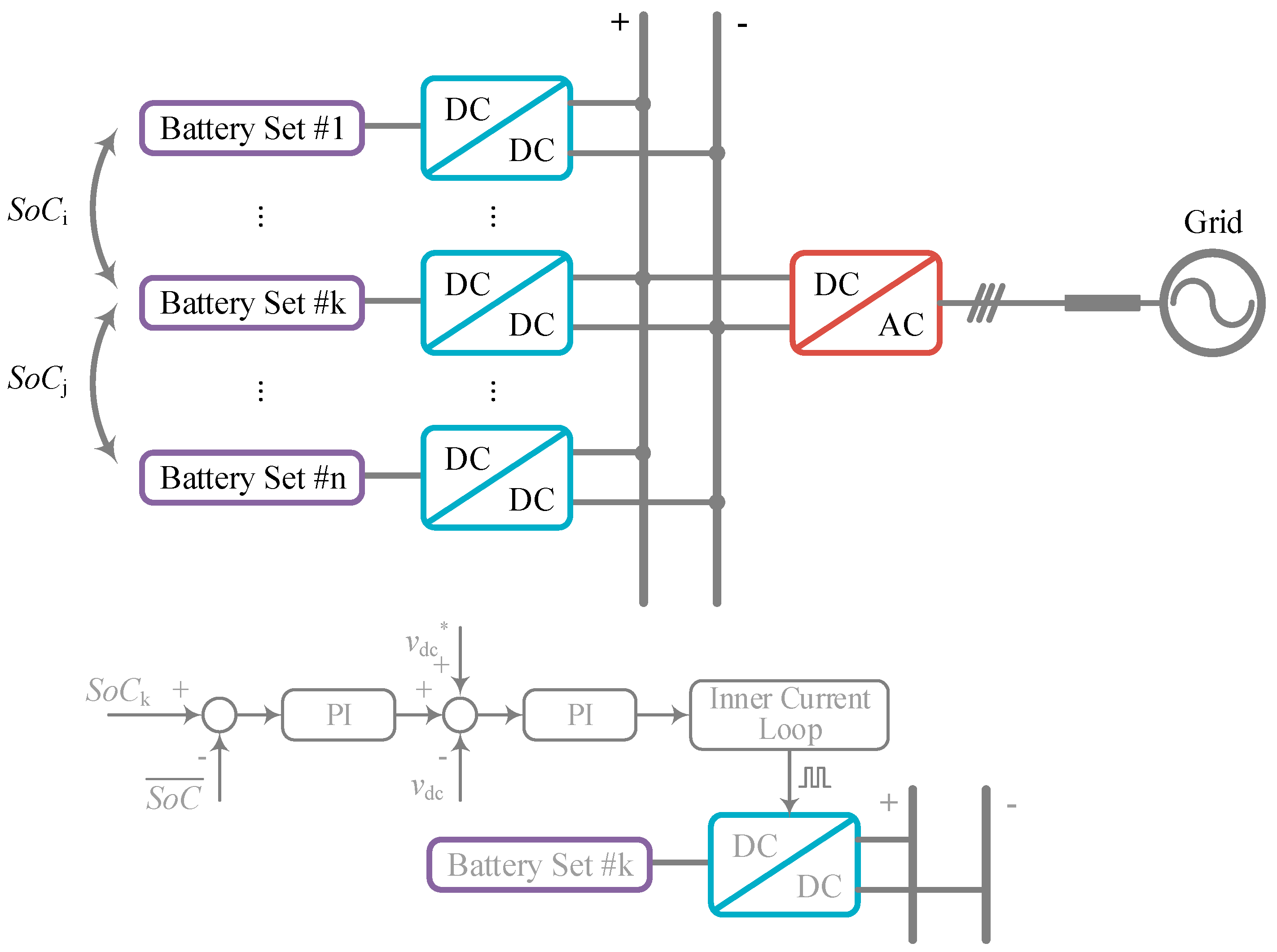
Figure 3.
Control diagram of the power conditioning system (PCS).

Figure 4.
Virtual impedance equivalently connected at the capacitor branch.

Figure 5.
Z-domain analysis of the transfer from Ig1* to Ig1: (a) unstable (b) stable.

Figure 6.
Two-stage BESS test system.
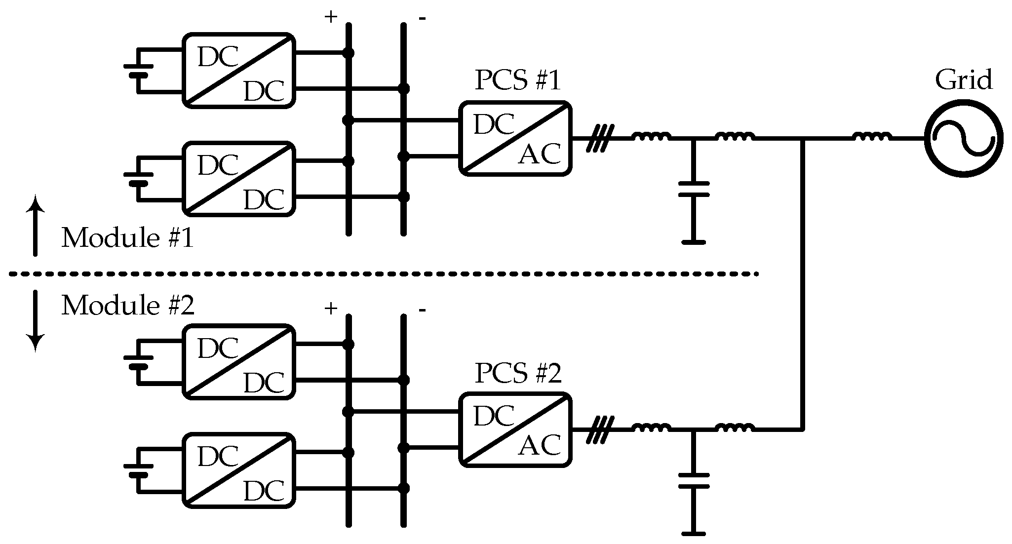
Figure 7.
Decreasing SoC in the discharging process.
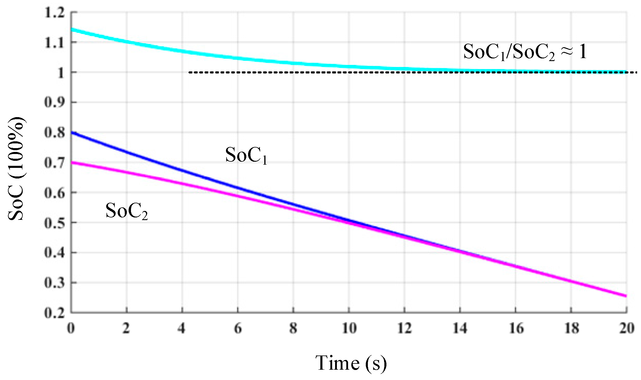
Figure 8.
Waveforms of discharging power.

Figure 9.
Increasing SoC in the charging process.

Figure 10.
Waveforms of charging power.

Figure 11.
Grid-connected current without or with the additional virtual impedance loop: (a) without virtual impedance loop; (b) with virtual impedance loop.
Figure 11.
Grid-connected current without or with the additional virtual impedance loop: (a) without virtual impedance loop; (b) with virtual impedance loop.
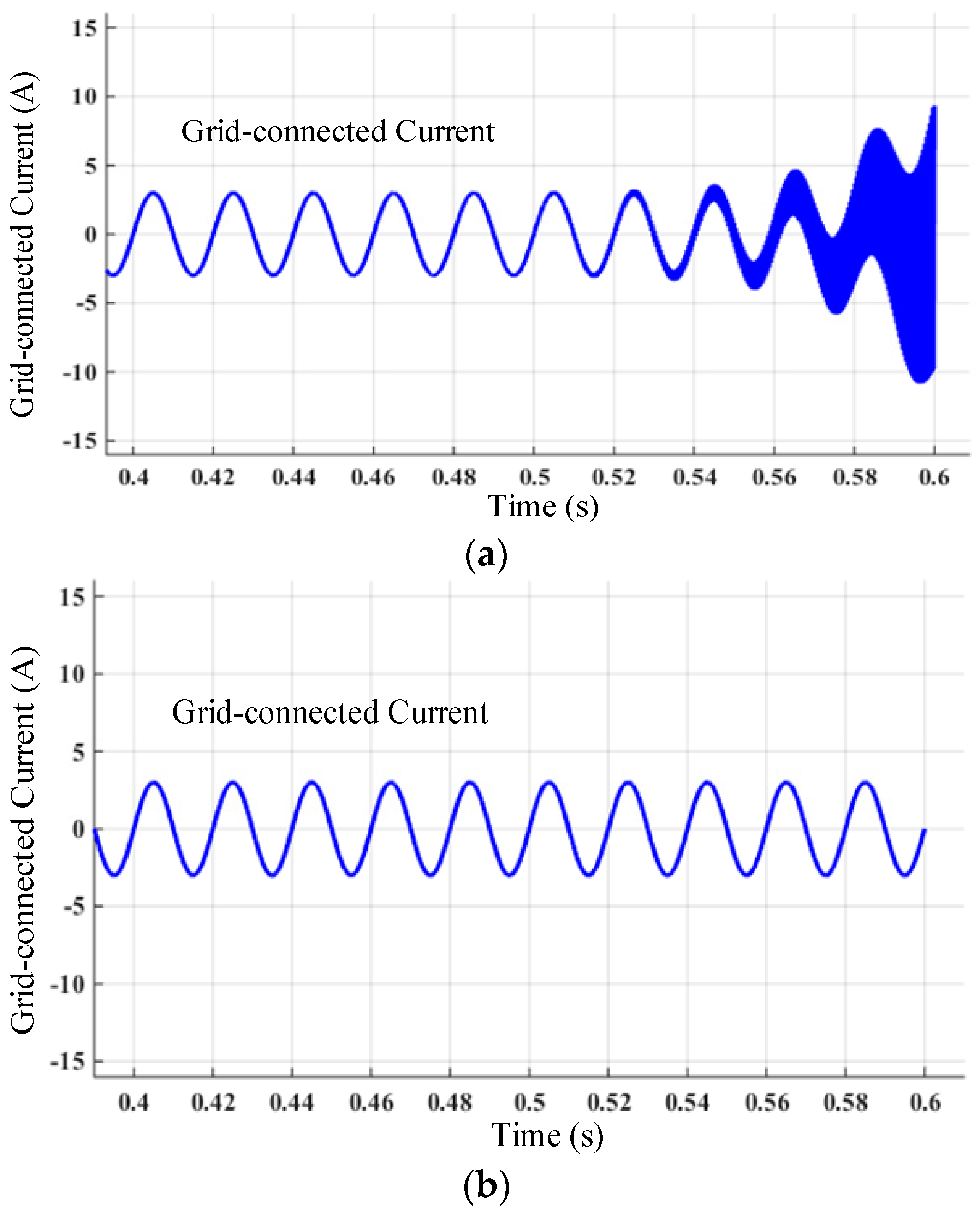
Figure 12.
Fast Fourier Transform (FFT) analysis results of the grid-connected current without or with the additional virtual impedance loop: (a) without virtual impedance loop; (b) with virtual impedance loop.
Figure 12.
Fast Fourier Transform (FFT) analysis results of the grid-connected current without or with the additional virtual impedance loop: (a) without virtual impedance loop; (b) with virtual impedance loop.


Table 1.
System parameters.
| Item | Value |
|---|---|
| Battery voltage (input voltage of battery converter) | 120 V |
| Common DC bus voltage (output voltage of battery converter) | 640 V |
| Nominal power of each battery converter | 1 kW |
| Normal power of PCS | 2.5 kW |
| LCL filter of PCS: inverter side inductance | 2 mH |
| LCL filter of PCS: grid side inductance | 2 mH |
| LCL filter of PCS: capacitance | 4 μF |
| DC-link capacitance | 650 μF |
| Grid impedance | 3 mH |
| Grid voltage(phase to neutral point voltage) | 220 V |
| Grid frequency | 50 Hz |
| Initial SoC (discharging) for Module #1 and #2 | 80% and 70% |
| Initial SoC (charging) for Module #1 and #2 | 20% and 30% |
© 2018 by the authors. Licensee MDPI, Basel, Switzerland. This article is an open access article distributed under the terms and conditions of the Creative Commons Attribution (CC BY) license (http://creativecommons.org/licenses/by/4.0/).
Share and Cite
MDPI and ACS Style
Xie, B.; Liu, Y.; Ji, Y.; Wang, J. Two-Stage Battery Energy Storage System (BESS) in AC Microgrids with Balanced State-of-Charge and Guaranteed Small-Signal Stability. Energies 2018, 11, 322. https://doi.org/10.3390/en11020322
AMA Style
Xie B, Liu Y, Ji Y, Wang J. Two-Stage Battery Energy Storage System (BESS) in AC Microgrids with Balanced State-of-Charge and Guaranteed Small-Signal Stability. Energies. 2018; 11(2):322. https://doi.org/10.3390/en11020322
Chicago/Turabian StyleXie, Bing, Yiqi Liu, Yanchao Ji, and Jianze Wang. 2018. "Two-Stage Battery Energy Storage System (BESS) in AC Microgrids with Balanced State-of-Charge and Guaranteed Small-Signal Stability" Energies 11, no. 2: 322. https://doi.org/10.3390/en11020322
Note that from the first issue of 2016, this journal uses article numbers instead of page numbers. See further details here.