A Comparative Study on Controllers for Improving Transient Stability of DFIG Wind Turbines During Large Disturbances


1
Department of Electrical Engineering, The University of Da Nang- University of Science and Technology, Block A, 54 Nguyen Luong Bang Street, LienChieu District, DaNang 550000, Vietnam
2
Dipartimento di Energia, Politecnico di Milano, via La Masa 34, 20156 Milano, Italy
*
Authors to whom correspondence should be addressed.
†
These authors contributed equally to this work.
Energies 2018, 11(3), 480; https://doi.org/10.3390/en11030480
Submission received: 31 December 2017
/
Revised: 17 February 2018
/
Accepted: 19 February 2018
/
Published: 25 February 2018
(This article belongs to the Special Issue Wind Generators Modelling and Control)
Abstract
:Under power system short-circuits, the Doubly-Fed Induction Generator (DFIG) Wind Turbines (WT) are required to be equipped with crowbar protections to preserve the lifetime of power electronics devices. When the crowbar is switched on, the rotor windings are short-circuited. In this case, the DFIG behaves like a squirrel-cage induction generator (SCIG) and can adsorb reactive power, which can affect the power system. A DFIG based-fault-ride through (FRT) scheme with crowbar, rotor-side and grid-side converters has recently been proposed for improving the transient stability: in particular, a hybrid cascade Fuzzy-PI-based controlling technique has been demonstrated to be able to control the Insulated Gate Bipolar Transistor (IGBT) based frequency converter in order to enhance the transient stability. The performance of this hybrid control scheme is analyzed here and compared to other techniques, under a three-phase fault condition on a single machine connected to the grid. In particular, the transient operation of the system is investigated by comparing the performance of the hybrid system with conventional proportional-integral and fuzzy logic controller, respectively. The system validation is carried out in Simulink, confirming the effectiveness of the coordinated advanced fuzzy logic control.
1. Introduction
The presence of renewable energy among conventional energy resources is increasing day by day. There are several renewable sources like wind, solar, fuel cell and bio-gas, which are getting popular, and more investments are now focused in the renewable energy sector. In this context, wind energy is one of the most relevant sources due to its enormous potential to play a significant role in the energy market. As per recent statistics, wind power has reached a total of 370 GW of global capacity, with an increase of nearly 170 GW in the past five years. Wind penetration is expected to reach 60 GW per year by 2018 [1].
The rapidly increasing integration of wind energy in the power system networks has driven many research activities on the topics of stability, power quality, energy-efficiency and reliable forecasting [2]. Artificial intelligence techniques have been successfully applied for designing, planning, sizing, optimizing and forecasting the renewable energy sources [3,4,5], for neural networks based forecasting of energy production and consumption [6], and fuzzy systems for control strategies [7,8,9].
In particular, in order to increase power quality and grid stability with large wind farms, specific technical requirements have been elaborated upon and included in the grid codes issued by the Transmission System Operators (TSOs) of many countries [10]. The search for grid code compliance drove the adoption of variable-speed technologies, especially (Doubly-Fed Induction Generator) DFIG-based wind systems employing a back-to-back converter. DFIG presents many advantages with respect to the traditional squirrel-cage induction generator (SCIG), such as lighter weight, higher output power, variable speed operation, improved efficiency, smaller size, lower cost [11]. These characteristics are mainly due to the control of a rotor side converter (RSC), typically rated at around 25% of the rating of the generator when the rotor speed is in the range of 75%∼125% in normal operating conditions [12]. Hence, the DFIG technology covers about 50% of the wind energy market [13].
Several technical concerns arose about the realization of (fault tide through) FRT for DFIG, since grid faults need to be properly addressed, including the over-current in the stator and rotor circuits, the over-voltage of the DC-link connecting the RSC and the grid side converter (GSC). The reactive power output from DFIG need to be increased as much as possible to meet the challenging requirements of reactive power support during large disturbances. Generally, the existing FRT DFIG solutions can be categorized into two types: the crowbar protection and the demagnetizing method.
The crowbar protection is applied for securing the power converter and rotor windings against over-voltages and over-currents determined by short-circuits in the main grid [14,15,16,17,18]. When the crowbar is inserted, during the short-circuit period, the rotor is in short circuit and the RSC is blocked. Then, the DFIG operates as an SCIG, thus tending to adsorb reactive power from the grid and causing a potential voltage drop. In the past, some papers have proposed a coordinated voltage control to enhance the DFIG wind generator uninterrupted capability during grid faults [19,20]. The main point, when the protection device is triggered, is that the GSC becomes an ancillary source for reactive power, while the RSC is blocked. However, this solution does not show the optimal combination and flexibility between the components yet: in particular, the RSC only returns to normal operation as well as provides reactive power support after clearing fault or removing protection device. As a result, the voltage in DFIG wind farm recovers slowly to pre-fault profile. Obviously, this strategy cannot take full advantage of DFIG power converter capability during grid faults. Moreover, in general, the issue of electro-mechanical oscillations becomes increasingly less significant particularly, at higher wind penetration [21,22].
On the other hand, the demagnetizing method [23,24,25] aims to eliminate transients of the induced electromagnetic force in the rotor circuit by controlling the RSC output to trace and counteract the oscillations of stator flux. However, the industrial implementation of this method is too complex, due to the limitations in converter rating.
Several works previously addressed the DFIG control performance during normal operating conditions [11,26,27]: in this scenario, the conventional DFIG without fault-ride-through capability and the crowbar protects the electronic equipment. This case may lead to system instability, as the RSC is blocked due to crowbar activation and the reactive power control is lost.
Therefore, for improving the fault-ride-through capability, a coordinated control system of crowbar protection, RSC and GSC is investigated through simulations. In [28], a hybrid cascade Fuzzy-PI based controlling technique is introduced to control the Insulated Gate Bipolar Transistor (IGBT) to enhance the transient stability. However, this technique was not validated with respect to other control methods. Indeed, for improving the FRT capability of the DFIG during large disturbance, additional control methods have been suggested in literature. The proportional-integral (PI) has been often used for power regulation [29]. The controlled system shows bad results in terms of response time and precision when the operating points are changed. As a result, the PI controller needs to be redesigned to maintain the system dynamic response and stability. Fuzzy controllers have the advantage that can deal with nonlinear systems and use the human operator knowledge. Fuzzy controller has many parameters: the most critical aspect is to make a good choice of rule base and parameters of membership functions. Once a fuzzy controller is given, the whole system can actually be considered as a deterministic system. When the parameters are well chosen, the response of the system has very good time domain characteristics [30]. For the sake of convenience, the inputs and output of the Fuzzy Logic Controller (FLC) are normalized by coefficients, depending on the base value. These scaling factors can be constant or variable, thus playing an important role in the FLC design to achieve a better response [31].
This paper presents the models developed in Matlab/Simulink for a wind power plant based on DFIG equipped with crowbar protection, tested during high perturbations occurring on the power system. This is achieved with an advanced coordinated fuzzy-proportional-integral control of transistors-based converter for transient stability improvement. The simulation results demonstrate the improved operation of DFIG with the proposed control, compared to conventional DFIG without/with fault-ride-through using conventional proportional-integral and fuzzy controllers, respectively, for fault-ride-through compliance with the current regulations.
The paper is organized as follows: in Section 2 a review of technical requirements of grid code for wind farms is introduced; in Section 3 the test system configuration of wind power plant based DFIG WT (Wind Turbine) connected to the grid is discussed; Section 4 presents the proposed Low-Voltage Ride Through (LVRT) control scheme; in Section 5, results are reported and discussed, and the last section presents the conclusion.
2. European Regulations for Wind Turbines Fault-Ride-Through Compliance
The widespread integration of Renewable Energy Systems (RESs) into the existing power systems is raising technical challenges for voltage regulation [32]. Among RESs interconnected into the power systems, the highest share is represented by wind farms, which must ensure reactive power control for ensuring voltage level support. The current regulations imply that WTs shall not be disconnected from the grid when a fault happens, but they must maintain the voltage level by compensating for reactive power, and then resume to normal operation conditions as soon as the fault is cleared. A time of 150 ms is considered in most of the grid codes for fault clearance by primary protection. This time is reasonable for most locations, but when a failure of a circuit breaker is considered, it is increased to 250 ms.
The fault-ride-through requirements are represented through a voltage-against-time profile as shown in Figure 1. As shown in this figure, the German regulations impose the most restrictive for fault-ride-through capability of wind turbines [33], as the wind farms must have voltage withstand capability up to zero voltage value for high and highest voltage grid in 150 ms. If the voltage is below the profiles illustrated in Figure 1, the wind turbine should be disconnected from the mains supply [34,35].
The reconnection should be achieved in up to 2 s to ensure a minimum reactive power supply during the fault. An active power increase rate of >10% of the rated generator power per second is also required as soon as the fault is cleared. In Germany, a wind farm must provide the reactive current, as specified in Figure 2, to aid the utility in holding the grid voltage. The amount of reactive power support capability a wind turbine must deliver depends on grid-voltage reduction during a fault.
3. DFIG Behavior under Grid Disturbances and Crowbar Protection
In order to present and validate the fault-ride-through strategy here proposed, a model of wind power plant (WPP)-DFIG with crowbar protection against disturbances was developed in Matlab/Simulink.
3.1. DFIG under Disturbances
The DFIG is a wound rotor induction machine with access to the rotor circuitry. The modeling of this machine is already presented in the literature [13,36]: in particular, the Park’s transformation model is used, as it converts the three phase quantities into components facilitating decoupled control of active and reactive power.
A considerable amount of studies concerning the impact of grid disturbances on DFIGs have been reported [13]. Considering the Park’s model, the relevant stator and rotor fluxes ( and , respectively) as well as voltages ( and ) are given by:
where and are the stator and rotor currents, and the stator and rotor inductances, and the stator and rotor resistances, respectively, is the mutual inductance, and is the angular frequency with respect to the rotor. The rotor voltage is one among the most important variables to be analyzed, resulting from the rotor flux that can be calculated by manipulating (1) and (2) as:
Substituting into (1) it is possible to derive the rotor voltage as shown below
In the above equation, the first part is the open circuit rotor voltage produced due to the stator flux. It is possible to obtain its expression by setting in (7),
Since the small rotor resistance and transient reactance and the generally limited slip of DFIG, the second part in (7) is smaller compared to in normal operation. Therefore, it is possible to write the rotor voltage induced by the stator flux as shown in [37]:
where and are the rotor and stator angular speed, respectively. The magnitude of the rotor voltage at normal operation yields to be
where
and s denotes the slip:
In normal operation condition, the rotor voltage is a function of the amplitude of stator voltage and slip. When the fault happens, the open circuit rotor voltage due to the stator flux is expressed as:
This voltage space vector is fixed to the stator and its magnitude reduces exponentially to zero. However, this voltage rotates reversely at angular frequency with respect to the rotor
The magnitude of reaches its peak at the fault instant. Ignoring the term in (14) [38] due to its small value ( for the considered DFIG) we get
It is therefore clear that, when the fault happens, the voltage magnitude at the rotor is very close to the stator voltage; it can be slightly greater if the DFIG is running at super-synchronous speed, which is the regular case.
3.2. Crowbar Protection
The crowbar represents a protection system based on resistors and IGBTs, and an active switching device for achieving better performance, as described in [39]. Its protection method consists of short-circuiting the rotor and disabling the rotor converter control. This creates an additional path for the rotor currents for mitigating the over-voltages that may appear on the DC bus, or suppressing the over-currents in rotor winding determined by the transients [14,40].
In this paper, a simple control solution for connecting/disconnecting the crowbar protection is implemented, following a hysteresis logic, as proposed in [39]: in fact, when the rotor current exceeds a threshold value, the crowbar is switched on, in order to reduce the operation time and to coordinate the operation in LVRT and damping scheme; otherwise, the crowbar protection is off and the RSC operation is resumed when the rotor current returns to a normal value [41].
4. Proposed Control Strategy for DFIG FRT and Enhanced Voltage Grid Support
The GSC and RSC controls are performed through conventional proportional-integral, fuzzy, and advanced fuzzy controllers, respectively. In particular, GSC and RSC control the desired variables through three stages.
The proposed controller within this paper combines the characteristics and performance advantages of advanced fuzzy technique controller (third-stage). This is connected in series with the PI controller in the first and second stages of DFIG. Hence, this implemented coordinated solution is envisaged to obtain optimal results compared to using conventional controllers in the third stage. For the strategy proposed here, the reactive power requirement varies between −0.06 to 0.11 pu (per-unit), which is within the usual reactive power capability of DFIG.
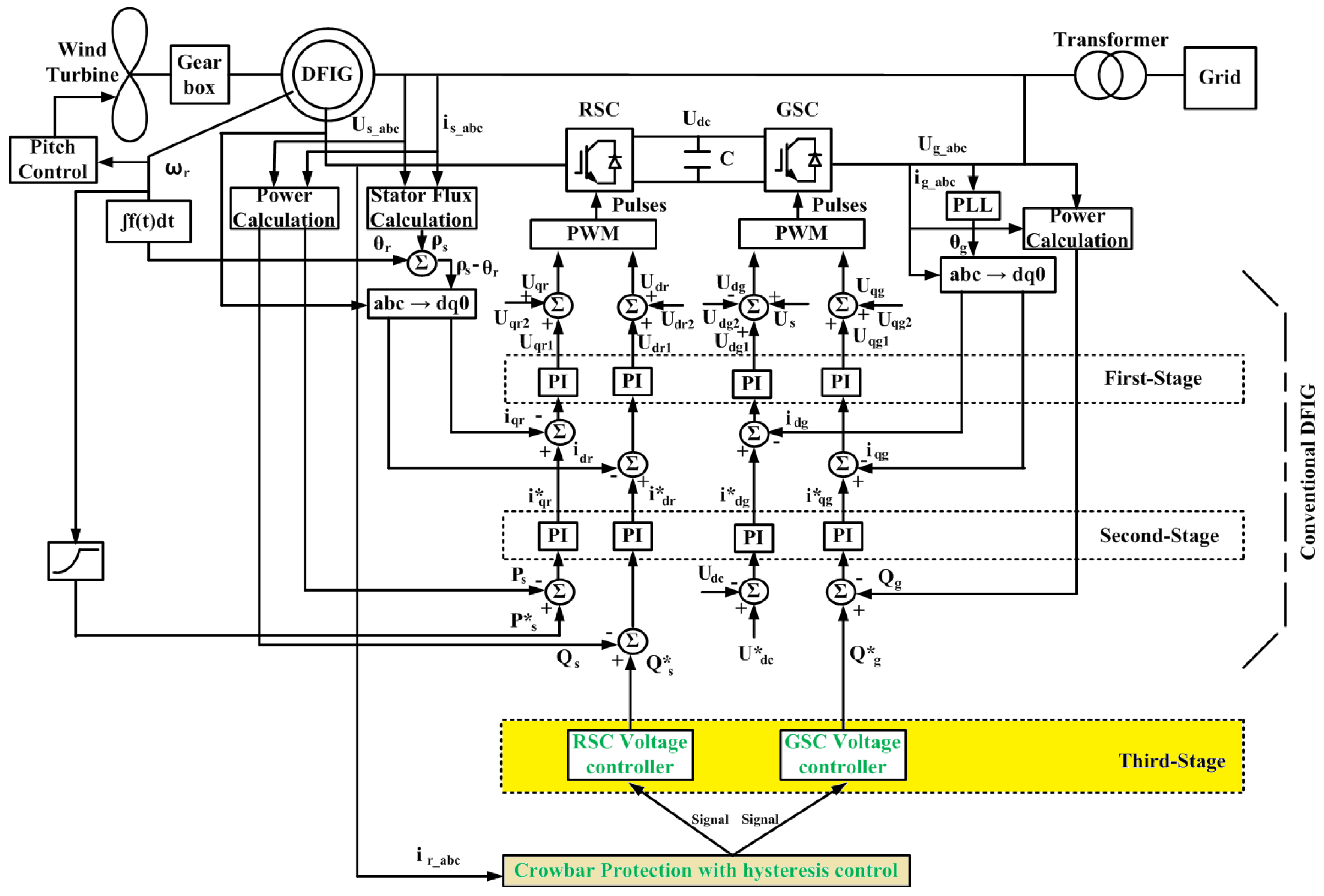
Figure 3 illustrates the scheme of DFIG connected to the mains, as well as the proposed controller structure with the monitored measures.
4.1. Conventional Scheme Using Crowbar Protection without Fault-Ride-Through
In this mode, RSC is independently controlling the active and reactive power on the grid. On the other hand, GSC aims to control the DC link voltage maintaining it at a defined value, regardless of the direction and magnitude of the rotor power, to keep the converter operating within the requirements [42].
In the second-stage controllers, the reference values are defined as follows:
- the reference value of active power, , is determined by the maximum power point tracking logic, depending on the optimal generator speed ;
- the reference value of RSC reactive power is in general set to zero;
- the reference value of GSC reactive power can be set to a particular value, or even to zero.
Thus, there is an active and reactive power exchange between the GSC and the upstream network, while the transmission of reactive power is zero through the stator, as reported in [43].
4.2. Proposed Scheme Using Crowbar Protection with Fault-Ride-Through
In case of mains supply short-circuits, the tasks of RSC and GSC may be changed depending on whether the crowbar protection is triggered or not [32]. If the crowbar is not triggered, the RSC and GSC realizes the objectives as in the conventional scheme [42]. Otherwise, in the first instants of the large short-circuit, the crowbar is triggered by over-currents in the rotor circuit, and the RSC is disabled and bypassed. Thus, the GSC supports the grid through reactive power.
After the short-circuit first instants, the GSC will continue its operation as a voltage controller, in order to deliver reactive power supporting voltage retention, as long as the RSC is blocked. After the current in the rotor circuit is decreasing under the threshold value, the crowbar circuit is removed, the RSC starts to operate as a voltage controller, in order to deliver reactive power supporting voltage retention, and the GSC is set again to be reactive neutral. Following the short-circuit clearance, the RSC supplied reactive power for supporting the voltage level, and active power to overcome power imbalances. When the voltage at the point of common coupling (PCC) recovers to a reference value, shortly after the fault, the DFIG power converter returns to normal operation.
The fault-ride-through control logic, shown in Figure 3 , reports the proposed coordinated control strategy of DFIG. The proposed scheme is based on crowbar protection and voltage control using both rotor side (RSC) and grid side converters (GSC). The definition of RSC and GSC voltage controller are shown in Figure 4 and Figure 5 respectively. These controllers produce and that must satisfy the reactive current requirements for German codes as shown in Figure 2 based on the difference between and at PCC. Since the difference voltage at PCC can vary by few percent for hundreds of microseconds, the implementation of a fuzzy logic controller can be useful [29] in addition to conventional controller to increase the sensitivity of error signals and . As reported in [43], the input control variables to the FLC are and and their derivatives. With any variation of and , the corresponding value of is computed. The variation of and is maintained in the same direction when and increase with last positive derivative. Otherwise, negative derivative causes a decrease in and , and the direction if search for a suitable and is immediately reversed [44]. In the following, all the variables are described by using a Fuzzy Logic language.
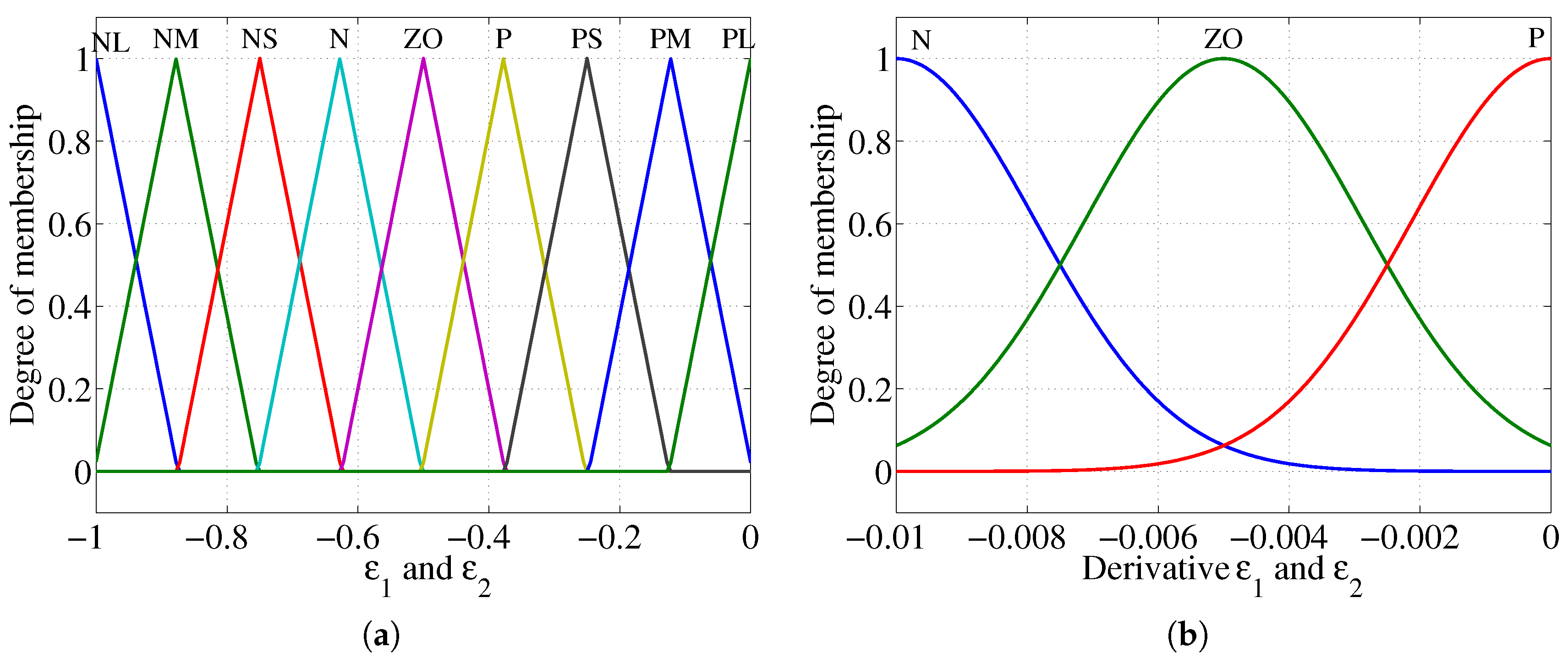
The usual fuzzy system structure has three basic blocks, which includes fuzzification (FI), decision-making logic (DML), defuzzification(DFI), and knowledge base (KB). The notations of , and voltage error derivative are taken from [7,44] and are characterized by the Triangular and Gaussian membership function, as shown in [28] and reported in Figure 6. While, for output and control, nine membership functions are chosen to be characterized by the triangular membership function according to [28], as reported in Figure 7.
The DML gives a fuzzy sets employing the rules based on the KB is reported in Table 1, then DFI is applied on the fuzzy sets produced by the DML in order to convert the fuzzy set into a numerical value by equation [45]:
where is the output reference pitch angle, is the weight corresponding to a given output fuzzy set, is the degree of the fuzzy rule, and x is the input vector.
With respect to the conventional fuzzy control shown in Figure 4 and Figure 5, the inputs and outputs of the advanced FLC are normalized by the coefficients = 5, = 3 × , = 1 × , = 3, = 3 × , and = 45 × , for computational convenience. These scaling factors can be constant or variable, and their role is critical in the FLC design to achieve a good response in both transient and steady state. In this research, for the simplicity of the controller design, the scaling factors are selected to be constant.
5. Results and Discussion
For correct operation of DFIG, the control of its converters is critical during both normal operation and fault conditions. The previous works [11,26,27] deal with the DFIG control performance during normal operating conditions. Nevertheless, the main attention of the present research is on the fault-ride through capability.
The proposed control system was implemented in MATLAB/Simulink on a 3 MW DFIG wind turbine. The DFIG supply network is illustrated in Figure 8, where the DFIG is connected, at the Point of common coupling (PCC), to 33 kV lines of 10 km length. The characteristic data of DFIG and network are reported in Table 2. The three-phase short-circuit to the ground is occurring at point F. The short-circuit occurs at time instant s and is cleared after 150 ms. The input wind speed profile is based on [7,27].
5.1. Crowbar with Hysteresis Controller Effect
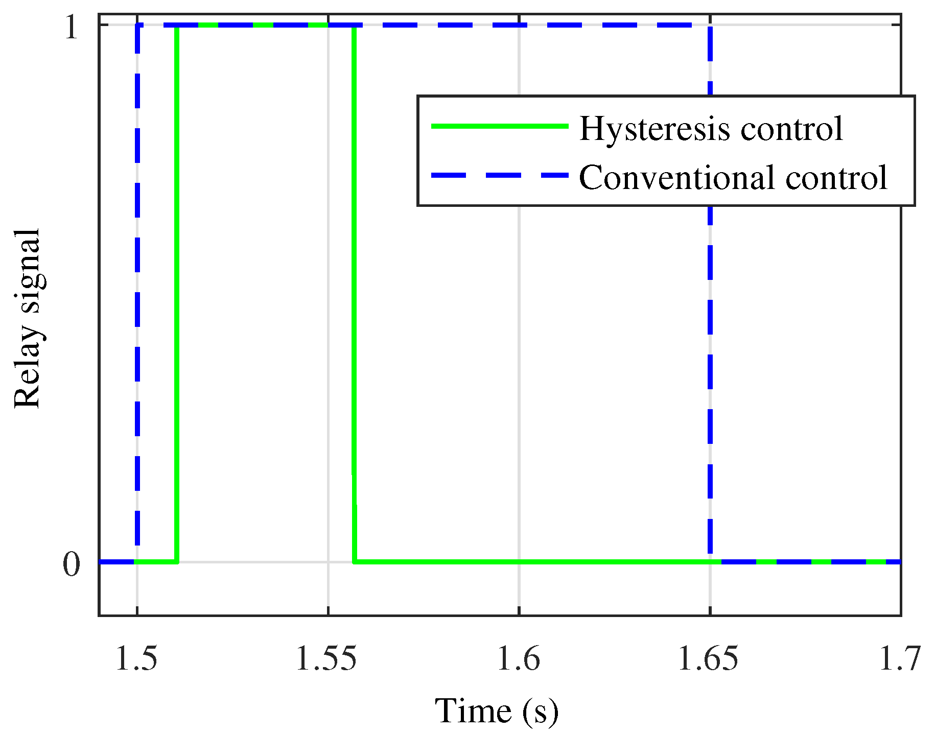
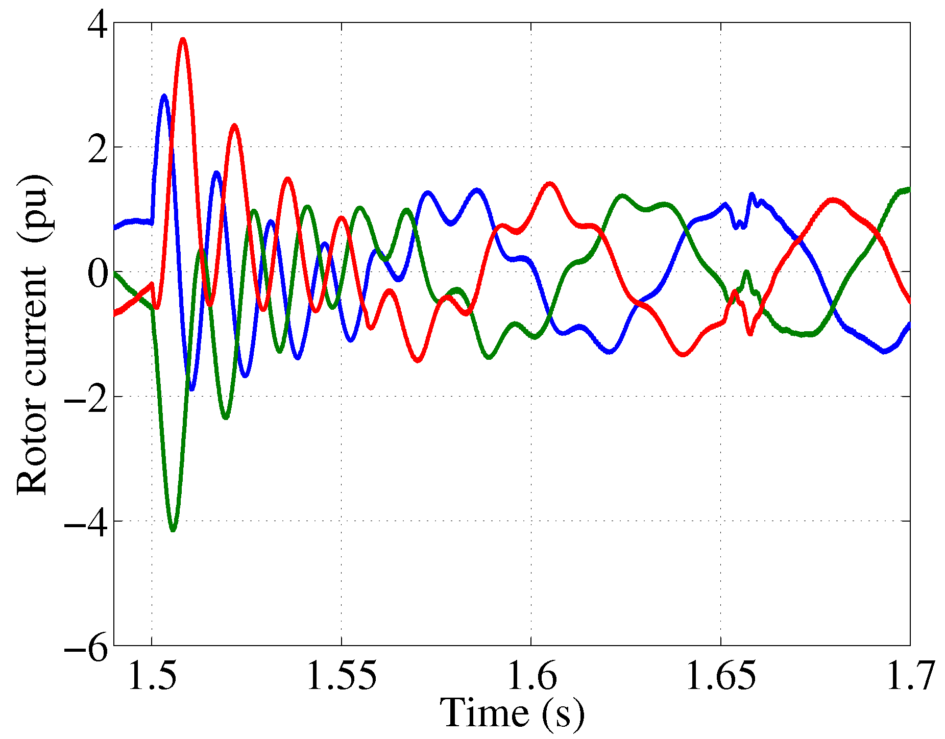
The crowbar effects on the transient response of DFIG have been already demonstrated in [39], both for conventional DFIG and for the LVRT control scheme, respectively. The hysteresis control proposed in [41] is here adopted as an improved LVRT control scheme, aimed to reduce the crowbar operation time. The simulation result of hysteresis output signal to switch on/off crowbar protection is shown in Figure 9. In contrast to the conventional control scheme, when the rotor current decrease continuously during the crowbar operation interval (from s to s), in the proposed control scheme the crowbar is activated with a delay of about 20 ms (due to hysteresis) and the rotor current returns to its normal operation condition after about 40 ms s [39], as reported in Figure 10.
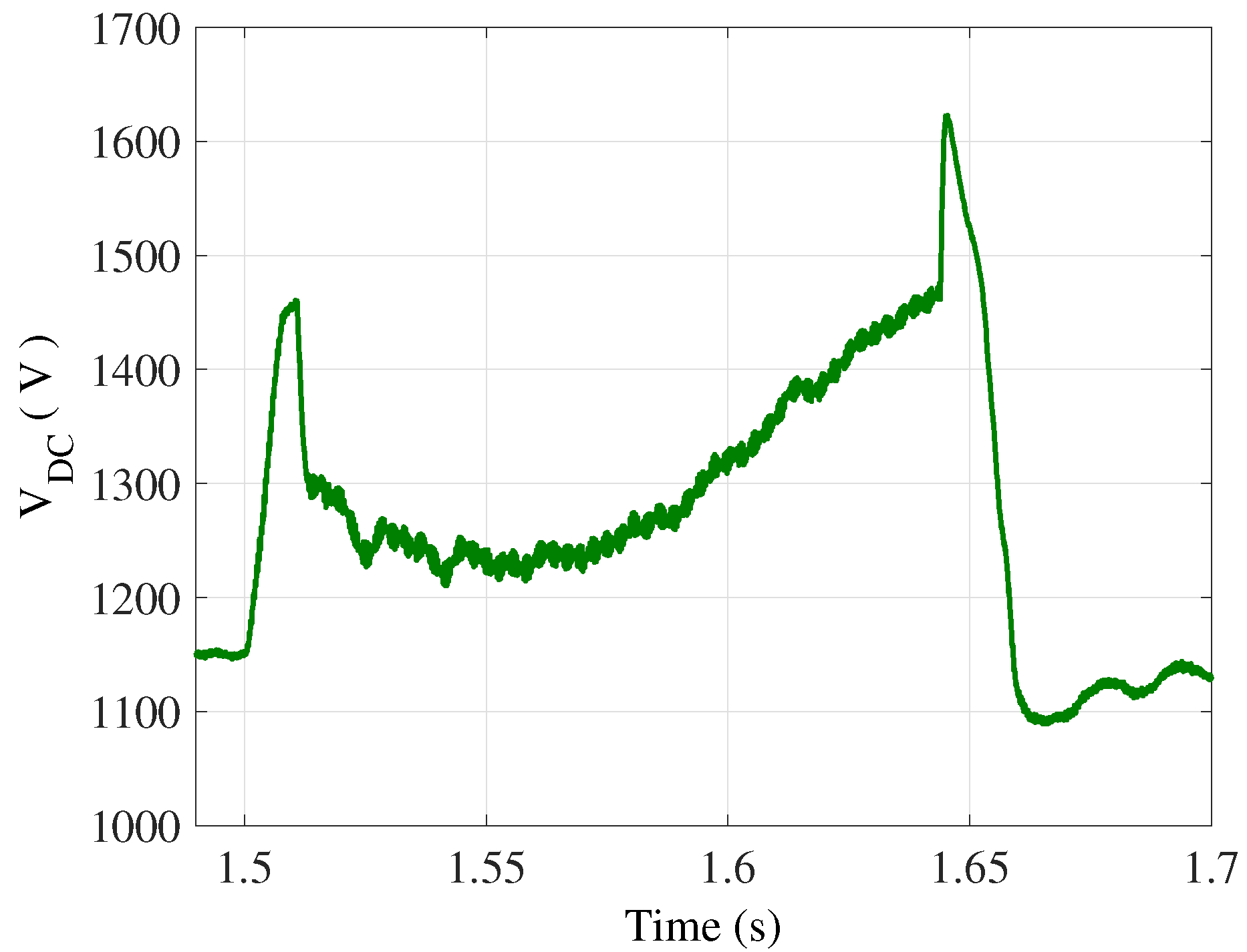
Similarly, the dc-voltage of capacitor starts discharging when the crowbar is triggered; the dc-link voltage returns back to charging, when the RSC starts actively to control the reactive power. After fault clearance, the GSC begins to control the dc-link voltage back to its reference (Figure 11). It is clear that a crowbar with hysteresis control has a faster operation time, meaning that the DFIG with the proposed FRT scheme is more controllable during the voltage dip condition.
5.2. Performance Assessment of Voltage Grid Support Capability
The performance of the proposed controller for coordinating RSC and GSC for ensuring voltage support were investigated under transient phenomena occurring in the analyzed DFIG supply system. Figure 12 illustrates the variation of PCC voltage for the cases of DFIG with/without fault-ride-through capability.
The transient-state performance is analyzed here in terms of voltage control capability of the proposed coordinated controller. Figure 12 compares the behavior of the PCC voltage with and without the LVRT control scheme. The PCC voltage with LVRT control scheme is above Germany grid codes, in regaining its pre-fault value, while the conventional DFIG with crowbar protection without LVRT fails.
The variation of voltage at generator terminals (Figure 13) with high amount of reactive power should be noted. This is generated by the coordinated control between voltage support of GSC (when the rotor current exceeds the admitted value) and RSC (when the rotor current decreases to secure region), in order to boost the PCC voltage at fault clearance (Figure 12).
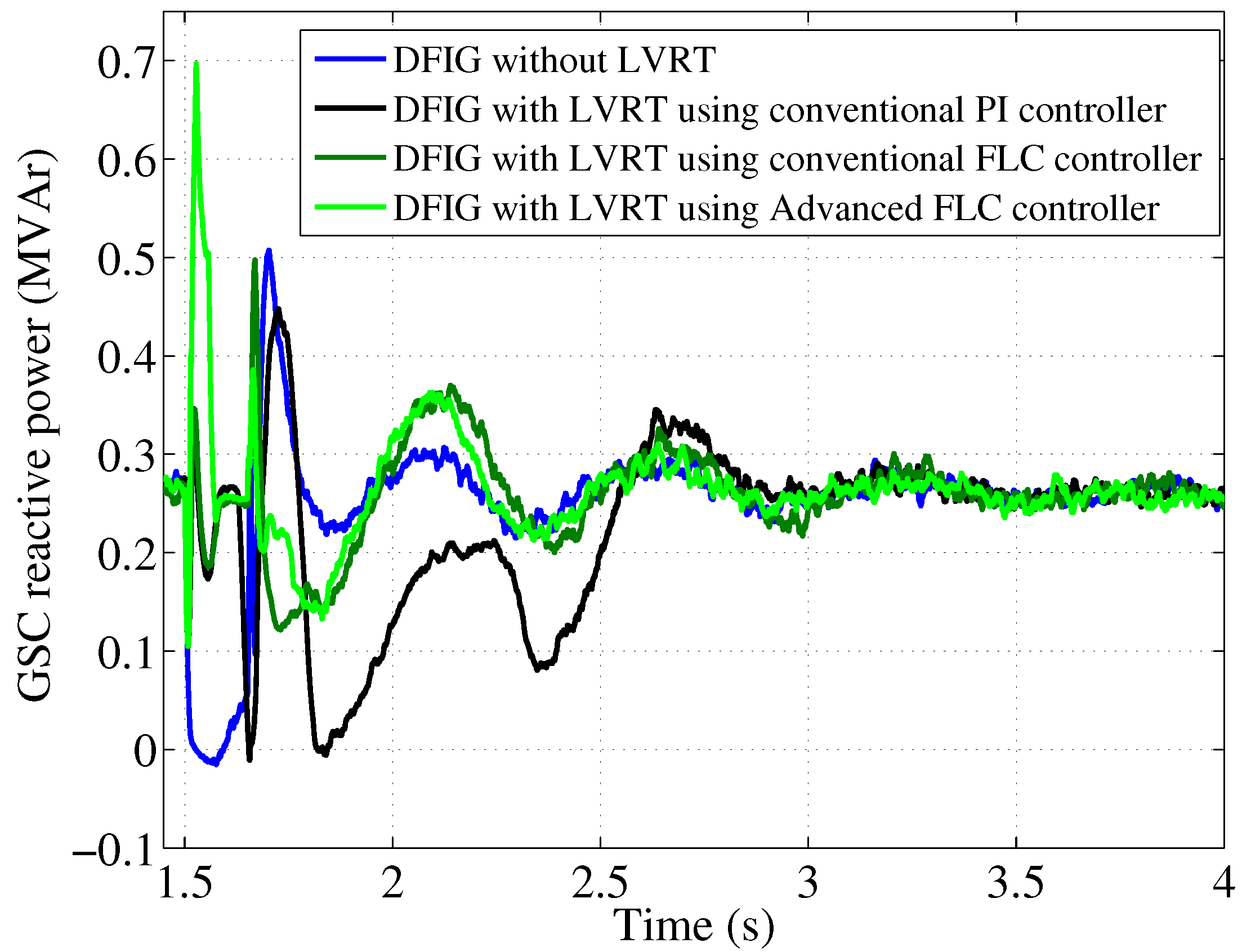
Moreover, for comparison, the LVRT control scheme has been simulated with three different control techniques considering PCC voltage dips. These strategies are: conventional proportional-integral (PI) controller, conventional fuzzy logic controller (FLC), and advanced fuzzy logic controller (Advanced FLC).
Figure 14 shows the total additional reactive power generated for voltage support, shared between GSC (Figure 15) and RSC (Figure 16) with the proposed scheme controller. The reactive power generated by DFIG without fault-ride-through capability decreases to zero. In the meanwhile, the reactive power generated by the voltage control logic of GSC and RSC has an opposite variation compared to the conventional scheme of RSC and GSC, as the DFIG with fault-ride-through control logic is used to maintain the voltage at PCC.
Furthermore, during the initial period of a large fault, the task to support the grid with reactive power is taken over by the GSC. As a result, Figure 15 shows the generator reactive power which is not well maintain at the rated value and has high ripple components with the PI/FLC controllers, whereas it is kept almost at the rated value by the Advanced FLC strategy. Regarding the generator reactive power of RSC, whose task is to support the grid when the current in the rotor circuit is reduced below the threshold value, a similar performance is shown in Figure 16. For the sake of completeness, the variation of output active power is shown in Figure 17.
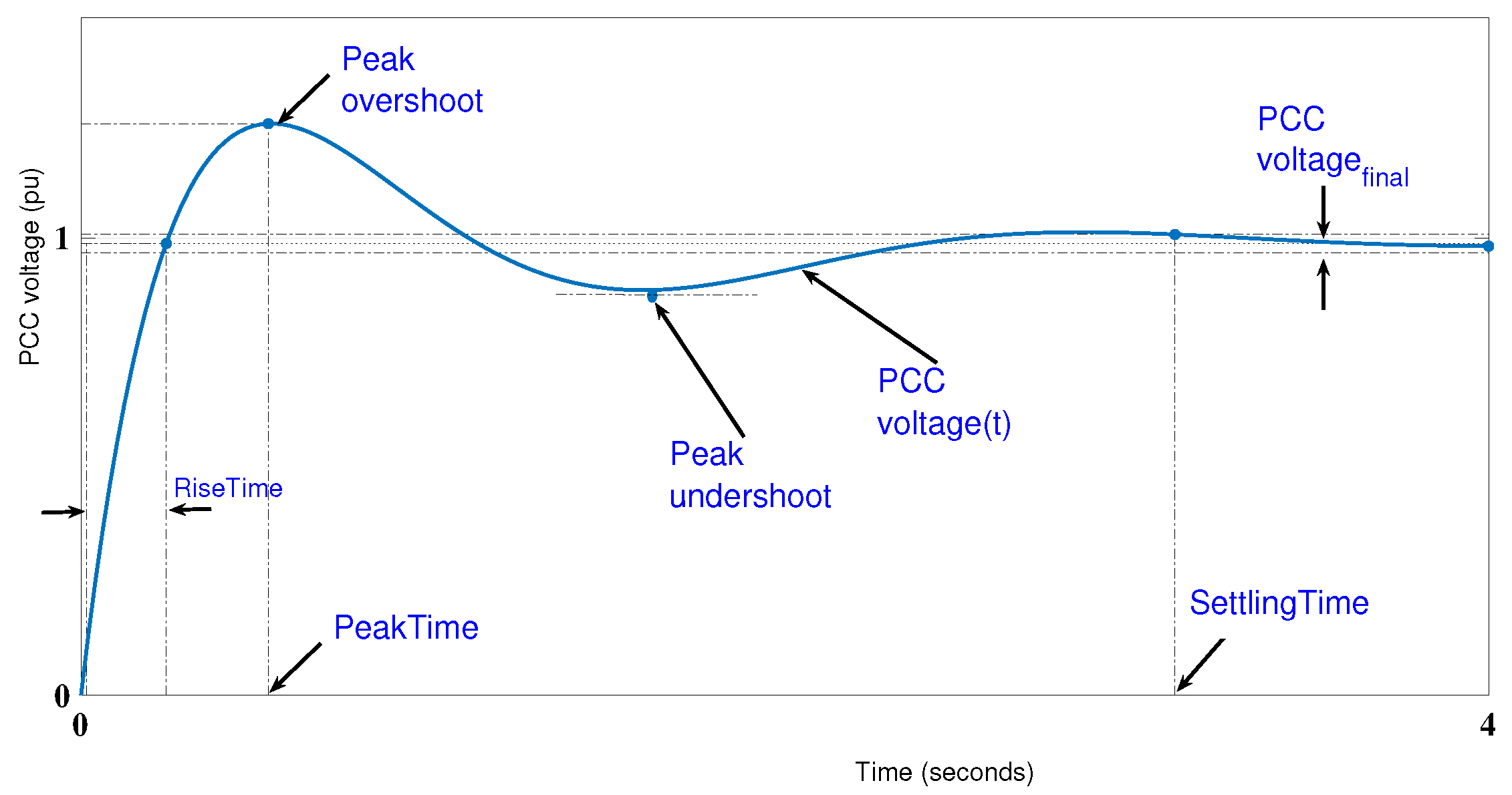
Moreover, these three control strategies lead to more obvious differences in reactive power curves. With the advanced FLC controller, over 0.5 pu of reactive power is delivered to the grid during the fault from GSC (Figure 15). The strategy with conventional PI and FLC is lower than 0.3 pu, under this scenario. As a result, the strategy with advanced FLC controller introduces relatively high terminal voltage when the RSC is disconnected from the rotor circuit, compared with the other two strategies (Figure 13). Behaving like DFIG without LVRT, strategies with conventional PI as well as fuzzy controller absorb reactive power from the grid after fault is eliminated in Figure 14. On the other hand, the strategy with advanced FLC provides reactive power to grid continuously. In Figure 16, showing the RSC reactive power of DFIG, all strategies meet the requirement with reasonably high reactive power during the fault condition. Moreover, compared with the results in Figure 12, Figure 13 and Figure 14, the performance of the advanced FLC strategy is more effective and smooth in providing reactive power and recovering voltage. To demonstrate the effectiveness of three control strategies, we have reported in Table 3 a number of performance indexes computed from Figure 12. The meaning of these indicator is clarified in Figure 18: in particular, settling time () is the time for the response to rise from 0 to the steady-state value ; rise time () is the time for the response to rise from 10% to 100% of the steady-state response; peak overshoot (), i.e., the percentage overshoot relative to , and peak undershoot (), i.e., the percentage undershoot relative to , are defined as follows:
where is the peak overshoot response of PCC voltage, is the peak undershoot response of PCC voltage, is the steady-state value of the PCC voltage.
As a result, the coordination between RSC and GSC in the third-stage of FRT and damping control appears to be effective, by suitably achieving the desired results in terms of improved voltage grid support during the fault condition and post-fault.
6. Conclusions
This paper presented an efficient control logic for voltage grid support in case of power systems supplying DFIG under short-circuit occurrences in the supply system. The fault-ride-through capability was improved by using the good control capability of the DFIG wind system, as well as proposed fuzzy logic technique.
The main contribution of this paper is the coordinated control between GSC and RSC, controlling and sustaining the voltage level in a coordination mode. Usually, the reactive power control is the responsibility of the RSC controller. During the period when the crowbar protection is on, the voltage support is realized by the GSC control logic. The proposed control system effectively regulates reactive power output of the DFIG wind turbine to compensate the reactive power absorbed by this machine during large disturbances.
The effectiveness of control technique based on PI, FLC and advanced FLC are compared. The advanced FLC controller, a new simple control strategy based on computational intelligence, appears to be more effective than the existing methods, including the active crowbar protection both in performance and in the improvement of grid reliability.
The simulation results confirm that the proposed coordinated control strategy is successful in providing the supplementary reactive power from the RSC and GSC thus improves the DFIG fault-ride-through capability.
Acknowledgments
This research is funded by Funds for Science and Technology Development of the University of Danang under project B2017-DN02-31.
Author Contributions
In this research activity, all of the authors were involved in the data analysis and preprocessing phase, the simulation, the results analysis and discussion, and the manuscript’s preparation. All of the authors have approved the submitted manuscript. All the authors equally contributed to the writing of the paper.
Conflicts of Interest
The authors declare no conflict of interest.
References
- Global Wind Energy Council (GWEC). Global Wind Report—Annual Market Update; Global Wind Energy Council (GWEC): Brussels, Belgium, 2014. [Google Scholar]
- Golovanov, N.; Lazaroiu, G.; Roscia, M.; Zaninelli, D. Power Quality analysis in Renewable Energy Systems Supplying Distribution Grids. Measurements 2013, 7, 6–95. [Google Scholar] [CrossRef]
- Grimaccia, F.; Mussetta, M.; Zich, R. Neuro-fuzzy predictive model for PV energy production based on weather forecast. In Proceedings of the 2011 IEEE International Conference on Fuzzy Systems (FUZZ), Taipei, Taiwan, 27–30 June 2011; pp. 2454–2457. [Google Scholar]
- Shen, C.; Kaufmann, P.; Braun, M. Optimizing the generator start-up sequence after a power system blackout. In Proceedings of the 2014 IEEE PES General Meeting|Conference & Exposition, National Harbor, MD, USA, 27–31 July 2014; pp. 1–5. [Google Scholar]
- Duong, M.Q.; Ogliari, E.; Grimaccia, F.; Leva, S.; Mussetta, M. Hybrid model for hourly forecast of photovoltaic and wind power. In Proceedings of the 2013 IEEE International Conference on Fuzzy Systems (FUZZ), Hyderabad, India, 7–10 July 2013; pp. 1–6. [Google Scholar]
- Caputo, D.; Grimaccia, F.; Mussetta, M.; Zich, R. Photovoltaic plants predictive model by means of ANN trained by a hybrid evolutionary algorithm. In Proceedings of the 2010 International Joint Conference on Neural Networks (IJCNN), Barcelona, Spain, 18–23 July 2010; pp. 1–6. [Google Scholar]
- Duong, M.Q.; Grimaccia, F.; Leva, S.; Mussetta, M.; Ogliari, E. Pitch Angle Control Using Hybrid Controller for all Operating Regions of SCIG Wind Turbine System. Renew. Energy 2014, 70, 197–203. [Google Scholar] [CrossRef]
- Jafari, S.H.; Raoofat, M.; Samet, H. Improving transient stability of double fed induction generator using fuzzy controller. Int. Trans. Electr. Energy Syst. 2014, 24, 1065–1075. [Google Scholar] [CrossRef]
- Jazaeri, M.; Samadi, A.A. Self-tuning fuzzy PI-based controller of DFIG wind turbine for transient conditions enhancement. Int. Trans. Electr. Energy Syst. 2014, 25, 2657–2673. [Google Scholar] [CrossRef]
- Tsili, M.; Papathanassiou, S. A review of grid code technical requirements for wind farms. IET Renew. Power Gener. 2009, 3, 308–332. [Google Scholar] [CrossRef]
- Duong, M.Q.; Le, K.H.; Grimaccia, F.; Leva, S.; Mussetta, M.; Zich, R. Comparison of power quality in different grid-integrated wind turbines. In Proceedings of the 2014 16th International Conference on Harmonics and Quality of Power (ICHQP), Bucharest, Romania, 25–28 May 2014; pp. 448–452. [Google Scholar]
- Muller, S.; Deicke, M.; De Doncker, R.W. Doubly fed induction generator systems for wind turbines. IEEE Ind. Appl. Mag. 2002, 8, 26–33. [Google Scholar] [CrossRef]
- Cárdenas, R.; Peña, R.; Alepuz, S.; Asher, G. Overview of control systems for the operation of DFIGs in wind energy applications. IEEE Trans. Ind. Electron. 2013, 7, 2776–2798. [Google Scholar] [CrossRef]
- Sava, G.N.; Costinas, S.; Golovanov, N.; Leva, S.; Duong, M.Q. Comparison of active crowbar protection schemes for DFIGs wind turbines. In Proceedings of the 2014 16th International Conference on Harmonics and Quality of Power (ICHQP), Bucharest, Romania, 25–28 May 2014; pp. 669–673. [Google Scholar]
- Kasem, A.H.; El-Saadany, E.F.; El-Tamaly, H.; Wahab, M. An improved fault ride-through strategy for doubly fed induction generator-based wind turbines. IET Renew. Power Gener. 2008, 2, 201–214. [Google Scholar] [CrossRef]
- López, J.; Gubía, E.; Olea, E.; Ruiz, J.; Marroyo, L. Ride through of wind turbines with doubly fed induction generator under symmetrical voltage dips. IEEE Trans. Ind. Electron. 2009, 56, 4246–4254. [Google Scholar] [CrossRef]
- Kayikçi, M.; Milanović, J. Assessing transient response of DFIG-based wind plants—The influence of model simplifications and parameters. IEEE Trans. Power Syst. 2008, 23, 545–554. [Google Scholar] [CrossRef]
- Yang, J.; Fletcher, J.E.; O’Reilly, J. A series-dynamic-resistor-based converter protection scheme for doubly-fed induction generator during various fault conditions. IEEE Trans. Energy Convers. 2010, 25, 422–432. [Google Scholar] [CrossRef]
- Hansen, A.D.; Michalke, G. Fault ride-through capability of DFIG wind turbines. Renew. Energy 2007, 32, 1594–1610. [Google Scholar] [CrossRef]
- Hansen, A.D.; Michalke, G. Voltage grid support of DFIG wind turbines during grid faults. In Proceedings of the 2007 European Wind Energy Conference and Exhibition, Milan, Italy, 7–10 May 2007; pp. 93–97. [Google Scholar]
- Slootweg, J.; Kling, W. The impact of large scale wind power generation on power system oscillations. Electr. Power Syst. Res. 2003, 67, 9–20. [Google Scholar] [CrossRef]
- Gautam, D.; Vittal, V.; Harbour, T. Impact of increased penetration of DFIG-based wind turbine generators on transient and small signal stability of power systems. IEEE Trans. Power Syst. 2009, 24, 1426–1434. [Google Scholar] [CrossRef]
- Xiang, D.; Ran, L.; Tavner, P.J.; Yang, S. Control of a doubly fed induction generator in a wind turbine during grid fault ride-through. IEEE Trans. Energy Convers. 2006, 21, 652–662. [Google Scholar] [CrossRef]
- Abad, G.; Rodriguez, M.; Poza, J.; Canales, J. Direct torque control for doubly fed induction machine-based wind turbines under voltage dips and without crowbar protection. IEEE Trans. Energy Convers. 2010, 25, 586–588. [Google Scholar] [CrossRef]
- Yu, L.; Chen, G.C.; Cao, D.P.; Wu, G.X. Low voltage ride-through control of doubly fed induction generator during symmetric voltage sag. Electr. Mach. Control 2010, 14, 1–6. [Google Scholar]
- Pena, R.; Clare, J.; Asher, G. Doubly fed induction generator using back-to-back PWM converters and its application to variable-speed wind-energy generation. IEE Proc. Electr. Power Appl. 1996, 143, 231–241. [Google Scholar] [CrossRef]
- Duong, M.Q.; Grimaccia, F.; Leva, S.; Mussetta, M.; Sava, G.; Costinas, S. Performance analysis of grid-connected wind turbines. UPB Sci. Bull. C Electr. Eng. 2014, 76, 169–180. [Google Scholar]
- Duong, M.Q.; Grimaccia, F.; Leva, S.; Mussetta, M.; Le, K.H. A hybrid Fuzzy-PI cascade controller for transient stability improvement in DFIG wind generators. In Proceedings of the 2016 IEEE International Conference on Fuzzy Systems (FUZZ-IEEE), Vancouver, BC, Canada, 24–29 July 2016; pp. 1733–1739. [Google Scholar]
- Van, T.; Nguyen, T.; Lee, D. Advanced Pitch Angle Control Based on Fuzzy Logic for Variable-Speed Wind Turbine Systems. IEEE Trans. Energy Convers. 2015, PP, 1–10. [Google Scholar] [CrossRef]
- Boverie, S.; Demaya, B.; Ketata, R.; Titli, A. Performance evaluation of fuzzy controllers. IFAC Proc. Vol. 1992, 25, 69–74. [Google Scholar] [CrossRef]
- Godjevac, J. Comparison between PID and Fuzzy Control; Internal Report 93; Ecole Polytechnique Federale de Lausanne, Departement d’Informatique, Laboratoire de Microinformatique: Lausanne, Switzerland, 1993. [Google Scholar]
- Fortmann, J.; Pfeiffer, R.; Haesen, E.; van Hulle, F.; Martin, F.; Urdal, H.; Wachtel, S. Fault-ride-through requirements for wind power plants in the ENTSO-E network code on requirements for generators. IET Renew. Power Gener. 2014, 9, 18–24. [Google Scholar] [CrossRef]
- Netz, E. Grid Code High and Extra High Voltage; E. ON Netz GmbH: Bayreuth, Germany, 2006. [Google Scholar]
- ENTSO-E AISBL. ENTSO-E Network Code for Requirements for Grid Connection Applicable to All Generators; ENTSO-E AISBL: Brussels, Belgium, 2012. [Google Scholar]
- Schlabbach, J. Low voltage fault ride through criteria for grid connection of wind turbine generators. In Proceedings of the 2008 5th International Conference on European Electricity Market (EEM), Lisboa, Portugal, 28–30 May 2008; pp. 1–4. [Google Scholar]
- Peña, R.; Cárdenas, R.; Reyes, E.; Clare, J.; Wheeler, P. Control of a doubly fed induction generator via an indirect matrix converter with changing DC voltage. IEEE Trans. Ind. Electron. 2011, 58, 4664–4674. [Google Scholar] [CrossRef]
- Lopez, J.; Sanchis, P.; Roboam, X.; Marroyo, L. Dynamic behavior of the doubly fed induction generator during three-phase voltage dips. IEEE Trans. Energy Convers. 2007, 22, 709. [Google Scholar] [CrossRef]
- Abdel-Baqi, O.; Nasiri, A. Series voltage compensation for DFIG wind turbine low-voltage ride-through solution. IEEE Trans. Energy Convers. 2011, 26, 272–280. [Google Scholar] [CrossRef]
- Duong, M.Q.; Nguyen, H.H.; Le, K.H.; Phan, T.V.; Mussetta, M. Simulation and performance analysis of a new LVRT and damping control scheme for DFIG wind turbines. In Proceedings of the 2016 IEEE International Conference on Sustainable Energy Technologies (ICSET), Hanoi, Vietnam, 14–16 November 2016; pp. 288–293. [Google Scholar]
- Abad, G.; Lopez, J.; Rodríguez, M.; Marroyo, L.; Iwanski, G. Doubly Fed Induction Machine: Modeling and Control for Wind Energy Generation; John Wiley & Sons: New York, NY, USA, 2011; Volume 86. [Google Scholar]
- Peng, L.; Francois, B.; Li, Y. Improved crowbar control strategy of DFIG based wind turbines for grid fault ride-through. In Proceedings of the Twenty-Fourth Annual IEEE Applied Power Electronics Conference and Exposition (APEC), Washington, DC, USA, 15–19 February 2009; pp. 1932–1938. [Google Scholar]
- Qiao, W.; Harley, R.G.; Venayagamoorthy, G.K. Coordinated reactive power control of a large wind farm and a STATCOM using heuristic dynamic programming. IEEE Trans. Energy Convers. 2009, 24, 493–503. [Google Scholar] [CrossRef]
- Duong, M.Q.; Grimaccia, F.; Leva, S.; Mussetta, M.; Zich, R. Improving LVRT characteristics in variable-speed wind power generation by means of fuzzy logic. In Proceedings of the 2014 IEEE International Conference on Fuzzy Systems (FUZZ-IEEE), Beijing, China, 6–11 July 2014; pp. 332–337. [Google Scholar]
- Duong, M.Q.; Grimaccia, F.; Leva, S.; Mussetta, M.; Le, K.H. Improving Transient Stability in a Grid-Connected Squirrel-Cage Induction Generator Wind Turbine System Using a Fuzzy Logic Controller. Energies 2015, 8, 6328. [Google Scholar] [CrossRef] [Green Version]
- Abe, S. Fuzzy function approximators with ellipsoidal regions. IEEE Trans. Syst. Man Cybern. B Cybern. 1999, 29, 654–661. [Google Scholar] [CrossRef] [PubMed]
Figure 1.
Low-Voltage Ride Through (LVRT) requirements of several grid codes.
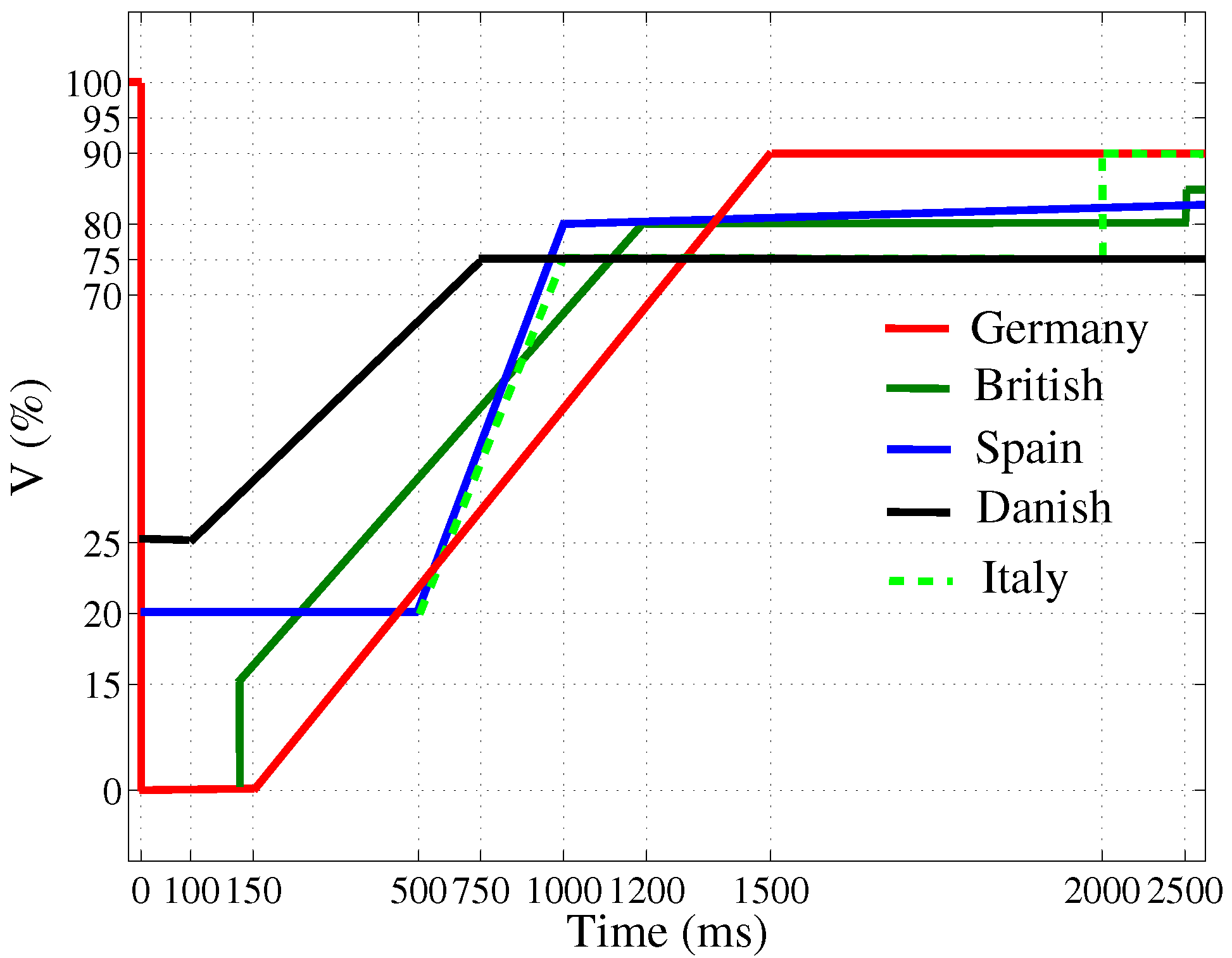
Figure 2.
Reactive current requirements for German codes [33].
Figure 2.
Reactive current requirements for German codes [33].
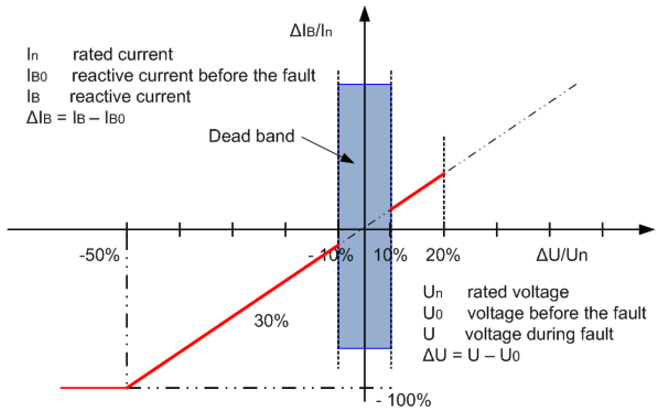
Figure 3.
Crowbar Protection and LVRT control scheme of doubly-fed induction generator (DFIG). RSC: rotor side converter; GSC: grid side converter; PWM: Pulse-width modulation; PLL: Phase-locked loop; PI: Proportional Integral.
Figure 3.
Crowbar Protection and LVRT control scheme of doubly-fed induction generator (DFIG). RSC: rotor side converter; GSC: grid side converter; PWM: Pulse-width modulation; PLL: Phase-locked loop; PI: Proportional Integral.

Figure 4.
Block diagram of the LVRT for rotor side converter (RSC) voltage controller. FLC: Fuzzy Logic Controller.
Figure 4.
Block diagram of the LVRT for rotor side converter (RSC) voltage controller. FLC: Fuzzy Logic Controller.
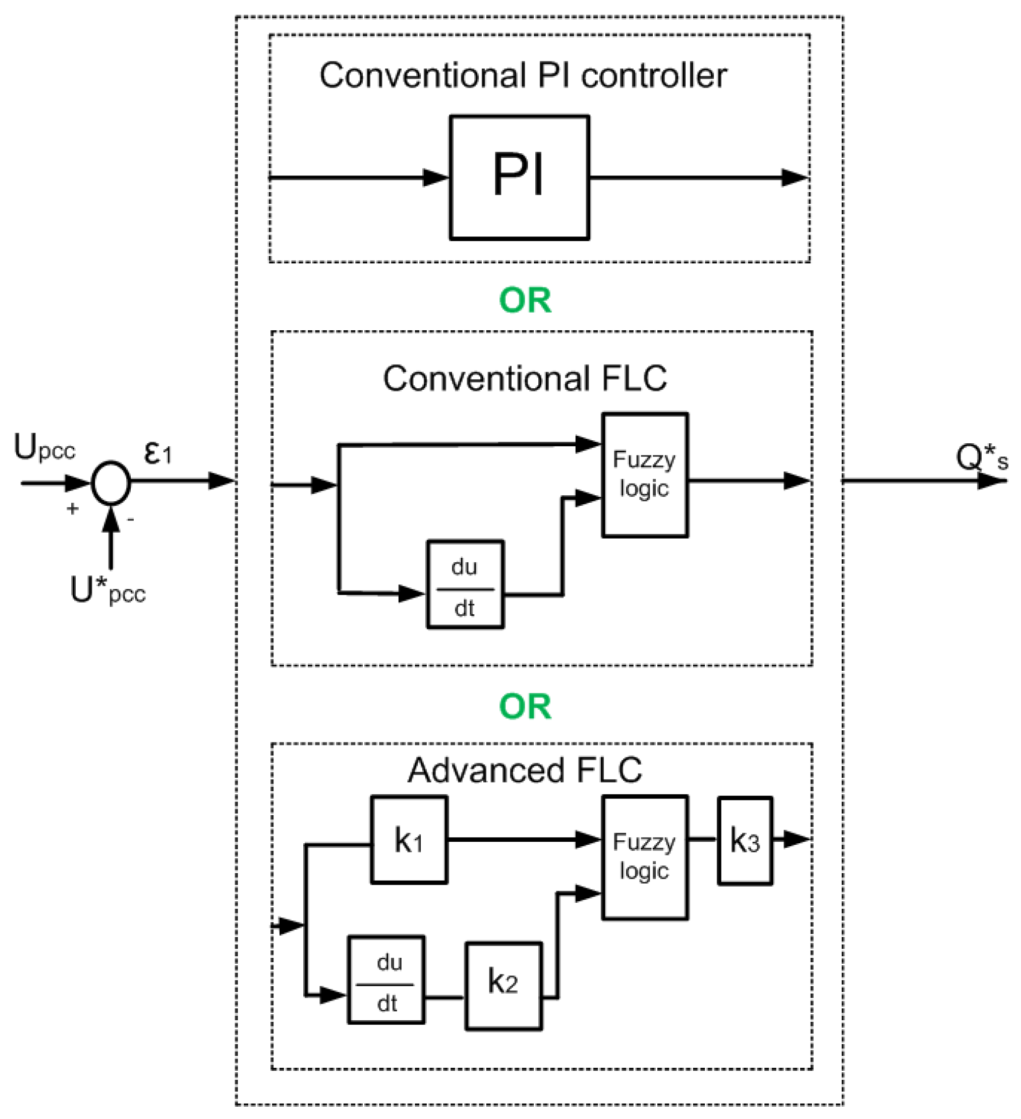
Figure 5.
Block diagram of the LVRT for grid side converter (GSC) voltage controller.
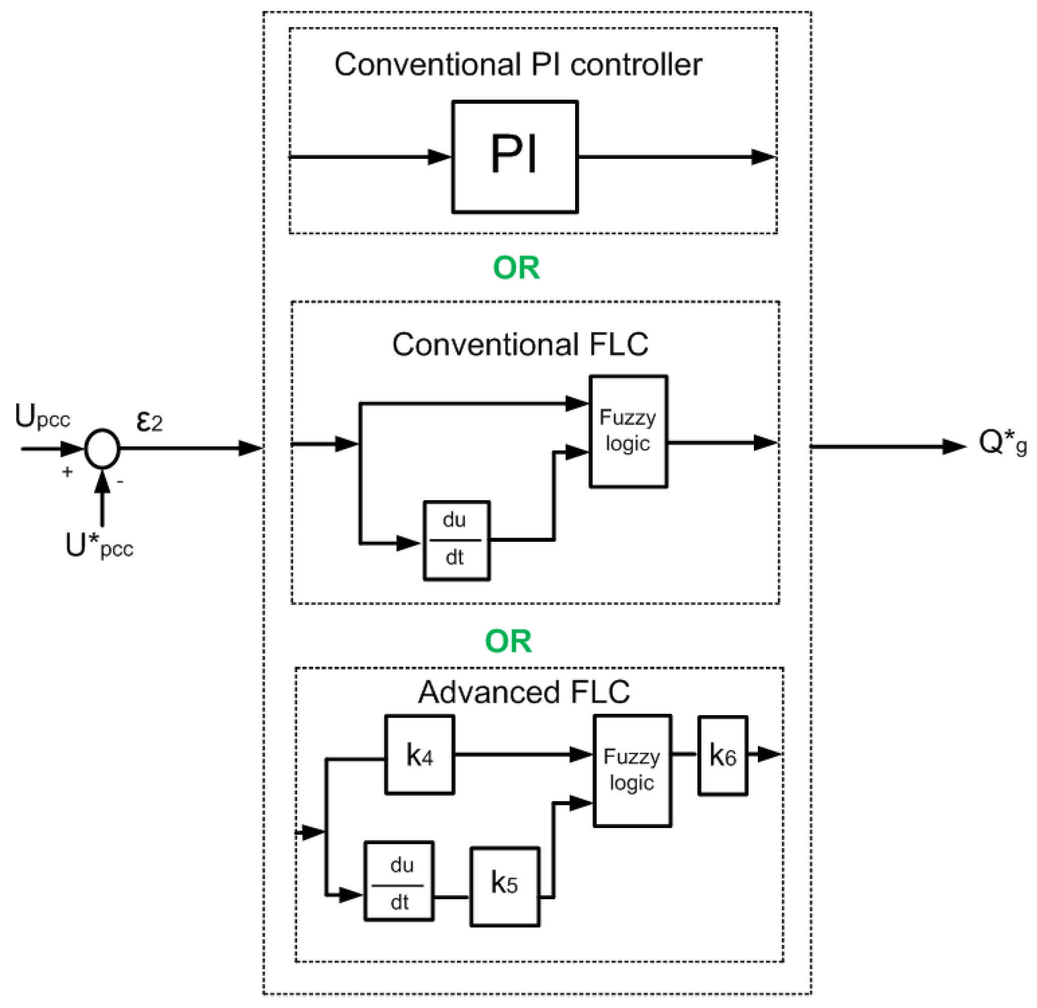
Figure 6.
Input fuzzy set for voltage error (a) and its derivative (b).

Figure 7.
Output fuzzy set for reactive power control from RSC (a) and GSC (b).
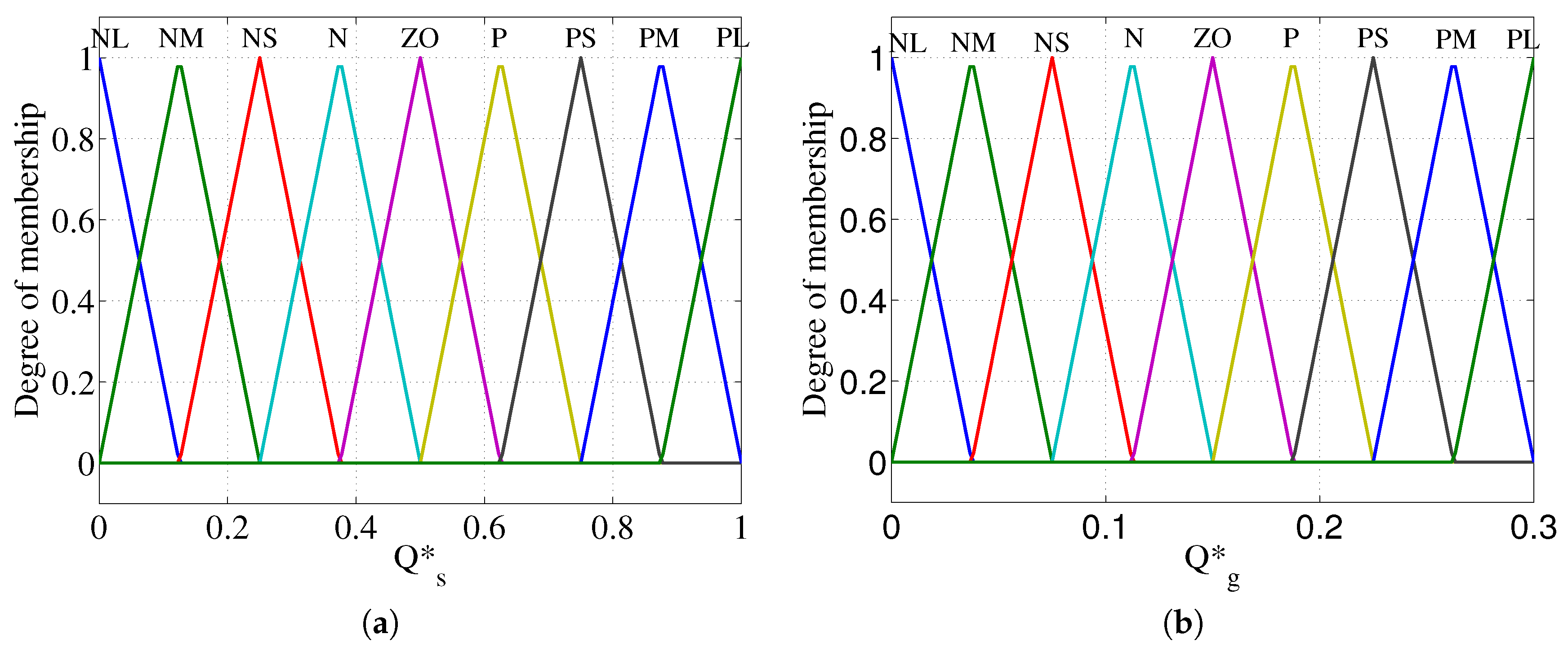
Figure 8.
Coupled Doubly-Fed Induction Generator (DFIG) based wind power plant (WPP) with Point of common coupling (PCC).
Figure 8.
Coupled Doubly-Fed Induction Generator (DFIG) based wind power plant (WPP) with Point of common coupling (PCC).
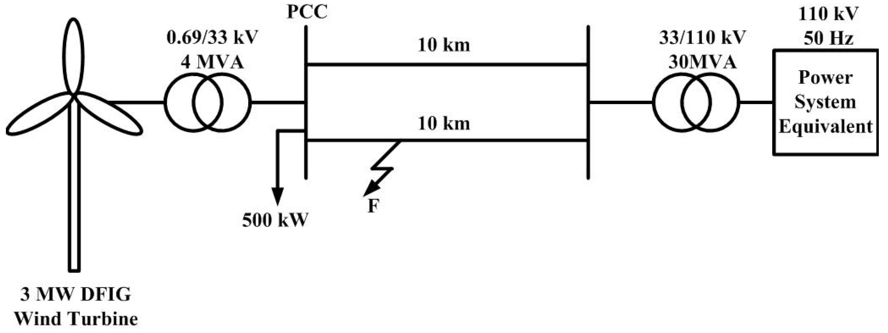
Figure 9.
Hysteresis control signal for the crowbar, compared with the conventional control scheme.

Figure 10.
Rotor current of Doubly-Fed Induction Generator (DFIG) with LVRT scheme.

Figure 11.
DC voltage of DFIG with LVRT scheme.

Figure 12.
The voltage at the point of common coupling (PCC).
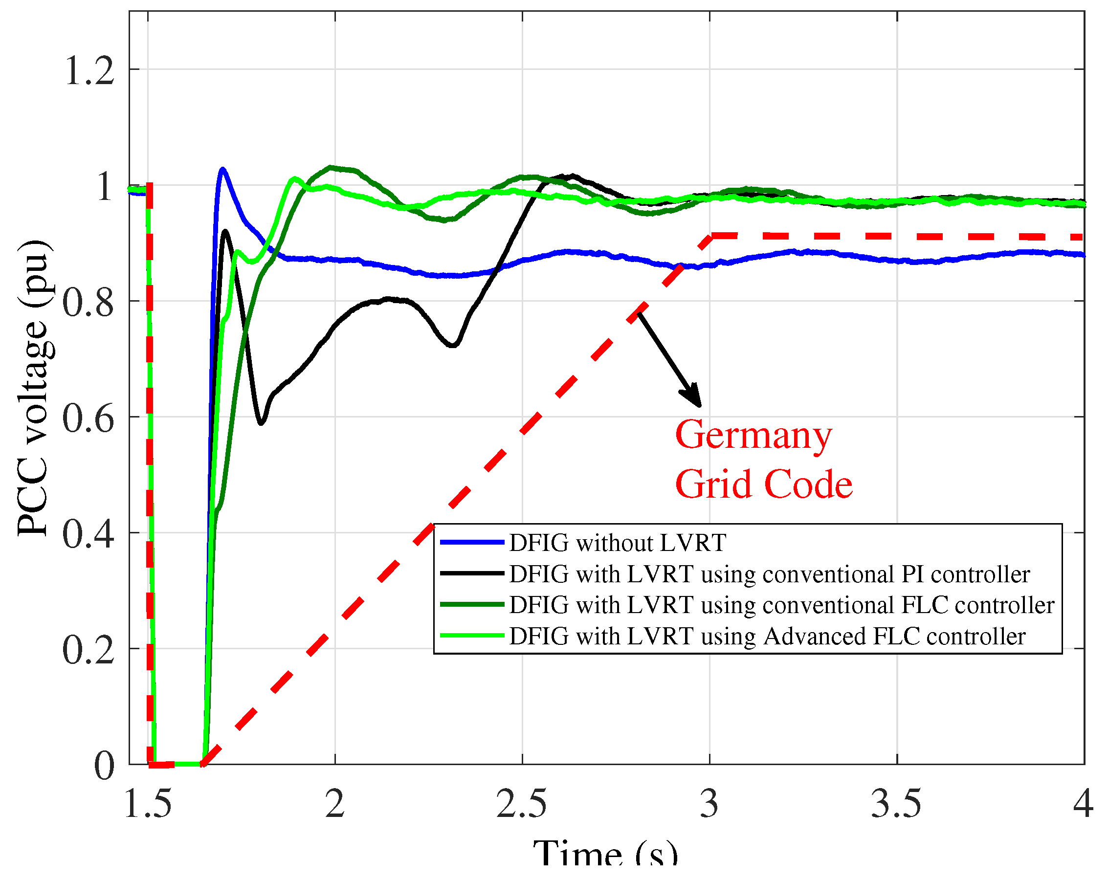
Figure 13.
The voltage U at DFIG-based wind power plant terminal.
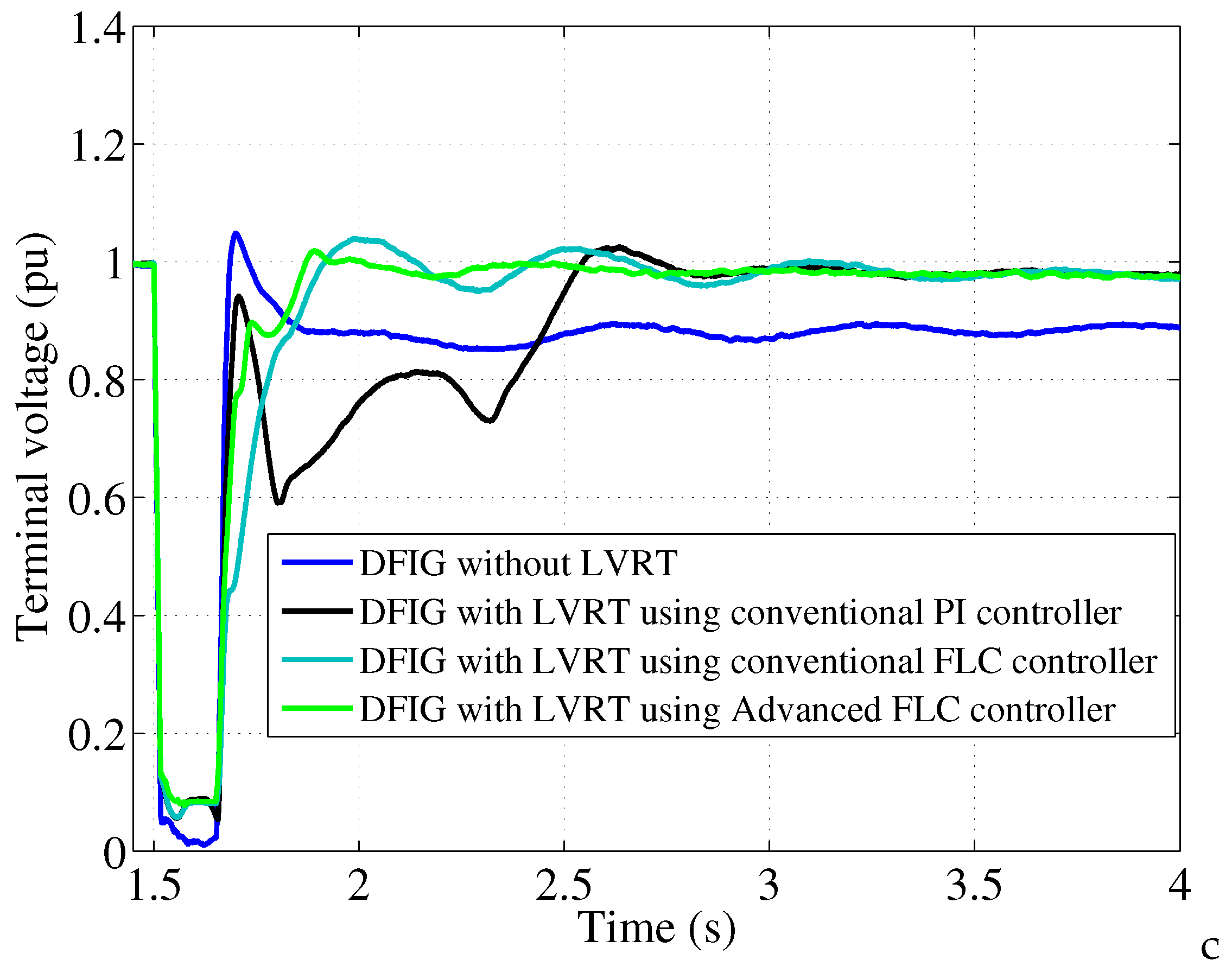
Figure 14.
The DFIG reactive power output.
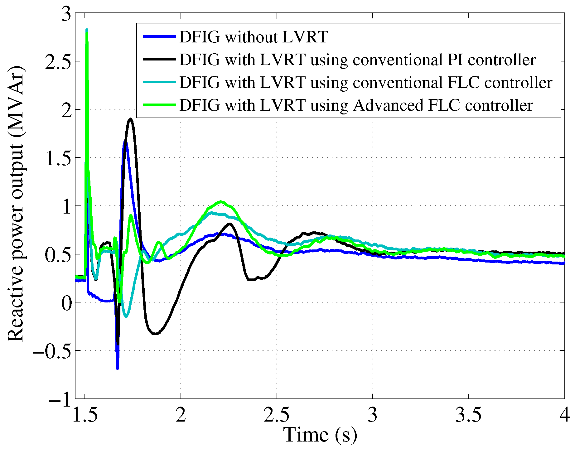
Figure 15.
The GSC reactive power output.

Figure 16.
The RSC reactive power output.
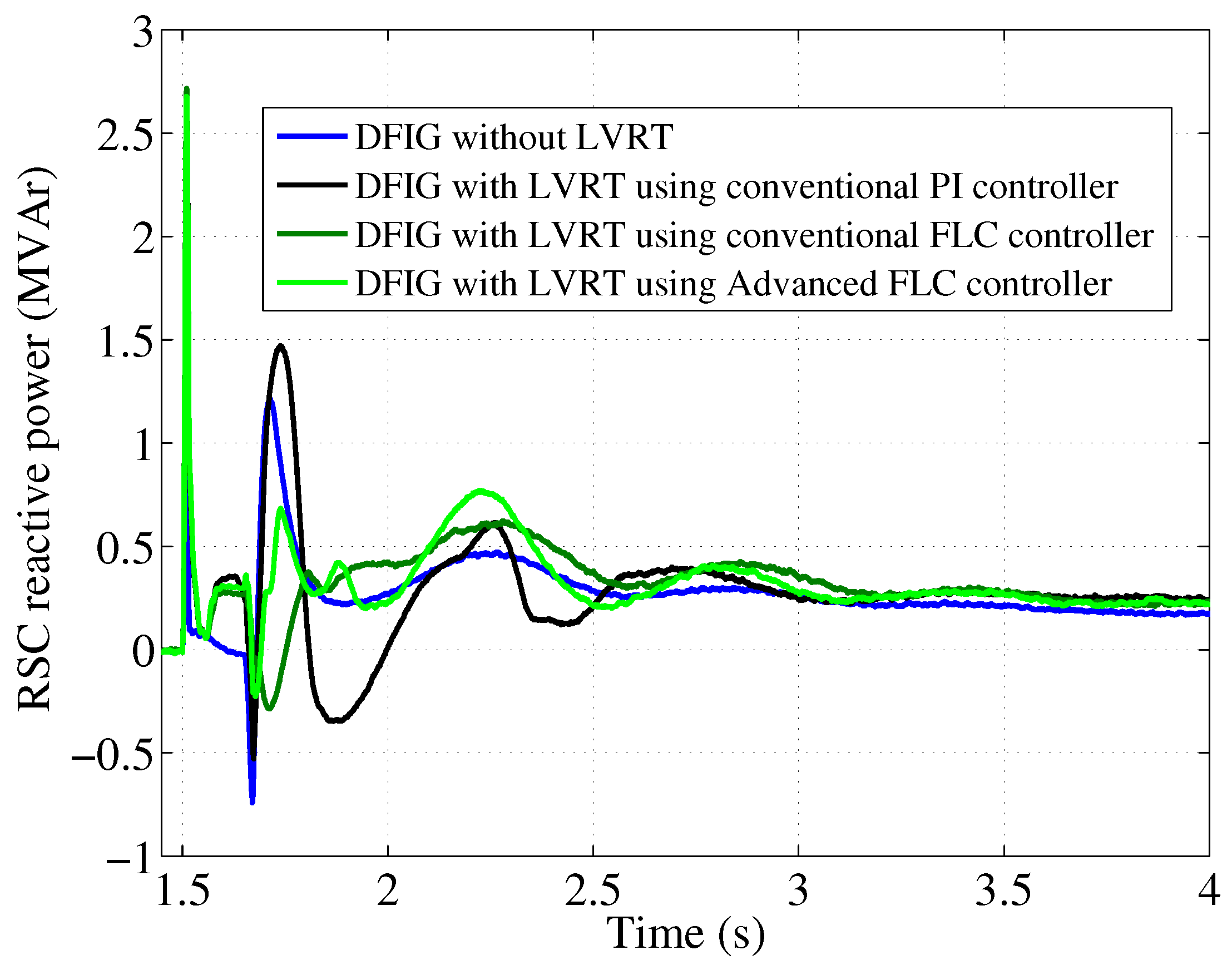
Figure 17.
The DFIG active power output.
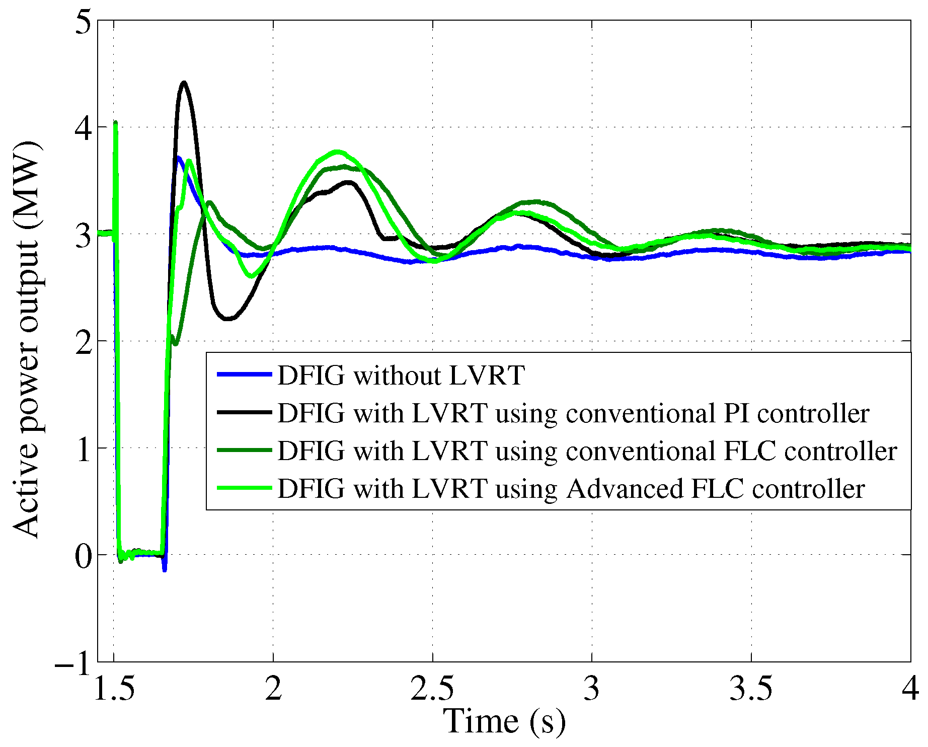
Figure 18.
Rise time, settling time, and other typical second-order step-response characteristics of the PCC voltage .
Figure 18.
Rise time, settling time, and other typical second-order step-response characteristics of the PCC voltage .


Table 1.
Fuzzy Pitch Angle Regulator Rules During Transient-State.
| du | Error | ||||||||
|---|---|---|---|---|---|---|---|---|---|
| dt | NL | NM | NS | N | ZO | P | PS | PM | PL |
| N | N | NM | NS | N | N | ZO | P | PS | PM |
| ZO | NL | NM | NS | N | ZO | P | PS | PM | PL |
| P | NM | NS | N | ZO | P | P | PS | PM | PL |
Table 2.
Grid Connected Wind Turbine Parameters.
| Parameters | Value | Unit |
|---|---|---|
| DFIG: | ||
| Rated power | 3 | MW |
| Rated speed | 12 | m/s |
| Cut in wind speed | 5 | m/s |
| Cut out wind speed | 19 | m/s |
| Rated Voltage | 690 | V |
| Frequency | 50 | Hz |
| 0.016 | pu | |
| 0.00549 | pu | |
| 0.18 | pu | |
| 0.16 | pu | |
| 2.9 | pu | |
| Grid power source: | ||
| Rated capacity | 12/110 | MVA/kV |
| Short-circuit ratio | 1 |
Table 3.
Performance Analysis for Advanced FLC, FLC and PI controller in terms of PCC voltage.
| Controller | ||||
|---|---|---|---|---|
| Advanced FLC: | 1 | 2 | 0.8 | 0.2 |
| FLC: | 3 | 5 | 1.5 | 0.3 |
| PI: | 3 | 40 | 1.5 | 1 |
© 2018 by the authors. Licensee MDPI, Basel, Switzerland. This article is an open access article distributed under the terms and conditions of the Creative Commons Attribution (CC BY) license (http://creativecommons.org/licenses/by/4.0/).
Share and Cite
MDPI and ACS Style
Duong, M.Q.; Leva, S.; Mussetta, M.; Le, K.H. A Comparative Study on Controllers for Improving Transient Stability of DFIG Wind Turbines During Large Disturbances. Energies 2018, 11, 480. https://doi.org/10.3390/en11030480
AMA Style
Duong MQ, Leva S, Mussetta M, Le KH. A Comparative Study on Controllers for Improving Transient Stability of DFIG Wind Turbines During Large Disturbances. Energies. 2018; 11(3):480. https://doi.org/10.3390/en11030480
Chicago/Turabian StyleDuong, Minh Quan, Sonia Leva, Marco Mussetta, and Kim Hung Le. 2018. "A Comparative Study on Controllers for Improving Transient Stability of DFIG Wind Turbines During Large Disturbances" Energies 11, no. 3: 480. https://doi.org/10.3390/en11030480
Note that from the first issue of 2016, this journal uses article numbers instead of page numbers. See further details here.