Enhanced Control for Improving the Operation of Grid-Connected Power Converters under Faulty and Saturated Conditions

 ,
, 
Abstract
:1. Introduction
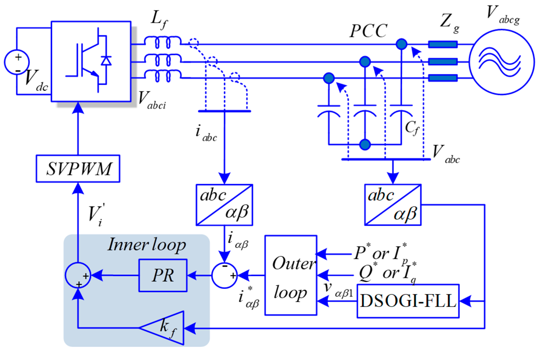
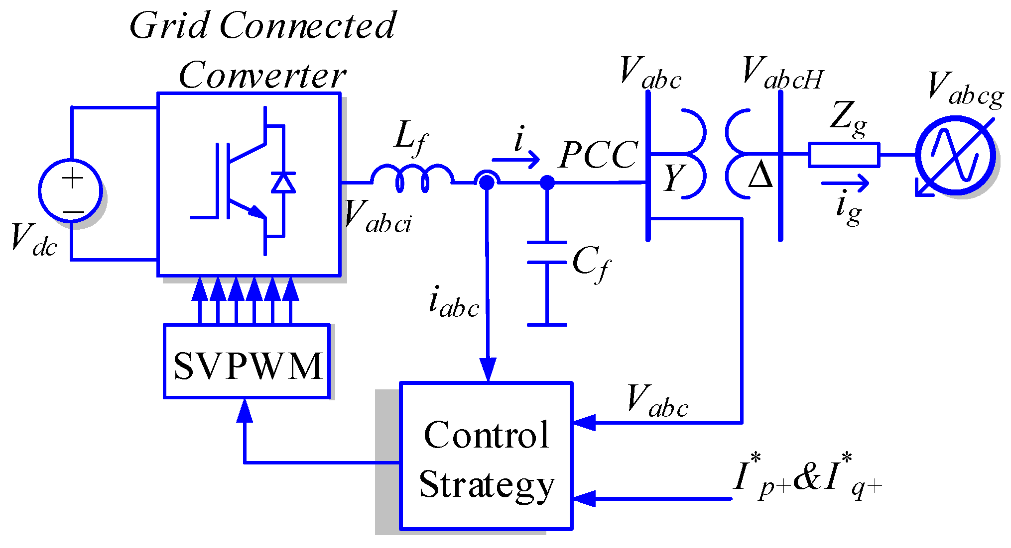
2. Control Strategy
2.1. Saturation and Uncontrollability Scenarios of a GC-VSC
- (1)
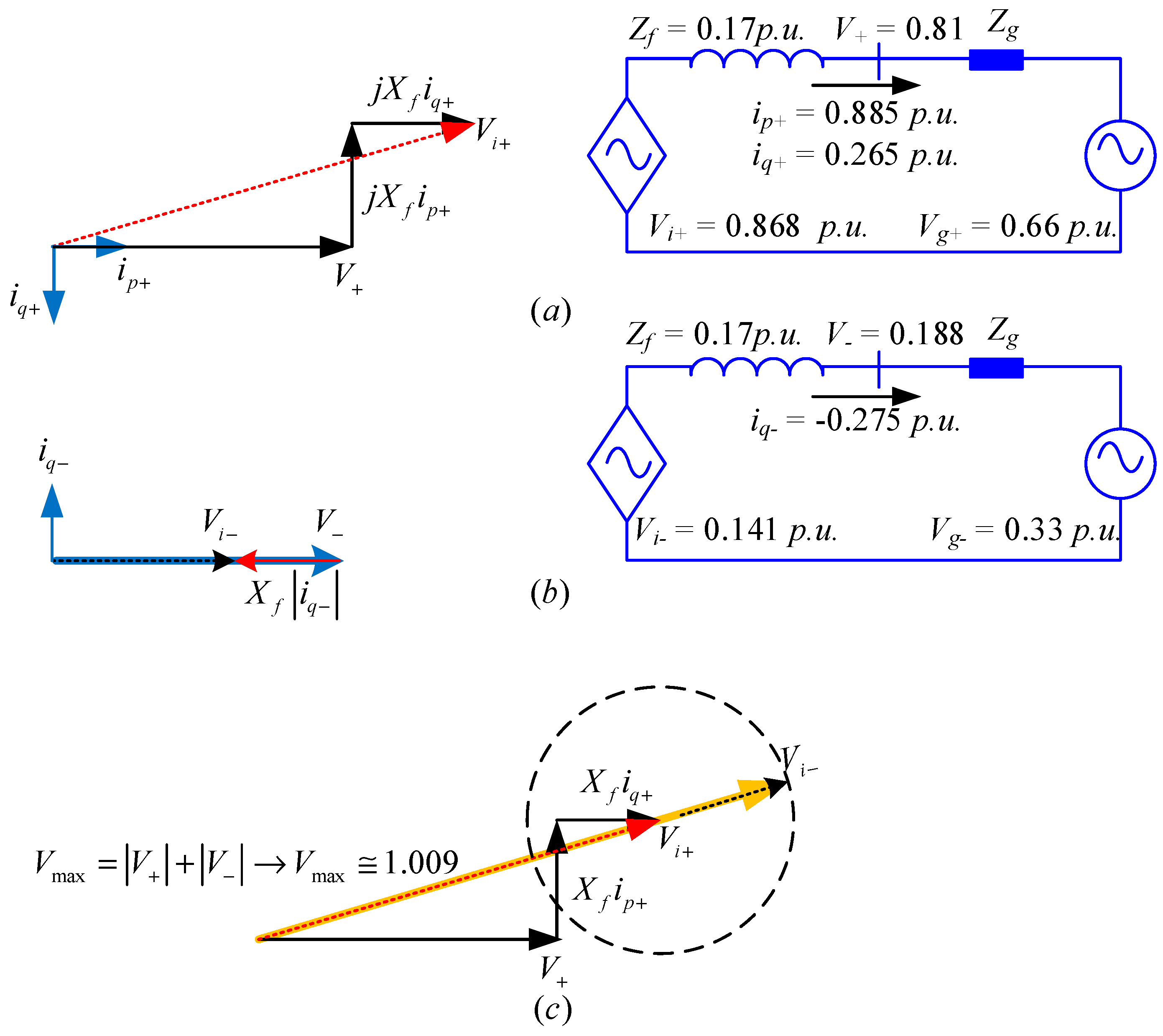
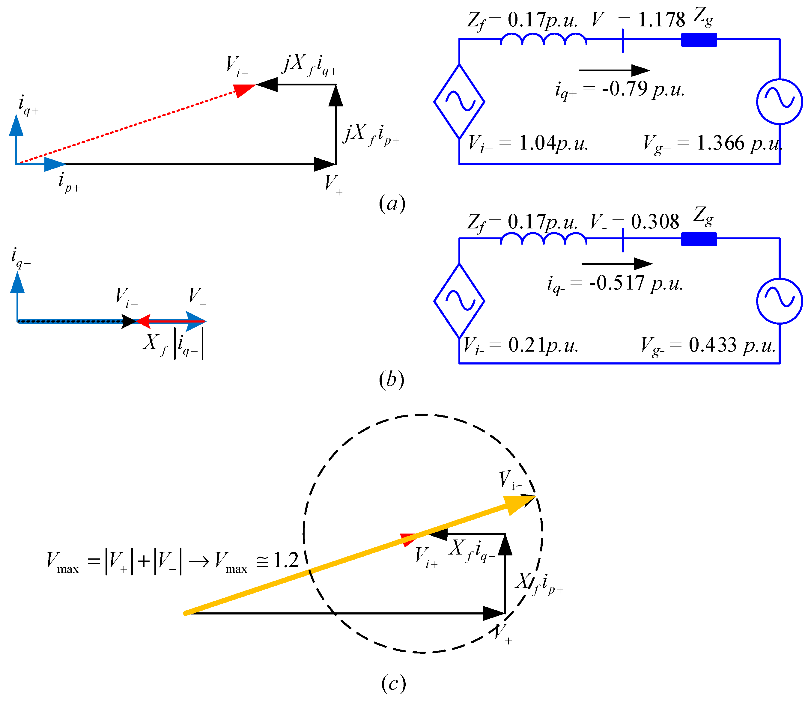
- Using a space vector modulation the linear control range of the output fundamental component can be extended a 15%. However, for a six-step square-wave controlled inverter, the magnitude of the output fundamental voltage is equal to (2/π) Vdc = 0.6366 Vdc. Increasing the output voltage of a PWM-controlled inverter from 0.575 Vdc to the limit of 0.6366 Vdc, is done by entering to the nonlinear region. The region of operation between the loss of linear control (m = 1.15) and complete loss of control (uncontrollability) (m = 1.27) is called the over-modulation region. When over modulation occurs, the modulation index m exceeds the triangle wave in modulator. Note that when m > 1, or m > 1.15 as appropriate, the actual resultant fundamental component does not linearly follow m, and the controller is saturated. Consequently, the shape of the output voltage waveform is only partially under control. Since the modulator effectively loses control of the output waveform during the saturation intervals, the output waveform becomes progressively distorted and includes low-frequency harmonics [29]. Therefore, the amplitude and phase of Vi is determined by the input voltage of the switching modulator, the switching method and the dc bus voltage Vdc. The peak of Vi cannot be higher than 0.6366 Vdc for any switching methods. When an inverter works in grid-supporting mode or grid-feeding mode, the inverter voltage has to be higher than the PCC voltage to deliver reactive power to the grid. To inject reactive power, if the input of switching modulator is higher than triangle wave, the current controller becomes saturated, hence the inverter becomes uncontrollable and the waveforms of the injected current gets distorted.
- (2)
- The GC-VSC current has to be under the semiconductor’s current rating. In transient conditions, as for instance: power/current reference sudden change, inverter’s start-up or when there is a grid fault, the inverter current may experience some overshoots, due to the delay of the current controller, and the wind-up effect at the integrators of the controllers. However, a high current overshoot might give rise to an undesired converter trip or to a critical damage of the semiconductors.
- (3)
- The GC-VSC should help the grid in case of grid faults according to the Low Voltage Ride Through (LVRT) curve. Typically the reactive current coefficient kv± is higher than 2 [23,28]; therefore the active current should be set to zero under severe grid faults to keep the VSC current under the rated value.
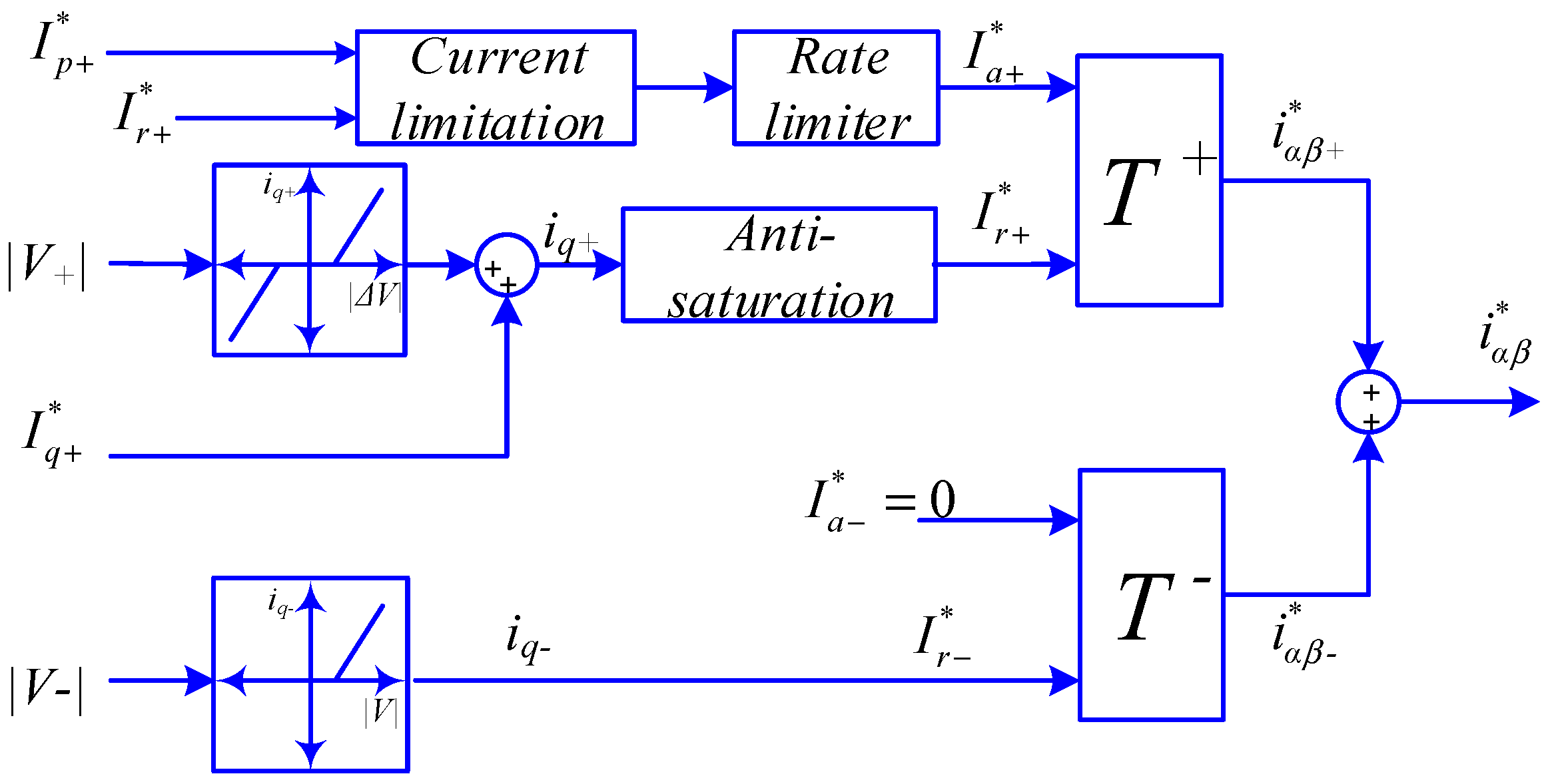
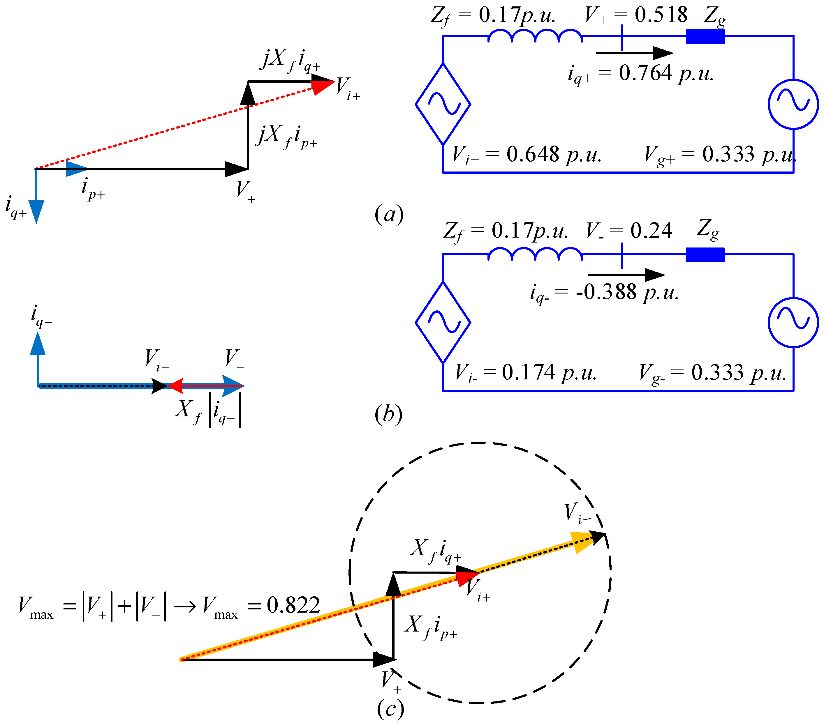
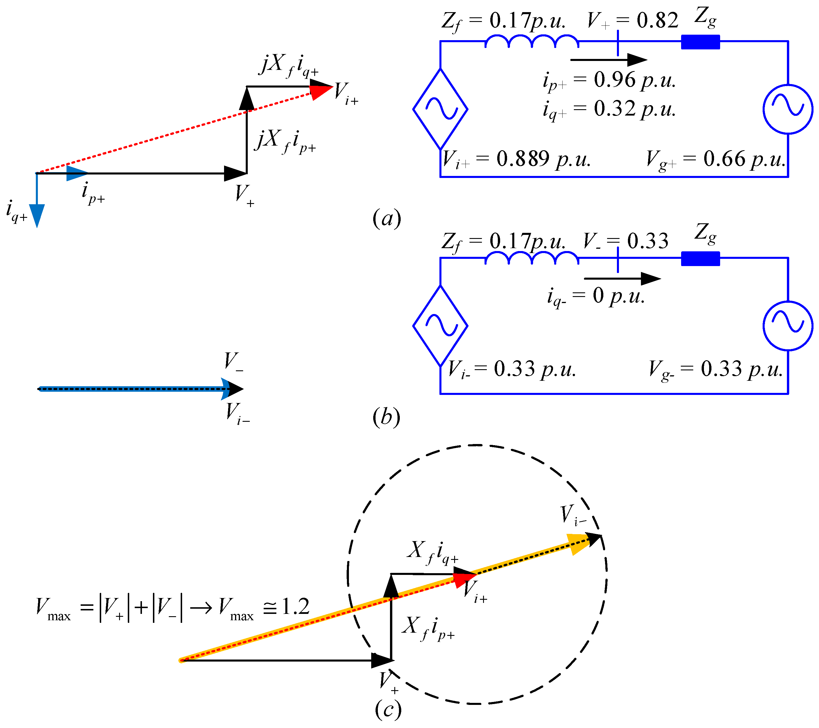
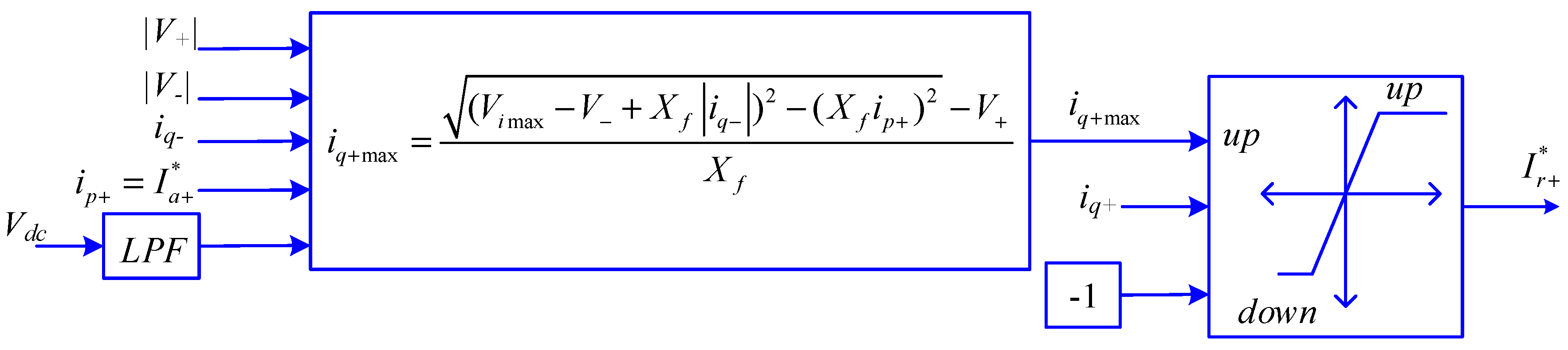
2.2. Development of the Proposed Anti-Saturation Scheme
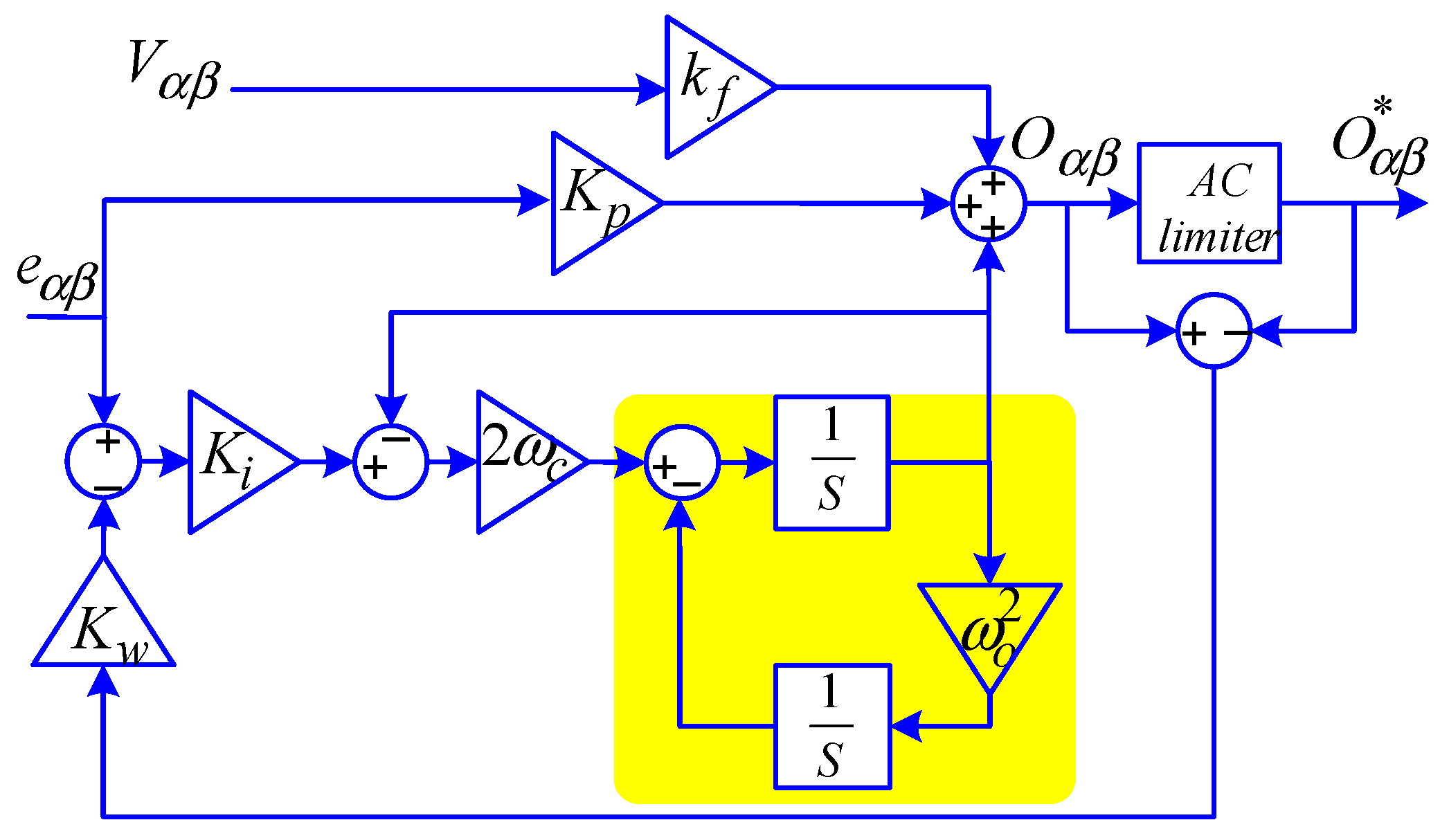
2.3. PR Controller with Anti-Windup Capability
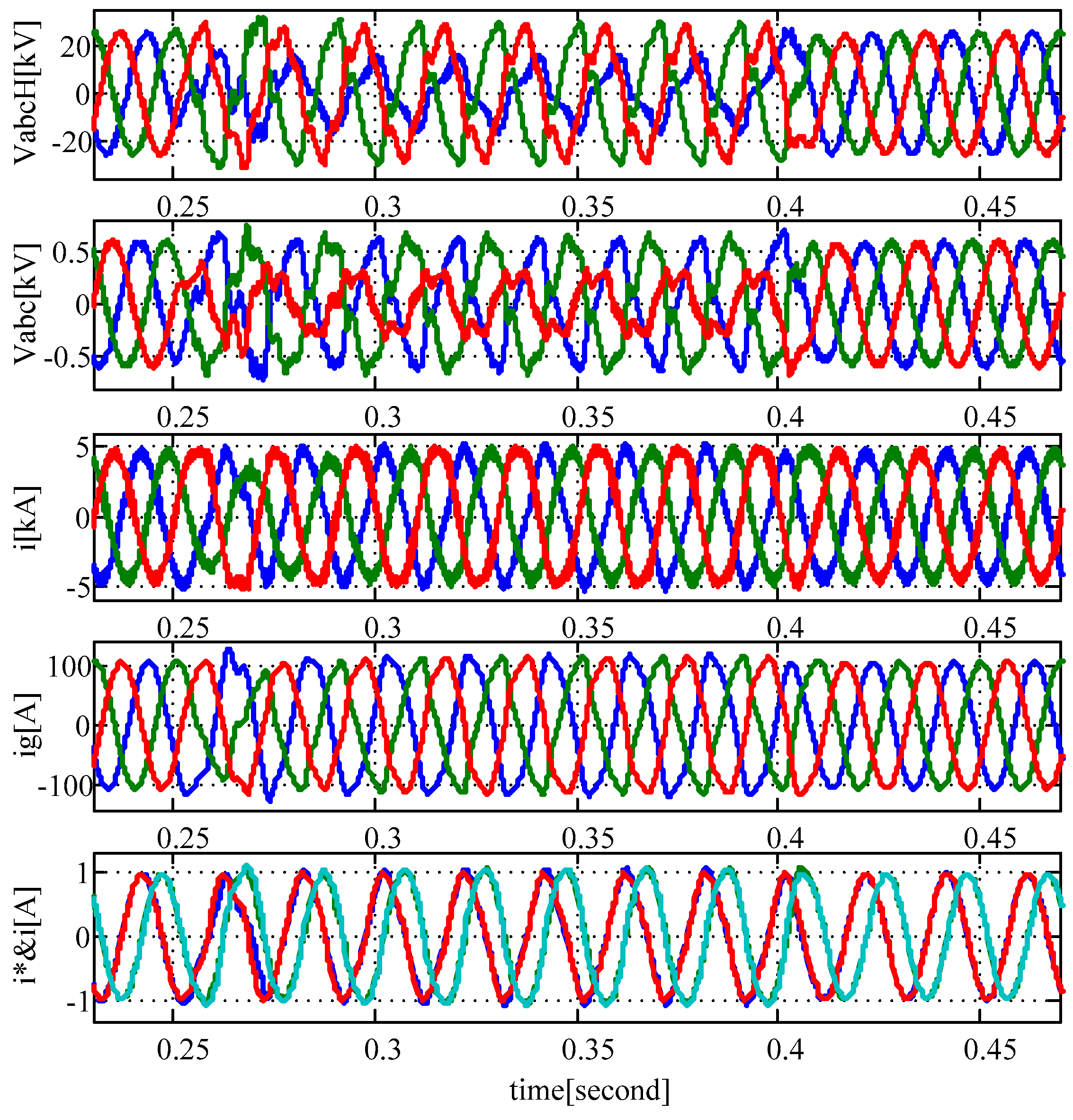
3. Real Time Simulation Results
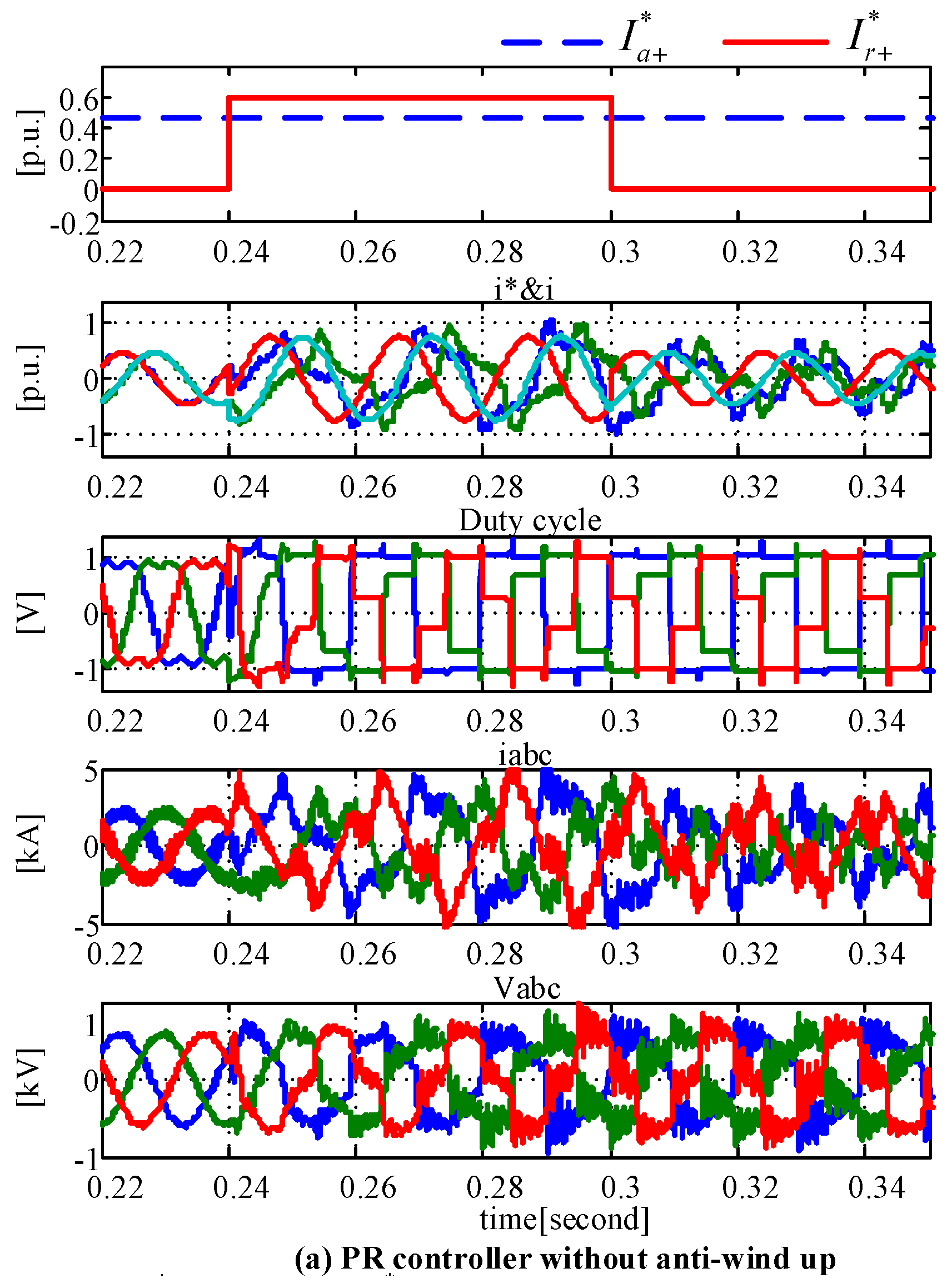
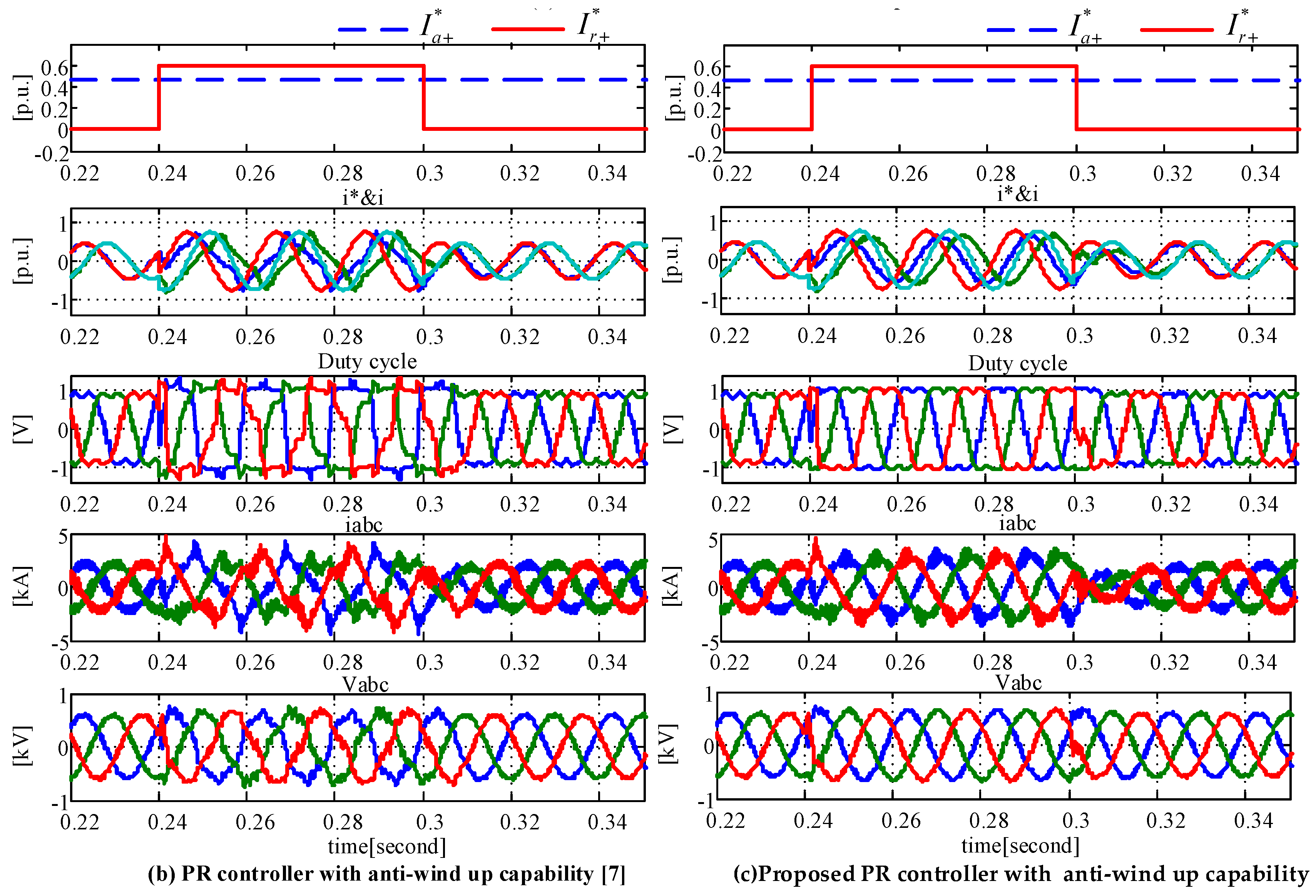
3.1. Test of the PR Controller with Anti-Windup Capability
3.2. Test of the Entire Proposed Scheme
4. Conclusions
Acknowledgments
Author Contributions
Conflicts of Interest
Nomenclature
| AC | Alternating Current |
| DC | Direct Current |
| Cf | capacitor of LC filter |
| IGBT | Insulated-Gate Bipolar Transistor |
| iabc | current of the converter |
| iabcg | current of the grid |
| i*α+, i*β+ | positive sequence components of converter current reference in stationary reference frame |
| i*α−, i*β− | negative sequence components of converter current reference in stationary reference frame |
| ip+, iq+ | active and reactive components of inverter current in positive sequence |
| ip−, iq− | active and reactive components of inverter current in negative sequence |
| I*a+, I*r+ | set points of active and reactive current in positive sequence |
| I*a−, I*r− | set points of active and reactive current in negative sequence |
| I*p+, I*q+ | active and reactive current command in positive sequence |
| f | fundamental frequency in Hz |
| FLL | frequency locked loop |
| kf | feedforward gain |
| Kp | proportional gain |
| Ki | resonant gain |
| Kw | anti-windup gain |
| kv± | droop coefficient |
| LC filter | Inductor-Capacitor filter |
| LPF | Low Pass Filter |
| KVL | Kirchhoff’s Voltage Law |
| LVRT | Low Voltage Ride Through |
| Lf | inductor of LC filter |
| m | modulation index |
| mmax | maximum modulation index |
| Oα, Oβ | output of PR controller with two integrators |
| O*α, O*β | output of PR controller after modification by anti-wind up or limiter |
| PCC | point of common coupling |
| P* | active power reference |
| P | active power injected by the inverter to the PCC |
| PR | proportional-resonant |
| Q | reactive power injected by the inverter to the PCC |
| Q* | reactive power reference |
| S | apparent power injected by the inverter to the PCC |
| SCR | short circuit ratio |
| SPWM | Sinusoidal Pulse Width Modulation |
| SVPWM | Space Vector Pulse Width Modulation |
| tdead | switching dead time |
| Ts | switching period |
| Vdc | DC bus voltage |
| Vabc | phase voltages of the PCC |
| Vabcg | phase voltages of the grid |
| Vabci | output voltage of inverter |
| Vi | space vector of output voltage of inverter |
| Vg | space vector of grid voltage |
| Vα1+, Vβ1+ | fundamental components of positive sequence of PCC voltage in stationary reference frame |
| Vα1−, Vβ1− | fundamental components of negative sequence of PCC voltage in stationary reference frame |
| V+, V− | space vector of PCC voltage in positive and negative sequences |
| Vαg1+, Vβg1+ | fundamental components of positive sequence of grid voltage in stationary reference frame |
| Vαg1−, Vβg1− | fundamental components of negative sequence of grid voltage in stationary reference frame |
| Vg+, Vg− | space vector of grid voltage in positive and negative sequences |
| Zg | equivalent grid impedance |
| Zf = Xf = 2πfLf | impedance of Lf |
| ωo, ωc | resonant frequency in rad/s and resonant bandwidth in rad/s |
Subscripts and Superscripts
| a,b,c | Phase |
| i | Inverter |
| g | Grid |
| max | Maximum |
| +,− | Positive sequence and negative sequence, respectively |
| * | Reference |
| – | complex conjugate |
References
- Elsaharty, M.A.; Candela, J.I.; Rodriguez, P. Power System Compensation Using a Power Electronics Integrated Transformer. IEEE Trans. Power Deliv. 2017, 8977, 1–11. [Google Scholar] [CrossRef]
- Wang, Y.; Xu, Q.; Ma, Z.; Zhu, H. An Improved Control and Energy Management Strategy of Three-Level NPC Converter Based DC Distribution Network. Energies 2017, 10, 1635. [Google Scholar] [CrossRef]
- Ran, X.; Miao, S.; Wu, Y. Improved adaptive droop control design for optimal power sharing in VSC-MTDC integrating wind farms. Energies 2015, 8, 7100–7121. [Google Scholar] [CrossRef]
- Shahparasti, M.; Mohamadian, M.; Teimourzadeh Baboli, P.; Yazdian, A. Toward Power Quality Management in Hybrid AC–DC Microgrid Using LTC-L Utility Interactive Inverter: Load Voltage—Grid Current Tradeoff. IEEE Trans. Smart Grid 2015, 8, 857–867. [Google Scholar] [CrossRef]
- Pinto, R.; Rodrigues, S.; Wiggelinkhuizen, E.; Scherrer, R.; Bauer, P.; Pierik, J. Operation and Power Flow Control of Multi-Terminal DC Networks for Grid Integration of Offshore Wind Farms Using Genetic Algorithms. Energies 2012, 6, 1–26. [Google Scholar] [CrossRef]
- Baek, J.; Choi, W.; Chae, S. Distributed control strategy for autonomous operation of hybrid AC/DC microgrid. Energies 2017, 10, 373. [Google Scholar] [CrossRef]
- Bottrell, N.; Green, T.C. Comparison of current-limiting strategies during fault ride-through of inverters to prevent latch-up and wind-up. IEEE Trans. Power Electron. 2014, 29, 3786–3797. [Google Scholar] [CrossRef]
- Holmes, D.G.; Lipo, T.A.; McGrath, B.P.; Kong, W.Y. Optimized design of stationary frame three phase AC Current regulators. IEEE Trans. Power Electron. 2009, 24, 2417–2426. [Google Scholar] [CrossRef]
- Zmood, D.N.; Holmes, D.G. Stationary frame current regulation of PWM inverters with zero steady-state error. IEEE Trans. Power Electron. 2003, 18, 814–822. [Google Scholar] [CrossRef]
- Shahparasti, M.; Mohamadian, M.; Yazdian, A.; Amini, M. Derivation of a Stationary-Frame Single Loop Controller for Three Phase Standalone Inverter Supplying Nonlinear Loads. IEEE Trans. Power Electron. 2013, 29, 5063–5071. [Google Scholar] [CrossRef]
- Zou, C.; Liu, B.; Duan, S.; Li, R. Stationary Frame Equivalent Model of Proportional-Integral Controller in dq Synchronous Frame. IEEE Trans. Power Electron. 2014, 29, 4461–4465. [Google Scholar] [CrossRef]
- González-Espín, F.; Garcerá, G.; Patrao, I.; Figueres, E. An adaptive control system for three-phase photovoltaic inverters working in a polluted and variable frequency electric grid. IEEE Trans. Power Electron. 2012, 27, 4248–4261. [Google Scholar] [CrossRef]
- Doval-Gandoy, J.; López, Ó.; Malvar, J.; Yepes, A.G.; Freijedo, F.D.; Vidal, A. Transient response evaluation of stationary-frame resonant current controllers for grid-connected applications. IET Power Electron. 2014, 7, 1714–1724. [Google Scholar] [CrossRef]
- Yepes, A.G.; Freijedo, F.D.; Doval-Gandoy, J.; López, Ó.; Malvar, J.; Fernandez-Comesaña, P. Effects of discretization methods on the performance of resonant controllers. IEEE Trans. Power Electron. 2010, 25, 1692–1712. [Google Scholar] [CrossRef]
- Teodorescu, R.; Liserre, M.; Rodriguez, P. Grid Converters for Photovoltaic and Wind Power Systems; John Wiley & Sons: Hoboken, NJ, USA, 2010. [Google Scholar]
- Perić, L.S.; Vukosavić, S.N. Modified digital current controller with reduced impact of transport delays. IET Electr. Power Appl. 2016, 10, 517–525. [Google Scholar] [CrossRef]
- Guo, X.Q.; Wu, W.Y. Improved current regulation of three-phase grid-connected voltage-source inverters for distributed generation systems. IET Renew. Power Gener. 2010, 4, 101–105. [Google Scholar] [CrossRef]
- Li, S.; Wang, X.; Yao, Z.; Li, T.; Peng, Z. Circulating current suppressing strategy for MMC-HVDC based on nonideal proportional resonant controllers under unbalanced grid conditions. IEEE Trans. Power Electron. 2015, 30, 387–397. [Google Scholar] [CrossRef]
- Kuperman, A. Proportional-Resonant Current Controllers Design Based on Desired Transient Performance. IEEE Trans. Power Electron. 2015, 30, 5341–5345. [Google Scholar] [CrossRef]
- Pereira, L.F.A.; Bazanella, A.S. Tuning Rules for Proportional Resonant Controllers. IEEE Trans. Control Syst. Technol. 2015, 23, 2010–2017. [Google Scholar] [CrossRef]
- Xin, Z.; Wang, X.; Qin, Z.; Lu, M.; Loh, P.C.; Blaabjerg, F. An Improved Second-Order Generalized Integrator Based Quadrature Signal Generator. IEEE Trans. Power Electron. 2016, 31, 8068–8073. [Google Scholar] [CrossRef]
- Zhang, W.; Remon, D.; Cantarellas, A.M.; Rodriguez, P. A unified current loop tuning approach for grid-connected photovoltaic inverters. Energies 2016, 9, 723. [Google Scholar] [CrossRef]
- Neumann, T.; Wijnhoven, T.; Deconinck, G.; Erlich, I. Enhanced dynamic voltage control of type 4 wind turbines during unbalanced grid faults. IEEE Trans. Energy Convers. 2015, 30, 1650–1659. [Google Scholar] [CrossRef]
- Tomaszewski, E.; Jiangy, J. An Anti-Windup Scheme for Proportional Resonant controllers with tuneable phase-shift in Voltage Source Converters. In Proceedings of the Power and Energy Society General Meeting (PESGM), Boston, MA, USA, 17–21 July 2016. [Google Scholar] [CrossRef]
- Shahparasti, M.; Catalán, P.; Candela, J.I.; Luna, A.; Rodríguez, P. Advanced control of a high power converter connected to a weak grid. In Proceedings of the 2016 IEEE Energy Conversion Congress and Exposition (ECCE), Milwaukee, WI, USA, 18–22 September 2016; pp. 1–7. [Google Scholar]
- Rodríguez, P.; Luna, A.; Candela, I.; Mujal, R.; Teodorescu, R.; Blaabjerg, F. Multiresonant frequency-locked loop for grid synchronization of power converters under distorted grid conditions. IEEE Trans. Ind. Electron. 2011, 58, 127–138. [Google Scholar] [CrossRef] [Green Version]
- Muñoz-Aguilar, R.S.; Rodríguez, P.; Dòria-Cerezo, A.; Candela, I.; Luna, A. A sensor-less sliding mode control scheme for a stand-alone wound rotor synchronous generator under unbalanced load conditions. Int. J. Electr. Power Energy Syst. 2014, 60, 275–282. [Google Scholar] [CrossRef]
- VDE. VDE-AR-N 4120, Technical Requirements for the Connection and Operation of Customer Installations to the High Voltage Network (TAB High Voltage); VDE: Frankfurt am Main, Germany, 2015. [Google Scholar]
- Holmes, D.G.; Lipo, T.A. Pulse Width Modulation for Power Converters: Principles and Practice; Wiley-IEEE Press: Hoboken, NJ, USA, 2003. [Google Scholar]


| Variable | Value | Variable | Value |
|---|---|---|---|
| V (Vrms) | 690 | Cf (μF) | 1000 |
| SNOM (MVA) | 4 | fO (Hz) | 50 |
| Vdc (V) | 1150 | fS (kHz) | 2 |
| Lf (μH) | 65 | SCR | 5 |
© 2018 by the authors. Licensee MDPI, Basel, Switzerland. This article is an open access article distributed under the terms and conditions of the Creative Commons Attribution (CC BY) license (http://creativecommons.org/licenses/by/4.0/).
Share and Cite
Shahparasti, M.; Catalán, P.; Roslan, N.F.; Rocabert, J.; Muñoz-Aguilar, R.-S.; Luna, A. Enhanced Control for Improving the Operation of Grid-Connected Power Converters under Faulty and Saturated Conditions. Energies 2018, 11, 525. https://doi.org/10.3390/en11030525
Shahparasti M, Catalán P, Roslan NF, Rocabert J, Muñoz-Aguilar R-S, Luna A. Enhanced Control for Improving the Operation of Grid-Connected Power Converters under Faulty and Saturated Conditions. Energies. 2018; 11(3):525. https://doi.org/10.3390/en11030525
Chicago/Turabian StyleShahparasti, Mahdi, Pedro Catalán, Nurul Fazlin Roslan, Joan Rocabert, Raúl-Santiago Muñoz-Aguilar, and Alvaro Luna. 2018. "Enhanced Control for Improving the Operation of Grid-Connected Power Converters under Faulty and Saturated Conditions" Energies 11, no. 3: 525. https://doi.org/10.3390/en11030525