Line-Interactive Transformerless Uninterruptible Power Supply (UPS) with a Fuel Cell as the Primary Source
by
 ,
,
Muhammad Iftikhar
1, 
Muhammad Aamir
2,*,
Asad Waqar
2,
Naila
2,
Fahad Bin Muslim
3 and
Imtiaz Alam
2 1
Department of Electrical Engineering, University of Engineering and Technology, 25000 Peshawar, Pakistan
2
Department of Electrical Engineering, Bahria University, 44000 Islamabad, Pakistan
3
Department of Electrical Engineering, Iqra University, 44000 Islamabad, Pakistan
*
Author to whom correspondence should be addressed.
Energies 2018, 11(3), 542; https://doi.org/10.3390/en11030542
Submission received: 8 December 2017
/
Revised: 6 February 2018
/
Accepted: 7 February 2018
/
Published: 2 March 2018
Abstract
:This paper presents line-interactive transformerless Uninterruptible Power Supply (UPS) with a fuel cell as the prime energy source. The proposed UPS consists of three major parts (i.e., an output inverter, a unidirectional DC–DC converter, and a battery charger/discharger). Non-isolated topologies of both the unidirectional converter and battery charger/discharger ensure transformerless operation of the UPS system. A new topology of high gain converter is employed for boosting the low voltage of the fuel cell to a higher DC link voltage, with minimum semiconductor count, and high efficiency. A high-gain battery charger/discharger realizes the bidirectional operation between the DC link and the battery bank. Besides, it regulates the DC link voltage during the cold start of fuel cells and keeps the battery bank voltage to only 24 V. A new inverter control scheme is introduced that regulates the output voltage and minimizes the total harmonic distortion for non-linear loading condition. The proposed control scheme integrates proportional-resonant control with slide mode control, which improves the controller’s performance in transient conditions. The proposed UPS system is validated by developing a 1-kVA experimental prototype.
1. Introduction
Uninterruptible power supplies (UPS) are extensively delivering backup power to sensitive loads (e.g., data servers, medical equipment, communication devices, etc.) [1,2]. Normally UPS systems provide high efficiency and high reliability, with an additional important feature of fast response during change of modes [3,4].
Generally, a lead acid or Ni–Cad battery is used to provide backup power in a UPS system. However, the battery-based UPS has disadvantages of short life span, low reliability, high maintenance cost of the batteries [5], etc. On the other hand, fuel cells have a longer backup time, higher power density, lower maintenance cost, and longer life time, and hence are an excellent alternative to lead acid batteries [6,7,8,9].
Line-interactive UPS is a suitable choice for hybrid energy storage system. In line-interactive UPS, the main grid and local load are connected in parallel with the UPS system. They are more reliable, with high efficiency, simple structure, and are much cheaper as compared to the online UPS. However, owing to the slower fuel cell response, a hybrid storage system is introduced to ensure the appropriate UPS operation under different loading conditions. Different hybrid energy storage UPS systems are presented in [10,11,12,13,14,15,16]. Most of these systems employ high-frequency isolated converters for the parallel operation of different energy storage sources. However, an extra number of active switches and galvanic isolation affect the overall efficiency of the system as well as its reliability. On the other hand, a transformerless system can replace isolated systems by providing higher efficiency, higher power density, lower cost, and smaller volume and weight.
Fuel-cell-based transformerless UPS systems have not been extensively investigated yet. In this paper, a transformerless, line-interactive hybrid power source UPS system has been proposed with a fuel cell as the major source of power. A high-gain bidirectional boost converter has been employed between the battery bank and the DC link. At the same time, it works as a unidirectional DC–DC converter (boost mode only), stepping up the lower fuel cell voltage to a much higher DC link voltage. Since the battery provides power for a very short time, i.e., cold start of fuel cells and transients, a small battery bank is more appropriate for this purpose. A high-gain bidirectional charger/discharger ensures the use of a low battery bank of merely 24 V (single battery), which eliminates the problems associated with the combination of series-connected batteries. Since the connected load in the UPS system is non-linear, a novel robust inverter control scheme has been introduced by integrating proportional-resonant (PR) with slide mode and control. The controller reduces the total harmonics distortion (THD) for a non-linear load and regulates the output in both impulsive and step change in load. A 1 kVA experimental prototype of the UPS system has been developed in the laboratory, which validates its performance in dynamic and steady state condition. The proposed system offers several benefits such as:
- A high-gain DC–DC converter is used, which boosts the low voltage of the fuel cell to a higher DC link voltage.
- A novel battery charging/discharging circuit has been introduced, which causes a significant reduction in the battery bank size.
- A robust inverter control scheme has been proposed for both impulse and nonlinear loads.
- The proposed system has higher efficiency and lower cost as compared to its contemporaries.
The remainder of the paper is organized in the following way. In Section 2, the proposed line-interactive UPS system is explained, including the converter topology. In Section 3, an explanation of the control of different subparts of the UPS system is presented. Experimental results from a 1-kW laboratory prototype are presented in Section 4 during load variations. Finally, conclusions are presented in Section 5.
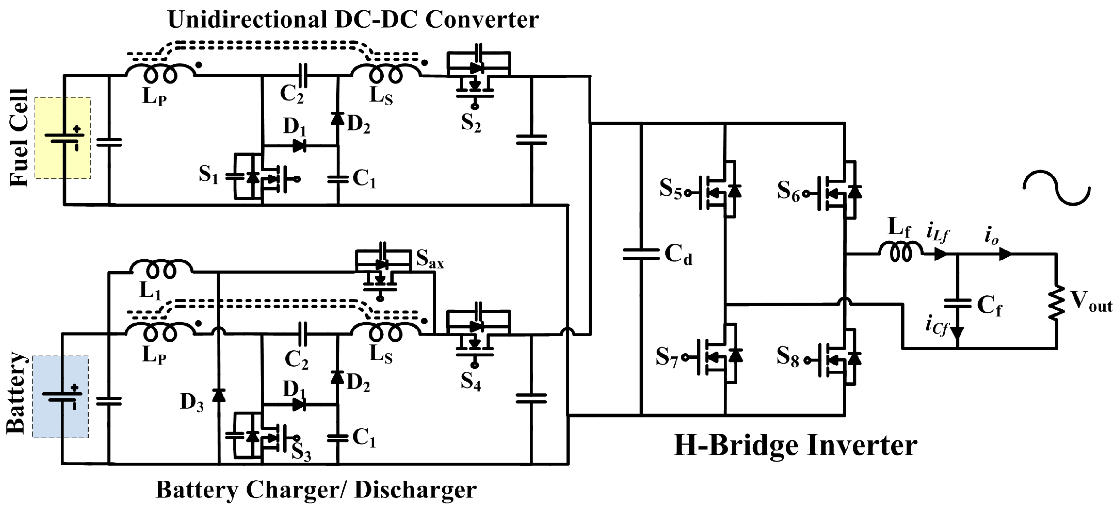
2. Circuit Description
The proposed system consists of a unidirectional DC–DC converter connected to a fuel cell, H-bridge inverter at the back end, and high-gain boost converter connected with the battery bank of the UPS system. Figure 1 shows a schematic of the proposed fuel-cell-based line-interactive UPS system. The UPS system is composed of a unidirectional converter, a bidirectional battery charging/discharging unit, and an H-bridge inverter. The primary source of energy is a fuel cell, while the battery bank is utilized as the transient energy storage. The unidirectional converter acts as an interface between the low-voltage fuel cell and the high-voltage DC link of the inverter. Similarly, a bidirectional converter is employed as a battery charger/discharger, with high voltage conversion ratio, which shrinks the battery bank considerably. A new control scheme has been proposed for the H-bridge inverter that accomplishes output regulation for both linear and non-linear loading conditions.
2.1. Modes of Operation
The proposed UPS system has two distinct operational modes, the grid mode and the fuel cell/battery-powered mode, as depicted in Figure 2.
Grid mode:
In case of a stable grid voltage and no power failure, the grid mode of the UPS is active. The grid directly drives the load. Moreover, the fuel cell feeds the unidirectional converter for regulating the DC link and charging the battery. The bidirectional converter charges and discharges the battery bank.
Fuel cell/battery-powered mode:
In the scenario of power breakdown or any voltage sag at the input, the magnetic contactor (MC) opens, causing the grid to disconnect from the load. Now, the fuel cell and the battery bank supply power to the load. Here the energy storing device, i.e., the battery bank, plays two important roles. Firstly, the batteries handle the short time load mismatch to overcome the slow dynamics of the fuel cell. Secondly, the battery bank overcomes the instantaneous power fluctuations because the PFC stacks may take some time in order to attain the required output voltage as the hydrogen cannot be fed fast enough.
2.2. Model of Fuel Cell
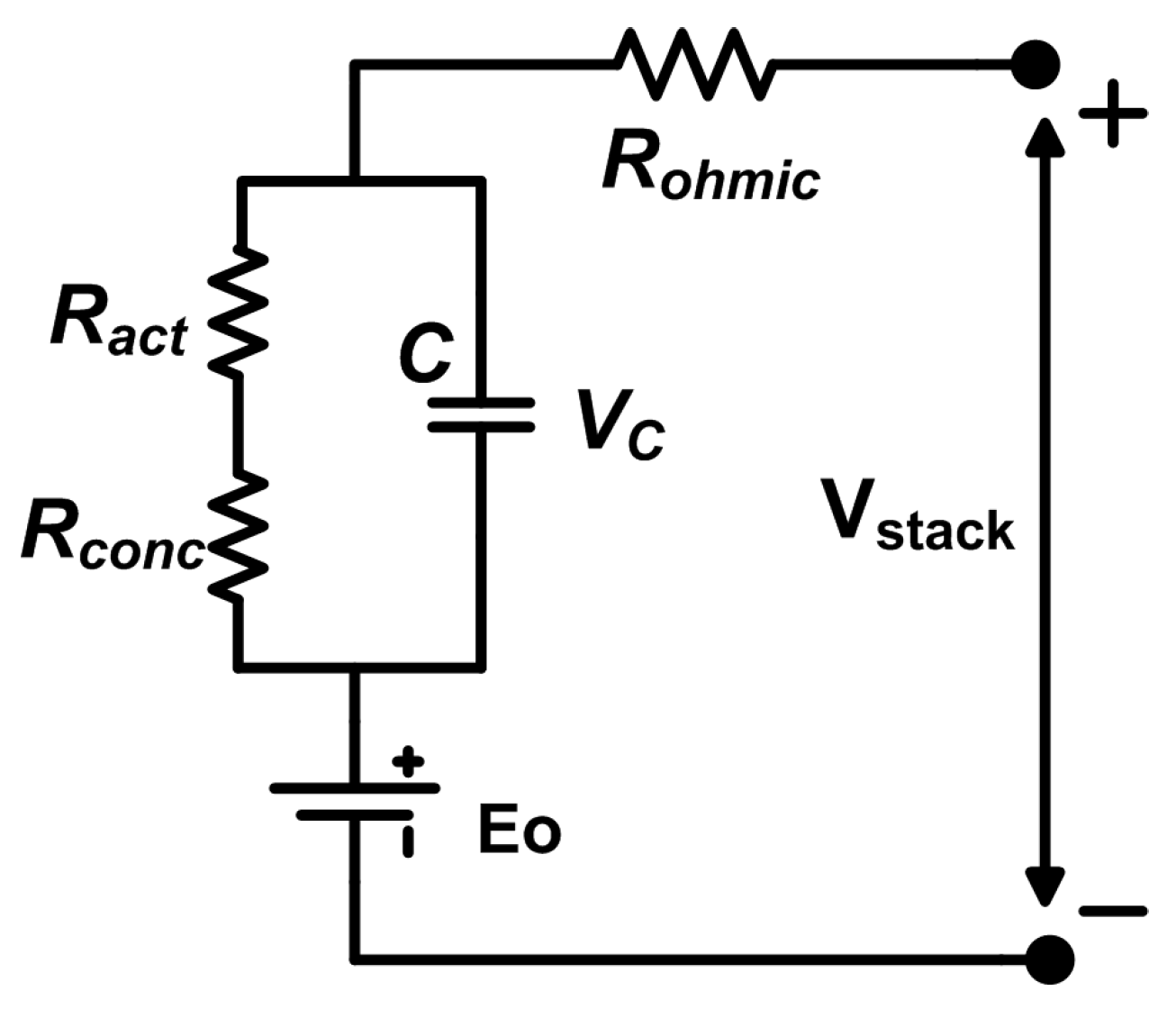
A 1 kW 30 V polymer-electrolyte membrane fuel cell (PEMFC) model based on [17] is used in the proposed system. The total voltage across the FC is the sum of the activation overvoltage, Nernst’s voltage, concentration overvoltage, and ohmic overvoltage. The Nernst’s instantaneous voltage Vcell and the irreversible voltage Virrev give the output voltage from the PEMFC, as given in Equation (1):
where is the open circuit voltage (OCV) at standard temperature and pressure, R is the ideal gas constant, T is the stack temperature (k), F is Faraday’s Constant (C/mol), is a function of the entropy change, , pO2, and pH2 is the partial pressure of water, oxygen, and hydrogen respectively. Similarly Vact, Vconc and Vohm are the activation, concentration, and ohmic voltage drops of the fuel cell.
The equivalent electric model of PEMFC is shown in Figure 3, where C is the equivalent capacitance because of the double-layer charging effect, Vc represents capacitor voltage, Ract indicates the activation resistance, and Rconc is the concentration resistance.
The hydrogen partial pressure can be computed as
where represents gas constant for hydrogen, T is the temperature and Van is the anode’s volume. Similarly and are input flow and reacted flow of the hydrogen gas in the anode, respectively.
where N is the total number of cells required to attain the required output voltage from the fuel cell, and the fuel cell supplied current is represented by IFC.
The hydrogen output flow can be computed using the expression
where can be computed using the relationship between the molar flow and its partial pressure of the hydrogen gas inside the channel as represented as follows:
Similarly, the oxygen partial pressure is given as
where Vcat is the volume of cathode, RO2 is the oxygen gas constant, and , , and are the input, the output, and the reacted oxygen in the cathode, respectively. The H-1000 Horizon FC data have been used in the proposed model, which is presented in Table 1.
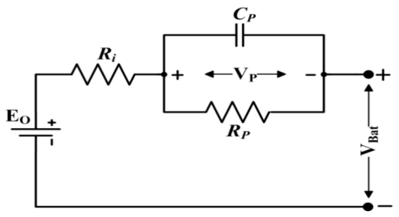
2.3. Battery Model
Figure 4 shows the equivalent electric circuit of the lead acid battery, which represents the Thevenin battery model [18]. Equation (11) represents the battery terminal voltage:
where EO = Ideal voltage of the batter, Ri = Internal resistance, CP = Polarization capacitor, RP = Polarization resistance, VCP = Polarization voltage, NS = Number of cells connected in series, NP = Number of cells connected in parallel, = Battery current.
All the model components are functions of the battery state of charge (SoC). Model parameters corresponding to the battery are given in Table 2.
2.4. Bidirectional DC–DC Converter
A novel non-isolated DC–DC converter (based on a coupled inductor) with bidirectional operation has been proposed, which is separately connected to the fuel cell along with the battery bank. Firstly, it performs the unidirectional operation and boosts the low-level fuel cell voltage to a high-level DC link voltage (boost mode of operation). Secondly, it acts as a battery charging/discharging unit operating between the battery bank and the DC link (both buck and boost modes of operation). The converter offers the following benefits:
- High voltage diversity in both modes of operation, i.e., buck and boost modes.
- Reduced passive components are employed in the proposed converter.
- Bidirectional operation is performed using only three active switches.
- Zero Voltage Switching (ZVS), voltage clamping circuit, and synchronous rectification are used to minimize the conduction and switching losses.
In the proposed bidirectional converter, the coupled inductor is used with primary and secondary windings, represented by LP and LS, respectively. The boost pump capacitor Cb2 provides high voltage diversity, with continuous current flow and reduced current stress in the primary winding of the coupled inductor. The voltage stress of capacitor Cb2 is very low at this point in the circuit.
There are severe voltage and current ripples with twice the output AC frequency in the DC bus. In this case, the current ripples will react with the output terminal of the FCs through the DC/DC converter so that the power sources will sustain extra loads. The low-frequency current ripple and transient load will cause a decrease in FC efficiency [19,20]. However, a passive compensation approach has been used in which the capacitor parallel to the FC and battery bank are selected with slightly larger values, which limits the current and voltage ripples to less than 10%.
2.4.1. Battery Charging/Buck Operation
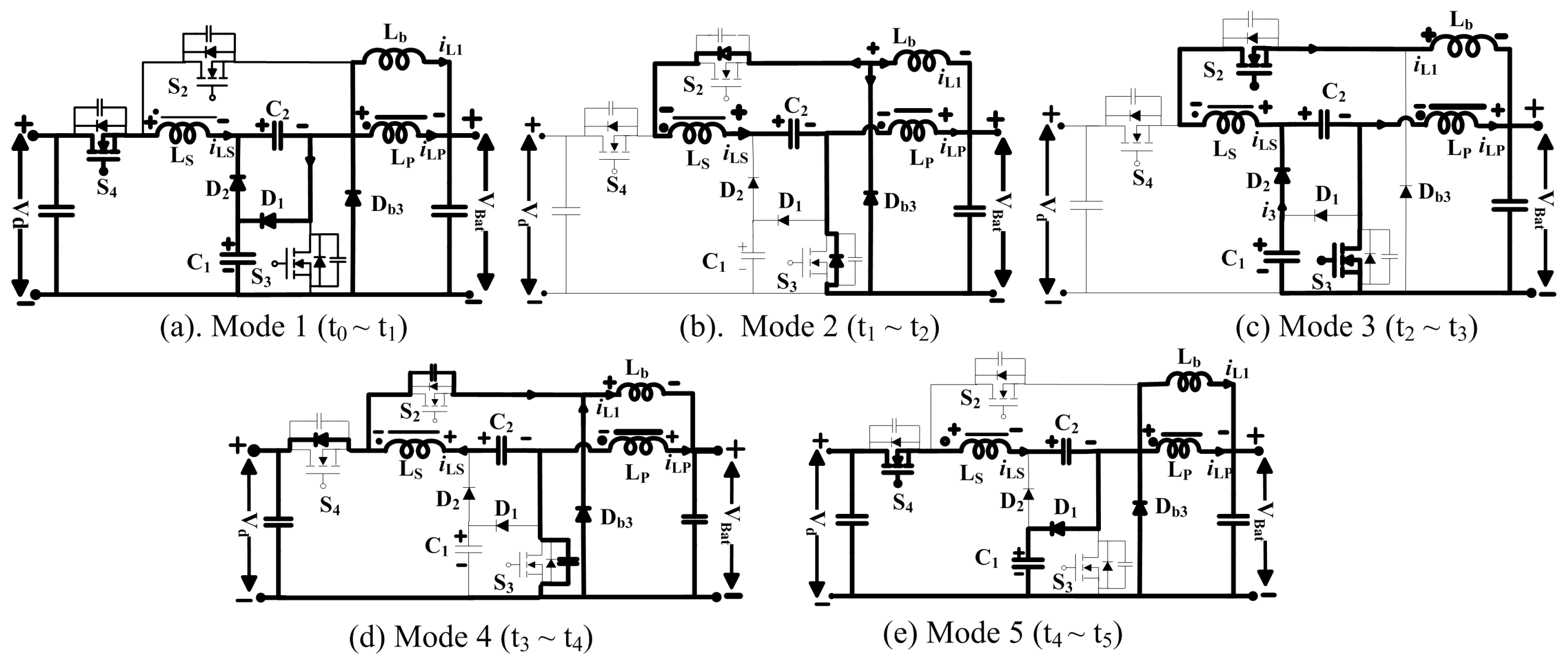
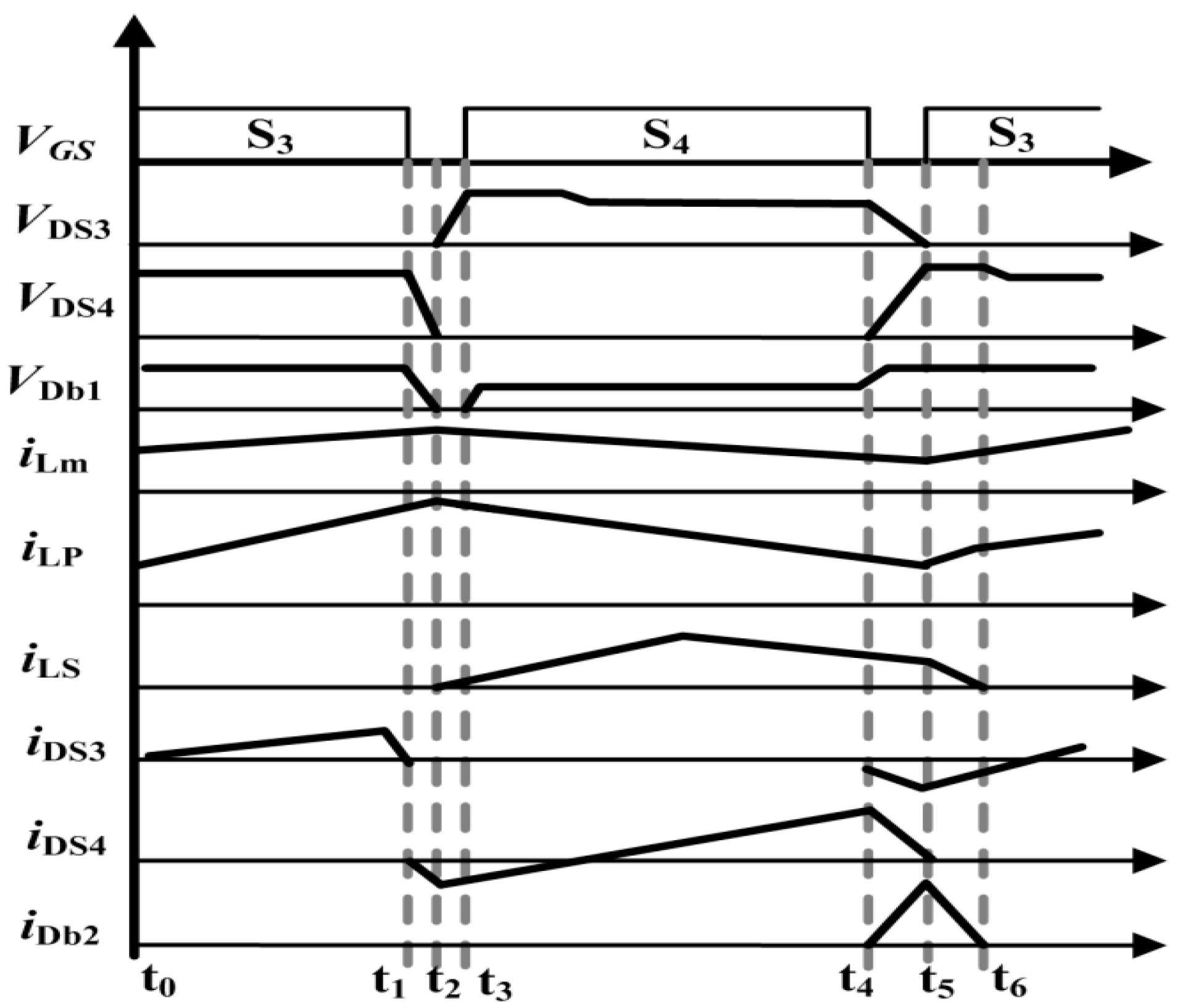
Figure 5 shows the characteristic waveforms during buck mode. D1 is the duty cycle of S3 and Sax, while D3 is the duty cycle of switch S4. D1 and D3 are related to each other by the relationship D1 (=1 − D3). Lm represents the coupled inductor magnetizing inductance having a turns ratio of N = N2/N1, where N1 indicates the number of turns in primary winding and N2 indicates the number of turns for secondary winding. Vd is the voltage across DC link, VBat is the battery voltage, VLP and VLS are the primary and secondary winding voltages, and Vcb2 is the voltage across capacitor Cb2. Figure 6 shows the operation of topology in intervals throughout the battery charging mode.
Interval 1 (t0~t1):
The switch S4 remains ON while the switches S3 & Sax are turned OFF during this interval. The direction of current iLS is from the DC link towards the battery bank via the capacitor Cb2 and the coupled inductor’s windings. Employing KVL, we get Equation (12):
The continuous inductor current iLb flows through the diode Db3 towards the battery bank. VBat represents the voltage across the inductor Lb.
Interval 2 (t1~t2):
When interval 2 starts, switch S4 turns OFF and the polarities of primary and secondary coils (LP & LS) of coupled inductor are reversed because of the energy stored in the leakage inductor. In this mode of operation Switch S4 is OFF, but the secondary current iLS is still flowing, hence the body diode of the switch Sax is forward-biased to ensure that the current iLS keeps on flowing. This mode keeps the diode Db3 in forward bias. Switch S3 body diode is forward-biased with the reduction of the secondary current iLS; however, the primary current iLP remains unchanged.
Interval 3 (t2~t3):
Both S3 and Sax turn ON following zero voltage switching (ZVS) in this mode. The capacitor Cb2 begins to discharge across the battery bank through the switch Sax and the inductor Lb. The discharging capacitor Cb2 causes the secondary current iLS to induce in the reverse direction. The body diode Db2 allows clamp capacitor Cb1 to discharge and adds small current i3 into the secondary current that further flows towards the battery.
By employing the voltage second balance, VCb2 can be determined as follows:
The primary current releases the stored energy in coupled inductor into the battery bank through switch S3. Utilizing the voltage-second balance, the VLb is given by
The VLP can be determined as follows:
Putting Equation (15) and the values of VLb and VLP into Equation (13), the voltage gain during the buck operation mode is given by the equation
Interval 4 (t3~t4):
Both S3 and Sax turn OFF at the beginning of this mode. The currents corresponding to the primary and secondary windings iLP and iLS continue to flow owing to the coupled inductor leakage inductance. The secondary current charges the parasitic capacitance corresponding to S3 and Sax, and discharges the parasitic capacitance corresponding to S4. When the voltage across Sax equals Vd, the S4 body diode turns ON. As this mode ends, the primary current iLP goes on decreasing until it becomes equal to the secondary current iLS.
Interval 5 (t4~t5):
S4 turns ON during this interval under ZVS conditions. The capacitor Cb1 gets charged by the clamped diode Db1 and the primary and secondary currents begin to increase. The circuit repeats from interval 1 at the end of this interval.
2.4.2. Battery Discharging/Boost Operation
Figure 7 shows the bidirectional converter operational waveform in the battery discharging mode of operation. The circuits for both battery discharging and the fuel cell operation are identical. The switch Sax remains OFF during boost operation. The bidirectional converter boosts the low level battery bank voltage to a higher level DC link voltage. Similarly, the low voltage of fuel cell is step up to high DC link voltage by unidirectional operation of the converter. The battery discharging operation during various intervals is depicted in Figure 8.
Interval 1 (t0~t1):
In interval 1, S3 is ON, and S4 remains OFF. Fuel cell/battery bank voltage is provided to the side of the bidirectional converter with low voltage. Before interval 1, the capacitor Cb2 remains charged and the coupled inductor magnetizing current iLM increases in a linear manner, as depicted in Figure 7.
By utilizing KVL, we can determine
Using voltage second balance, the voltage across primary winding VLP can be derived as follows:
Interval 2 (t1~t2):
In interval 2, S3 turns OFF. S3 parasitic capacitance is charged by primary current iLP, while S4 parasitic capacitance is discharged by secondary current iLS. This interval ends when the voltage across S3 and the capacitor voltage VCb1 become equal.
Interval 3 (t2~t3):
S3 is turned OFF in this interval. The primary current iLP decreases, while the secondary current iLS is enhanced due to the coupled inductor leakage inductance. Consequently, the S4 body diode turns ON. Since the S3 voltage becomes higher than that across the capacitor Cb1, the capacitor Cb1 gets charged via diode Db1. Therefore, the voltage stress across the switch is kept low. The capacitor voltage VC1 is given by
Using Equation (18),
Interval 4 (t3~t4):
In this interval, S4 turns ON under the condition of zero voltage switching (ZVS). Both the coupled inductor windings LP and LS, and the boost pump capacitor Cb2 are in series and provide energy to the DC link. The iLS begins to increase until it approaches iLP, after which it follows the iLP till the interval 4 ends. Hence, the energy stored in both the coupled inductor windings discharges across the DC link. Both Db1 and Db2 are reverse-biased in this interval, as depicted in Figure 8d. Applying voltage second balance, we obtain Equation (22):
Interval 5 (t4~t5):
S4 turns OFF during this interval. The current iLS charges the S4 parasitic capacitance. Cb1 begins to discharge across Cb2 via the diode Db2.
By putting Equations (19) and (24) into Equation (23), the voltage gain of the circuit is
The S3 body diode is forward-biased due to the polarities of Cb2 and inductor LP.
Interval 6 (t5~t6):
In interval 6, S3 turns ON following ZVS conditions. Hence the switching losses are reduced and the efficiency of the system is considerably improved. The next switching cycle starts when the voltage across capacitors Cb1 and Cb2 becomes equivalent.
A turn ratio of N = 2 satisfies the operation of unidirectional converter when the fuel cells are connected, and N = 4 for bidirectional conversion between the desired DC link and the battery bank. Table 3 shows a comparison of proposed bidirectional converter with other state-of-the-art works. The proposed converter shows a high conversion ratio as compared to [20,21]. Also, the number of switches is reduced as compared to other converters. In [21] the authors have shown high voltage diversity; however, five switches are used in the circuit, which increases the size and cost of the system.
3. Control Strategy
The control scheme for different parts of the line-interactive UPS system is shown in Figure 9. The inverter operates only during the fuel cell/battery-powered mode. However, the battery charger/discharger switches depend on the mode change. In grid mode, the bidirectional converter follows the battery discharger control, while in fuel cell/battery-powered mode it follows battery charging control, as shown in Figure 9. Similarly, the control scheme for the unidirectional DC–DC converter regulates the inverter DC link voltage during the fuel cell/battery-powered mode of operation.
3.1. Inverter Control
For our proposed UPS topology, a cascaded control algorithm using Slide Mode Control (SMC) and Proportional Resonant (PR) control has been considered to control the inverter output voltage. The slide mode control is used in current loop while the PR control is used in the voltage loop. The chattering phenomenon corresponding to the slide mode control is prevented by utilizing the law of smoothed control in narrow boundary layer. This law, when implemented on the pulse width modulator leads to the inverter operation with a constant switching frequency. Hence, our proposed controller consists of the properties of both the PR control as well as the SMC control. The employed controller exhibits great response with low THD and also shows high stability for non-linear loads.
The schematic diagram of single phase inverter consisting of an LC filter and our proposed controller for non-linear load condition is depicted in Figure 1. Vd indicates the applied DC link voltage, Vout is the output voltage of the filter capacitor Cf. iLf is the current in the inductor Lf and iO represents the output current through the load R, equivalent to iO = Vout/R. The state equations representing the inverter are given as
where .
In order to implement the SMC, the voltage error x1, and its derivative need to be found as:
where
Consider the slide surface equation
where S denotes the sliding surface. The sliding function must be stabilized. To ensure this, the Lyapunov function V(t) = S2/2 needs to be satisfied with the minimum condition , maintaining the scalar at 0 while is stringently kept as a positive constant. Consequently, the stability condition will be .
To ensure the satisfaction of the sliding condition (30), despite the uncertainty regarding the non-linear function dynamics, u is replaced by the following function.
Therefore, it can be seen that the stability condition would be fulfilled if Equation (36) is satisfied. Now, in order to apply the law of sliding control to the inverter, inputting the values of x1 and x2:
As the sliding mode controller inherently possesses the chattering property, it is accompanied by lower control accuracy and high losses in the circuit. Smoothed slide mode control has been implemented to get rid of this inherent chattering phenomenon. This is done by smoothing the control discontinuity in a thin boundary layer neighboring the sliding surface.
where . is the thickness of the boundary layer and . is the width of the boundary layer. Therefore, . is chosen in such a way that all the trajectories beginning at stay inside for all t > 0. Hence, we interpolate S inside , for instance, and replace S by the expression S/. Thus, Equation (38) will become
The smoothing control employs a low pass filter to the local dynamics, thereby eliminating the chattering phenomenon. As stated before, this technique, when applied to the pulse width modulator, also results in a fixed switching frequency operation of the inverter. The control law is required to be tuned extremely precisely so as to obtain a balance between precise tracking and robustness to the uncontrolled dynamics.
The PR controller normally provides a large gain at the fundamental frequency while strictly following the reference sinusoidal signal, decreasing the steady state error, and enhancing the system stability. The ideal PR controller transfer function is given by Equation (41):
where KP is the proportional gain, ω0 represents the resonant frequency, and KR is the resonant gain.
The ideal PR controller provides an infinity gain at the resonant frequency while providing no gain and phase shift at frequencies other than the resonant frequency. Hence, a more appropriate control is a non-ideal PR control, given by Equation (42):
Thus, selecting an appropriate cutoff frequency ωc can make the bandwidth wide and can reduce the sensitivity towards variations in frequency. By using a combination of the PR controller and slide mode control, the performance of the inverter is significantly improved, as the resonance controller provides a better output voltage regulation and can cause a considerable reduction in the net harmonic distortion.
Thus, we can serve the final equation for the inverter control by combining the proportional resonant control and slide mode control for the current loop.
Hence, Equation (43) indicates the dynamic behavior of the inverter utilizing both PR compensator as well as SMC. As the error current in the capacitor consists of the ripples from the inductor, the current peak may achieve high values. So the value must be assigned with great care so as to compensate the slope from the high current ripple corresponding to the capacitor. Thus, the PR controller removes the steady-state error at the resonant frequency or any harmonic at that frequency.
The robustness of the system and its dynamics are determined by , which represents the response time of the system. It can be seen in Equation (43) that a smaller value of leads to a slowly responding system, while higher values of would increase the response time but the system would take much longer to reach the sliding surface. Hence, the optimal value is equal to the inverter switching frequency.
According to [22], the carrier wave slope is represented by , where is the magnitude of the carrier wave and fs is its frequency. The error signal slope to the modulator is given by the expression . The limitation of the pulse width modulator implies that the slope of the error signal must be smaller than the slope of the carrier signal, i.e.
Error signal slope < Carrier signal slope
Hence, the minimum value can be computed using Equation (45):
For designing a controller for an inverter, as depicted in Figure 9, the value of can be derived using Equation (45) by taking into consideration the circuit parameters given in Table 4. KP and KR represent the proportional gain and resonant gain that are selected to obtain a stable response of the PR controller. α represents the division factor that is required to make the output voltage comparable to the reference voltage and is selected by considering the limitations of the electronic circuitry. λ represents the inverter dynamic response and equals the switching frequency of the modulator. Carrier magnitude (Vm) is selected in order to realize the inequality given in Equation (44). The final control parameters derived, ensuring the stable inverter operation, are presented in Table 4.
3.2. Battery Charger and Discharger Control
The controller for the battery charger/discharger during fuel cell/battery powered mode is depicted in Figure 9. During the charging mode, the controller operates in the Constant Current (CC) mode or the Constant Voltage (CV) mode depending on the battery voltage. The battery input current iBat is compelled to follow the reference current iRef in the current loop using the PI compensator given by Equation (46):
where Kp is the proportional gain and Ki is the integral gain of the controller.
In a similar way, the battery voltage is regulated via a voltage loop using the PI compensator, which makes the output battery voltage VBat follow the reference voltage Vref. The current limiter is employed to limit the maximum battery charging current as specified in Table 2. If iref is larger than ilimit, the battery is charged in CC mode. On the other hand, if iref is smaller than ilimit, the battery is charged in CV mode.
4. Experimental Results
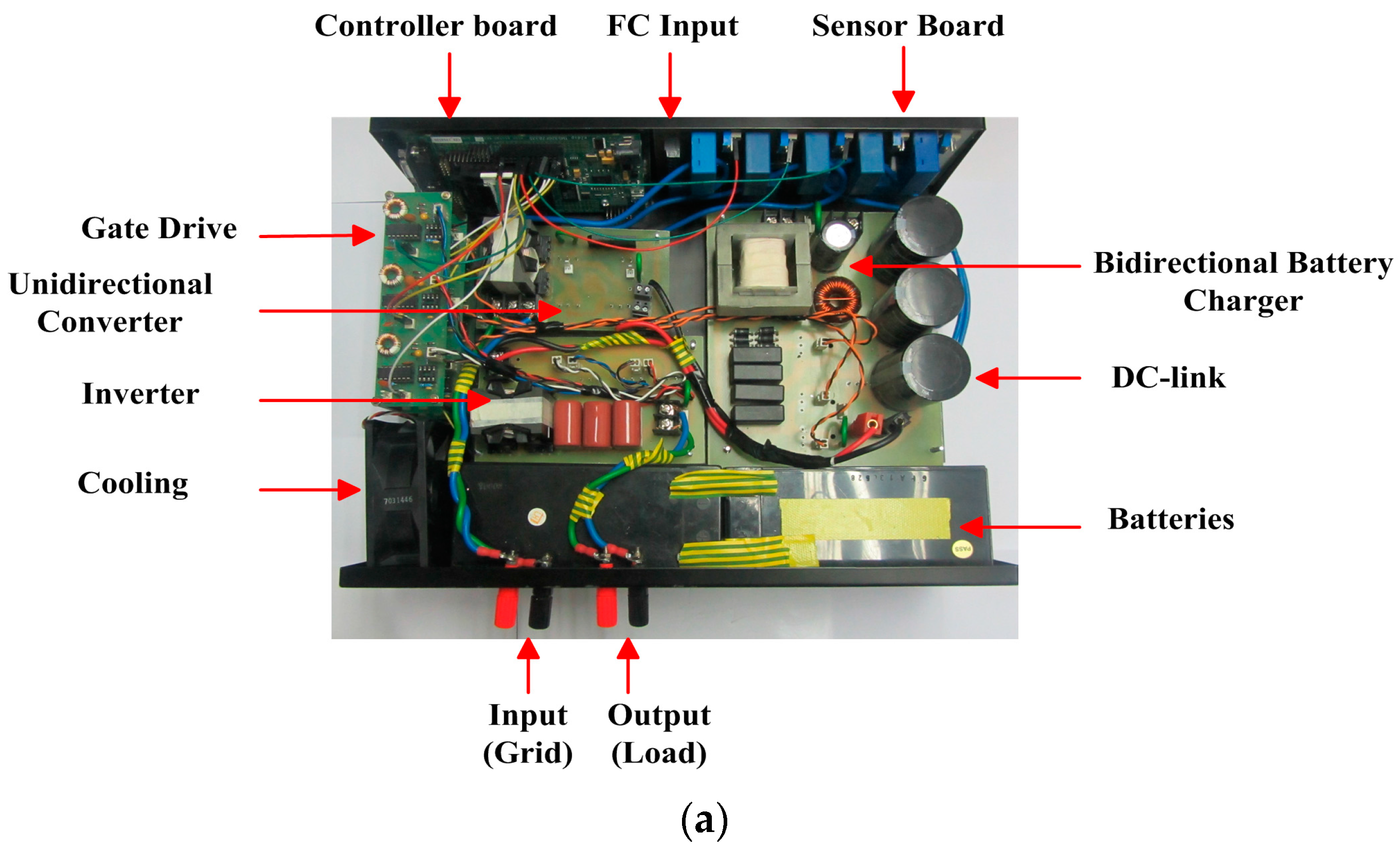
To validate the proposed line-interactive UPS system performance, a laboratory prototype has been implemented, as shown in Figure 10. The proposed system specifications are given in Table 5. The specifications of the battery charging/discharging unit and the inverter are presented in Table 6 and Table 7, respectively. The control architecture for the inverter and the battery charging/discharging unit has been implemented using DSP TMS320F28335. The backup storage system comprises a PEM fuel cell and a battery bank of 24 V (two batteries in series, each 12/15 Ah).
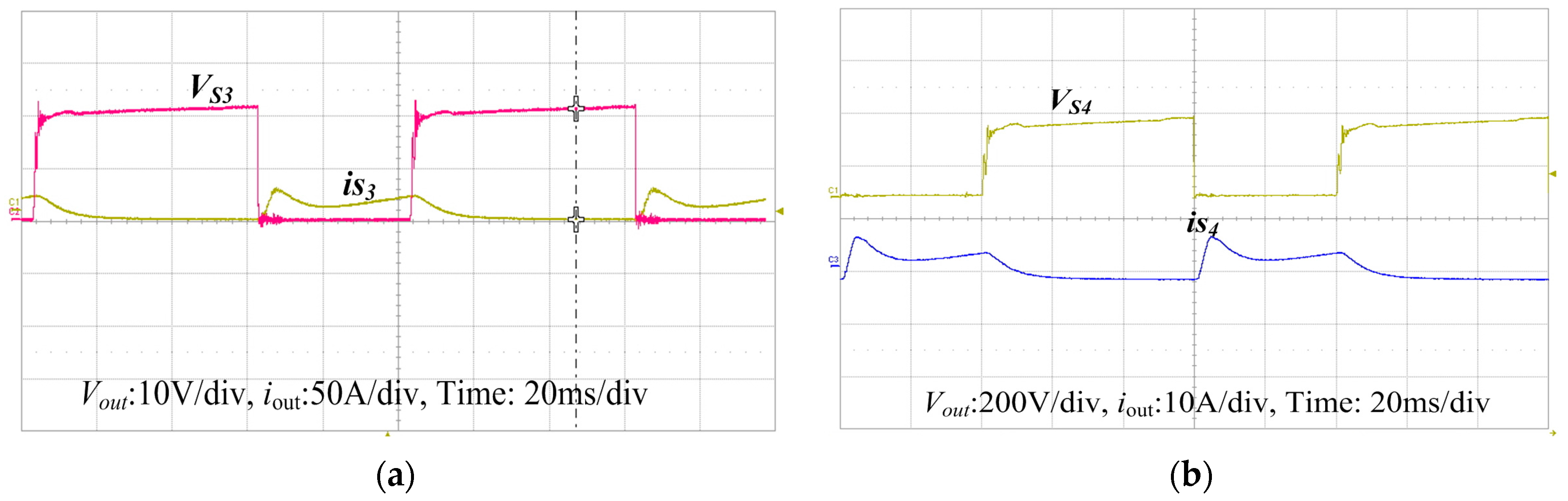
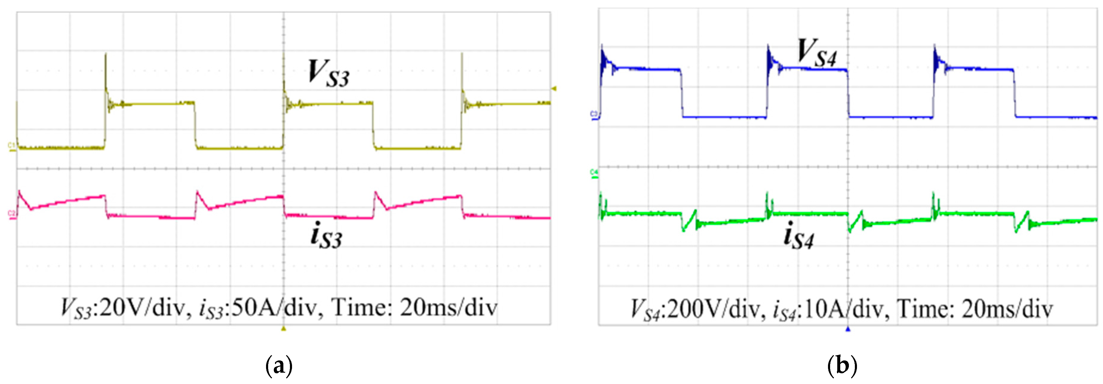
Figure 11 and Figure 12 show the drain to source voltage corresponding to switches S3 and S4 of the bidirectional converter (battery charger) for the buck and boost modes of operation, respectively. Both switches are operating under zero voltage switching (ZVS) conditions. For a linear load, the output voltage and current waveforms are presented in Figure 13a. As is clear from the figure, the waveforms are sinusoidal, with THD less than 1%. Moreover, the system is connected to the non-linear load designed according to the standard of IEC62040-3. The system exhibits a reasonable performance, with THD of 1.25% for the non-linear load, as presented in Figure 13b.
In case of grid power interruption, the system switches from grid mode to fuel cell/battery-powered mode. The battery charging/discharging unit operates in discharging mode and maintains a regulated DC link voltage for the inverter unless the fuel cell finishes the cold start. Then, the unidirectional DC–DC converter maintains the DC link voltage and feed power to the connected load through the inverter. The output voltage transient is very small, and the UPS system manages to provide uninterruptible power to the load, as depicted in Figure 14a. Additionally, the transition back from the fuel cell/battery-powered mode to the grid mode grid power restoration is presented in Figure 14b.
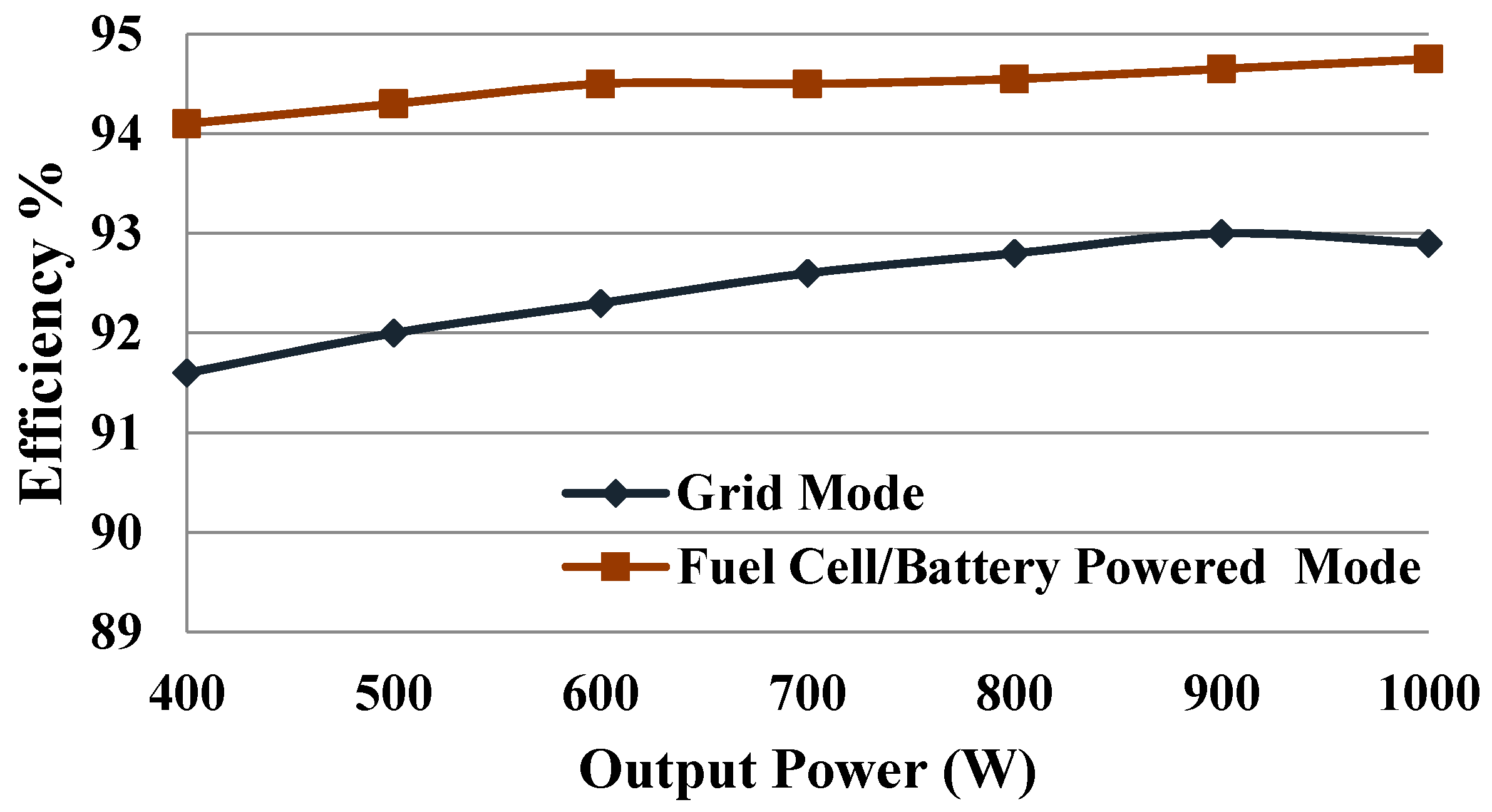
Figure 15 presents the efficiency curve with a maximum efficiency of around 94.8% during fuel cell/battery-powered mode and 93% during grid mode. The efficiency of the fuel cell/battery-powered mode is higher because fewer power stages (unidirectional DC–DC converter and inverter) are in operation during this mode. The overall efficiency of the proposed system is higher as compared to isolated topologies because of the transformerless operation of the circuit. Table 8 shows a comparison of the proposed system with other similar topologies. The proposed UPS system presents high efficiency with low total harmonic distortion and reduces the size of the system.
5. Conclusions
This paper presents a new circuit topology of a UPS system primarily fed by a fuel cell. Using fuel cells as an energy source increases the backup time of the UPS system. A unidirectional DC–DC converter is introduced, which steps up low fuel cell voltage to a high DC link voltage. Similarly, a bidirectional converter has been implemented for charging and discharging of the battery bank. The bidirectional converter has a high voltage conversion ratio, which significantly decreases the battery bank size. A novel control for inverter ensures regulated output voltage with low total harmonic distortion for both non-linear and step change in loads. The size, weight, and auxiliary battery bank size of the UPS are reduced, which improves the overall volume of the system. Moreover, extensive experiments have been carried out to validate the performance of the line-interactive UPS system.
Author Contributions
All authors have contributed to this work. Muhammad Iftikhar proposed the research idea and contributed to writing the paper. Muhammad Aamir performed the simulations and finalized the results. Asad Waqar, Naila, Fahad Bin Muslim and Imtiaz Alam contributed to the analysis of results. All authors have approved this paper
Conflicts of Interest
The authors declares no conflict of interest.
References
- Lahyani, A.; Venet, P.; Guermazi, A.; Troudi, A. Battery/supercapacitors combination in uninterruptible power supply (UPS). IEEE Trans. Power Electron. 2013, 28, 1509–1522. [Google Scholar] [CrossRef]
- Zhang, Y.; Yu, M.; Liu, F.; Kang, Y. Instantaneous current-sharing control strategy for parallel operation of UPS modules using virtual impedance. IEEE Trans. Power Electron. 2013, 28, 432–440. [Google Scholar] [CrossRef]
- Zhao, B.; Song, Q.; Liu, W.; Xiao, Y. Next-generation multi-functional modular intelligent UPS system for smart grid. IEEE Trans. Ind. Electron. 2013, 60, 3602–3618. [Google Scholar] [CrossRef]
- Branco, C.G.; Torrico-Bascope, R.P.; Cruz, C.M.; de A Lima, F. Proposal of three-phase high-frequency transformer isolation UPS topologies for distributed generation applications. IEEE Trans. Ind. Electron. 2013, 60, 1520–1531. [Google Scholar] [CrossRef]
- Sukumara, G.; Parthasarathy, A.; Shankar, V.R. Fuel cell based uninterrupted power sources. In Proceedings of the 1997 International Conference on Power Electronics and Drive Systems, Singapore, 26–29 May 1997. [Google Scholar]
- Latha, K.; Umamaheswari, B.; Chaitanya, K.; Rajalakshmi, N.; Dhathathreyan, K. A novel reconfigurable hybrid system for fuel cell system. Int. J. Hydrogen Energy 2015, 40, 14963–14977. [Google Scholar] [CrossRef]
- Boscaino, V.; Miceli, R.; Capponi, G.; Galluzzo, G.R. A review of fuel cell based hybrid power supply architectures and algorithms for household appliances. Int. J. Hydrogen Energy 2014, 39, 1195–1209. [Google Scholar] [CrossRef]
- Aamir, M.; Kalwar, K.A.; Mekhilef, S. Review: Uninterruptible Power Supply (UPS) system. Renew. Sustain. Energy Rev. 2016, 58, 1395–1410. [Google Scholar] [CrossRef]
- Gray, E.M.; Webb, C.; Andrews, J.; Shabani, B.; Tsai, P.; Chan, S. Hydrogen storage for off-grid power supply. Int. J. Hydrogen Energy 2011, 36, 654–663. [Google Scholar] [CrossRef]
- Tao, H.; Duarte, J.L.; Hendrix, M.A. Line-interactive UPS using a fuel cell as the primary source. IEEE Trans. Ind. Electron. 2008, 55, 3012–3021. [Google Scholar]
- Chang, H.-P.; Chou, C.-L.; Chen, Y.-S.; Hou, T.-I.; Weng, B.-P. The design and cost analysis of a portable PEMFC UPS system. Int. J. Hydrogen Energy 2007, 32, 316–322. [Google Scholar] [CrossRef]
- Choi, W.; Howze, J.W.; Enjeti, P. Fuel-cell powered uninterruptible power supply systems: Design considerations. J. Power Sources 2006, 157, 311–317. [Google Scholar] [CrossRef]
- Squadrito, G.; Giacoppo, G.; Barbera, O.; Urbani, F.; Passalacqua, E.; Borello, L.; Musso, A.; Rosso, I. Design and development of a 7kW polymer electrolyte membrane fuel cell stack for UPS application. Int. J. Hydrogen Energy 2010, 35, 9983–9989. [Google Scholar] [CrossRef]
- Lacko, R.; Drobnič, B.; Mori, M.; Sekavčnik, M.; Vidmar, M. Stand-alone renewable combined heat and power system with hydrogen technologies for household application. Energy 2014, 77, 164–170. [Google Scholar] [CrossRef]
- Isa, N.M.; Das, H.S.; Tan, C.W.; Yatim, A.; Lau, K.Y. A techno-economic assessment of a combined heat and power photovoltaic/fuel cell/battery energy system in Malaysia hospital. Energy 2016, 112, 75–90. [Google Scholar] [CrossRef]
- Bizon, N.; Radut, M.; Oproescu, M. Energy control strategies for the fuel cell hybrid power source under unknown load profile. Energy 2015, 86, 31–41. [Google Scholar] [CrossRef]
- Pukrushpan, J.T.; Stefanopoulou, A.G.; Peng, H. Control of Fuel Cell Power Systems: Principles, Modeling, Analysis and Feedback Design; Springer Science & Business Media: Berlin, Germany, 2004. [Google Scholar]
- Hegazy, O.; Barrero, R.; van Mierlo, J.; Lataire, P.; Omar, N.; Coosemans, T. An advanced power electronics interface for electric vehicles applications. IEEE Trans. Power Electron. 2013, 28, 5508–5521. [Google Scholar] [CrossRef]
- Wai, R.-J.; Lin, C.-Y. Active low-frequency ripple control for clean energy power-conditioning mechanism. IEEE Trans. Ind. Electron. 2010, 57, 3780–3792. [Google Scholar] [CrossRef]
- Itoh, J.-I.; Hayashi, F. Ripple current reduction of a fuel cell for a single-phase isolated converter using a DC active filter with a center tap. IEEE Trans. Power Electron. 2010, 25, 550–556. [Google Scholar] [CrossRef]
- Duan, R.Y.; Lee, J.D. High-efficiency bidirectional DC-DC converter with coupled inductor. IET Power Electron. 2012, 5, 115–123. [Google Scholar] [CrossRef]
- Zargari, N.; Ziogas, P.; Joos, G. A two switch high performance current regulated DC/AC converter module. IEEE Trans. Ind. Appl. 1995, 31, 583–589. [Google Scholar] [CrossRef]
- Maciel, S.R.; de Freitas, C.L.; Coelho, A.E.A.; Vieira, J.B.; de Freitas, L.G.G. Front-end converter with integrated PFC and DC–DC functions for a fuel cell UPS with DSP-based Control. IEEE Trans. Power Electron. 2015, 30, 4175–4188. [Google Scholar] [CrossRef]
- Jang, M.; Ciobotaru, M.; Agelidis, V.G. A single-stage fuel cell energy system based on a buck—Boost inverter with a backup energy storage unit. IEEE Trans. Power Electron. 2012, 27, 2825–2834. [Google Scholar] [CrossRef]
Figure 1.
Proposed circuit diagram of line-interactive transformerless UPS system.

Figure 2.
Operational modes of the line-interactive UPS system.
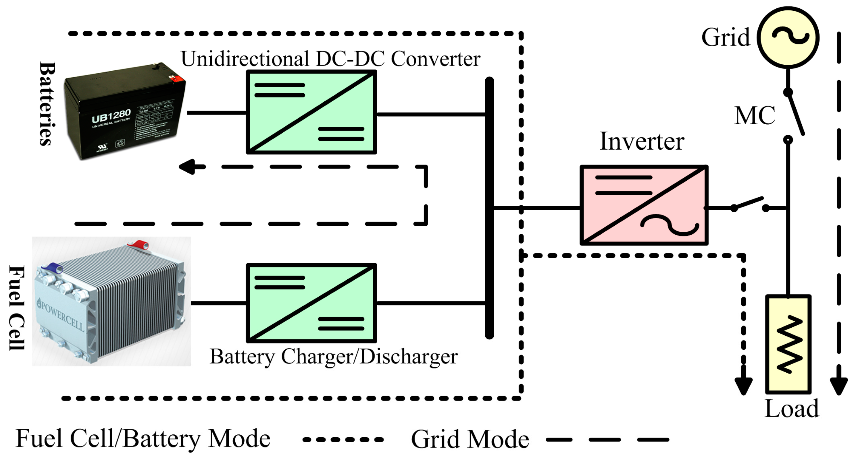
Figure 3.
Equivalent electric model of fuel cell.

Figure 4.
Thevenin’s model of a lead acid battery.

Figure 5.
Characteristic waveforms of a bidirectional DC–DC converter.
Figure 6.
Topological stages of battery charger/discharger during buck mode of operation: (a) Mode 1; (b) Mode 2; (c) Mode 3; (d) Mode 4; (e) Mode 5.
Figure 6.
Topological stages of battery charger/discharger during buck mode of operation: (a) Mode 1; (b) Mode 2; (c) Mode 3; (d) Mode 4; (e) Mode 5.

Figure 7.
Characteristic waveforms during boost mode.

Figure 8.
Topological stages during boost mode: (a) Mode 1; (b) Mode 2; (c) Mode 3; (d) Mode 4; (e) Mode 5; (f) Mode 6.
Figure 8.
Topological stages during boost mode: (a) Mode 1; (b) Mode 2; (c) Mode 3; (d) Mode 4; (e) Mode 5; (f) Mode 6.
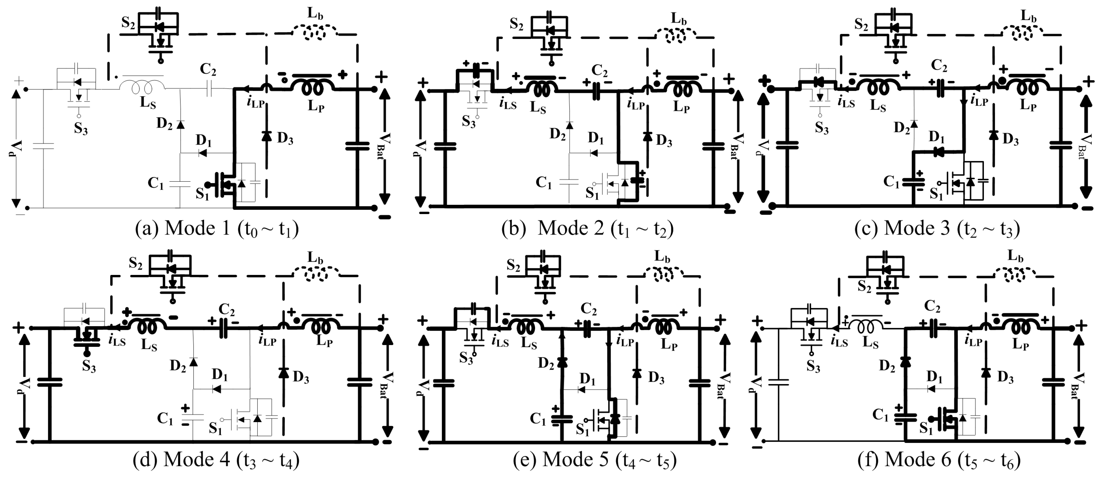
Figure 9.
Control circuitry for the proposed line-interactive UPS system.
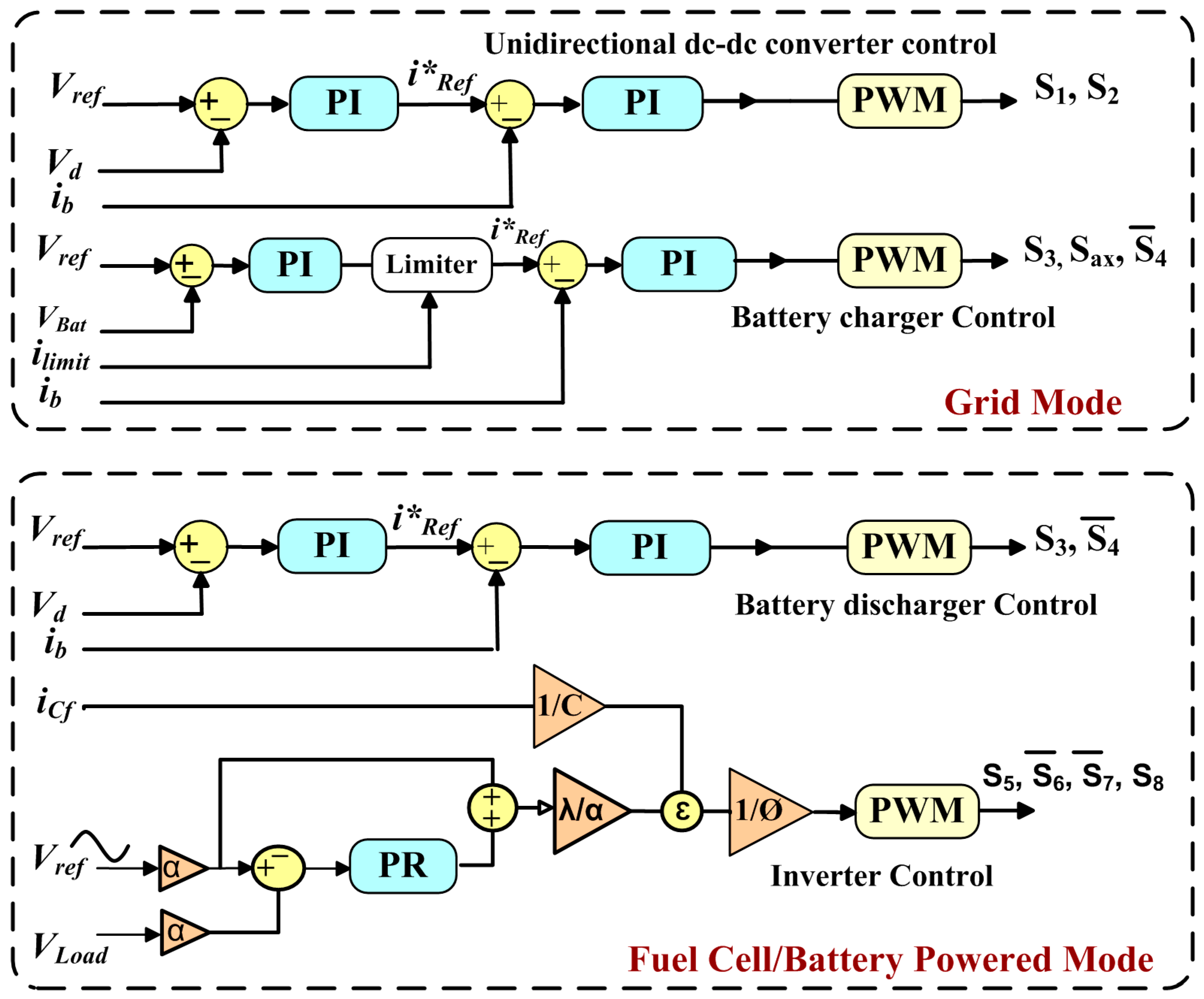
Figure 10.
Experimental prototype of the proposed line-interactive UPS system: (a) Prototype Image; (b) Experimental setup.
Figure 10.
Experimental prototype of the proposed line-interactive UPS system: (a) Prototype Image; (b) Experimental setup.

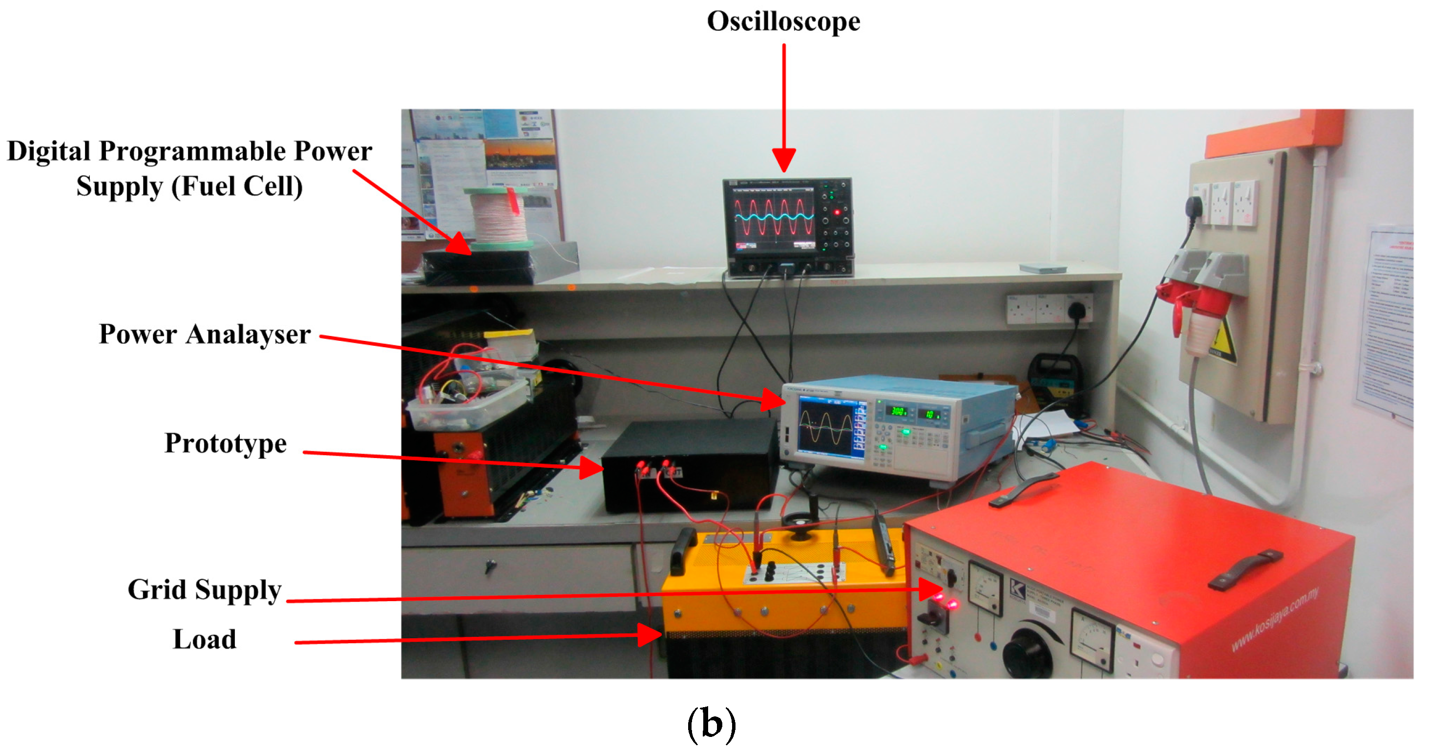
Figure 11.
Drain to source voltage and current of switches during battery charging (buck mode): (a) Switch S3; (b) Switch S4.
Figure 11.
Drain to source voltage and current of switches during battery charging (buck mode): (a) Switch S3; (b) Switch S4.

Figure 12.
Drain to source voltage and current of switches S3 and S4 during battery discharging (boost mode): (a) Switch S3; (b) Switch S4
Figure 12.
Drain to source voltage and current of switches S3 and S4 during battery discharging (boost mode): (a) Switch S3; (b) Switch S4

Figure 13.
Output voltage and current waveform: (a) Linear load; (b) non-linear load.
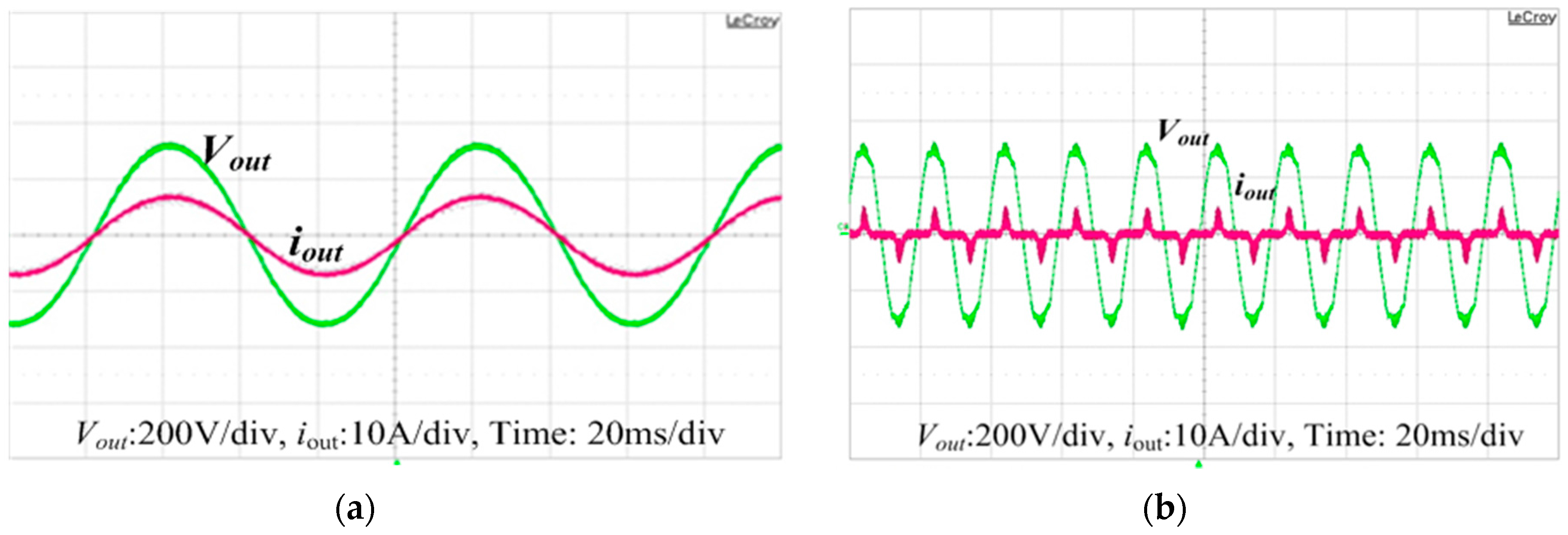
Figure 14.
Output voltage and current waveform. (a) Transition from grid to fuel cell/battery mode; (b) transition from fuel cell/battery to grid mode.
Figure 14.
Output voltage and current waveform. (a) Transition from grid to fuel cell/battery mode; (b) transition from fuel cell/battery to grid mode.
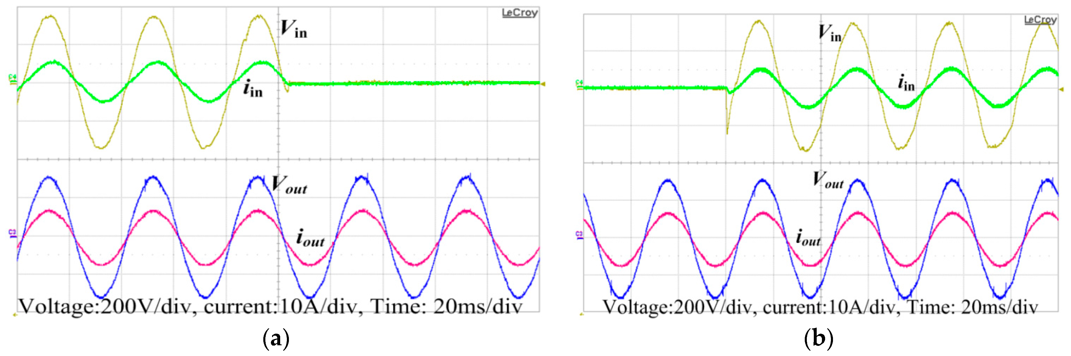
Figure 15.
Efficiency graph in grid and fuel cell/battery-powered modes.

Table 1.
PEMFC specifications.
| Parameters | Value |
|---|---|
| Rated Power | 1000 W |
| Rated Performance | 28.8 V @ 35 A |
| No. of cells | 48 |
| Max. Stack Temp | 338 K |
| Oxygen Pressure | 0.26 Bar |
| Hydrogen Pressure | 0.45–0.55 Bar |
Table 2.
Battery specifications.
| Parameters | Value |
|---|---|
| Rated Capacity | 21 Ah |
| Nominal Voltage | 24 V |
| Min. Voltage | 16 V |
| Max. Charging Current limit | 9.9 A |
| Max. Discharge Current | 105 A |
| Initial SoC | 70% |
| Internal Resistance | 8 mΩ |
Table 3.
Comparison of proposed bidirectional converter.
| Features | [19] | [22] | [21] | [20] | Proposed Topology |
|---|---|---|---|---|---|
| Switches | 4 | 5 | 4 | 4 | 3 |
| Auxiliary Capacitors | 2 | 3 | 2 | 2 | 2 |
| Coupled-Inductor | 1 | 1 | 1 | 0 | 1 |
| Auxiliary Inductor | 1 | 0 | 0 | 1 | 1 |
| MBOOST | |||||
| MBUCK | |||||
| Efficiency | 97% | 96% | 95% | 94% | 96% |
| Size | Large | Large | Medium | Medium | Small |
| Estimated Cost (USD) | ~130 | ~172 | ~118 | ~136 | ~116 |
Table 4.
Inverter control parameters.
| Sr. No | Parameters | Value |
|---|---|---|
| 1 | KP | 2.5 |
| 2 | KR | 30 |
| 3 | λ | 20,000 |
| 4 | Φ | 126,830 |
| 5 | Vm | 8 V |
| 6 | α | 0.02227 |
| 7 | Vref | 220 V |
Table 5.
Specifications of the proposed UPS system.
| Parameters | Symbol | Value |
|---|---|---|
| Input Voltage | Vin | 220 V |
| Output Voltage | Vout | 220 V |
| Grid Frequency | fr | 50 Hz |
| Output Frequency | fo | 50 Hz |
| Number of Batteries | Vb | 2 (12 V/15 Ah) |
| PEM Fuel Cell | VFC | 30 @ 35 A |
| Maximum Output Power | PO, max | 1 kVA |
| DC link Voltage | Vd | 360 V |
Table 6.
Specifications of battery charger/discharger.
| Parameters | Symbol | Value |
|---|---|---|
| DC link Voltage | Vd | 360 V |
| Battery Bank Voltage | Vb | 24 V |
| Switching Frequency | fs | 30,000 Hz |
| Coupled Inductor | LP,LS | Turns ratio N = 4; Lm = 107uH; PQ-5050 core; |
| Inductor | Lb | 300 uH |
| Capacitor | Cb1, Cb2, Cd | Cb1, Cb2 = 2 × 2.2 uF (ceramic), Cd = 1900 uF |
| Switches | S3,S4, Sax | IPW60R045CP MOSFET |
| Diodes | Db1, Db2, Db3 | Ultrafast Recovery UF5408 |
Table 7.
Design parameters of the inverter.
| Parameters | Symbol | Value |
|---|---|---|
| Switching Frequency | fs | 20,000 Hz |
| Switches | S5~S8 | SPP11N60C3 |
| Output Filter Inductor | Lf | 840 µH |
| Output Filter Capacitor | Cf | 6.6 µF |
| Cutoff Frequency | fcut | 1700 Hz |
Table 8.
Comparison of the proposed UPS system.
| Properties | Efficiency | Power Ratings | System Specifications | Output THD | Size & Weight | |
|---|---|---|---|---|---|---|
| UPS Topologies | ||||||
| Front-End Converter With Integrated PFC and DC–DC Functions for a Fuel Cell UPS With DSP-Based Control [23] | 94% | 500 W | 127 V | 7%< | Medium | |
| A Single-Stage Fuel Cell Energy System Based on a Buck–Boost Inverter with a Backup Energy Storage Unit [24] | 82% | 500 W | 220 V | 2% | Medium | |
| Line-Interactive UPS Using a Fuel Cell as the Primary Source [10] | - | 3.2 KW | 220 V | 5%< | Large | |
| Proposed System | 94.8% | 1 KW | 220 V | 1.25 | Small | |
© 2018 by the authors. Licensee MDPI, Basel, Switzerland. This article is an open access article distributed under the terms and conditions of the Creative Commons Attribution (CC BY) license (http://creativecommons.org/licenses/by/4.0/).
Share and Cite
MDPI and ACS Style
Iftikhar, M.; Aamir, M.; Waqar, A.; Naila; Muslim, F.B.; Alam, I. Line-Interactive Transformerless Uninterruptible Power Supply (UPS) with a Fuel Cell as the Primary Source. Energies 2018, 11, 542. https://doi.org/10.3390/en11030542
AMA Style
Iftikhar M, Aamir M, Waqar A, Naila, Muslim FB, Alam I. Line-Interactive Transformerless Uninterruptible Power Supply (UPS) with a Fuel Cell as the Primary Source. Energies. 2018; 11(3):542. https://doi.org/10.3390/en11030542
Chicago/Turabian StyleIftikhar, Muhammad, Muhammad Aamir, Asad Waqar, Naila, Fahad Bin Muslim, and Imtiaz Alam. 2018. "Line-Interactive Transformerless Uninterruptible Power Supply (UPS) with a Fuel Cell as the Primary Source" Energies 11, no. 3: 542. https://doi.org/10.3390/en11030542
Note that from the first issue of 2016, this journal uses article numbers instead of page numbers. See further details here.