Annual Prediction Output of an RADTIRC-PV Module


 ,
,  , and
, and
Abstract
:
1. Introduction
“..(1) to ensure universal access to affordable, reliable and modern energy services; (2) to increase substantially the share of renewable energy in the global energy mix; (3) to double the global rate of improvement in energy efficiency; (4) to enhance international cooperation to facilitate access to clean energy research and technology, including renewable energy, energy efficiency and advanced and cleaner fossil-fuel technology, and to promote investment in energy infrastructure and clean energy technology, and (5) to expand infrastructure and upgrade technology for supplying modern and sustainable energy services for all in developing countries, in particular in the least developed countries, small island developing states, and land-locked developing countries, in accordance with their respective programs of support.”
2. RADTIRC—What Has Been Achieved
3. Key Parameters to Calculate the Annual Electrical Output of an RADTIRC-PV Module
3.1. Tilt Angle of the Modules
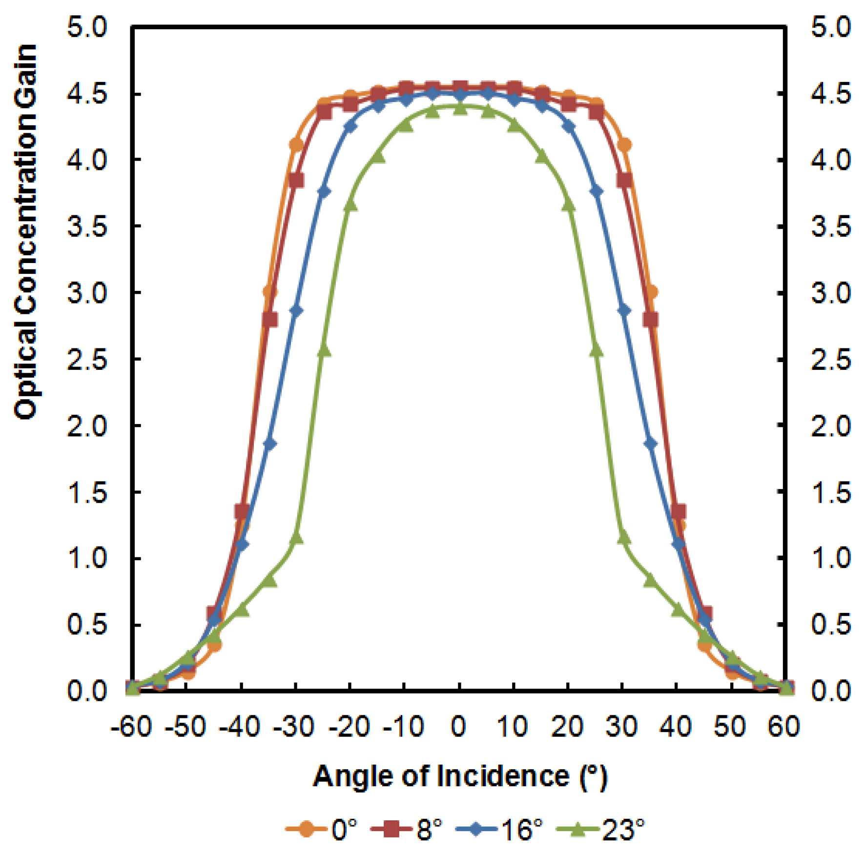
3.2. Optical Concentration Gain of the RADTIRC on Tilted Surface
3.3. Irradiation Data
4. Results and Discussion
5. Conclusions
Acknowledgments
Author Contributions
Conflicts of Interest
References
- United Nations. Goal 7: Ensure Access to Affordable, Reliable, Sustainable and Modern Energy for All. Available online: http://www.un.org/sustainabledevelopment/energy/ (accessed on 7 December 2016).
- United Nations. Sustainable Development Knowledge Platform. Available online: https://sustainabledevelopment.un.org/sdg7 (accessed on 7 December 2016).
- IRENA. Sustainable Energy for All and SDG 7 in Focus. Available online: https://irenanewsroom.org/2015/09/30/sustainable-energy-for-all-and-sdg-7-in-focus/ (accessed on 7 December 2016).
- IPCC. Climate Change 2014: Mitigation of Climate Change. Contribution of Working Group III to the Fifth Assessment Report of the Intergovernmental Panel on Climate Change; Cambridge University Press: Cambridge, UK; New York, NY, USA, 2014. [Google Scholar]
- Chen, C.J. Physics of Solar Energy; John Wiley & Sons: New Jersey, NJ, USA, 2011; ISBN 9781118044599. [Google Scholar]
- Lewis, N.S.; Nocera, D.G. Powering the planet: chemical challenges in solar energy utilization. Proc. Natl. Acad. Sci. USA 2006, 103, 15729–15735. [Google Scholar] [CrossRef] [PubMed]
- International Energy Agency (IEA). Energy Technology Perspectives 2014: Executive Summary; IEA: Paris, France, 2014. [Google Scholar]
- Luque, A.; Hegedus, S. Handbook of Photovoltaic Science and Engineering, 2nd ed.; John Wiley and Sons, Ltd.: New Jersey, NJ, USA, 2010. [Google Scholar]
- Renewable Energy Policy Network for the 21st Century (REN 21). Renewables 2017: Global Status Report; REN 21: Paris, France, 2017. [Google Scholar]
- International Energy Agency-Photovoltaic Power System Programme (IEA-PVPS). Trends 2016 in Photovoltaic Applications; IEA-PVPS: St. Ursen, Switzerland, 2016. [Google Scholar]
- International Renewable Energy Agency (IRENA). Renewable Energy Technologies: Cost Analysis Series—Solar Photovoltaics; IRENA: Abu Dhabi, UAE, 2012. [Google Scholar]
- Lo, C.-C.; Wang, C.-H.; Huang, C.-C. The national innovation system in the Taiwanese photovoltaic industry: A multiple stakeholder perspective. Technol. Forecast. Soc. Chang. 2013, 80, 893–906. [Google Scholar] [CrossRef]
- Goodrich, A.; Hacke, P.; Wang, Q.; Sopori, B.; Margolis, R.; James, T.L.; Woodhouse, M. A wafer-based monocrystalline silicon photovoltaics road map: Utilizing known technology improvement opportunities for further reductions in manufacturing costs. Sol. Energy Mater. Sol. Cells 2013, 114, 110–135. [Google Scholar] [CrossRef]
- Munir, A.B.; Muhammad-Sukki, F.; Bani, N.A. Renewables: Solar energy needs focus. Nature 2016, 529, 466. [Google Scholar] [CrossRef] [PubMed]
- Swanson, R.M. Photovoltaic Concentrators. In Handbook of Photovoltaic Science and Engineering; John Wiley & Sons, Ltd.: New Jersey, NJ, USA, 2003; pp. 449–503. ISBN 9780470014004. [Google Scholar]
- Muhammad-Sukki, F.; Ramirez-Iniguez, R.; Mcmeekin, S.G.; Stewart, B.G.; Clive, B. Solar concentrators. Int. J. Appl. Sci. 2010, 1, 1–15. [Google Scholar]
- Sarmah, N. Design and Performance Evaluation of a Low Concentrating Line-Axis Dielectric Photovoltaic System. Ph.D. Thesis, Heriot-Watt University, Edinburgh, UK, 2012. [Google Scholar]
- Welford, W.T.; Winston, R. High Collection Nonimaging Optics; Academic Press: Cambridge, MA, USA, 1989; ISBN 9780127428857. [Google Scholar]
- Chaves, J. Introduction to Nonimaging Optics; CRC Press: Boca Raton, FL, USA, 2008; ISBN 978-1420054293. [Google Scholar]
- Winston, R.; Miñano, J.C.; Benítez, P.; Shatz, N.; Bortz, J.C. Nonimaging Optics; Academic Press: Cambridge, MA, USA, 2005; ISBN 9780127597515. [Google Scholar]
- Ramirez-Iniguez, R.; Idrus, S.M.; Sun, Z. Optical Wireless Communications: IR for Wireless Connectivity; AUERBACH Publication: Boca Raton, FL, USA, 2008; ISBN 978-0849372094. [Google Scholar]
- Rabl, A. Comparison of solar concentrators. Sol. Energy 1976, 18, 93–111. [Google Scholar] [CrossRef]
- Philipps, S.P.; Bett, A.W.; Horowitz, K.; Kurtz, S. Current Status of Concentrator Photovoltaic (CPV) Technology; National Renewable Energy Laboratory (NREL): Lakewood, CO, USA, 2016. [Google Scholar]
- Baig, H.; Mallick, T.K. Challenges and opportunities in concentrating photovoltaic research. Mod. Energy Rev. 2011, 3, 18–26. [Google Scholar]
- Chemisana, D. Building Integrated Concentrating Photovoltaics: A review. Renew. Sustain. Energy Rev. 2011, 15, 603–611. [Google Scholar] [CrossRef]
- Norton, B.; Eames, P.C.; Mallick, T.K.; Huang, M.J.; McCormack, S.J.; Mondol, J.D.; Yohanis, Y.G. Enhancing the performance of building integrated photovoltaics. Sol. Energy 2011, 85, 1629–1664. [Google Scholar] [CrossRef]
- Chemisana, D.; Zacharopoulos, A. Building-Integration of High-Concentration Photovoltaic Systems. In High Concentrator Photovoltaics; Springer: Cham, Switzerland, 2015; pp. 353–376. [Google Scholar]
- Abu-Bakar, S.H.; Muhammad-Sukki, F.; Freier, D.; Ramirez-Iniguez, R.; Mallick, T.K.; Munir, A.B.; Mohd Yasin, S.H.; Abubakar Mas’ud, A.; Md Yunus, N. Optimisation of the performance of a novel rotationally asymmetrical optical concentrator design for building integrated photovoltaic system. Energy 2015, 90, 1033–1045. [Google Scholar] [CrossRef]
- Sick, F.; Erge, T. Photovoltaics in Buildings: A Design Handbook for Architects and Engineers, 1st ed.; Routledge: Abingdon, UK, 1996. [Google Scholar]
- Lowder, T. The Challenges of Building-Integrated Photovoltaics. Available online: www.renewableenergyworld.com/articles/2012/05/the-challenges-building-integrated-photovoltaics.html (accessed on 16 April 2016).
- James, T.; Goodrich, A.; Woodhouse, M.; Margolis, R.; Ong, S. Building-Integrated Photovoltaics (BIPV) in the Residential Sector: An Analysis of Installed Rooftop System Prices; National Renewable Energy Laboratory (NREL): Lakewood, CO, USA, 2011. [Google Scholar]
- GTM Research. Building-Integrated Photovoltaics: An Emerging Market; GTM Research: Boston, MA, USA, 2010. [Google Scholar]
- Freier, D.; Muhammad-Sukki, F.; Abu-Bakar, S.H.; Ramirez-Iniguez, R.; Abubakar Mas’ud, A.; Albarracín, R.; Ardila-Rey, J.A.; Munir, A.B.; Mohd Yasin, S.H.; Bani, N.A. Software simulation and experimental characterisation of a rotationally asymmetrical concentrator under direct and diffuse solar radiation. Energy Convers. Manag. 2016, 122, 223–238. [Google Scholar] [CrossRef] [Green Version]
- Sellami, N. Design and Characterisation of a Novel Translucent Solar Concentrator. Ph.D. Thesis, Heriot-Watt University, Edinburgh, UK, 2013. [Google Scholar]
- Polysolar. Guide to BIPV; Polysolar Limited: Cambridge, UK, 2015. [Google Scholar]
- Muhammad-Sukki, F.; Ramirez-Iniguez, R.; McMeekin, S.G.; Stewart, B.G.; Clive, B. Optimisation of concentrator in the Solar Photonic Optoelectronic Transformer: Comparison of geometrical performance and cost of implementation. Renew. Energy Power Qual. J. 2011, 9, 1–6. [Google Scholar] [CrossRef]
- ICC Evaluation Service. Acceptance Criteria for Building-Integrated Photovoltaic (BIPV) Roof Covering Systems; ICC Evaluation Service: Brea, CA, USA, 2011. [Google Scholar]
- Muhammad-Sukki, F.; Abu-Bakar, S.H.; Ramirez-Iniguez, R.; McMeekin, S.G.; Stewart, B.G.; Sarmah, N.; Mallick, T.K.; Munir, A.B.; Mohd Yasin, S.H.; Abdul Rahim, R. Mirror symmetrical dielectric totally internally reflecting concentrator for building integrated photovoltaic systems. Appl. Energy 2014, 113, 32–40. [Google Scholar] [CrossRef]
- Abu-Bakar, S.H.; Muhammad-Sukki, F.; Freier, D.; Ramirez-Iniguez, R.; Mallick, T.K.; Munir, A.B.; Mohd Yasin, S.H.; Abubakar Mas’ud, A.; Md Yunus, N. Performance analysis of a novel rotationally asymmetrical compound parabolic concentrator. Appl. Energy 2015, 154, 221–231. [Google Scholar] [CrossRef]
- Abu-Bakar, S.H.; Muhammad-Sukki, F.; Ramirez-Iniguez, R.; Freier, D.; Mallick, T.K.; Munir, A.B.; Mohd Yasin, S.H.; Abubakar Mas’ud, A.; Bani, N.A. Novel optical concentrator technology for building integrated photovoltaic systems. In Proceedings of the 2016 World Conference on Innovation, Engineering, and Technology (IET 2016), Sapporo, Japan, 24–26 June 2016; pp. 355–365. [Google Scholar]
- Ramirez-Iniguez, R.; Deciga-Gusi, J.; Freier, D.; Abu-Bakar, S.H.; Muhammad-Sukki, F. Experimental evaluation of a solar window incorporating rotationally asymmetrical compound parabolic concentrators (RACPC). Energy Proced. 2017, 130, 102–107. [Google Scholar] [CrossRef]
- Singh, H.; Sabry, M.; Redpath, D.A. Experimental investigations into low concentrating line axis solar concentrators for CPV applications. Sol. Energy 2016, 136, 421–427. [Google Scholar] [CrossRef]
- Bojić, M.; Marjanović, N.; Miletić, I.; Bojić, L. Comparison of optical performances of sea-shell trough solar concentrators. Energy Build. 2015, 98, 144–150. [Google Scholar] [CrossRef]
- Wu, Y.; Connelly, K.; Liu, Y.; Gu, X.; Gao, Y.; Chen, G.Z. Smart solar concentrators for building integrated photovoltaic façades. Sol. Energy 2016, 133, 111–118. [Google Scholar] [CrossRef]
- Meng, X.; Sellami, N.; Knox, A.R.; Montecucco, A.; Siviter, J.; Mullen, P.; Ashraf, A.; Samarelli, A.; Llin, L.F.; Paul, D.J.; et al. A novel absorptive/reflective solar concentrator for heat and electricity generation: An optical and thermal analysis. Energy Convers. Manag. 2016, 114, 142–153. [Google Scholar] [CrossRef]
- Slooff, L.H.; Bende, E.E.; Burgers, A.R.; Budel, T.; Pravettoni, M.; Kenny, R.P.; Dunlop, E.D.; Büchtemann, A. A luminescent solar concentrator with 7.1% power conversion efficiency. Phys. Status Solidi Rapid Res. Lett. 2008, 2, 257–259. [Google Scholar] [CrossRef]
- Lo, C.K.; Lim, Y.S.; Tan, S.G.; Rahman, F.A. A new hybrid algorithm using thermodynamic and backward ray-tracing approaches for modeling luminescent solar concentrators. Energies 2010, 3, 1831–1860. [Google Scholar] [CrossRef]
- Pei, G.; Li, G.; Su, Y.; Ji, J.; Riffat, S.; Zheng, H. Preliminary ray tracing and experimental study on the effect of mirror coating on the optical efficiency of a solid dielectric compound parabolic concentrator. Energies 2012, 5, 3627–3639. [Google Scholar] [CrossRef]
- Vu, N.; Shin, S. A concentrator photovoltaic system based on a combination of prism-compound parabolic concentrators. Energies 2016, 9, 645. [Google Scholar] [CrossRef]
- Tien, N.; Shin, S. A novel concentrator photovoltaic (CPV) system with the improvement of irradiance uniformity and the capturing of diffuse solar radiation. Appl. Sci. 2016, 6, 251. [Google Scholar] [CrossRef]
- Liu, X.; Wu, Y.; Hou, X.; Liu, H. Investigation of the optical performance of a novel planar static PV concentrator with Lambertian rear reflectors. Buildings 2017, 7, 88. [Google Scholar] [CrossRef]
- Meng, X.-L.; Xia, X.-L.; Dai, G.-L.; Guene Lougou, B.; Wu, S.-L. A vector based freeform approach for reflecting concentrator of solar energy. Sol. Energy 2017, 153, 691–699. [Google Scholar] [CrossRef]
- Selvaraj, P.; Baig, H.; Mallick, T.K.; Siviter, J.; Montecucco, A.; Li, W.; Paul, M.; Sweet, T.; Gao, M.; Knox, A.R.; et al. Enhancing the efficiency of transparent dye-sensitized solar cells using concentrated light. Sol. Energy Mater. Sol. Cells 2018, 175, 29–34. [Google Scholar] [CrossRef]
- van Dijk, L.; Marcus, E.A.P.; Oostra, A.J.; Schropp, R.E.I.; Di Vece, M. 3D-printed concentrator arrays for external light trapping on thin film solar cells. Sol. Energy Mater. Sol. Cells 2015, 139, 19–26. [Google Scholar] [CrossRef]
- Price, J.S.; Sheng, X.; Meulblok, B.M.; Rogers, J.A.; Giebink, N.C. Wide-angle planar microtracking for quasi-static microcell concentrating photovoltaics. Nat. Commun. 2015, 6, 6223. [Google Scholar] [CrossRef] [PubMed]
- Abu-Bakar, S.H.; Muhammad-Sukki, F.; Freier, D.; Ramirez-Iniguez, R.; Mallick, T.K.; Munir, A.B.; Mohd Yasin, S.H.; Abubakar Mas’ud, A.; Abu-Bakar, S.S.; Bani, N.A.; et al. Potential of implementing the low concentration photovoltaic systems in the United Kingdom. Int. J. Electr. Comput. Eng. 2017, 7, 1398–1405. [Google Scholar] [CrossRef]
- Sarmah, N.; Richards, B.S.; Mallick, T.K. Design, development and indoor performance analysis of a low concentrating dielectric photovoltaic module. Sol. Energy 2014, 103, 390–401. [Google Scholar] [CrossRef]
- Ramirez-Iniguez, R.; Muhammad-Sukki, F.; McMeekin, S.G.; Stewart, B.G. Optical element. U.S. Patent 20140345689A1, 27 November 2014. [Google Scholar]
- Muhammad-Sukki, F.; Abu-Bakar, S.H.; Ramirez-Iniguez, R.; McMeekin, S.G.; Stewart, B.G.; Munir, A.B.; Mohd Yasin, S.H.; Abdul Rahim, R. Performance analysis of a mirror symmetrical dielectric totally internally reflecting concentrator for building integrated photovoltaic systems. Appl. Energy 2013, 111, 288–299. [Google Scholar] [CrossRef]
- Freier, D.; Muhammad-Sukki, F.; Abu-bakar, S.H.; Ramirez-Iniguez, R.; Munir, A.B.; Mohd Yasin, S.H.; Abubakar Mas’ud, A.; Bani, N.A. Effect of Diffuse Radiation on the Performance of a Rotationally Asymmetrical Optical Concentrator. In Proceedings of the 2016 IEEE 6th International Conference on Photonics (ICP2016), Kuching, Sarawak,Malaysia, 14–17 March 2016; IEEE: New Jersey, NJ, USA, 2016; pp. 71–73. [Google Scholar]
- Abu-Bakar, S.H.; Muhammad-Sukki, F.; Freier, D.; Ramirez-Iniguez, R.; Mallick, T.K.; Munir, A.B.; Mohd Yasin, S.H.; Abubakar Mas’ud, A.; Bani, N.A. Performance analysis of a solar window incorporating a novel rotationally asymmetrical concentrator. Energy 2016, 99, 181–192. [Google Scholar] [CrossRef]
- Lamnatou, C.; Baig, H.; Chemisana, D.; Mallick, T.K. Dielectric-based 3D building-integrated concentrating photovoltaic modules: An environmental life-cycle assessment. Energy Build. 2017, 138, 514–525. [Google Scholar] [CrossRef]
- Baig, H.; Fernández, E.F.; Mallick, T.K. Influence of spectrum and latitude on the annual optical performance of a dielectric based BICPV system. Sol. Energy 2016, 124, 268–277. [Google Scholar] [CrossRef]
- Li, W.; Paul, M.C.; Rolley, M.; Sweet, T.; Gao, M.; Baig, H.; Fernandez, E.F.; Mallick, T.K.; Montecucco, A.; Siviter, J.; et al. A coupled optical-thermal-electrical model to predict the performance of hybrid PV/T-CCPC roof-top systems. Renew. Energy 2017, 112, 166–186. [Google Scholar] [CrossRef]
- ECN. Architects Just Want to Develop Attractive Buildings. Available online: https://www.ecn.nl/nl/nieuws/newsletter-en/2009/june-2009/solar-energy-architecture/ (accessed on 10 November 2017).
- Boxwell, M. Solar Electricity Handbook; Green Stream Publishing: London, UK, 2015; ISBN 190767053X. [Google Scholar]
- Quaschning, V. Understanding Renewable Energy Systems, 1st ed.; Earthscan: Bath, UK, 2005; ISBN 1-84407-128-6. [Google Scholar]
- Joint Research Centre and Institue for Energy and Transport. Photovoltaic Geographical Information System (PVGIS). Available online: http://re.jrc.ec.europa.eu/pvgis/ (accessed on 28 October 2015).
- University of Oregon. Sun Path Chart Program. Available online: http://solardat.uoregon.edu/SunChartProgram.html (accessed on 16 November 2017).
- Weniger, J. Dimensionierung und Netzintegration von PV-Speichersystemen. Master’s Thesis, University of Applied Sciences, Berlin, Germany, 2013. [Google Scholar]
- Klucher, T.M. Evaluation of models to predict insolation on tilted surfaces. Sol. Energy 1979, 23, 111–114. [Google Scholar] [CrossRef]
- Baig, H.; Heasman, K.C.; Mallick, T.K. Non-uniform illumination in concentrating solar cells. Renew. Sustain. Energy Rev. 2012, 16, 5890–5909. [Google Scholar] [CrossRef]
- Bowden, S.; Wenham, S.R.; Coffey, P.; Dickinson, M.; Green, M.A. High efficiency photovoltaic roof tile with static concentrator. Proceedings of the Conference Record of the Twenty Third IEEE Photovoltaic Specialists Conference—1993, (Cat. No.93CH3283-9), Louisville, KY, USA, 10–14 May 1993; IEEE: New Jersey, NJ, USA, 1993; pp. 1068–1072. [Google Scholar]


| Advantages | Disadvantages |
|---|---|
| Cheaper panel cost due to the reduction in the use of expensive PV material, as long as the cost of the concentrator is cheaper than the cost of displaced PV material [28]. | The concentrator requires precise machining during the manufacturing process to ensure optimum performance. This could increase the cost of the panel. |
| For building integration, other cost saving potential include: (i) eliminating the additional cost of infrastructure to mount the panels, which is required for ground mounted installation; (ii) eliminating the cabling cost to connect the installation to the grid can be reduced because almost all buildings are connected to the national grid, unlike the installation in isolated PV farms; and (iii) reducing the building material cost can be reduced since the panel replaces part of the building structure (e.g., roof, façade and window) [29]. | A BICPV system is could also be more expensive than a standard mass-marketed roof/façade-mounted PV system. Some of the reasons include: (i) willingness of customers to pay premium for its speciality function [30]; (ii) difficulties in creating a good supply chain for BICPV products and services [30]; (iii) additional materials’ cost in the modules [31]; and (iv) further labour cost associated with specialized architectural design, engineering design and installation [32]. |
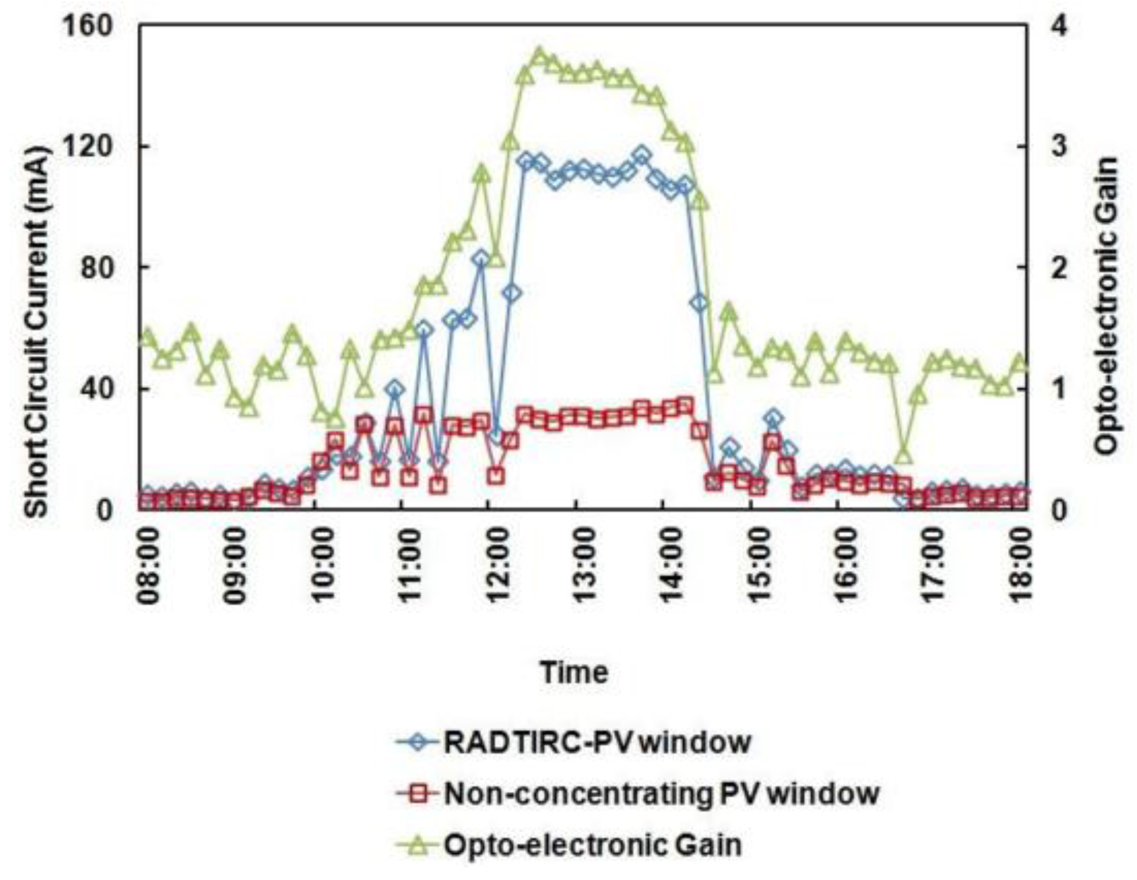
| Generate more electrical output when the LCPV is compared with a non-concentrating design that uses the same area of PV material. The concentrator increases the opto-electronic gain under both direct and diffuse radiations [33]. | May operate at higher temperatures than a conventional rack-mounted PV because they are integrated to the surface of the building and therefore prevents airflow between the modules and the host structure [30]. A higher temperature will lower the electrical output of the panel and may degrade the PV material of the module. |
| Eliminate the need for electromechanical sun tracking system due to its wide half-acceptance angle [34]. | Tends to produce less electricity than conventional rack-mounted PV because it might not be integrated at optimum angle with respect to the sun and the problem with shadowing from surrounding buildings [30]. |
| The land area requirement can be eliminated since the installation is carried out on an existing building structure [34]. This is beneficial especially for installation in urban areas. | Require complex design requirement which revolves around identifying the ‘perfect’ balance between the output power, the system cost and the aesthetics [35]. This is different than the conventional roof/façade-mounted PV system which focuses only on either electricity or aesthetics. Therefore, any installation of a BICPV system needs to take into account building process, building physics, energetic design, aesthetical concept and economical concept [34,35]. |
| The electricity generated can be consumed by the building, which reduces the electricity bill since the generation coincide with the electricity demand of the day. Additionally, the electricity could also be fed back into the national grid [36]. | A BICPV system not only generates electricity, but it also acts as parts of the building structure. Therefore, it needs to comply with the codes and standards of both PV and construction industries [30]. This means that it not only needs to adhere to the qualification and design standards of a PV module, it must also meet the criteria of a building structure, e.g., stability, wind resistance, durability, fire safety, etc. [37]. This creates a market handicap for the BICPV system when compared to the conventional roof/façade-mounted PV system [30]. |
| The co-generated heat can be used to heat/cool the building interior, reducing the heating/cooling requirement of a building [38]. | There is a huge variety of BICPV products, either by façade type (e.g., curtain walls, windows, roof shingles and awnings) [30] or by design (e.g., geometries and materials) [34]. This leads to BIPV market being focused on custom-design segment which hinders the scalability of BIPV technology. In addition to that, its limitation of only being suitable for residential and commercial building integration eliminates its prospect to compete with utility-scale and ground-mount space [30]. |
| The arrangement of the PV cells can be designed in such a way that it could allow natural illumination into the building, which could reduce the lighting requirement of a building [38]. | |
| The losses due to transmission and distribution of electricity can be minimized because the electricity is consumed onsite [34]. | |
| A BICPV system can enhance the aesthetic appearance of a building by introducing innovative ways of integrating the panel in the building [17]. |
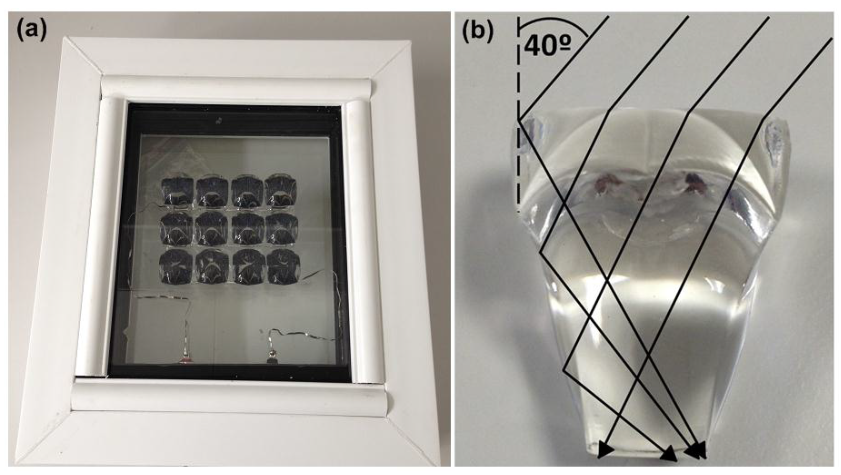
| Item | Computer-Aided Design (CAD) | First RADTIRC Prototype | Second RADTIRC Prototype |
|---|---|---|---|
Photograph (refer axis below) | 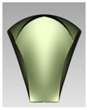 | 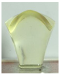 | 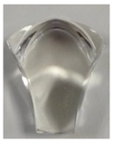 |
| Material | n/a * | 6091 | PMMA |
| Fabrication technique | n/a * | Silicon moulding | Injection moulding |
| Length along x-axis (cm) | 2.21 | 2.14 | 2.28 |
| Change with respect to the CAD design—along x-axis (%) | n/a * | −2.99 | 3.35 |
| Length along y-axis (cm) | 2.64 | 2.55 | 2.57 |
| Change with respect to the CAD design—along y-axis (%) | n/a * | −3.26 | −2.50 |
| Area (cm2) | 5.815 | 5.46 | 5.86 |
| Change with respect to the CAD design—Area (%) | n/a * | −6.10 | 0.77 |
| Maximum Short circuit current, Isc (mA) | n/a * | 140.00 | 159.00 |
| Open circuit voltage, Voc (V) | n/a * | 0.61 | 0.61 |
| Maximum Power, Pmax (mW) | n/a * | 66.38 | 75.91 |
| Maximum Optical efficiency, Ceff (%) | 94.20 | 80.14 | 91.27 |
| Maximum Opto-electronic gain, Copt | 4.62 | 3.93 | 4.48 |
| Fill Factor, FF (%) | n/a * | 77.72 | 78.26 |
| Maximum Electrical conversion efficiency, η (%) | n/a * | 13.45 | 15.45 |
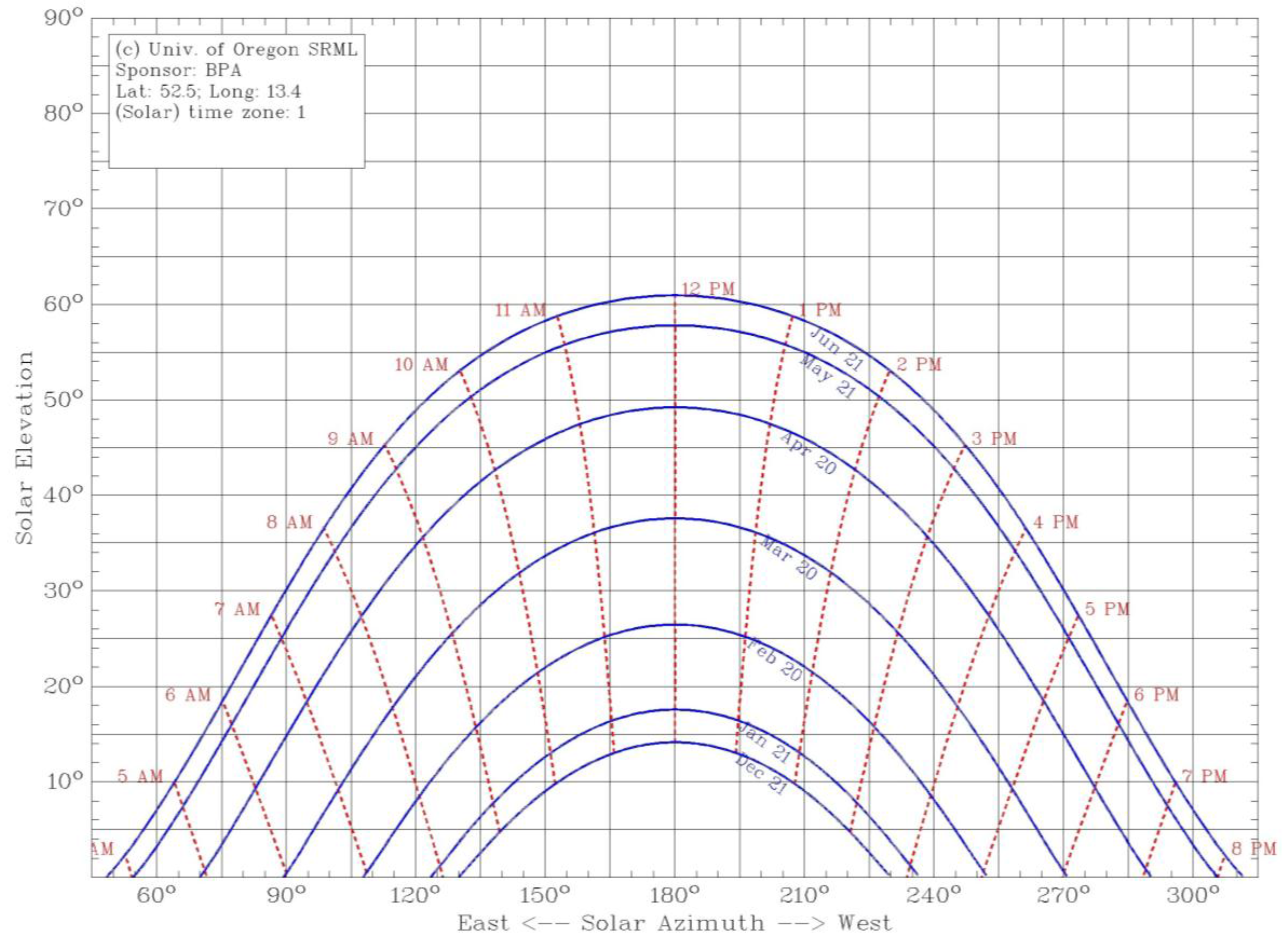
| Month | Maximum Solar Altitude Angle, γs (°) | Maximum Angle of Incidence at a 53° Tilted Plane (°) |
|---|---|---|
| June | 60 | 23 |
| May/July | 53 | 16 |
| April/August | 45 | 8 |
| March/September | 37 | 0 |
| February/October | 29 | 8 |
| January/November | 21 | 16 |
| December | 14 | 23 |
© 2018 by the authors. Licensee MDPI, Basel, Switzerland. This article is an open access article distributed under the terms and conditions of the Creative Commons Attribution (CC BY) license (http://creativecommons.org/licenses/by/4.0/).
Share and Cite
Freier, D.; Muhammad-Sukki, F.; Abu-Bakar, S.H.; Ramirez-Iniguez, R.; Munir, A.B.; Mohd Yasin, S.H.; Bani, N.A.; Mas’ud, A.A.; Ardila-Rey, J.A.; Karim, M.E. Annual Prediction Output of an RADTIRC-PV Module. Energies 2018, 11, 544. https://doi.org/10.3390/en11030544
Freier D, Muhammad-Sukki F, Abu-Bakar SH, Ramirez-Iniguez R, Munir AB, Mohd Yasin SH, Bani NA, Mas’ud AA, Ardila-Rey JA, Karim ME. Annual Prediction Output of an RADTIRC-PV Module. Energies. 2018; 11(3):544. https://doi.org/10.3390/en11030544
Chicago/Turabian StyleFreier, Daria, Firdaus Muhammad-Sukki, Siti Hawa Abu-Bakar, Roberto Ramirez-Iniguez, Abu Bakar Munir, Siti Hajar Mohd Yasin, Nurul Aini Bani, Abdullahi Abubakar Mas’ud, Jorge Alfredo Ardila-Rey, and Md Ershadul Karim. 2018. "Annual Prediction Output of an RADTIRC-PV Module" Energies 11, no. 3: 544. https://doi.org/10.3390/en11030544