Energy Hub’s Structural and Operational Optimization for Minimal Energy Usage Costs in Energy Systems


1
School of Electric Power, South China University of Technology, Guangzhou 510641, China
2
Department of Electric Power Systems, Thai Nguyen University of Technology, Thai Nguyen 250000, Vietnam
3
College of Electric and Information Engineering, Hunan University, Changsha 410082, China
*
Author to whom correspondence should be addressed.
Energies 2018, 11(4), 707; https://doi.org/10.3390/en11040707
Submission received: 7 February 2018
/
Revised: 11 March 2018
/
Accepted: 12 March 2018
/
Published: 21 March 2018
(This article belongs to the Section F: Electrical Engineering)
Abstract
:The structural and optimal operation of an Energy Hub (EH) has a tremendous influence on the hub’s performance and reliability. This paper envisions an innovative methodology that prominently increases the synergy between structural and operational optimization and targets system cost affordability. The generalized energy system structure is presented theoretically with all selective hub sub-modules, including electric heater (EHe) and solar sources block sub-modules. To minimize energy usage cost, an energy hub is proposed that consists of 12 kinds of elements (i.e., energy resources, conversion, and storage functions) and is modeled mathematically in a General Algebraic Modeling System (GAMS), which indicates the optimal hub structure’s corresponding elements with binary variables (0, 1). Simulation results contrast with 144 various scenarios established in all 144 categories of hub structures, in which for each scenario the corresponding optimal operation cost is previously calculated. These case studies demonstrate the effectiveness of the suggested model and methodology. Finally, avenues for future research are also prospected.
1. Introduction
Nowadays, interdependent and interactional energy vectors have been continuing for stimulating the proliferation of Energy Hub (EH) modeling techniques [1,2,3,4,5]. To facilitate the accomplishment of terminal units’ energy consumption with low-carbon and high efficiency, energy capture, conversion, and storage sections through a vertical value chain can be coordinated at a high integration level in the form of an EH model composed of transformers, micro-turbines, central air conditioners, compressors, and energy storage devices [6]. The efficiency of an EH has been taken into account for evaluation in various areas, e.g., energy consumption optimization [7,8], high-efficiency use in integrated energy systems, and flexible response under diversified loads scenarios [9,10].
Recently, several studies on EHs have been chiefly concentrating on ensuring optimum performance under different types of loads (applied in an energy system). Typically, these studies reshape an EH model’s structure by including special components. The modified EH model containing an air conditioner has higher cost-efficiency than the independent natural gas and electricity networks [11]. The EH efficiency can be improved by installing energy storage devices [12,13]. An innovative energy hub extended with a battery energy storage system (BESS), solar thermal equipment (SHE), and solar photovoltaic (PV) generation optimizes total residential energy costs [14]. Considering the accommodation of renewable energy, such as wind and solar, under different climates, short-term schedules in an energy hub are explored to investigate minimum operation costs [15]. It is obvious that the optimal energy supply for additional loads depends partly on the hub’s operation, but mostly on the hub’s structure and its properties. Many other publications considering an EH’s system lectotype for the optimal structure are gaining traction. The linear method is applied to a hub’s structural and operational optimization problem by selecting the optimal elements installation capacity, irrespective of how the hub’s structure is modified [16]. Research [17] has performed optimization calculations with 12 different structured operating scenarios.
There is no doubt that components selection in an EH has a great impact on system performance quality. Maintaining the optimal output effects of an EH will not only rely on appropriate operation modes but also on its architecture as well as the properties of conversion and storage elements. Such results found in the above studies [16,17], despite obtaining the optimum model, are highly complex when being computed due to listing all of the categories of structures. In order to achieve the global optimum conditions for supplying energy, it is quite essential to develop the optimization research issues by focusing on hub system structure and operation simultaneously. However, most studies ignore this joint optimization problem and just pay close attention to only a single perspective.
Consequently, it is necessary to establish a mathematical model to rapidly identify the optimal model structure that simultaneously satisfies two objectives: optimizing operating costs and selecting the optimal operating structure. The objective of our investigation is to penetrate into this joint optimization problem with a handy calculation method.
In this study, a generalized EH model will be introduced based on the system equipment in the energy distribution network model (Figure 1). The objective total energy cost function in 24 h of operation is minimized with constraints, i.e., energy balance, system capacity limitations, energy charge/discharge capacity in energy storages, electricity, and natural gas prices. The General Algebraic Modeling System (GAMS) high-level programming language is used to solve optimal operating problems. In a GAMS simulation, the binary variables (0, 1) are used for expressing the presence of the corresponding device in the model. The expected results will simultaneously fulfill the need for a model’s structural and operational optimization, further enhancing the optimization of such a double objectives problem. These optimization effects become reliable evidence for selecting the appropriate structures when minimizing the costs of energy consumption.
Aiming at delivering a distinctive solution to fulfill two research objectives, hub operation optimization and optimal structure identification, our research covers EH theory, the EH optimization problem, the mathematical model built in GAMS, and simulation results and discussion. The remaining sections will be presented as follows. The basic proposed Energy Hub model and the energy system’s general structure are described in Section 2, in which the optimization problem based on EH structure is also included. The mathematical model, including objective functions with their corresponding constraints, is developed in Section 3. The element availability presentation is actualized by 12 binary variables. In Section 4, calculation results of total operating cost under each scenario are compared to validate the feasibility of the proposed optimization methodology, in which the optimal structure is proved to generate the lowest energy cost. Finally, conclusions and future tendencies are summarized in Section 5.
2. Design of the Model
2.1. The Energy System’s Structure
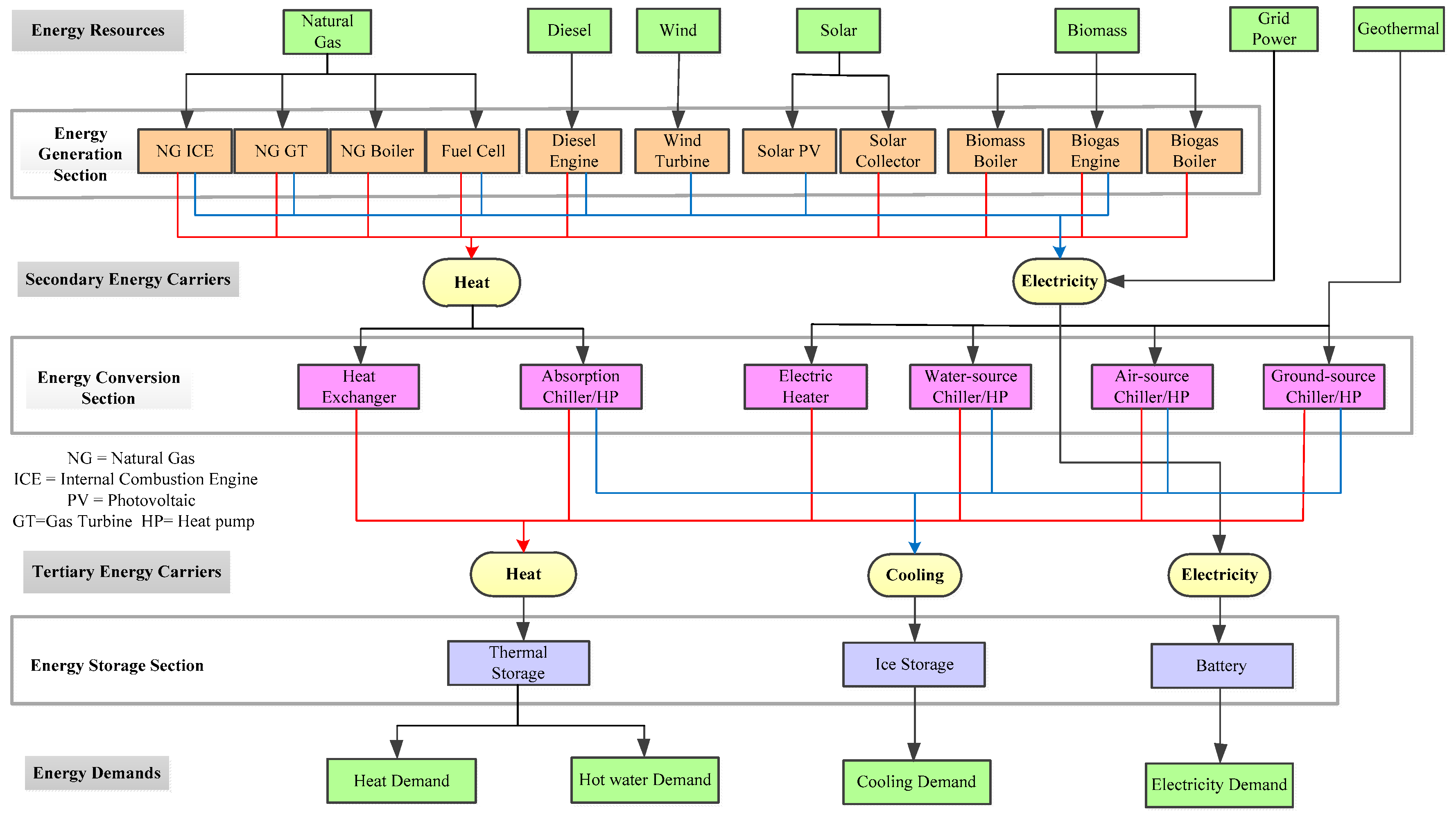
From a system point of view, the general structure of the energy system undertakes the mainstays of energy exploitation, conversion, and storage in Figure 1. The system architecture is organized into three sections, i.e., generation, conversion, and storage. Correspondingly, from a value chain perspective, the energy transfer mechanism operates with these three sections successively. Primary energy resources are converted into heat and electricity by a variety of generation technologies in the energy generation section. Then, the secondary energy carriers, i.e., heat and electricity, are converted to different forms of tertiary energy carriers, i.e., heat, cooling, and electricity, by various conversion technologies in the energy conversion section. Taking a water-source heat pump as an example, this conversion technology can produce cooling and heat by utilizing geothermal energy. For the sake of peak load shifting, spatial and temporal optimum operation can be performed with storage devices. The energy system can entirely satisfy terminal users’ energy demands.
Commonly, twenty types of equipment are employed in the energy system, in which the most prevailing kinds of generation, conversion, and storage technologies are covered. Hence, these provide various configurations to establish the energy hub models, and the inclusion of all possible energy technologies does not imply that all of them will be adopted.
2.2. The Structural Optimization of Hub Modeling
2.2.1. Energy Hub Concept
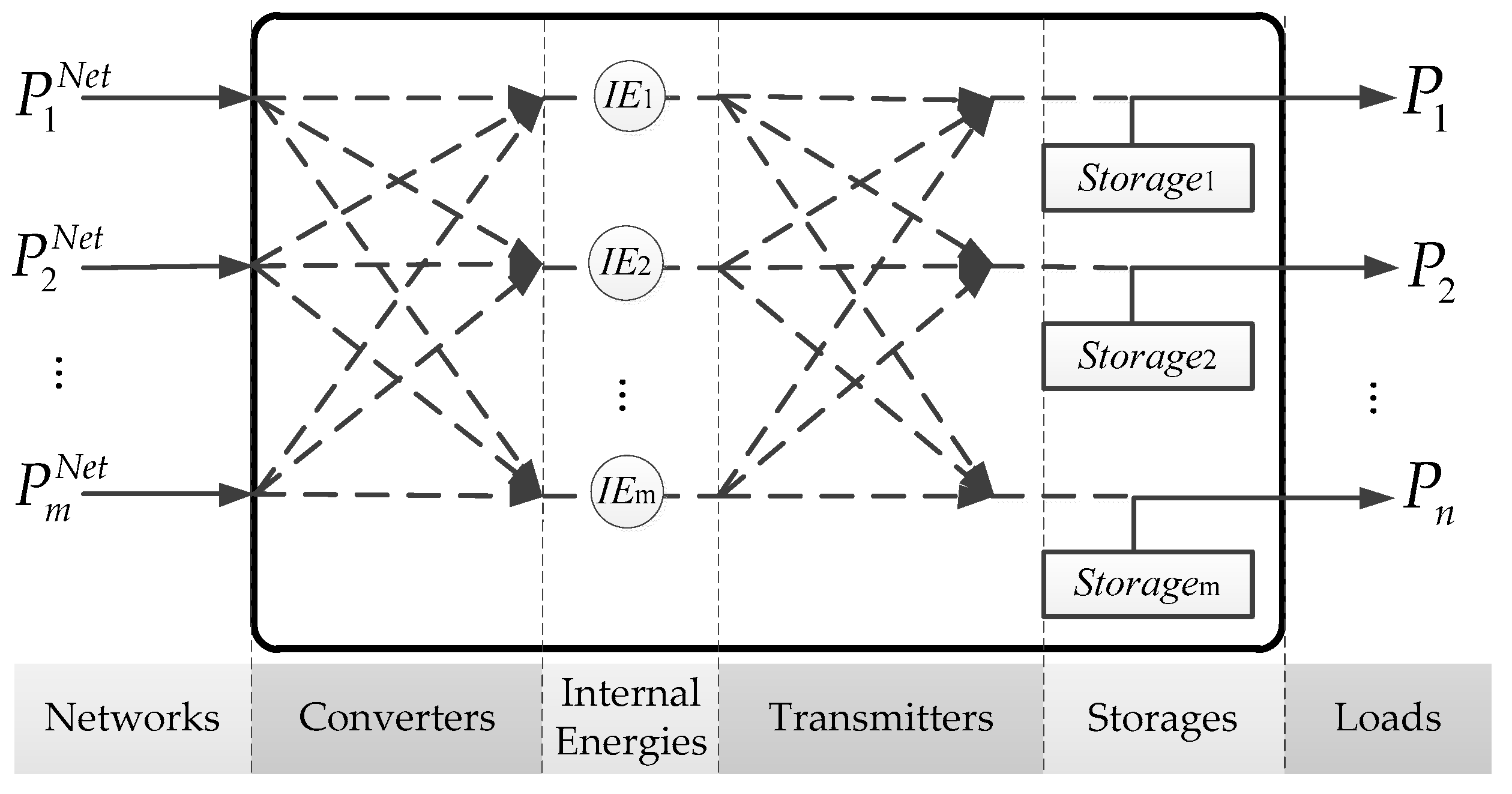
The network node in the energy system can be extended as an energy hub which interfaces energy carriers and features in any configuration of the energy generation, conversion, and storage elements in Figure 2. With simplifications, the coupling energy flow can be delivered through the hub with multi-input and multi-output [3].
2.2.2. Proposed Energy Hub Model
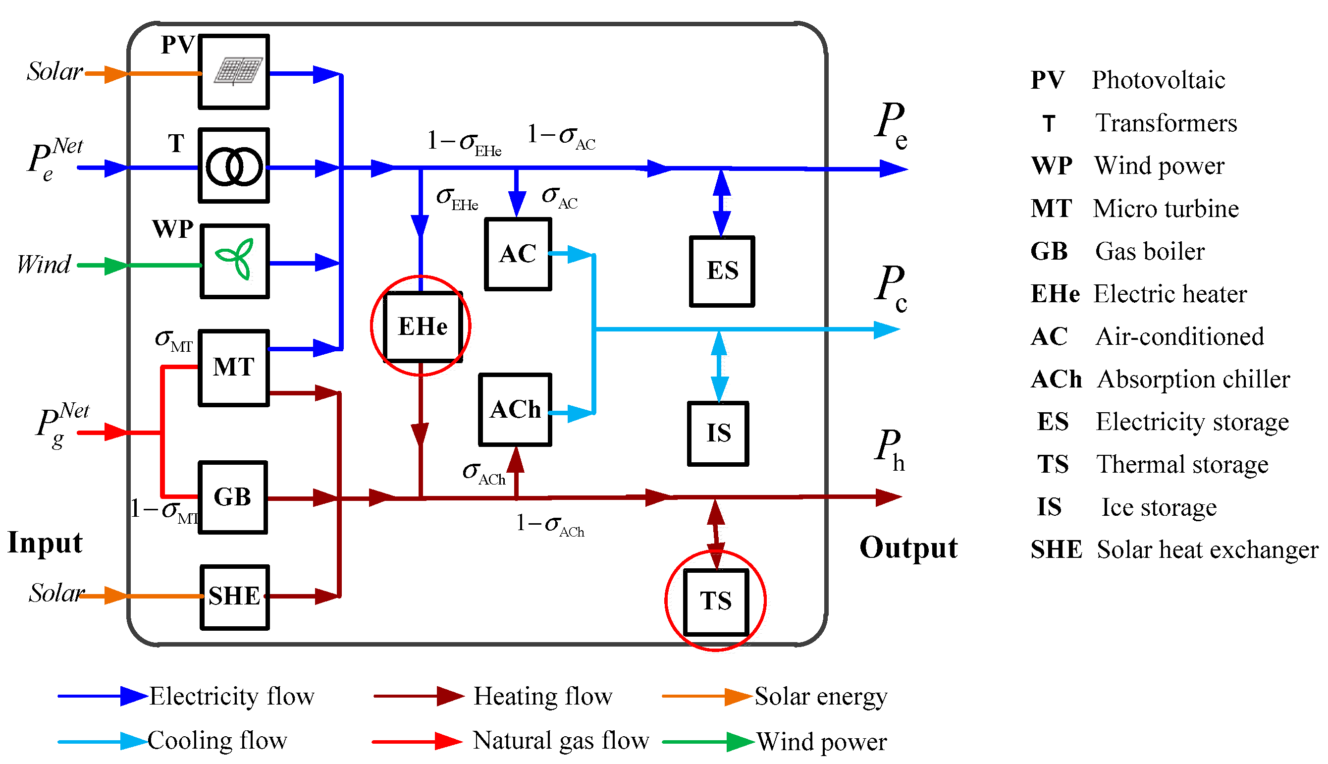
For representing the complete functions of the energy system’s general structure mentioned above, an innovative structured Energy Hub model is proposed in Figure 3. First of all, all different sub-modules are taken into account, including energy generation, i.e., electricity, natural gas, and decentralized renewables (wind energy and solar energy) as hub system input. Multiple hub energy vectors—natural gas, electricity, heating, and cooling—are bridged by conversion elements, which consist of voltage transformer, micro turbine (MT), air-conditioning (AC), gas boiler (GB), absorption chiller (ACh), solar heat exchanger (SHE), and electric heater (EHe). Energy storage comprises electricity storage (ES), thermal storage (TS), and ice storage (IS). As for the demand side, only electricity, heating, and cooling loads are considered. Secondly, solar power is transferred into electricity and heating energy by PV and SHE. Besides this, the new trails are blazed by settling the placement of the electric heater (EHe) in the EH model.
The electricity loads are powered by the following components in the proposed energy hub. The electricity is delivered by transformers in electrical systems, MT in natural gas systems, wind power (WP), and PV. The EHe in electrical systems and the MT and GB in natural gas systems supply heat for demands. Moreover, some of the remaining heat is supplemented by solar energy via SHE. The cooling demand is met simultaneously through two AC and ACh devices that are sourced from electrical and natural gas systems separately.
2.2.3. The Optimization Problem of EH Structure
The optimization problem statement is given to minimize the cost of energy use by selecting the optimal operating structure, in which there are 12 selected elements from the proposed energy hub model as presented in Figure 3. When the energy hub is described as a block box as shown in Figure 4, the optimal structure contributes to the combinatorial optimization of the selected elements. As a prerequisite, the energy hub still maintains the coupling of supply and demands in a synthetic way with the balance between multi-output and multi-input energy.
Targeting the simultaneous identification of the optimal structure and optimal operation of the model, the optimization model comprises on/off-type variables assigned to each available element. The integer variable represents the determination on whether element f is used in the hub model or not:
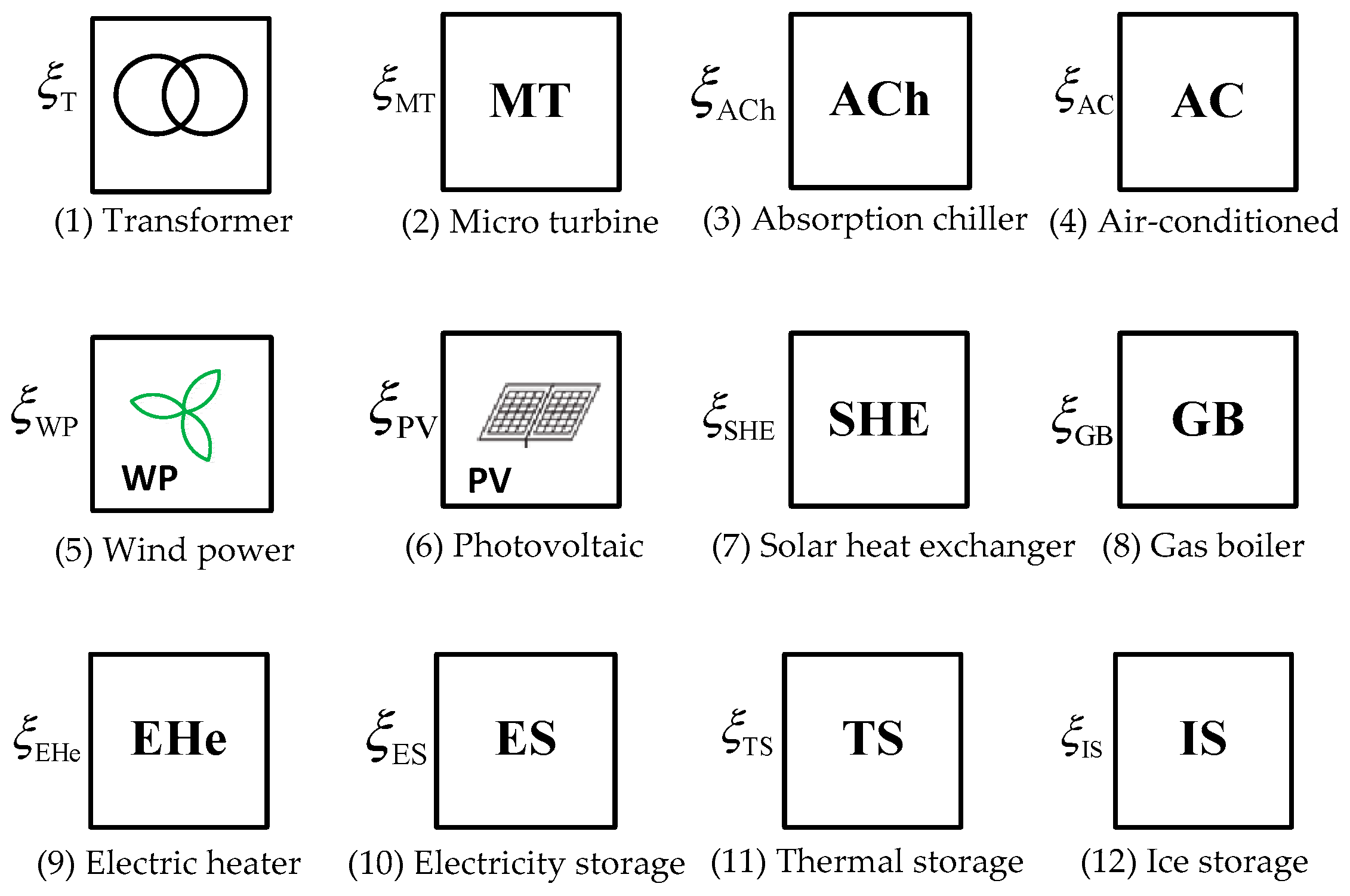
As depicted in Figure 5, a set of elements are available for the desired hub and the appropriate ones can be selected for structural optimization. The binary variables , , , , , , , , , , , and demonstrate the involvement of 12 corresponding devices forming the energy hub in the model. The mathematical model containing the objective function and constraints will be introduced in Section 3.
3. Mathematical Model
3.1. The Objective Function
An energy hub is economically scheduled based on the minimum energy costs that depend on the daily consumption of electricity and heat. The objective function is given as:
where and are the electricity and natural gas prices at hour t, respectively.
3.2. Constraints
3.2.1. Energy Balance
The energy balance constraints are in expression associated with 12 binary variables corresponding to the devices which were introduced in Figure 5. The relationship between multi-input and multi-output is presented in (4a), (4b), and (4c) as follows:
- -
- Electricity power balance:
- -
- Heating balance:
- -
- Cooling balance:
where the output energy flows, including , , and are the electricity, heat, and cooling demands at hour t, respectively; and are the input energy (electricity and natural gas) at hour t, respectively; , , , , , , and are the conversion efficiency of the transformers MT, GB, AC, ACh, and EHe, respectively; , , , and are the dispatch ratios of electricity, natural gas, and heat conversion through AC, MT, ACh, and EHe devices at hour t, respectively; , , are the generation power of the distributed energy resources PV, PW, and SHE at hour t, respectively; and the charge/discharge power capacity in the energy storage devices (electricity, heat, and cooling) are denoted by at hour t, respectively.
3.2.2. Network Constraints
The inputs of electricity and natural gas are constrained by the upper limits and , which are shown in (5a) and (5b):
3.2.3. Conversion Limitations
The proposed model’s operation is based on energy flow dispatched by AC, MT, ACh, and EHe devices. The dispatch ratios determine which part of the input energy flow, not exceeding the permitted limitations, is converted by the equipment. The constraints of these state variables are introduced in expression (6):
where , , , and are the dispatch ratios of AC, MT, ACh, and EHe at time t, respectively.
3.2.4. Storage Constraints
In the proposed model, three types of energy storage section devices are employed simultaneously, i.e., ES, TS, and IS, with the same working principles and effects. The storage section is more accurately investigated when considering the energy loss indicated by coefficient and the constraints of their charge/discharge durations [12,20]. Energy storage and power limits at the time (t) are introduced with the expression (7a). Energy losses during charge/discharge are introduced with the equality constraint (7b). The charge/discharge limits are introduced in the inequality constraint (7c). The limit of device operation mode (discharge or charge) device is introduced in the inequality constraints (7d) and (7e) associated with the binary variables (7f). The charge/discharge power characteristics of the device usually repeat in a cycle of 24 h. Therefore, the calculation cycle is selected at T = 24 h. The energy balance constraint in the calculation cycle is shown in the expression (7g).
3.2.5. Energy Prices
There is a predominance of energy prices in the objective function (3). The optimization problem considers the prices of electricity and natural gas. The natural gas price is a constant and is expressed by [21]. Various dynamic pricing methods may be available for electricity customers in the residential sector. Fixed Rate Price (FRP), Time of Use (TOU), and Real Time Pricing (RTP) are three types of dynamic pricing currently used in various utilities [22]. RTP is applied in the calculation in which the hourly electricity price varies continuously and reflects the wholesale electricity market price or day-ahead price. This provides a direct linkage between the wholesale and retail energy markets, showing that the changing supply/demand balance of the system introduces the price elasticity of customers [18].
4. Simulation Result
In this section, illustrative examples will be employed in an optimization problem with the objective function (3) satisfying the simultaneous constraints from Equations (4)–(7) and energy prices. In order to verify this model, these studies are carried out with 144 operational structures that comprise all kinds of energy devices to generate all possible alternatives. Assuming that the demands, composed of electricity, cooling, and heat, remain the same, the verification is conducted in comparisons between 144 structures. The binary numbers (0, 1) are used for expressing whether each device in the hub is available or not. All scenarios’ optimal operation costs are shown, in which we evaluate the effectiveness of our model.
4.1. Hub Data Description
The hourly demand for calculation includes electricity, heat, and cooling. Furthermore, energy supply prices, energy system capacity, and parameters of devices, such as PV, WP, SHE, and storage devices, will be given in following descriptions.
4.1.1. Electricity, Heat, and Cooling Demand
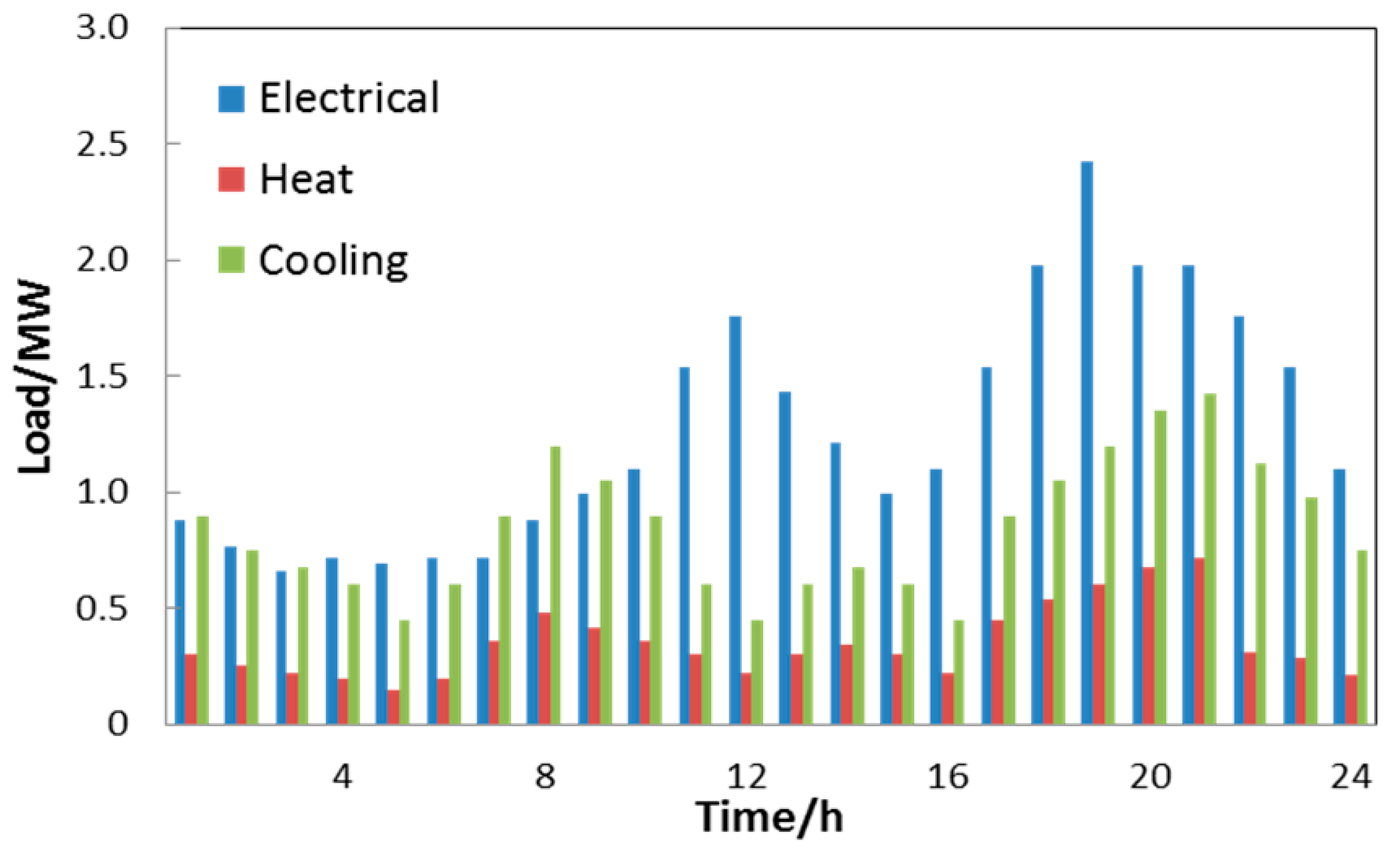
The demands of energy carriers, including electricity, heat, and cooling, fluctuating over 24 h are based on references [11,14,23,24] and plotted in Figure 6. Commonly, the electricity consumption is higher than that of heat and cooling. The peak value of electricity can reach to 2.2 MW, while the highest demand for heat and the highest demand for cooling are 0.48 MW and 0.95 MW, respectively.
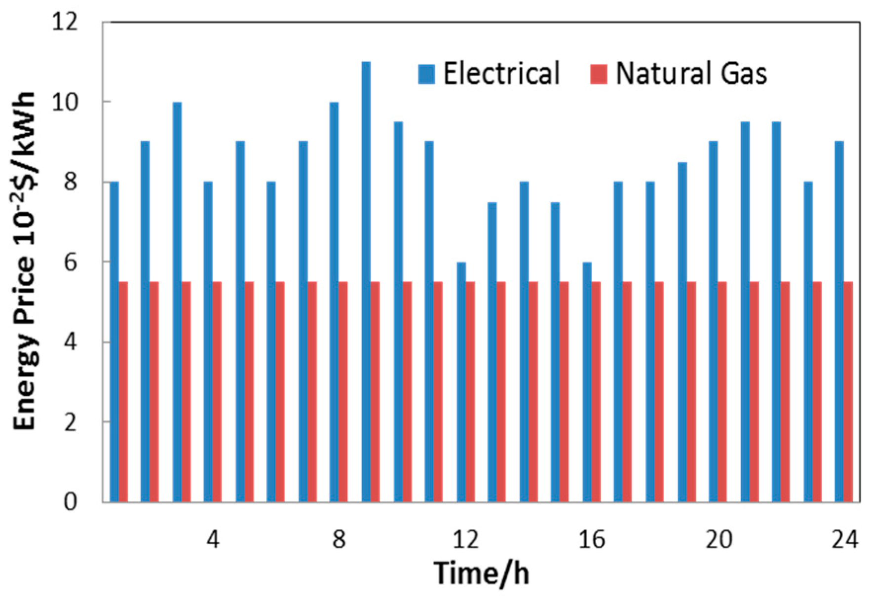
4.1.2. Energy Price
Energy prices play a critical role in the objective function (3), from which natural gas and electricity prices are reflected in the optimization problem. In particular, for electricity pricing, we employ the involvement of real-time pricing (RTP) from an electricity market [18,20,25] while keeping the natural gas prices constant [23]. The energy tariffs are displayed according to Figure 7 as follows:
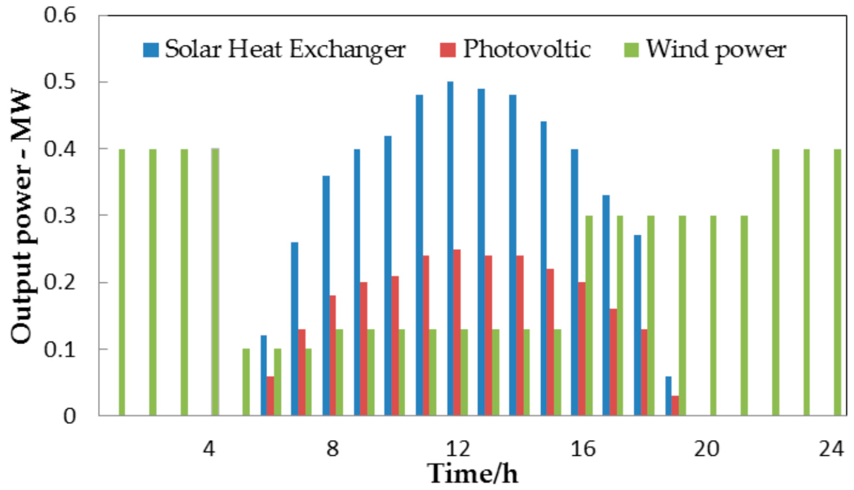
4.1.3. Solar and Wind Power
4.1.4. Device Parameters and System Capacity Limitations
4.2. Calculation Result
The hub optimization problem that is proposed above can be solved by solver BONMIN in GAMS (23.5.1, GAMS Development Corporation, Fairfax, VA, USA) [27], and the solution process is shown by the user-defined algebra calculation algorithm in the block diagram in Figure 9.
During the optimization, the optimal operating structure generates the lowest total energy cost of only $2968 per day. Under such a circumstance, the two devices EHe and TS are not involved, in which the corresponding binary variables are both zeros. The optimal hub structure, as shown in Figure 10, is reduced by two elements compared with the original proposed EH model structure in Figure 3.
To further verify the efficiency of the proposed method, the computations are performed with all 144 operating scenarios as demonstrated in Table A1-Annex. In particular, all of the energy demands can be fulfilled during the operation of all hub structures. The extreme values are compared in Table 3: Case 1 brings the highest cost of $5136 per day, while Case 44 generates the lowest cost of $2968 per day. Besides this, the proposed EH model produces the total cost of $2975 per day.
This proposed optimization method is affirmed to coincide with the verification of 144 operating scenarios computations. We can admit that the methodology provides the optimal structure and operation simultaneously. As shown in Table 3, the optimal operation cost under the optimal operating structure is $2968 per day. Meanwhile, the lowest operating cost is also $2968 per day in Case 44 when compared with the 144 scenario computations.
Apparently, in Case 144, the proposed energy hub, with all components involved, owns a relatively low total cost and does not differ greatly from Case 44 in structure. The input energy, including electricity and natural gas, for Case 1, Case 44, and Case 144 is introduced in Figure 11. The energy storage sections are both considered in Case 44 and Case 144. In Figure 12, the charge/discharge power characteristics of the energy storage sections are plotted, in which energy is stored at the lowest price hours and emitted at the highest electricity price hours for peak load shifting.
The calculation result of the input energy for the highest operating cost scenario (Case 1) is shown in Figure 11a. In this case, the amount of electricity and natural gas bought from supply networks is relatively high due to the absence of distributed energy resources (PV, WP, and SHE) and storage devices. Specifically, the highest purchase of electricity is 3.48 MW at 7 p.m., while the highest purchased volume for natural gas reaches 1.44 MW at 9 p.m.
As for the optimal operating scenario (Case 44), the input energy of the electricity and natural gas purchased from the supply networks shown in Fig 11.b indicates that: the heat generated by SHE and the electricity from PV and WP combined with ES and IS (Figure 12) have led to a significant change in energy supply, especially as regards electricity. Specifically, the highest electricity input is only 1.26 MW at 12 a.m. This results in the total energy cost of $2968, which is a significant reduction compared to the total energy cost in Case 1 of $5136.
For Case 144 (shown in Figure 3), it is observed that the input power characteristics are not much different from Case 44. The total energy purchased from the supply networks in this scenario is also not much different from the optimal Case 44. It is a fact that the heat storage device and EHe are involved in the EH’s energy storage and conversion, leading to a change in energy distribution across the devices in the model. At the same time, due to the device conversion efficiency being less than 100%, there is an additional amount of energy loss, which results in an insignificant increase in energy costs compared to Case 44.
4.3. Result Discussions
According to the calculations mentioned above, we can make some comments as follows:
- (1)
- The solution of the optimization problem for both optimums in hub structure and operation, associated with binary variables which indicate whether or not devices are involved in the various structured operating scenarios, has given accurate results. The optimal operating model and Case 44 have the same structure and total cost purchased from the system.
- (2)
- The computational results of 144 different structured comparisons in the operating scenarios have highlighted the model structure’s role and impact on the optimal operation efficiency problem characterized in the form of an economic indicator: total energy cost per day (Table A1). Case 44 has critically the lowest daily energy cost ($2968) in contrast to Case 1, which owns the highest energy cost of up to $5136. The difference of the total energy costs between the two scenarios is shown in Table 4.
It is obvious that switching between different structured operating scenarios offers flexible energy supply for electricity, heat, and cooling demands. The listing of all the operational structures also demonstrates the synergies and co-ordinations across elements in the model that can be applied to multi-energy loads. However, we do not consider the situation in which an EH’s structure can be expanded or contracted. The current structure optimization is based on the condition that all elements must be included. However, in some specific scenarios, the enrollment of elements in an EH can just be the partial combination of 12 kinds of elements.
5. Conclusions
This research pioneers the following investigations in minimizing total energy cost in an energy system:
First of all, we review the general energy system structure considering all possible equipment and covering the generation, conversion, and storage sections. An Energy Hub model with 12 kinds of available elements is proposed. The objective function is formulated as minimizing the total cost of electricity and natural gas purchased from the system based on the proposed EH model.
Secondly, this research aims to bridge the gap between hub operation optimization and optimal structure identification. We list 144 different hub structures and calculate the optimal operation cost under each corresponding hub structure scenario. With the comparison of 144 computational results, the optimal operating structure is verified. The results show that the optimization methodology and the mathematical model accurately identify the optimum operating structure that has a great influence on hub efficiency. This optimization provides an option to restructure an energy hub by selecting appropriate elements to improve energy utilization efficiency.
The illustrated case studies results exemplify an energy hub’s optimal structure and the economical optimum is achieved by taking operation costs into account without regard to the following perspectives. One important issue that could be addressed is to increase the constraints in the mathematical model when an element fault happens. Due to the limited paper space, we maintain the hypothesis that all of the elements are under normal operation without discussing an element accident state, in which the additional corresponding constraints are set as binary variables being zero. Furthermore, load uncertainty is not incorporated into this paper and all the electricity, heat, and cooling loads can be predicted and modeled precisely.
Consequently, further investigations should be concentrated on research topics about hub structure and load uncertainty modeling techniques. The possible restructured hub topologies are related to a hub planning optimization problem that involves the consideration of equipment cost, reliability, and utilization. Besides, an equipment environment cost could be another factor contributing to this issue. What is more, we should also engage in hub structure optimization when enlarging external energy networks into multi-energy hub systems. Last but not least, in the light of load uncertainty, robust optimization and flexible planning can be applied to cope with this nondeterminacy problem.
Acknowledgments
This work was supported by National Natural Science Foundation of China (No. 51777077) and Natural Science Foundation of Guangdong Province, China (No. 2017A030313304).
Author Contributions
Thanh Tung Ha and Yongjun Zhang designed the models and completed most of the simulations; Jinbao Hao and V. V. Thang performed some of the simulations in this paper; Canbing Li and Zexiang Cai analysed the data and provided constructive advice on the modelling and writing of the paper; and Thanh Tung Ha and Yongjun Zhang wrote the paper.
Conflicts of Interest
The authors declare no conflict of interest.
Appendix A

Table A1.
Proposed hub operation reports in 144 cases.
| Case- i | T | MT | GB | EHe | AC | ACh | DER | ESS | Total Energy Cost ($/day) | ||
|---|---|---|---|---|---|---|---|---|---|---|---|
| PV/ PW/ SHE | ES | TS | IS | ||||||||
| Output | Electricity | Electricity & Heat | Heat | Heat | Cooling | Cooling | Electricity & Heat | Electricity | Heat | Cooling | |
| Case 1 | 1 | 1 | 1 | 0 | 1 | 0 | 0 | 0 | 0 | 0 | 5136 |
| Case 2 | 1 | 1 | 1 | 0 | 1 | 0 | 1 | 0 | 0 | 0 | 4239 |
| Case 3 | 1 | 1 | 1 | 0 | 1 | 0 | 0 | 1 | 0 | 0 | 5081 |
| Case 4 | 1 | 1 | 1 | 0 | 1 | 0 | 1 | 1 | 0 | 0 | 4188 |
| Case 5 | 1 | 1 | 1 | 0 | 1 | 0 | 0 | 0 | 1 | 0 | 5100 |
| Case 6 | 1 | 1 | 1 | 0 | 1 | 0 | 1 | 0 | 1 | 0 | 4192 |
| Case 7 | 1 | 1 | 1 | 0 | 1 | 0 | 0 | 1 | 1 | 0 | 5058 |
| Case 8 | 1 | 1 | 1 | 0 | 1 | 0 | 1 | 1 | 1 | 0 | 4135 |
| Case 9 | 1 | 1 | 1 | 0 | 1 | 0 | 0 | 0 | 0 | 1 | 5101 |
| Case 10 | 1 | 1 | 1 | 0 | 1 | 0 | 1 | 0 | 0 | 1 | 4177 |
| Case 11 | 1 | 1 | 1 | 0 | 1 | 0 | 0 | 1 | 0 | 1 | 5029 |
| Case 12 | 1 | 1 | 1 | 0 | 1 | 0 | 1 | 1 | 0 | 1 | 4173 |
| Case 13 | 1 | 1 | 1 | 0 | 1 | 0 | 0 | 0 | 1 | 1 | 4973 |
| Case 14 | 1 | 1 | 1 | 0 | 1 | 0 | 1 | 0 | 1 | 1 | 4124 |
| Case 15 | 1 | 1 | 1 | 0 | 1 | 0 | 0 | 1 | 1 | 1 | 4979 |
| Case 16 | 1 | 1 | 1 | 0 | 1 | 0 | 1 | 1 | 1 | 1 | 4066 |
| Case 17 | 1 | 1 | 1 | 0 | 0 | 1 | 0 | 0 | 0 | 0 | 3912 |
| Case 18 | 1 | 1 | 1 | 0 | 0 | 1 | 1 | 0 | 0 | 0 | 3039 |
| Case 19 | 1 | 1 | 1 | 0 | 0 | 1 | 0 | 1 | 0 | 0 | 3849 |
| Case 20 | 1 | 1 | 1 | 0 | 0 | 1 | 1 | 1 | 0 | 0 | 2978 |
| Case 21 | 1 | 1 | 1 | 0 | 0 | 1 | 0 | 0 | 1 | 0 | 3870 |
| Case 22 | 1 | 1 | 1 | 0 | 0 | 1 | 1 | 0 | 1 | 0 | 2986 |
| Case 23 | 1 | 1 | 1 | 0 | 0 | 1 | 0 | 1 | 1 | 0 | 3834 |
| Case 24 | 1 | 1 | 1 | 0 | 0 | 1 | 1 | 1 | 1 | 0 | 2956 |
| Case 25 | 1 | 1 | 1 | 0 | 0 | 1 | 0 | 0 | 0 | 1 | 3856 |
| Case 26 | 1 | 1 | 1 | 0 | 0 | 1 | 1 | 0 | 0 | 1 | 2987 |
| Case 27 | 1 | 1 | 1 | 0 | 0 | 1 | 0 | 1 | 0 | 1 | 3606 |
| Case 28 | 1 | 1 | 1 | 0 | 0 | 1 | 1 | 1 | 0 | 1 | 2965 |
| Case 29 | 1 | 1 | 1 | 0 | 0 | 1 | 0 | 0 | 1 | 1 | 3855 |
| Case 30 | 1 | 1 | 1 | 0 | 0 | 1 | 1 | 0 | 1 | 1 | 2980 |
| Case 31 | 1 | 1 | 1 | 0 | 0 | 1 | 0 | 1 | 1 | 1 | 3842 |
| Case 32 | 1 | 1 | 1 | 0 | 0 | 1 | 1 | 1 | 1 | 1 | 2962 |
| Case 33 | 1 | 1 | 1 | 0 | 1 | 1 | 0 | 0 | 0 | 0 | 3906 |
| Case 34 | 1 | 1 | 1 | 0 | 1 | 1 | 1 | 0 | 0 | 0 | 3025 |
| Case 35 | 1 | 1 | 1 | 0 | 1 | 1 | 0 | 1 | 0 | 0 | 3855 |
| Case 36 | 1 | 1 | 1 | 0 | 1 | 1 | 1 | 1 | 0 | 0 | 2975 |
| Case 37 | 1 | 1 | 1 | 0 | 1 | 1 | 0 | 0 | 1 | 0 | 3867 |
| Case 38 | 1 | 1 | 1 | 0 | 1 | 1 | 1 | 0 | 1 | 0 | 2986 |
| Case 39 | 1 | 1 | 1 | 0 | 1 | 1 | 0 | 1 | 1 | 0 | 3836 |
| Case 40 | 1 | 1 | 1 | 0 | 1 | 1 | 1 | 1 | 1 | 0 | 2957 |
| Case 41 | 1 | 1 | 1 | 0 | 1 | 1 | 0 | 0 | 0 | 1 | 3230 |
| Case 42 | 1 | 1 | 1 | 0 | 1 | 1 | 1 | 0 | 0 | 1 | 2977 |
| Case 43 | 1 | 1 | 1 | 0 | 1 | 1 | 0 | 1 | 0 | 1 | 3597 |
| Case 44 | 1 | 1 | 1 | 0 | 1 | 1 | 1 | 1 | 0 | 1 | 2968 |
| Case 45 | 1 | 1 | 1 | 0 | 1 | 1 | 0 | 0 | 1 | 1 | 3858 |
| Case 46 | 1 | 1 | 1 | 0 | 1 | 1 | 1 | 0 | 1 | 1 | 2982 |
| Case 47 | 1 | 1 | 1 | 0 | 1 | 1 | 0 | 1 | 1 | 1 | 3854 |
| Case 48 | 1 | 1 | 1 | 0 | 1 | 1 | 1 | 1 | 1 | 1 | 2958 |
| Case 49 | 1 | 1 | 0 | 1 | 1 | 0 | 0 | 0 | 0 | 0 | 5136 |
| Case 50 | 1 | 1 | 0 | 1 | 1 | 0 | 1 | 0 | 0 | 0 | 4239 |
| Case 51 | 1 | 1 | 0 | 1 | 1 | 0 | 0 | 1 | 0 | 0 | 5105 |
| Case 52 | 1 | 1 | 0 | 1 | 1 | 0 | 1 | 1 | 0 | 0 | 4207 |
| Case 53 | 1 | 1 | 0 | 1 | 1 | 0 | 0 | 0 | 1 | 0 | 5090 |
| Case 54 | 1 | 1 | 0 | 1 | 1 | 0 | 1 | 0 | 1 | 0 | 4090 |
| Case 55 | 1 | 1 | 0 | 1 | 1 | 0 | 0 | 1 | 1 | 0 | 5042 |
| Case 56 | 1 | 1 | 0 | 1 | 1 | 0 | 1 | 1 | 1 | 0 | 4136 |
| Case 57 | 1 | 1 | 0 | 1 | 1 | 0 | 0 | 0 | 0 | 1 | 5073 |
| Case 58 | 1 | 1 | 0 | 1 | 1 | 0 | 1 | 0 | 0 | 1 | 4177 |
| Case 59 | 1 | 1 | 0 | 1 | 1 | 0 | 0 | 1 | 0 | 1 | 5018 |
| Case 60 | 1 | 1 | 0 | 1 | 1 | 0 | 1 | 1 | 0 | 1 | 4125 |
| Case 61 | 1 | 1 | 0 | 1 | 1 | 0 | 0 | 0 | 1 | 1 | 5033 |
| Case 62 | 1 | 1 | 0 | 1 | 1 | 0 | 1 | 0 | 1 | 1 | 4121 |
| Case 63 | 1 | 1 | 0 | 1 | 1 | 0 | 0 | 1 | 1 | 1 | 4996 |
| Case 64 | 1 | 1 | 0 | 1 | 1 | 0 | 1 | 1 | 1 | 1 | 4080 |
| Case 65 | 1 | 1 | 0 | 1 | 0 | 1 | 0 | 0 | 0 | 0 | 3910 |
| Case 66 | 1 | 1 | 0 | 1 | 0 | 1 | 1 | 0 | 0 | 0 | 3035 |
| Case 67 | 1 | 1 | 0 | 1 | 0 | 1 | 0 | 1 | 0 | 0 | 3848 |
| Case 68 | 1 | 1 | 0 | 1 | 0 | 1 | 1 | 1 | 0 | 0 | 2978 |
| Case 69 | 1 | 1 | 0 | 1 | 0 | 1 | 0 | 0 | 1 | 0 | 3884 |
| Case 70 | 1 | 1 | 0 | 1 | 0 | 1 | 1 | 0 | 1 | 0 | 2993 |
| Case 71 | 1 | 1 | 0 | 1 | 0 | 1 | 0 | 1 | 1 | 0 | 3833 |
| Case 72 | 1 | 1 | 0 | 1 | 0 | 1 | 1 | 1 | 1 | 0 | 2974 |
| Case 73 | 1 | 1 | 0 | 1 | 0 | 1 | 0 | 0 | 0 | 1 | 3875 |
| Case 74 | 1 | 1 | 0 | 1 | 0 | 1 | 1 | 0 | 0 | 1 | 3006 |
| Case 75 | 1 | 1 | 0 | 1 | 0 | 1 | 0 | 1 | 0 | 1 | 3840 |
| Case 76 | 1 | 1 | 0 | 1 | 0 | 1 | 1 | 1 | 0 | 1 | 2988 |
| Case 77 | 1 | 1 | 0 | 1 | 0 | 1 | 0 | 0 | 1 | 1 | 3846 |
| Case 78 | 1 | 1 | 0 | 1 | 0 | 1 | 1 | 0 | 1 | 1 | 2992 |
| Case 79 | 1 | 1 | 0 | 1 | 0 | 1 | 0 | 1 | 1 | 1 | 3383 |
| Case 80 | 1 | 1 | 0 | 1 | 0 | 1 | 1 | 1 | 1 | 1 | 2978 |
| Case 81 | 1 | 1 | 0 | 1 | 1 | 1 | 0 | 0 | 0 | 0 | 3906 |
| Case 82 | 1 | 1 | 0 | 1 | 1 | 1 | 1 | 0 | 0 | 0 | 3025 |
| Case 83 | 1 | 1 | 0 | 1 | 1 | 1 | 0 | 1 | 0 | 0 | 3855 |
| Case 84 | 1 | 1 | 0 | 1 | 1 | 1 | 1 | 1 | 0 | 0 | 2979 |
| Case 85 | 1 | 1 | 0 | 1 | 1 | 1 | 0 | 0 | 1 | 0 | 3862 |
| Case 86 | 1 | 1 | 0 | 1 | 1 | 1 | 1 | 0 | 1 | 0 | 2989 |
| Case 87 | 1 | 1 | 0 | 1 | 1 | 1 | 0 | 1 | 1 | 0 | 3838 |
| Case 88 | 1 | 1 | 0 | 1 | 1 | 1 | 1 | 1 | 1 | 0 | 2996 |
| Case 89 | 1 | 1 | 0 | 1 | 1 | 1 | 0 | 0 | 0 | 1 | 3878 |
| Case 90 | 1 | 1 | 0 | 1 | 1 | 1 | 1 | 0 | 0 | 1 | 3016 |
| Case 91 | 1 | 1 | 0 | 1 | 1 | 1 | 0 | 1 | 0 | 1 | 3835 |
| Case 92 | 1 | 1 | 0 | 1 | 1 | 1 | 1 | 1 | 0 | 1 | 3835 |
| Case 93 | 1 | 1 | 0 | 1 | 1 | 1 | 0 | 0 | 1 | 1 | 2974 |
| Case 94 | 1 | 1 | 0 | 1 | 1 | 1 | 1 | 0 | 1 | 1 | 3848 |
| Case 95 | 1 | 1 | 0 | 1 | 1 | 1 | 0 | 1 | 1 | 1 | 3818 |
| Case 96 | 1 | 1 | 0 | 1 | 1 | 1 | 1 | 1 | 1 | 1 | 2976 |
| Case 97 | 1 | 1 | 1 | 1 | 1 | 0 | 0 | 0 | 0 | 0 | 5130 |
| Case 98 | 1 | 1 | 1 | 1 | 1 | 0 | 1 | 0 | 0 | 0 | 4239 |
| Case 99 | 1 | 1 | 1 | 1 | 1 | 0 | 0 | 1 | 0 | 0 | 5081 |
| Case 100 | 1 | 1 | 1 | 1 | 1 | 0 | 1 | 1 | 0 | 0 | 4186 |
| Case 101 | 1 | 1 | 1 | 1 | 1 | 0 | 0 | 0 | 1 | 0 | 5090 |
| Case 102 | 1 | 1 | 1 | 1 | 1 | 0 | 1 | 0 | 1 | 0 | 4222 |
| Case 103 | 1 | 1 | 1 | 1 | 1 | 0 | 0 | 1 | 1 | 0 | 5035 |
| Case 104 | 1 | 1 | 1 | 1 | 1 | 0 | 1 | 1 | 1 | 0 | 4140 |
| Case 105 | 1 | 1 | 1 | 1 | 1 | 0 | 0 | 0 | 0 | 1 | 5073 |
| Case 106 | 1 | 1 | 1 | 1 | 1 | 0 | 1 | 0 | 0 | 1 | 4177 |
| Case 107 | 1 | 1 | 1 | 1 | 1 | 0 | 0 | 1 | 0 | 1 | 5020 |
| Case 108 | 1 | 1 | 1 | 1 | 1 | 0 | 1 | 1 | 0 | 1 | 4123 |
| Case 109 | 1 | 1 | 1 | 1 | 1 | 0 | 0 | 0 | 1 | 1 | 5027 |
| Case 110 | 1 | 1 | 1 | 1 | 1 | 0 | 1 | 0 | 1 | 1 | 4149 |
| Case 111 | 1 | 1 | 1 | 1 | 1 | 0 | 0 | 1 | 1 | 1 | 4973 |
| Case 112 | 1 | 1 | 1 | 1 | 1 | 0 | 1 | 1 | 1 | 1 | 4088 |
| Case 113 | 1 | 1 | 1 | 1 | 0 | 1 | 0 | 0 | 0 | 0 | 3910 |
| Case 114 | 1 | 1 | 1 | 1 | 0 | 1 | 1 | 0 | 0 | 0 | 3035 |
| Case 115 | 1 | 1 | 1 | 1 | 0 | 1 | 0 | 1 | 0 | 0 | 3859 |
| Case 116 | 1 | 1 | 1 | 1 | 0 | 1 | 1 | 1 | 0 | 0 | 2976 |
| Case 117 | 1 | 1 | 1 | 1 | 0 | 1 | 0 | 0 | 1 | 0 | 3888 |
| Case 118 | 1 | 1 | 1 | 1 | 0 | 1 | 1 | 0 | 1 | 0 | 2993 |
| Case 119 | 1 | 1 | 1 | 1 | 0 | 1 | 0 | 1 | 1 | 0 | 3836 |
| Case 120 | 1 | 1 | 1 | 1 | 0 | 1 | 1 | 1 | 1 | 0 | 2980 |
| Case 121 | 1 | 1 | 1 | 1 | 0 | 1 | 0 | 0 | 0 | 1 | 3854 |
| Case 122 | 1 | 1 | 1 | 1 | 0 | 1 | 1 | 0 | 0 | 1 | 2985 |
| Case 123 | 1 | 1 | 1 | 1 | 0 | 1 | 0 | 1 | 0 | 1 | 3836 |
| Case 124 | 1 | 1 | 1 | 1 | 0 | 1 | 1 | 1 | 0 | 1 | 2966 |
| Case 125 | 1 | 1 | 1 | 1 | 0 | 1 | 0 | 0 | 1 | 1 | 3832 |
| Case 126 | 1 | 1 | 1 | 1 | 0 | 1 | 1 | 0 | 1 | 1 | 2969 |
| Case 127 | 1 | 1 | 1 | 1 | 0 | 1 | 0 | 1 | 1 | 1 | 2981 |
| Case 128 | 1 | 1 | 1 | 1 | 0 | 1 | 1 | 1 | 1 | 1 | 2967 |
| Case 129 | 1 | 1 | 1 | 1 | 1 | 1 | 0 | 0 | 0 | 0 | 5010 |
| Case 130 | 1 | 1 | 1 | 1 | 1 | 1 | 1 | 0 | 0 | 0 | 3025 |
| Case 131 | 1 | 1 | 1 | 1 | 1 | 1 | 0 | 1 | 0 | 0 | 3854 |
| Case 132 | 1 | 1 | 1 | 1 | 1 | 1 | 1 | 1 | 0 | 0 | 2989 |
| Case 133 | 1 | 1 | 1 | 1 | 1 | 1 | 0 | 0 | 1 | 0 | 3861 |
| Case 134 | 1 | 1 | 1 | 1 | 1 | 1 | 1 | 0 | 1 | 0 | 3003 |
| Case 135 | 1 | 1 | 1 | 1 | 1 | 1 | 0 | 1 | 1 | 0 | 3831 |
| Case 136 | 1 | 1 | 1 | 1 | 1 | 1 | 1 | 1 | 1 | 0 | 2982 |
| Case 137 | 1 | 1 | 1 | 1 | 1 | 1 | 0 | 0 | 0 | 1 | 3852 |
| Case 138 | 1 | 1 | 1 | 1 | 1 | 1 | 1 | 0 | 0 | 1 | 2982 |
| Case 139 | 1 | 1 | 1 | 1 | 1 | 1 | 0 | 1 | 0 | 1 | 3840 |
| Case 140 | 1 | 1 | 1 | 1 | 1 | 1 | 1 | 1 | 0 | 1 | 2997 |
| Case 141 | 1 | 1 | 1 | 1 | 1 | 1 | 0 | 0 | 1 | 1 | 3856 |
| Case 142 | 1 | 1 | 1 | 1 | 1 | 1 | 1 | 0 | 1 | 1 | 2996 |
| Case 143 | 1 | 1 | 1 | 1 | 1 | 1 | 0 | 1 | 1 | 1 | 3841 |
| Case 144 | 1 | 1 | 1 | 1 | 1 | 1 | 1 | 1 | 1 | 1 | 2975 |
References
- Paudyal, S.; Cañizares, C.A.; Bhattacharya, K. Optimal Operation of Industrial Energy Hubs in Smart Grids. IEEE Trans. Smart Grid 2015, 6, 684–694. [Google Scholar] [CrossRef]
- Erdener, B.C.; Pambour, K.A.; Lavin, R.B.; Dengyz, B. An integrated simulation model for analysing electricity and gas systems. Electr. Power Energy Syst. 2014, 61, 410–420. [Google Scholar] [CrossRef]
- Barmayoon, M.H.; Fotuhi-Firuzabad, M.; Rajabi-Ghahnavieh, A.; Moeini-Aghtaie, M. Energy storage in renewable-based residential energy hubs. IET Gener. Transm. Distrib. 2016, 10, 3127–3134. [Google Scholar] [CrossRef]
- Chen, S.; Wei, Z.; Sun, G.; Cheung, K.W. Multi-Linear Probabilistic Energy Flow Analysis of Integrated Electrical and Natural-Gas Systems. IEEE Trans. Power Syst. 2017, 32, 1970–1979. [Google Scholar] [CrossRef]
- Shahmohammadi, A.; Moradi-Dalvand, M.; Ghasemi, H.; Ghazizadeh, M.S. Optimal Design of Multicarrier Energy Systems Considering Reliability Constraints. IEEE Trans. Power Deliv. 2015, 30, 878–886. [Google Scholar] [CrossRef]
- Moeini-Aghtaie, M.; Abbaspour, A.; Fotuhi-Firuzabad, M.; Hajipour, E. A decomposed solution to multiple-energy carriers optimal power flow. IEEE Trans. Power Syst. 2014, 29, 707–716. [Google Scholar] [CrossRef]
- Brahman, F.; Honarmand, M.; Jadid, S. Optimal electrical and thermal energy management of a residential energy hub, integrating demand response and energy storage system. Energy Buil. 2015, 90, 65–75. [Google Scholar] [CrossRef]
- Bozchalui, M.C.; Hashmi, S.A.; Hassen, H.; Canizares, C.A.; Bhattacharya, K. Optimal operation of residential energy hubs in smart grids. IEEE Trans. Smart Grid 2012, 3, 1755–1766. [Google Scholar] [CrossRef]
- Rastegar, M.; Fotuhi-Firuzabad, M.; Lehtonen, M. Home load management in a residential energy hub. Electr. Power Syst. Res. 2015, 119, 322–328. [Google Scholar] [CrossRef]
- Bozchalui, M.C.; Canizares, C.A.; Bhattacharya, K. Optimal energy management of greenhouses in smart grids. IEEE Trans. Smart Grid 2014, 6, 827–835. [Google Scholar] [CrossRef]
- Ha, T.T.; Zhang, Y.J.; Huang, J.A.; Thang, V.V. Energy hub modeling for minimal energy usage cost in residential areas. In Proceedings of the 2016 IEEE International Conference on Power and Renewable Energy (ICPRE), Shanghai, China, 21–23 October 2016; pp. 659–663. [Google Scholar]
- Parisio, A.; Del, V.C.; Vaccaro, A. A robust optimization approach to energy hub management. Int. J. Electr. Power Energy Syst. 2012, 42, 98–104. [Google Scholar] [CrossRef]
- Rastegar, M.; Fotuhi-Firuzabad, M.; Zareipour, H.; Moeini-Aghtaieh, M. A probabilistic energy management scheme for renewable-based residential energy hubs. IEEE Trans. Smart Grid 2017, 8, 2217–2227. [Google Scholar] [CrossRef]
- Ha, T.T.; Zhang, Y.J.; Thang, V.V.; Huang, J.A. Energy hub modeling to minimize residential energy costs considering solar energy and BESS. J. Mod. Power Syst. Clean Energy 2017, 5, 389–399. [Google Scholar] [CrossRef]
- Pazouki, S.; Mahmoud-Reza, H.; Javad, O. Effect of Wind Turbine, Solar Cells and Storages in Short Term Operation of Coupled Electricity and Gas Infrastructures in Different Climates. Int. J. Smart Electr. Eng. 2013, 2, 159–165. [Google Scholar]
- Shahmohammadi, A.; Dalvand, M.M.; Ghazizadeh, M.S. Energy hubs’ structural and operational linear optimization with energy storage elements. In Proceedings of the 2011 2nd International Conference on Electric Power and Energy Conversion Systems (EPECS), Sharjah, UAE, 15–17 November 2011; pp. 1–6. [Google Scholar]
- Ha, T.T.; Zhang, Y.J.; Hao, J.B.; Pham, T.H.A. Optimal Operation of Energy Hub with Different Structures for Minimal Energy Usage Cost. In Proceedings of the 2017 2nd International Conference on Power and Renewable Energy, Chengdu, China, 20–23 September 2017; pp. 31–36. [Google Scholar]
- Fan, H.; Chen, Q.; Liu, W.; Li, J.; Chen, Y. Optimal scheduling for energy hub in power markets. In Proceedings of the 2016 IEEE Innovative Smart Grid Technologies-Asia, Melbourne, VIC, Australia, 28 November–1 December 2016; pp. 127–131. [Google Scholar]
- Mohammadi, M.; Noorollahi, Y.; Mohammadiivatloo, B.; Yousefi, H. Energy hub: From a model to a concept–A review. Renew. Sustain. Energy Rev. 2017, 80, 1512–1527. [Google Scholar] [CrossRef]
- Pazouki, S.; Haghifam, M.R.; Moser, A. Uncertainty modeling in optimal operation of energy hub in presence of wind, storage and demand response. Int. J. Electr. Power Energy Syst. 2014, 61, 335–345. [Google Scholar] [CrossRef]
- Gas Commodity Fact Sheet for Maryland Public Service Commission. 2014. Available online: http://www.psc.state.md.us/gas/ (accessed on 20 Otcober 2017).
- A Guide to Electricity Charges Market Participants. Available online: http://www.ieso.caimoweb/role/wholesaleCharges.asp (accessed on 10 October 2017).
- Pazouki, S.; Haghifam, M.R. Scheduling of energy hubs including CCHP, solar and energy storages in different climates. In Proceedings of the 2015 20th Conference on Electrical Power Distribution Networks Conference (EPDC), Zahedan, Iran, 28–29 April 2015; pp. 101–106. [Google Scholar]
- Geidl, M.; Andersson, G. Optimal Coupling of Energy Infrastructures. In Proceedings of the 2007 IEEE Lausanne Power Tech, Lausanne, Switzerland, 1–5 July 2007; pp. 1398–1403. [Google Scholar]
- Houwing, M.; Negenborn, R.R.; De Schutter, B. Demand Response with Micro-CHP Systems. Proc. IEEE 2011, 99, 200–213. [Google Scholar] [CrossRef]
- Li, J.H.; Wang, S.; Liu, Y.; Fang, J.K. A coordinated dispatch method with pumped-storage and battery-storage for compensating the variation of wind power. Prot. Control Mod. Power Syst. 2018, 3, 2. [Google Scholar] [CrossRef]
- Brooke, A.; Kendrick, D.; Meeraus, A. GAMS. A User’s Guide; AMS Development Corp: Washington, DC, USA, 2003. [Google Scholar]
Figure 1.
The general structure of the energy system.

Figure 2.
Energy hub model.

Figure 3.
Proposed energy hub model.
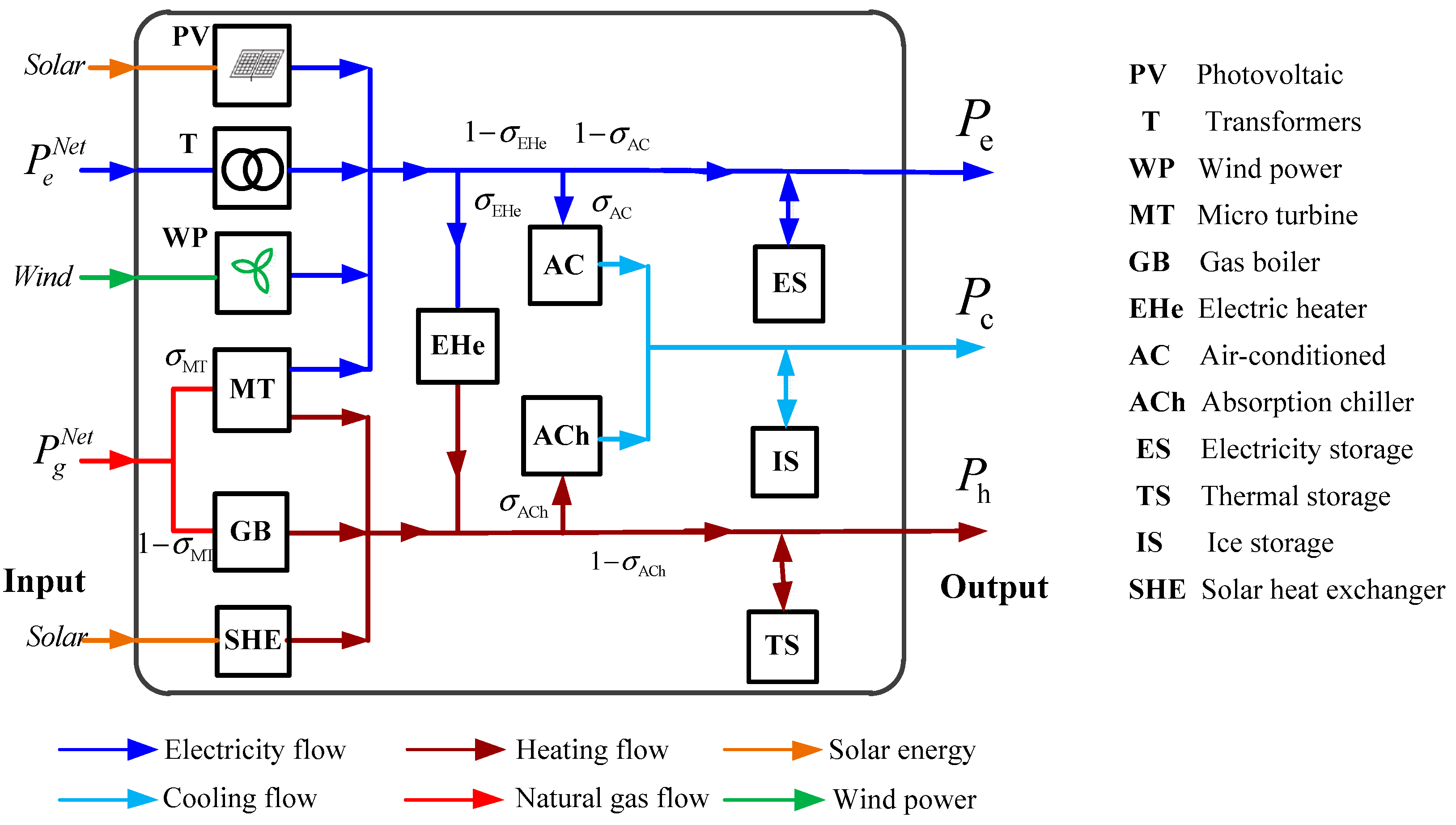
Figure 4.
Desired Energy Hub (EH) for structural and operational optimization.
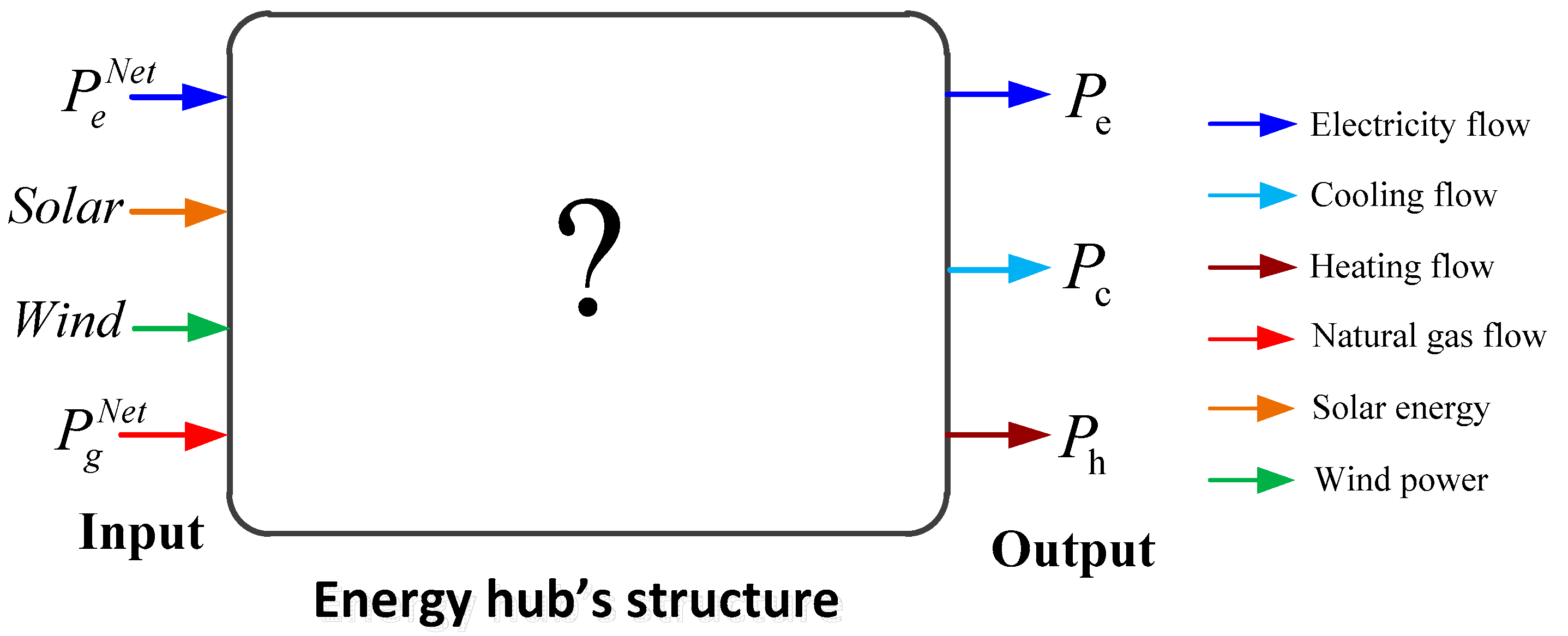
Figure 5.
Available energy converter and storage elements for the desired hub.

Figure 6.
Electrical, heat, and cooling demand in a sample day.

Figure 7.
Electricity and gas spot-prices.

Figure 8.
Output power characteristics of PV, PW, and SHE in a sample day.

Figure 9.
The process of solving the problem using GAMS. ESS: energy storage system; GAMS: General Algebraic Modeling System.
Figure 9.
The process of solving the problem using GAMS. ESS: energy storage system; GAMS: General Algebraic Modeling System.

Figure 10.
The optimal structure of the EH model.

Figure 11.
The input electricity and natural gas (Cases 1, 44, and 144).
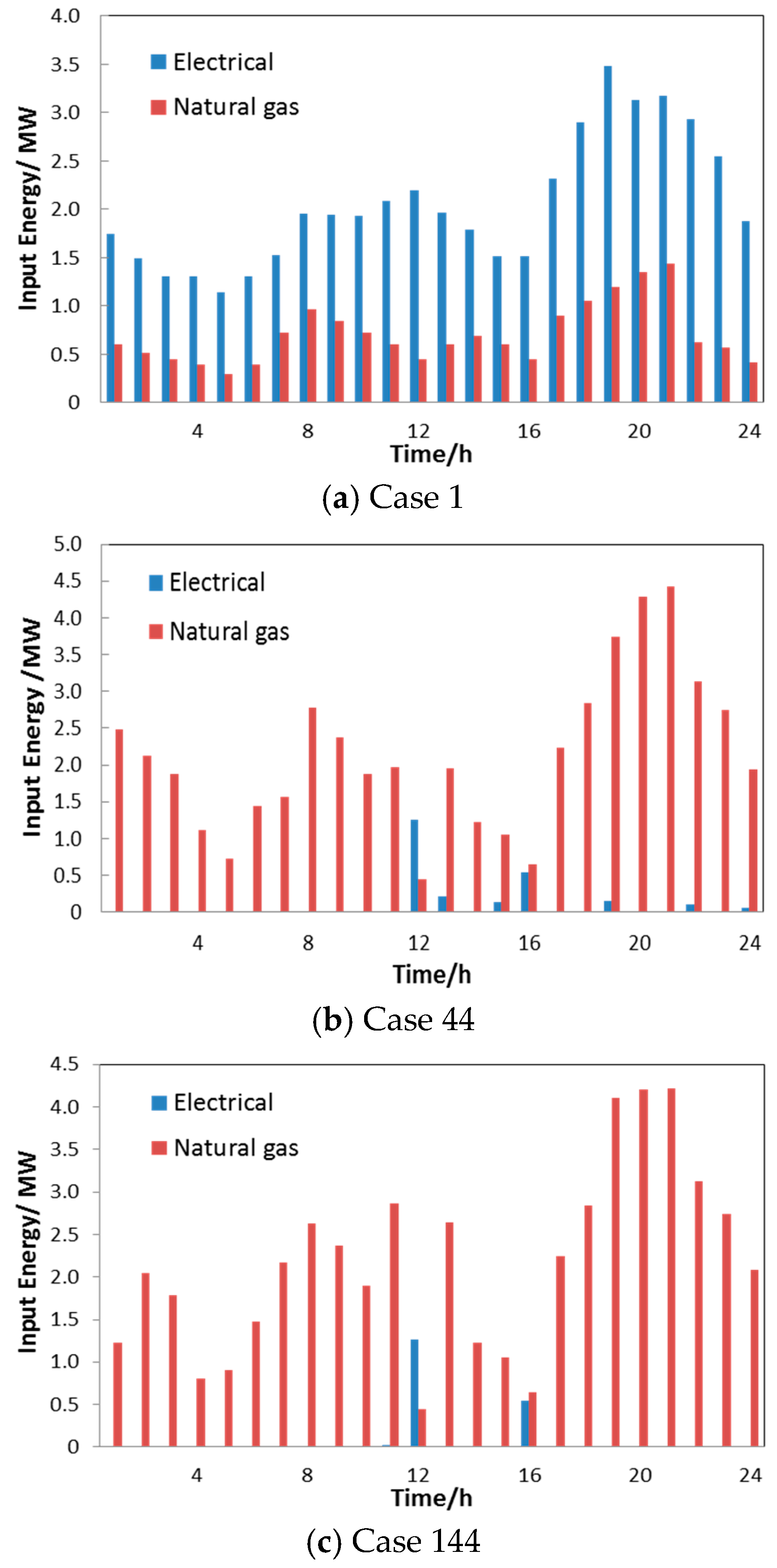
Figure 12.
Charging/discharging of energy storage devices (Cases 44 and 144).
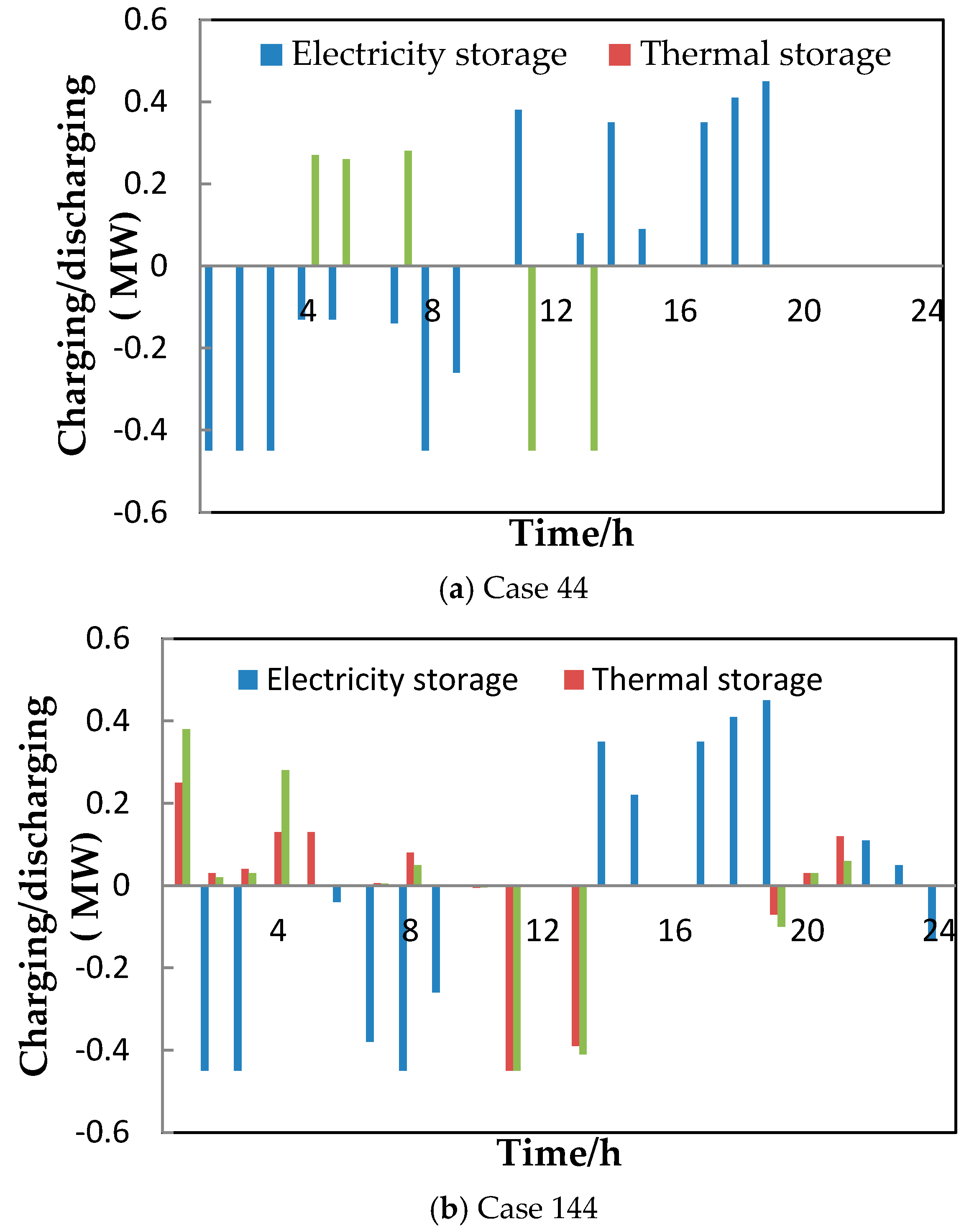
Table 1.
Parameters for Energy Storage Devices.
| 0.45 (MW) | 0.45 (MW) | 0.05 (MW) | 4.2 MWh | 0.02 | 0.93 |
| 0.45 (MW) | 0.45 (MW) | 0.05 (MW) | 4.2 MWh | 0.05 MW | 0.96 |
| 0.45 (MW) | 0.45 (MW) | 0.05 (MW) | 4.2 MWh | 0.9 | 0.95 |
Table 2.
Parameters for MT, EHe, GB, ACh, and Transformer Devices.
| 0.95 | 0.4 | 0.9 | 0.5 |
| 0.9 | 0.88 | 5 MW | 5 MW |
Table 3.
The optimal operating structure corresponding to the value of binary variables.
| Binary Variables | The Optimal Operating Structure (Case 44) | The Highest Operating Cost Scenario (Case 1) | The Full Structure Scenario (Case 144) |
|---|---|---|---|
| 1 | 1 | 1 | |
| 1 | 1 | 1 | |
| 1 | 1 | 1 | |
| 0 | 0 | 1 | |
| 1 | 1 | 1 | |
| 1 | 0 | 1 | |
| 1 | 0 | 1 | |
| 1 | 0 | 1 | |
| 1 | 0 | 1 | |
| 1 | 0 | 1 | |
| 0 | 0 | 1 | |
| 1 | 0 | 1 | |
| Total cost ($/day) | 2968 | 5136 | 2975 |
Table 4.
Economic Efficiency Data
| Calculation Results | CASE 1 | CASE 44 | ΔC |
|---|---|---|---|
| Total energy costs ($/day) | 5136 | 2968 | 2168 |
© 2018 by the authors. Licensee MDPI, Basel, Switzerland. This article is an open access article distributed under the terms and conditions of the Creative Commons Attribution (CC BY) license (http://creativecommons.org/licenses/by/4.0/).
Share and Cite
MDPI and ACS Style
Ha, T.T.; Zhang, Y.; Hao, J.; Thang, V.V.; Li, C.; Cai, Z. Energy Hub’s Structural and Operational Optimization for Minimal Energy Usage Costs in Energy Systems. Energies 2018, 11, 707. https://doi.org/10.3390/en11040707
AMA Style
Ha TT, Zhang Y, Hao J, Thang VV, Li C, Cai Z. Energy Hub’s Structural and Operational Optimization for Minimal Energy Usage Costs in Energy Systems. Energies. 2018; 11(4):707. https://doi.org/10.3390/en11040707
Chicago/Turabian StyleHa, Thanh Tung, Yongjun Zhang, Jinbao Hao, V. V. Thang, Canbing Li, and Zexiang Cai. 2018. "Energy Hub’s Structural and Operational Optimization for Minimal Energy Usage Costs in Energy Systems" Energies 11, no. 4: 707. https://doi.org/10.3390/en11040707
Note that from the first issue of 2016, this journal uses article numbers instead of page numbers. See further details here.