Development of a Variable Water Flow Rate Control Method for the Circulation Pump in a Geothermal Heat Pump System

1
Department of Architectural Engineering, Graduate School of Yeungnam University, 280 Daehak-Ro, Gyeongsan, Gyeongbuk 38541, Korea
2
School of Architecture, Yeungnam University, 280 Daehak-Ro, Gyeongsan, Gyeongbuk 38541, Korea
*
Author to whom correspondence should be addressed.
Energies 2018, 11(4), 718; https://doi.org/10.3390/en11040718
Submission received: 28 February 2018
/
Revised: 10 March 2018
/
Accepted: 13 March 2018
/
Published: 22 March 2018
Abstract
:This study assessed a variable flow rate control method for a circulation pump based on the geothermal water temperature difference in a geothermal heat pump system. As interest in energy conservation and efficient use is increasing around the world, the development and use of renewable energy is increasing and various related studies are currently underway. Among the renewable energy systems, the interest in geothermal energy system is high because of its efficient year-round operation. Geothermal heat pump system installations have increased in number, but the systems operate inefficiently. Generally in Korea, geothermal heat pump system operates under partial load conditions, but the circulation pump operates at constant speed and supplies a constant flow rate. Therefore, this study examined the operation of the current problems of a geothermal heat pump system. A variable flow rate control method of the circulation pump is proposed to improve the efficiency of the geothermal heat pump system and save energy during the cooling operation. As a result, the total energy consumption was reduced by 57,017 kW compared to the existing flow rate control method and the energy consumption of the circulation pump system was reduced by 35,209 kW.
1. Introduction
With the increasing interest in energy conservation and the efficient use of energy around the world, the need for the development and use of new and renewable energy sources has increased rapidly, and related research and applications have been actively conducted. Among the new and renewable energy sources, systems using geothermal sources are attracting considerable attention. This is because while there is a lack of continuity of heat sources for systems using other heat sources, a stable supply of heat and efficient operation throughout the year are possible if geothermal energy is used as a heat source. Although geothermal energy shows excellent efficiency as a heat source for cooling and heating, geothermal heat pump systems have mainly been installed in public buildings, and systems with low capacity have mostly been installed because of the high initial investment costs and difficulty in construction. On the other hand, since regulations on new and renewable energy installation institutions for public buildings were implemented in Korea in 2004, installations in non-public buildings and public institutions have also increased.
While the installation of geothermal heat pump systems is increasing, the systems are not being operated efficiently. This results in a waste of energy due to the inefficient utilization after the installation of systems with more than the necessary capacity in conformity with the standards set forth in the relevant laws and regulations regarding the mandatory supply and installation. The geothermal heat pump system is generally responsible for a number of indoor units and is operated mostly under partial load conditions. On the other hand, most of the geothermal circulation pumps in geothermal heat pump systems are operated at a constant rate and a constant flow rate is supplied continuously, regardless of the load. As a result, the performance of the geothermal heat pump system is decreased. This paper proposes a variable water flow rate control method for a geothermal circulation pump to improve the efficiency of the geothermal heat pump system.
As the interest in geothermal heat pump systems has increased, various studies have been conducted on these systems [1,2,3,4,5,6,7,8]. Moreover, there have been several studies related to the cooling and heating performance evaluation of geothermal heat pump systems. Sohn [9] and Kwon [10] assumed that a geothermal heat pump system was installed in an actual commercial office building instead of a conventional heating and cooling system, and analyzed the cooling and heating performance of the geothermal system according to the time of the year through a simulation. They compared the actual energy consumption of the existing system and the estimated energy consumption of the geothermal system [9]. Nam conducted a system performance analysis through dynamic energy simulation of the heat pump system using solar and geothermal energy [10]. Hwang et al. [11] and Ozgener [12,13] conducted research to verify the feasibility of a hybrid system and the performance of the system through the experimental performance evaluation of the actual system.
In addition, various studies have been conducted to improve the performance of geothermal heat pump systems. Studies of the efficiency and optimal design of the geothermal heat exchanger, including studies by Park [14] and Lee [15], are being conducted. Park measured the changes in the ground temperature according to the burial depth for a geothermal heat pump system actually installed in a residential building, and analyzed the performance of the heat exchanger and cooling performance of the heat pump according to the ground temperature variation [14]. Lee derived the optimal design method through an analysis of the design load and the actual usage data of the geothermal system with the main focus on electricity consumption and heating and cooling energy consumption of the building studied [15].
Many studies have been conducted on the performance improvement of the heat pump system through integrated design with other heat source systems and complex operation in relation to the cause of the decrease in the efficiency of the geothermal heat pump system. In a study by Girard, a performance analysis was conducted by simulating a hybrid operation geothermal heat pump system and a general geothermal heat pump system to improve the performance of the hybrid operation of solar and geothermal heat pump systems [16]. The problems of the operation of a geothermal source heat pump system were derived through an investigation of the building where the system was installed, a complex operation method with an absorption chiller-heater was then proposed to increase the share ratio of the geothermal heat pump system, and the method was evaluated through a simulation [17]. Jung proposed an operation method of adding the coefficient of the performance to the operation points, which makes it possible to maximize the equipment efficiency of the geothermal heat pump system and take into account the equipment performance. Jung also suggested an operation method to maximize the use of the geothermal heat pump system through an integrated design with an existing heat source and improve energy efficiency, and conducted an evaluation of the method through a simulation [18].
Although many studies on efficient design methods of an underground heat exchanger are being conducted, there has been a lack of research on the variable flow rate control of geothermal water and the operations utilizing it. Jung analyzed the pump energy consumption of a geothermal heat pump system according to the changes in the geothermal water flow rate of the geothermal heat pump system and the COP (Coefficient of Performance) of the heat pump unit [19]. Song reported a variable flow rate control method of the geothermal circulation pump using the source side temperature difference of the geothermal heat pump and validated the application of the method through an empirical study [20]. This study demonstrated the performance of the variable flow rate control method through a replacement of the circulation pump during the heating operation and verified the effectiveness for COP improvement of the geothermal heat pump system. On the other hand, the energy-saving effect and cooling performance have not been evaluated.
Therefore, this paper suggests a variable water flow rate control method of a geothermal circulation pump to improve the efficiency and energy savings of the geothermal heat pump system during the cooling operation. For this purpose, the proposed variable water flow rate control method was applied to the target building using the TRNSYS (Transient System Simulation Tool) program, and comparative analysis with the existing operation method was performed. The analyses of the indoor thermal environment, energy consumption of the geothermal circulation pump, and energy consumption of the geothermal heat pump system was then performed.
2. Theoretical Analysis
2.1. Building Information
The target building is a mixed-use building consisting of cultural and meeting facilities, business facilities, retail facilities, and neighborhood living facilities located in Daegu, Korea. Figure 1 shows the exterior of the building and Table 1 provides basic information of the building. The total floor area was 49,667 m2 and the air conditioned area was 33,744 m2. It consists of two basement floors and nine above ground floors.
For the development and evaluation of a variable flow rate control algorithm for the efficient operation of a geothermal heat pump system, a target building with an actual geothermal heat pump system was selected and the operation status was investigated. The geothermal heat pump system, ice storage system, and condensing boiler were being used as the heat source system of the target building. The geothermal heat pump system had a total capacity of 320 RT and seven units were operated. A total of 8 geothermal circulation pumps, including one spare pump, were used. Table 2 and Table 3 show the basic information of the geothermal heat pump and a summary of the circulation pump features, respectively.
The geothermal heat pump was separated from other heat source systems and used for air-condition some parts of the building. The heat source water produced was supplied to AHU (Air Handling Unit) and FCU (Fan Coil Unit) to air-condition each area for which the geothermal heat pump is used. The geothermal heat pump system meets the heating and cooling loads of the cultural and meeting facilities on the first basement and the business facilities on the third and fourth floors, which account for approximately 26% of the total heating and cooling loads, and they are responsible for three air conditioners.
The geothermal heat pump system is controlled by the operating number control based on the cold and hot water supply temperatures. The hot and cold water produced by the geothermal heat pump system is returned after heat exchange in the air conditioner coil. The operating number control of the geothermal heat pump system is performed using the temperature difference of the hot and cold water between the inlet and outlet. The geothermal circulation pump is operated to supply a set flow rate continuously regardless of the load. In this operation method, even if the load is lowered, the system operates continuously to maintain the set temperature. In addition, the geothermal circulation pump supplies a constant flow rate even under partial load conditions, so a certain amount of power of the pump is consumed continuously and an energy waste problem arises.
2.2. Theoretical Analysis of the Relationship between Water Flow Rate and COP
The geothermal heat pump system COP is affected by the consumption power of the geothermal circulation pump and the power of the compressor. The following equation and p-h diagram were used to check the variable water flow rate control of the circulation pump in the geothermal heat pump system to reduce the energy consumption and improve the system performance. When a heat exchange is performed in a geothermal heat pump, the average temperature difference can be obtained, as shown in Equation (1), and the quantity of heat using the total heat transfer coefficient is given by Equation (2):
Ignoring any heat transfer between the exchanger and its surroundings and the changes in potential and kinetic energy, and assuming that the specific heat is constant, Equations (3) and (4) can then be obtained by applying a total energy balance of the hot and cold fluids:
Equations (5) and (6) were obtained by applying an energy balance to each micro element in a heat exchanger, where heat exchange occurs only between the high temperature fluid and the low temperature fluid because the surrounding is insulated:
By integrating these equations over the heat exchanger, the total energy balance can be obtained using Equations (4), and the heat transfer through surface area dA can also be expressed as Equation (7):
Equation (8) can be obtained by substituting Equations (4) and (5) into the derivative of :
Equation (9) can be obtained by substituting dq in Equation (7) and integrating the heat exchanger as a whole. Equation (10) can be derived by substituting and in Equation (4):
In a parallel-flow heat exchanger, the heat transfer rate can be expressed as Equation (13) using Equations (11) and (12):
Comparing Equations (2) and (13), the appropriate mean temperature difference is the logarithmic mean temperature difference. Therefore, the heat flow rate and mean temperature difference can be calculated using Equations (14) and (15):
Through this relationship, the flow rate of geothermal water can be obtained, as shown in Equation (16):
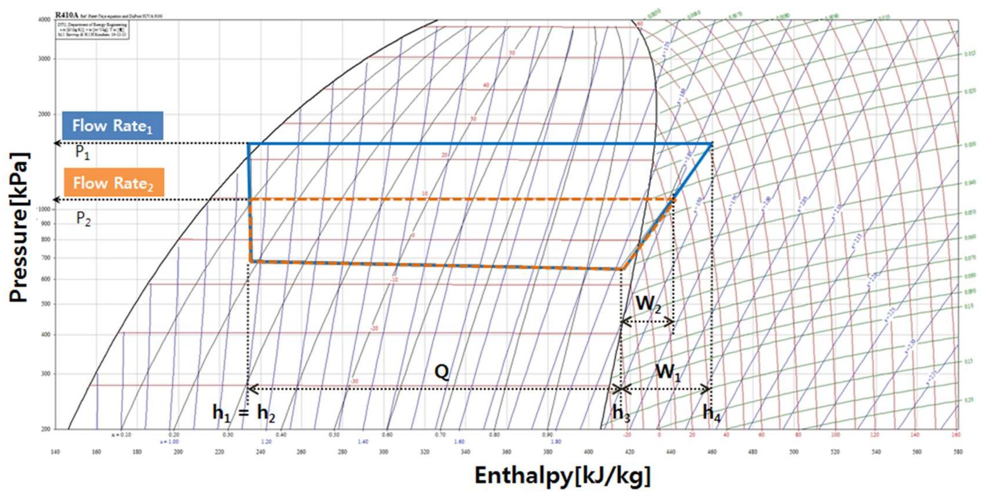
Figure 2 presents the p-h diagram with varying flow rates at the same indoor load in the target building. The system COP can be obtained using the values at each point of the heat pump cycle shown in Figure 2, as shown in Equation (17): [21]
The geothermal heat pump system COP was 3.3 when the flow rate of the circulation pump was 25 LPM (flow Rate1), and geothermal heat pump system COP was 5.4 when flow rate of circulation pump was 15 LPM (flow Rate2). This shows that with decreasing flow rate, the pressure decreases, the power consumption of the compressors decreases and the system COP increases. This means that the variable water flow rate control of the geothermal heat pump system reduces the energy consumption of the compressors and improves the system COP.
3. Development of the Variable Water Flow Rate Control Method of a Circulation Pump
3.1. Constant Water Flow Rate Control of a Circulation Pump
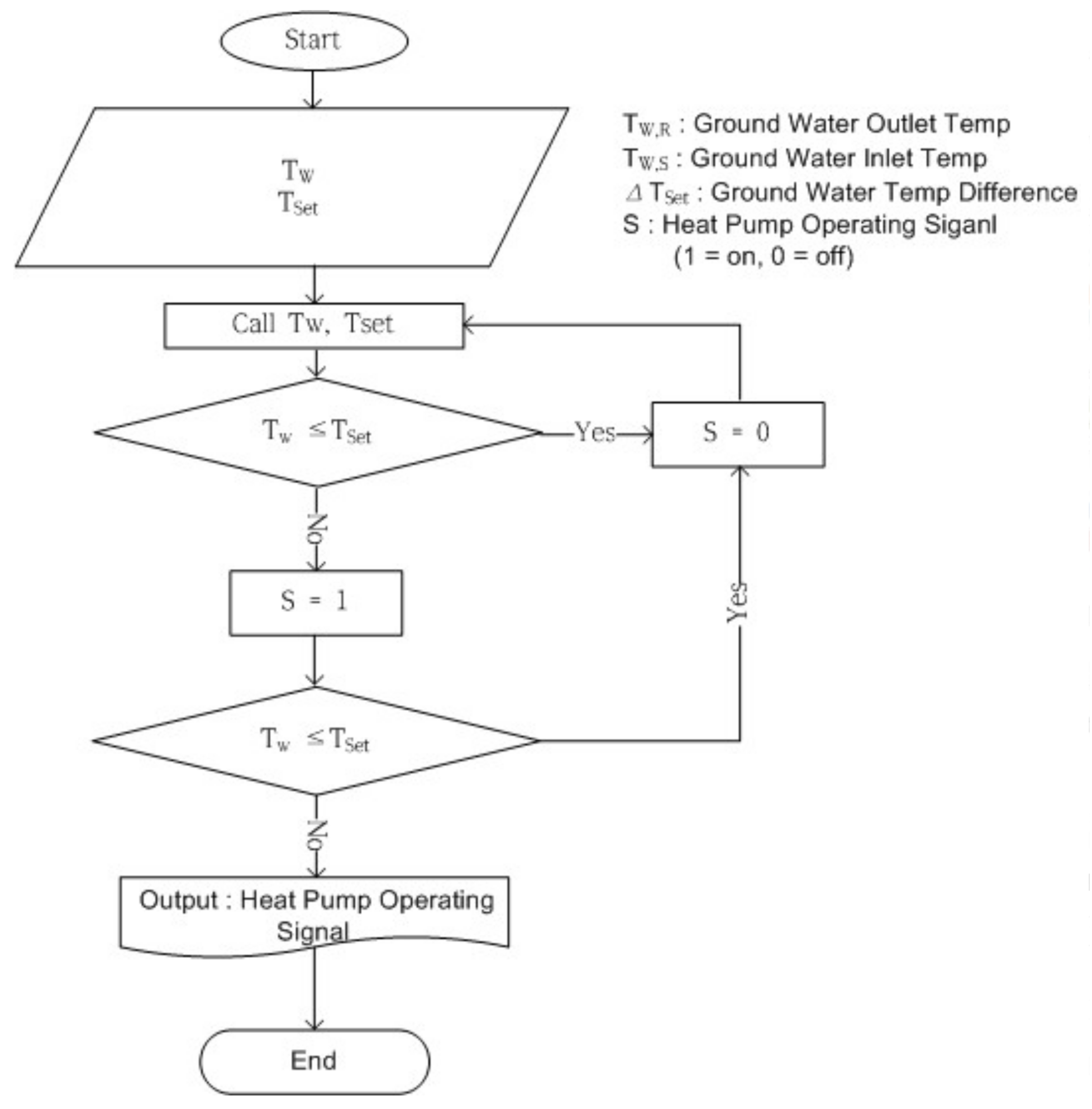
In general, when a heat pump, which is responsible for only a part of the load of the entire building, is operated, the efficiency of the entire system is reduced when a constant-speed pump is used. A constant water flow rate control method was the existing operation method of the target building and this method was to supply a constant water flow rate. According to the set cold and hot water temperatures, the system is operated if the upper limit of the set temperature is reached, and the operation of the heat pump is stopped if the temperatures of the cold and hot water outlets reach the set lower limit. Figure 3 shows the existing constant water flow rate control algorithm.
The flow rate of geothermal water and the heat transfer coefficient using the inlet-outlet temperature difference can be calculated using Equation (18). The geothermal water flow rate can be calculated using Equation (19), and the COP of the geothermal heat pump system can be determined using Equation (17). In constant flow rate control, the flow rate is provided regularly and the difference in temperature varies according to the load:
3.2. Reset Water Flow Rate for Max COP
Load calculations from constant flow rate control and variable flow rate control can be expressed as Equation (20); therefore, the flow rates from variable control may be written as Equation (21):
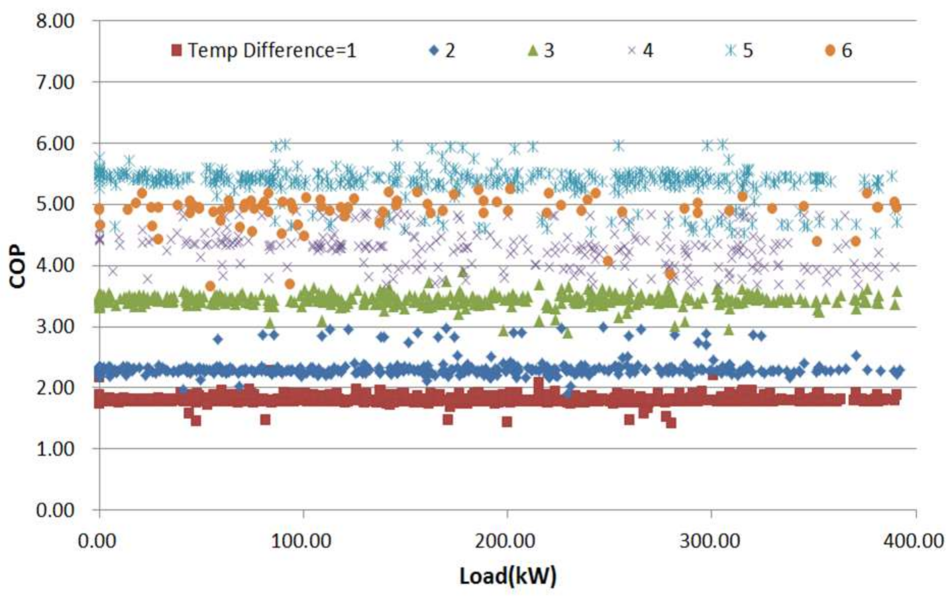
Equation (21) was used to calculate the flow rate to a variable water flow control to improve the system efficiency and reduce energy. If the flow rate is controlled using the temperature difference that can lead to the maximum COP of the total system of the geothermal heat pump, it can operate the system with less energy and achieve high efficiency. The relationship between the COP and the variations in load conditions were analyzed to determine the flow rates, indicating the maximum COP. Figure 4 presents the analysis results.
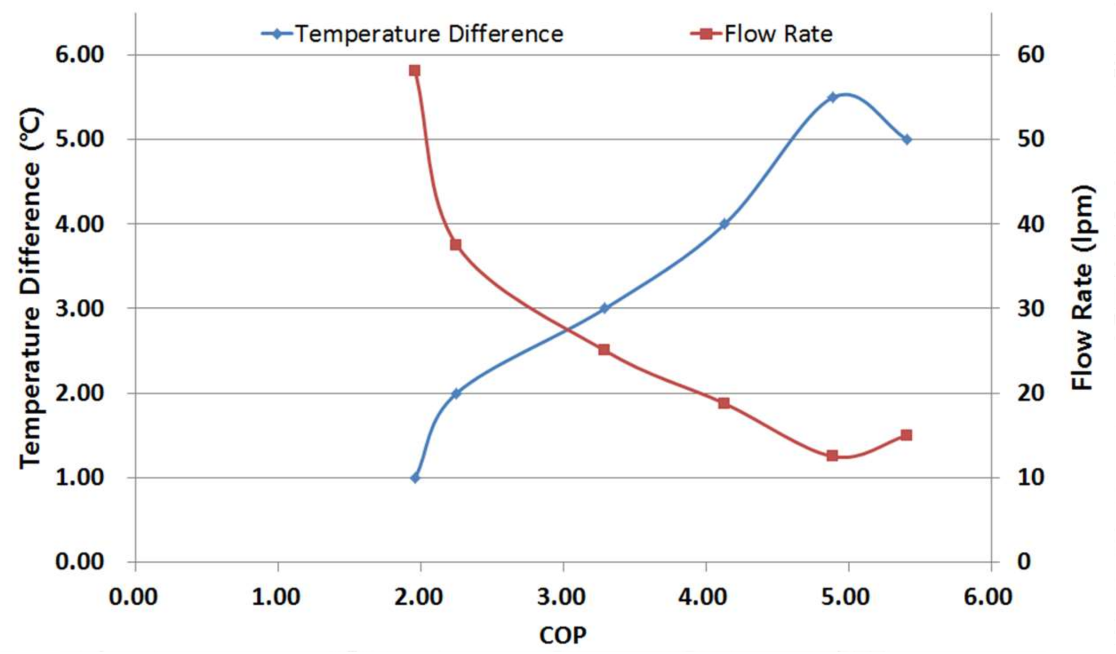
Figure 5 presents the results of COP analysis according to the temperature difference and flow rate. At a lower flow rate and higher temperature difference, the COP showed an improvement of the COP; the highest COP was observed when the flow rate was 13 LPM and the difference in temperature was approximately 5 °C. If the flow rate decreases since then it is likely that the COP shows a decrease. The COP improvement effects of the geothermal heat pump systems can be verified by controlling the variable flow rate between the designed maximum flow rates and the smallest flow rate to the maximum COP.
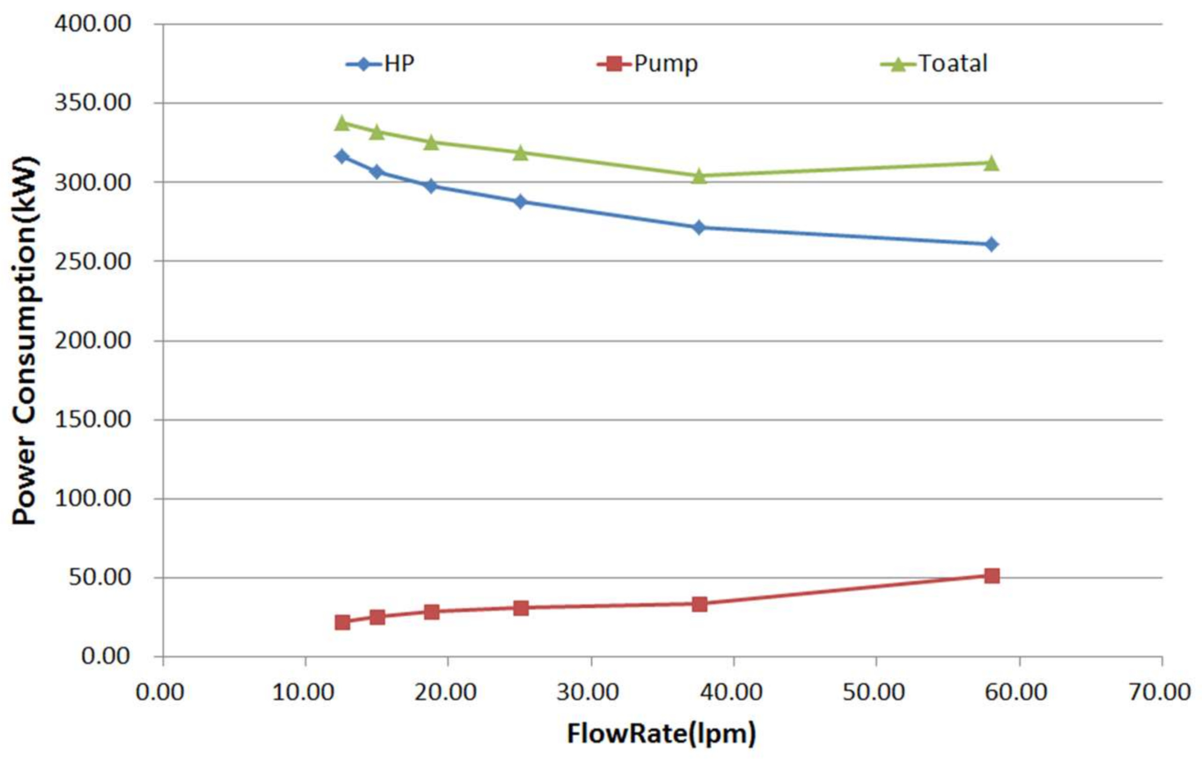
As shown in Figure 6, the energy consumption of the geothermal heat pump decreases with increasing flow rate, but the COP is decreased as the energy consumption of the geothermal circulation pump increases considerably. Therefore, the maximum efficiency is achieved by variable flow rate control method of controlling the flow rate so that a geothermal water temperature difference of 5 °C can be maintained. Therefore, this paper proposes a variable flow rate control method by maintaining a geothermal water temperature difference of 5 °C.
3.3. Proposed Variable Water Flow Rate Control Method
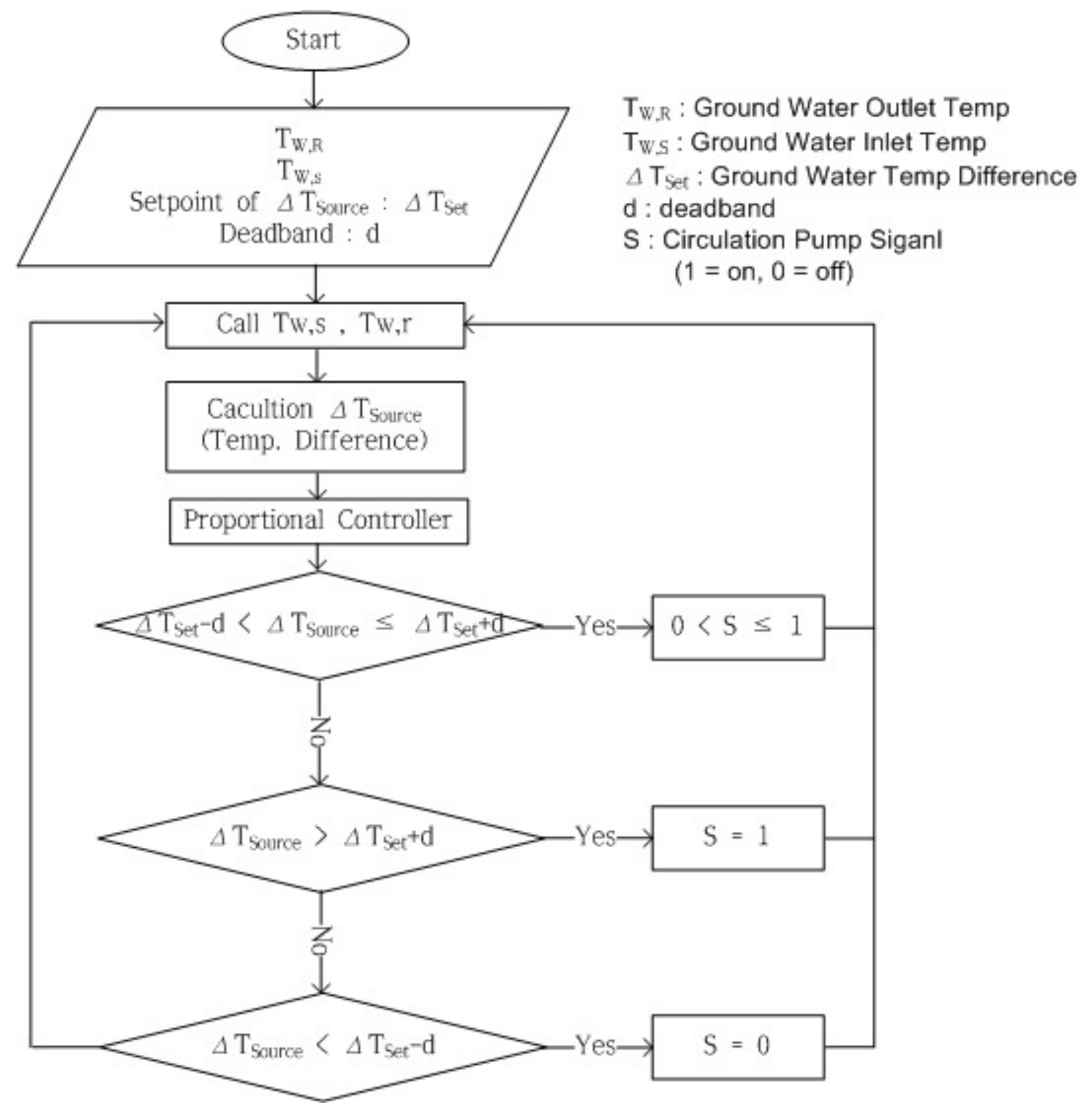
As shown in Figure 7, after calculating the temperature difference between the inlet and outlet by measuring the geothermal water temperature of the inlet and outlet of the geothermal heat pump, the calculated temperature difference was compared with the set temperature difference, and the system was controlled proportionally to reach the set temperature difference. Several cases are considered:
- ①
- If the temperature difference between the inlet and outlet of the heat pump is within the range of the set temperature difference
If the temperature difference between the inlet and outlet of the heat pump is within the range of the set temperature difference (Tset − d < ∆Tsource ≤ Tset + d), the supply flow rate of the pump is determined proportionally by the signal value of the proportional control (0 < Singal ≤ 1).
- ②
- If the temperature difference is larger than the set temperature difference (∆Tsource > Tset + d)
If the temperature difference is larger than the set temperature difference (∆Tsource > Tset + d), 100% of the design flow rate of the circulation pump is provided.
- ③
- If it is smaller than the set temperature difference
If it is smaller than the set temperature difference (Tset − d > ∆Tsource), the operation of the circulation pump is stopped.
4. Modeling Dynamic Simulation
Transient Systems Simulations (TRNSYS) is a detailed building energy analysis program. The program was written for long-term cost reduction verification through a dynamic simulation of the solar thermal system developed by researchers at the University of Wisconsin in 1975, and is currently being used as the energy simulation and building energy analysis program involving HVAC (Heating, Ventilation, Air Conditioning) equipment, cogeneration system, and control system, including new and renewable energy in Europe and other countries around the world [22,23,24].
TRNSYS is a program suitable for detailed analysis of the systems that change over time. When the TRNSYS program is used, the user performs the simulation by connecting the components to each other. Components are being developed around the world and can be added after coding using the FORTRAN language. In this respect, TRNSYS has an advantage in that it is convenient when the user selects the system. The modeling of the target building was conducted using the Google Sketch Up program, as shown in Figure 8.
Table 4 lists the indoor load, temperature, and humidity conditions of the representative room used in the simulation. The following was performed to implement the geothermal heat pump system: the Type 927 water to water heat pump was used for the geothermal heat pump; the vertical heat exchanger Type 557a was used for the geothermal heat exchanger; and Type 3b was used for the geothermal circulation pump and cold water supply pump.
The existing operation method of the geothermal heat pump system of the target building is a constant water flow rate control based on the cold and hot water supply temperatures. This was selected as CASE 1, and the method reflecting the variable water flow rate control method of geothermal water circulation to improve the efficiency of the geothermal heat pump system was selected as CASE 2. Table 5 summarizes the simulation CASE.
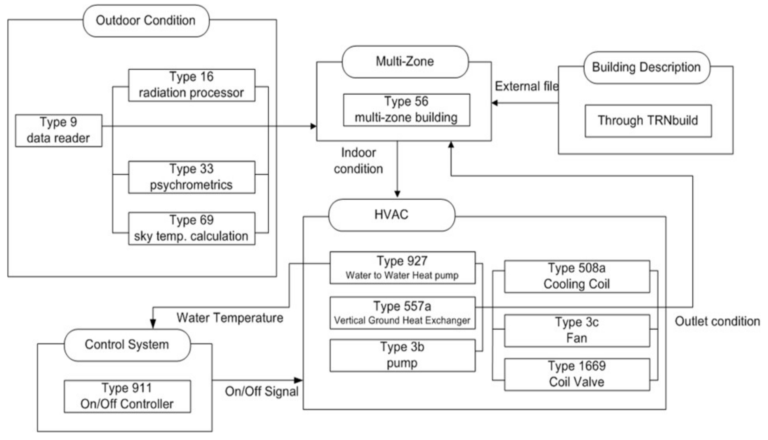
- (1)
- Existing constant water flow rate control method (CASE 1)
Figure 9 shows the simulation flow diagram of the operating number control according to the set temperature, which is the existing operation method of the target building. The water-to-water type heat pump Type 927 was used for the heat pump and the vertical heat exchanger Type 557a was used for the underground heat exchanger. Type 3b was used for the underground circulation pump and cold water supply pump. To control the set temperature of each geothermal heat pump, the set temperature of the heat pump was used as the controller input value and the on/off controller Type 911 was used.
- (2)
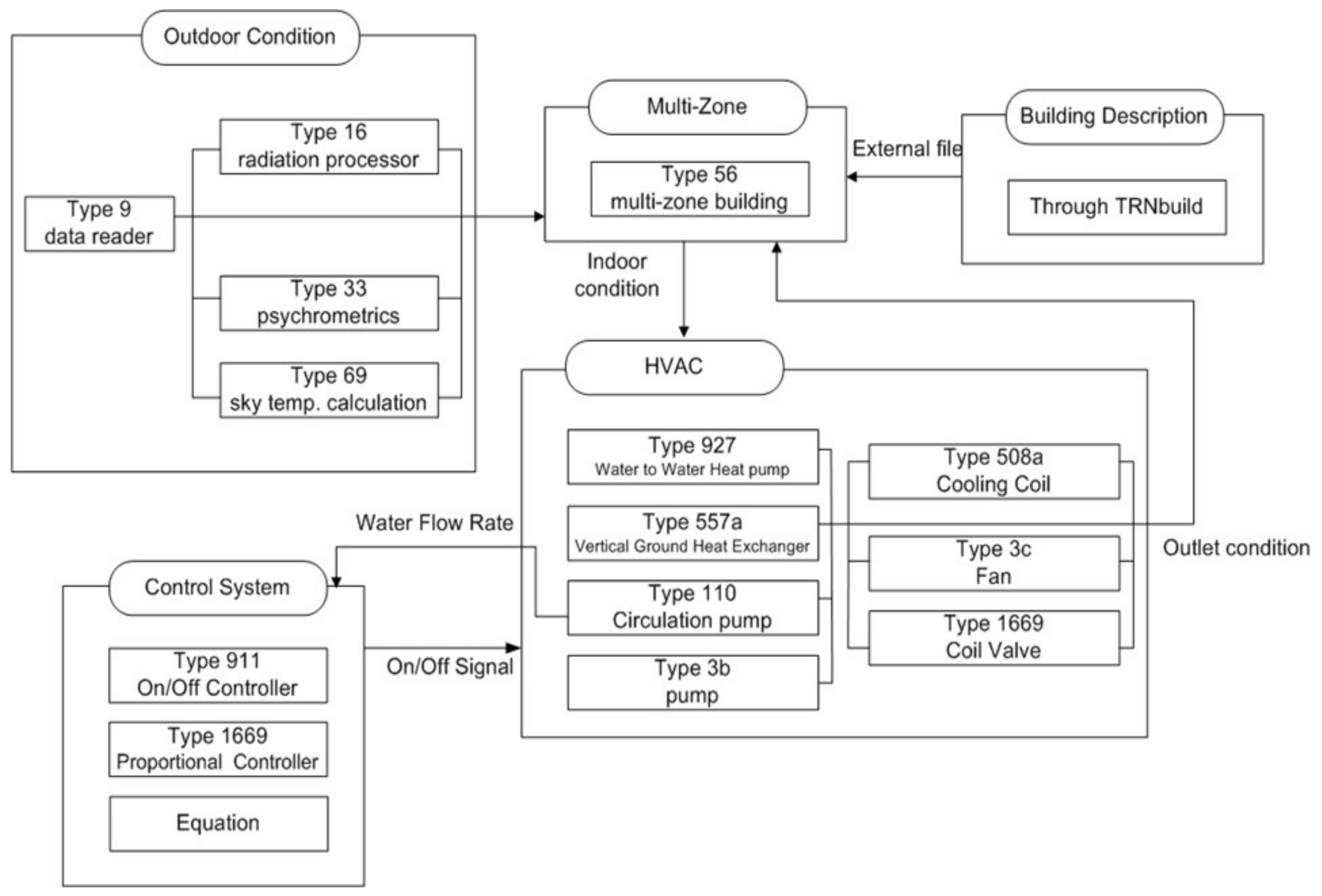
- Proposed variable water flow rate control method (CASE 2)
For the variable water flow rate control method, the geothermal water temperature difference between the inlet and outlet was changed to the control point. The proportional controller Type 1669 was used to control the flow rate based on the circulation pump temperature difference. The equations were used to calculate the temperature difference and reflect the indoor temperature. The circulation pump was implemented using the variable speed pump Type 110 to analyze geothermal water flow rate control and changes in the pump energy consumption depending on the change in flow rate. Figure 10 shows the variable water flow rate control method.
5. Results and Discussion
The conventional flow rate control method of the geothermal heat pump system of the target building provides a continuous supply at a constant flow rate regardless of the load by installing a constant speed pump. This method was selected as CASE 1. To improve the efficiency of the geothermal heat pump system, the variable geothermal water flow rate control method was applied, and it was selected as CASE 2. Table 6 presents a summary of the simulation CASE.
- (1)
- Indoor Thermal Environment
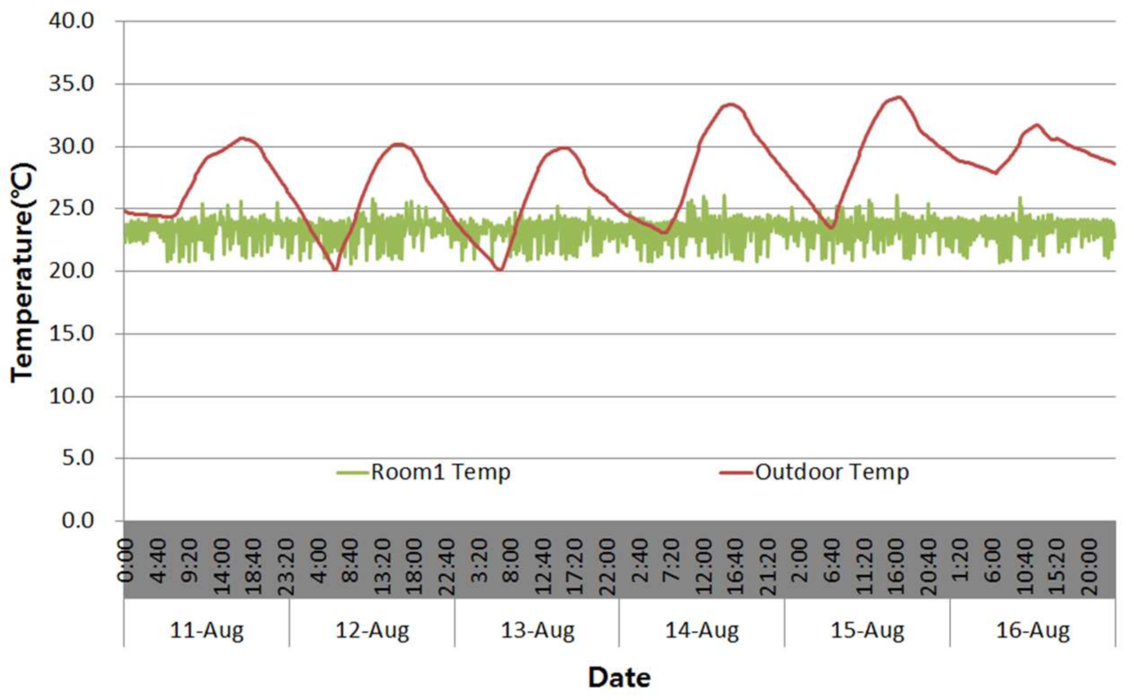
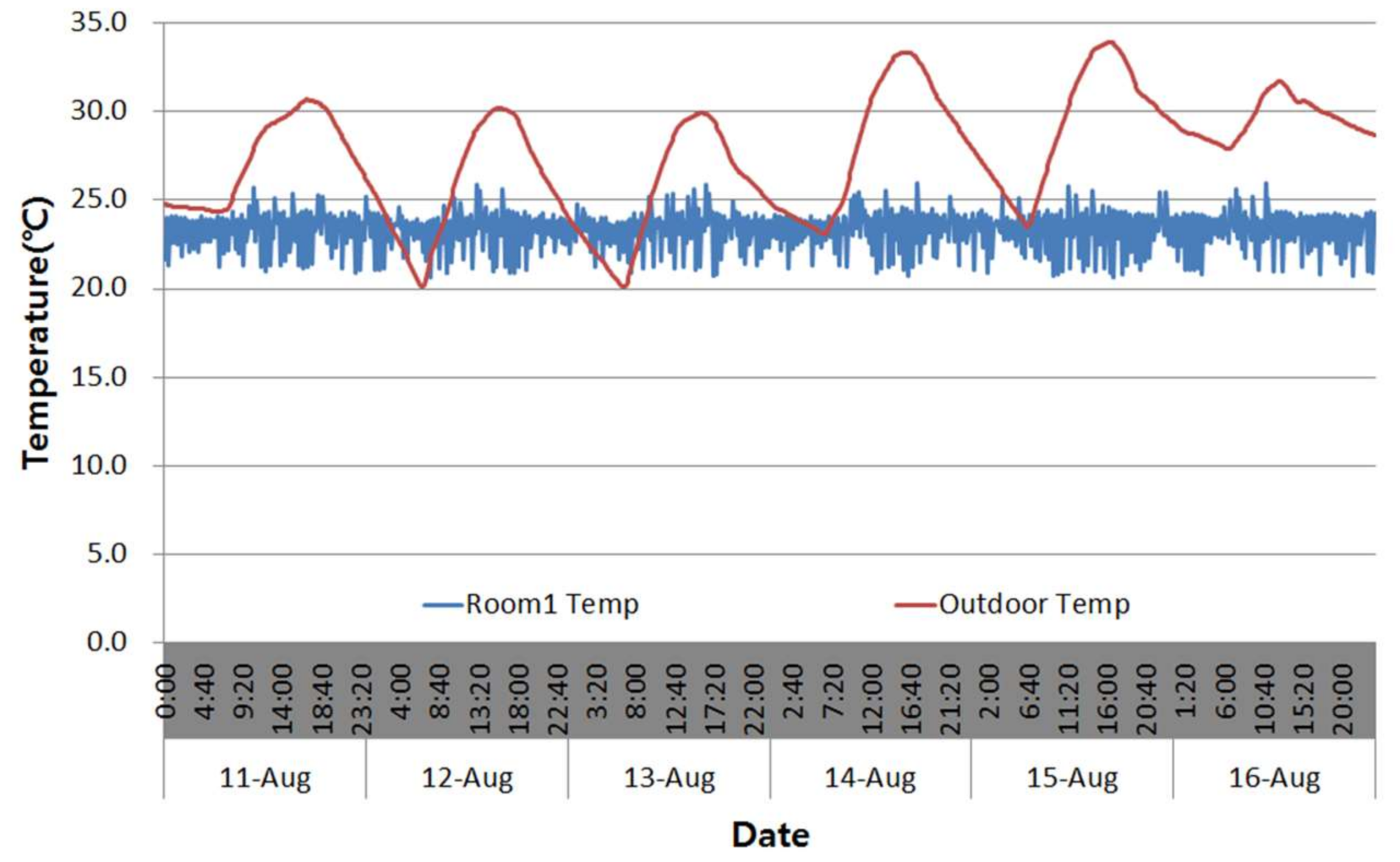
The indoor thermal environment when the geothermal water flow rate control of the geothermal heat pump system was applied was analyzed. Figure 11 and Figure 12 show the changes in the indoor temperature according to the CASE. The room temperature was set to 24 °C (±0.5 °C), which the temperature was maintained within the set temperature variation in CASE 1, which was the existing method, and CASE 2, where geothermal water flow rate control was applied.
- (2)
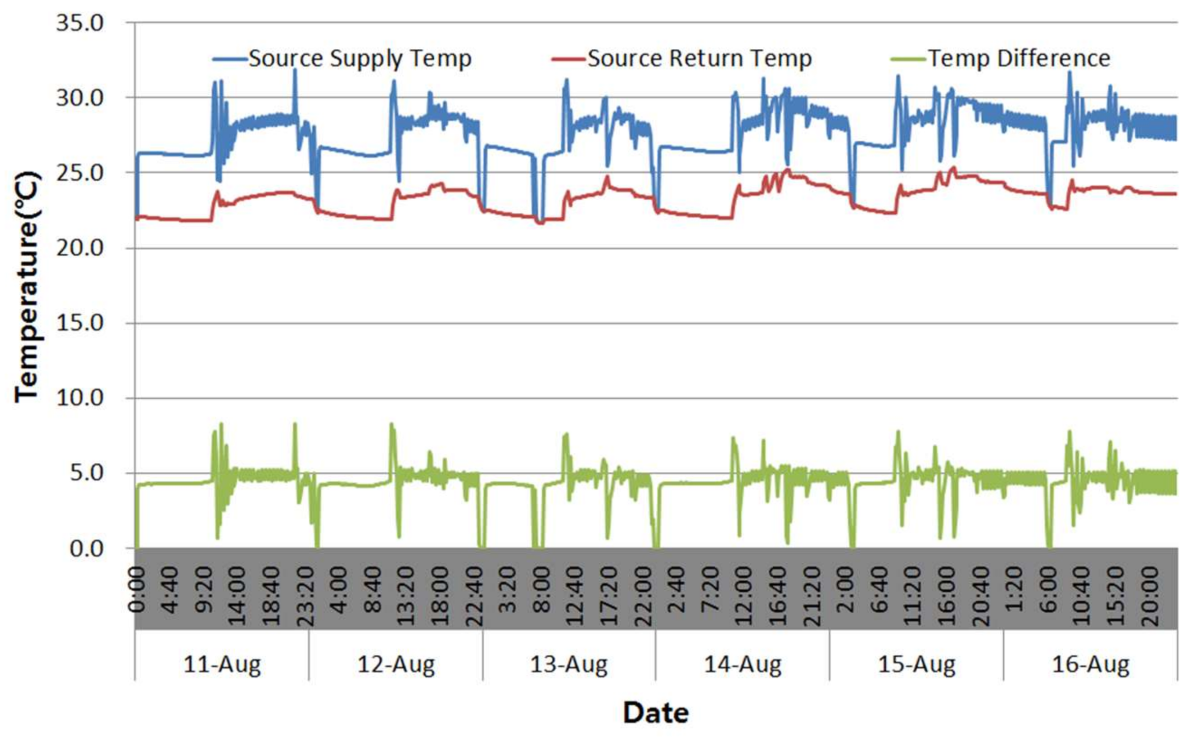
- Geothermal Side Temperature
To analyze the geothermal water temperatures of the inlet and outlet of the geothermal heat pump, Figure 13 and Figure 14 present the changes in the geothermal water temperatures of the inlet and outlet. In CASE 1, the average temperature difference was approximately 1.7 °C. In CASE 2, because the flow rate was controlled by adjusting the geothermal water temperature difference so that it would be 5 °C (±0.5 °C), an average of approximately 4.3 °C was relatively stable.
- (3)
- Water Flow rate and Energy Consumption
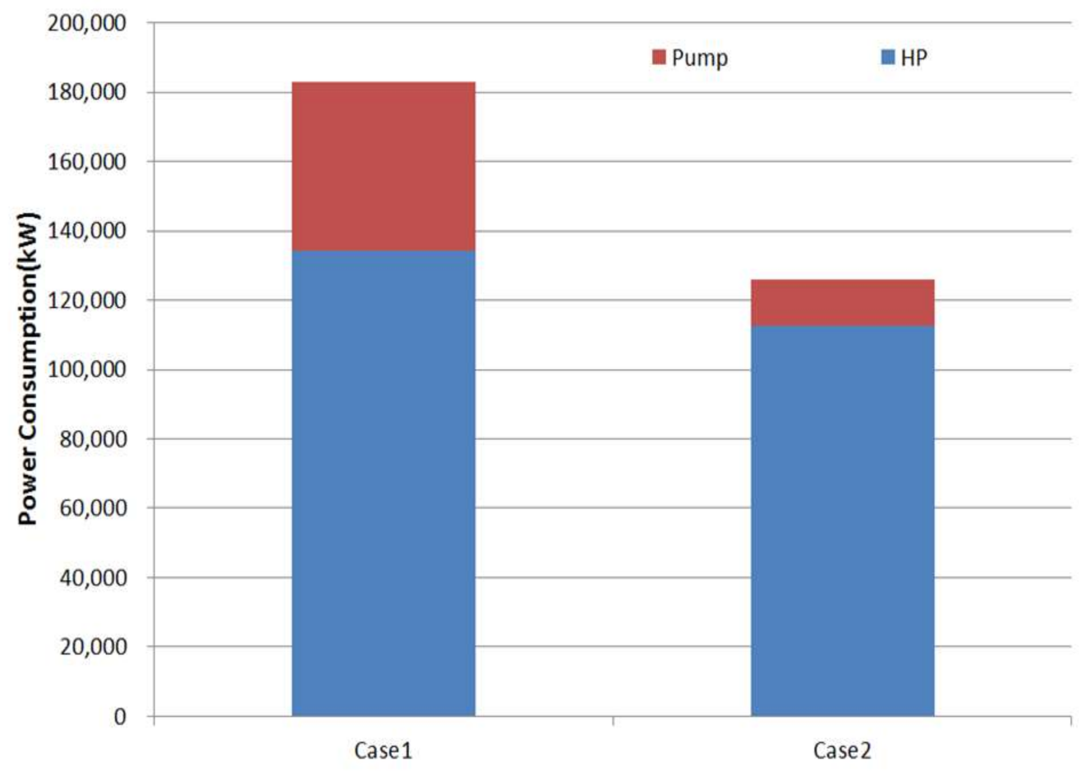
Figure 15 shows the geothermal water flow rate for each case. The flow rate in the variable flow rate control method is approximately 70% lower than the constant water flow rate method. Figure 16 shows the heat pump and circulation pump energy consumption for each case to analyze the energy consumption when applying the geothermal water flow rate control method of the geothermal heat pump. The total energy consumption was 182,936 kW for CASE 1, in which the constant flow rate control method of the target building was used, and 125,919 kW for CASE 2, in which the geothermal circulation water flow control method was applied. The energy consumption of CASE 2 was 32% lower than CASE 1, and the energy consumption of the circulation pump is approximately 70% lower. Table 7 lists detailed energy consumption values of the heat pump and circulation pump for each case.
6. Conclusions
This study examined the operation of the current problems of geothermal heat pump system and proposed a variable water flow rate control method of the circulation pump to improve the efficiency of the geothermal heat pump system and save energy during cooling operations. The proposed operation method was compared with the existing operation method using a simulation. The results of this study can be summarized as follows:
- (1)
- After selecting the target building where the geothermal heat pump system was installed, the operation method of the heat pump system was investigated. The geothermal heat pump system of the target building was operated by on-off control according to the set temperature to adjust the load side return water temperature so that it can match the set temperature, and a constant flow rate was supplied continuously due to the constant speed pump of the geothermal circulation pump. If this operation method is used, the return water temperature of geothermal water circulation is adjusted, irrespective of the load. Therefore, unnecessary energy is consumed due to the continuous operation of the circulation pump. A variable flow rate control method of geothermal water circulation was proposed to solve this problem.
- (2)
- To control the geothermal water flow rate to reduce the energy consumption and improve the efficiency of the geothermal heat pump, this paper suggested a flow rate control method of the circulation pump by geothermal water temperature difference. An analysis of the COP according to the geothermal water temperature difference and an analysis of energy consumption of the heat pump and circulation pump according to the flow rate showed that the energy consumption was lowest and the efficiency was highest when the temperature difference was 5 °C.
- (3)
- A variable flow rate control method of the heat pump system was proposed and the proposed variable flow rate control method was evaluated by a comparison with the existing constant flow rate control method of the target building. As a result, the total energy consumption was reduced by 57,017 kW compared to the existing flow rate control method and the energy consumption of the circulation pump system was reduced by 35,209 kW, which corresponds to an approximately 70% reduction.
In this study, the flow rate control method was applied and evaluated through simulations. Therefore, there is still a need to evaluate the effect when it is applied to actual buildings. In addition, because the flow control method was applied and evaluated only in summer, it will be necessary to apply the operation method in winter. In other words, future studies should apply the proposed flow rate control method to actual buildings and apply and evaluate it in winter to enable efficient control of the geothermal heat pump system.
Acknowledgments
This work was supported by the 2016 Yeungnam University Research Grant (216A380095).
Author Contributions
All authors contributed to this work. Ji-Hyun Shin performed the result analysis and wrote the major part of this article. Young-Hum Cho was responsible for this article and gave conceptual advice.
Conflicts of Interest
The authors declare no conflict of interest.
Nomenclature
| Mean temperature difference, °C | |
| modification factor | |
| Heat transfer rate, kW | |
| Heat transfer coefficient | |
| Area, m2 | |
| Flow rate of a high temperature fluid, kg/s | |
| Inlet enthalpy of a high temperature fluid, kJ/kg | |
| Outlet enthalpy of a high temperature fluid, kJ/kg | |
| Flow rate of a low temperature fluid, kg/s | |
| Inlet enthalpy of a low temperature fluid, kJ/kg | |
| Outlet enthalpy of a low temperature fluid, kJ/kg | |
| Specific heat under constant pressure of a high temperature fluid, kJ/kgK | |
| Inlet temperature of a high temperature fluid, °C | |
| Outlet temperature of a high temperature fluid, °C | |
| Specific heat under constant pressure of a low temperature fluid, kJ/kgK | |
| Inlet temperature of a low temperature fluid, °C | |
| Outlet temperature of a low temperature fluid, °C | |
| Heat capacity ratio of a high temperature fluid | |
| Heat capacity ratio of a low temperature fluid | |
| Logarithmic mean temperature difference, °C | |
| Geothermal water flow rate, kg/s | |
| Refrigerant flow rate, kg/s | |
| Enthalpy difference of the condenser, kJ/kg | |
| Specific heat of geothermal water | |
| Specific heat under a constant pressure, kJ/kgK | |
| Geothermal water temperature difference, °C | |
| Geothermal water inlet temperature, °C | |
| Geothermal water outlet temperature, °C | |
| Geothermal water outlet temperature, °C | |
| Geothermal water inlet temperature, °C | |
| Geothermal water set temperature difference, °C | |
| Circulation pump signal | |
| Geothermal heat pump system coefficient of the performance | |
| Power consumption in a compressor of heat pump, kW | |
| Power consumption in the circulation pump of a heat pump, kW | |
| Power Consumption in fan, kW |
References
- Lee, J.Y.; Chung, J.T.; Woo, J.S.; Choi, J.M. Influence of the Secondary Fluid Flow Rate through GLHX on the Performance of a GSHP System. Korean J. Air Cond. Refrig. Eng. 2013, 22, 649–656. [Google Scholar]
- Liu, X. Performance analysis of a multi-functional heat pump system in cooling mode. Appl. Therm. Eng. 2013, 59, 253–266. [Google Scholar] [CrossRef]
- Sarbu, I. Performance Evaluation of Radiator and Radiant Floor Heating Systems for an Office Room Connected to a Ground-Coupled Heat Pump. Energies 2016, 9. [Google Scholar] [CrossRef]
- Vakiloroaya, V. Energy-efficient HVAC systems: Simulation empirical modelling and gradient optimization. Autom. Constr. 2013, 31, 176–185. [Google Scholar] [CrossRef]
- Zogou, O. Optimization of thermal performance of a building with ground source heat pump system. Energy Convers. Manag. 2007, 48, 2853–2863. [Google Scholar] [CrossRef]
- Liu, X. Optimization and analysis of a multi-functional heat pump system with air source and gray water source in heating mode. Energy Build. 2013, 69, 1–13. [Google Scholar] [CrossRef]
- Zeng, Z.; Zhao, Y.; Lu, H.; Wei, C. Experimental performance study of ground-coupled heat pump system for cooling and heating provision in karst region. Energy Build. 2018, 158, 971–986. [Google Scholar] [CrossRef]
- Salvalai, G. Implementation and validation of simplified heat pump model in IDA-ICE energy simulation environment. Energy Build. 2012, 49, 132–141. [Google Scholar] [CrossRef]
- Sohn, B.; Kwon, H. Performance Prediction on the Application of a Ground-Source Heat Pump (GSHP) System in an Office Building. Korean J. Air Cond. Refrig. Eng. 2014, 26, 409–415. [Google Scholar] [CrossRef]
- Nam, Y. Study on the Optimum Design of a Heat Pump System Using Solar and Ground Heat. Korean J. Air Cond. Refrig. Eng. 2012, 24, 509–514. [Google Scholar] [CrossRef]
- Hwang, I.; Woo, N.; Lee, H. A Study on the Performance Evaluation of Hybrid Energy System with Geothermal and Solar Heat Sources. Korean J. Air Cond. Refrig. Eng. 2006, 18, 279–286. [Google Scholar]
- Ozgener, O. Experimental investigation of the performance of a solar-assisted ground-source heat pump system for greenhouse heating. Int. J. Energy Res. 2004, 29, 217–231. [Google Scholar] [CrossRef]
- Ozgener, O. Modeling and performance evaluation of ground source (geothermal) heat pump systems. Energy Build. 2007, 39, 66–75. [Google Scholar] [CrossRef]
- Park, J. Reseach on the Cooling Evaluation of Ground Water Heat Pump System for Private House. Master’s Thesis, Kyunhpook National University, Daegu, Korea, 2007. [Google Scholar]
- Lee, S. The Research on the Energy-Saving Method of the Geothermal Heat-Pump Cooling and Heating System Introduced to the College Building. Master’s Thesis, Kyunhpook National University, Daegu, Korea, 2013. [Google Scholar]
- Girard, A. Higher ground source heat pump COP in a residential building through the use of solar thermal collectors. Renew. Energy 2015, 80, 26–39. [Google Scholar] [CrossRef]
- Yu, S. A Study on the Improvement of Energy Efficiency through Multi-Operation between Ground Source Heat Pump and Absorption Chiller-Heater. Master’s Thesis, Kumoh National Insutitue of Techology, Gumi, Korea, 2012. [Google Scholar]
- Jung, Y. A Study on the Efficiency Improvement of Multi-Geothermal Heat Pump Systems Using Coefficient of Performance. Master’s Thesis, Yeongnam University, Gyeongsan, Korea, 2015. [Google Scholar]
- Jung, Y. A Study on the Geothermal Heat Pump System Performance Analysis According to Water Flow Rate Control of the Geothermal Water Circulation Pump. J. Korean Sol. Energy Soc. 2014, 34, 103–109. [Google Scholar] [CrossRef]
- Song, S. An Experimental Study on Variable-Speed Control of an Ground-Water Circulation Pump for a Ground Source Multi-Heat Pump System. Korean J. Air Cond. Refrig. Eng. 2013, 25, 443–449. [Google Scholar] [CrossRef]
- Haberl, J.S.; Claridge, D.E.; Culp, C. ASHRAE’s GUIDELINE 14. For Measurement of Energy and Demand Savings: How to Determine What Was Really Saved by the Retrofit; Energy Systems Laboratory, Texas A & M University: College Station, TX, USA, 2005. [Google Scholar]
- American Society of Heating, Refrigerating and Air-Conditioning Engineers. ASHRAE Handbook-Fundamentals; American Society of Heating, Refrigerating and Air-Conditioning Engineers, Inc.: Atlanta, GA, USA, 2009. [Google Scholar]
- University of Wisconsin Madison. Trnsys 17 Reference Manual; University of Wisconsin Madison: Madison, WI, USA, 2010. [Google Scholar]
- Bergman, T.L.; Incropera, F.P.; DeWitt, D.P.; Lavine, A.S. Principles of Heat and Mass Transfer; Wiley: Hoboken, NJ, USA, 2014. [Google Scholar]
Figure 1.
Exterior of the building.

Figure 2.
Relationship of flow rate and p-h Chart.

Figure 3.
Existing constant water flow rate control algorithm.

Figure 4.
Relationship of temperature difference and geothermal heat pump system COP according to the load.
Figure 4.
Relationship of temperature difference and geothermal heat pump system COP according to the load.

Figure 5.
Relationship of the flow rate and COP, and temperature difference.

Figure 6.
Relationship of the geothermal water flow rate and power consumption.

Figure 7.
Proposed variable water flow rate control algorithm.

Figure 8.
Building modeling using the Google Sketch Up program.
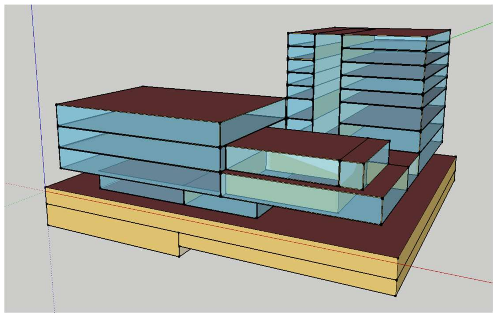
Figure 9.
Simulation flow chart of the constant water flow rate control method (CASE 1).

Figure 10.
Simulation flow chart of the variable water flow rate control method (CASE 2).

Figure 11.
Room temperature (CASE 1).

Figure 12.
Room temperature (CASE 2).

Figure 13.
Geothermal water temperature (CASE 1).
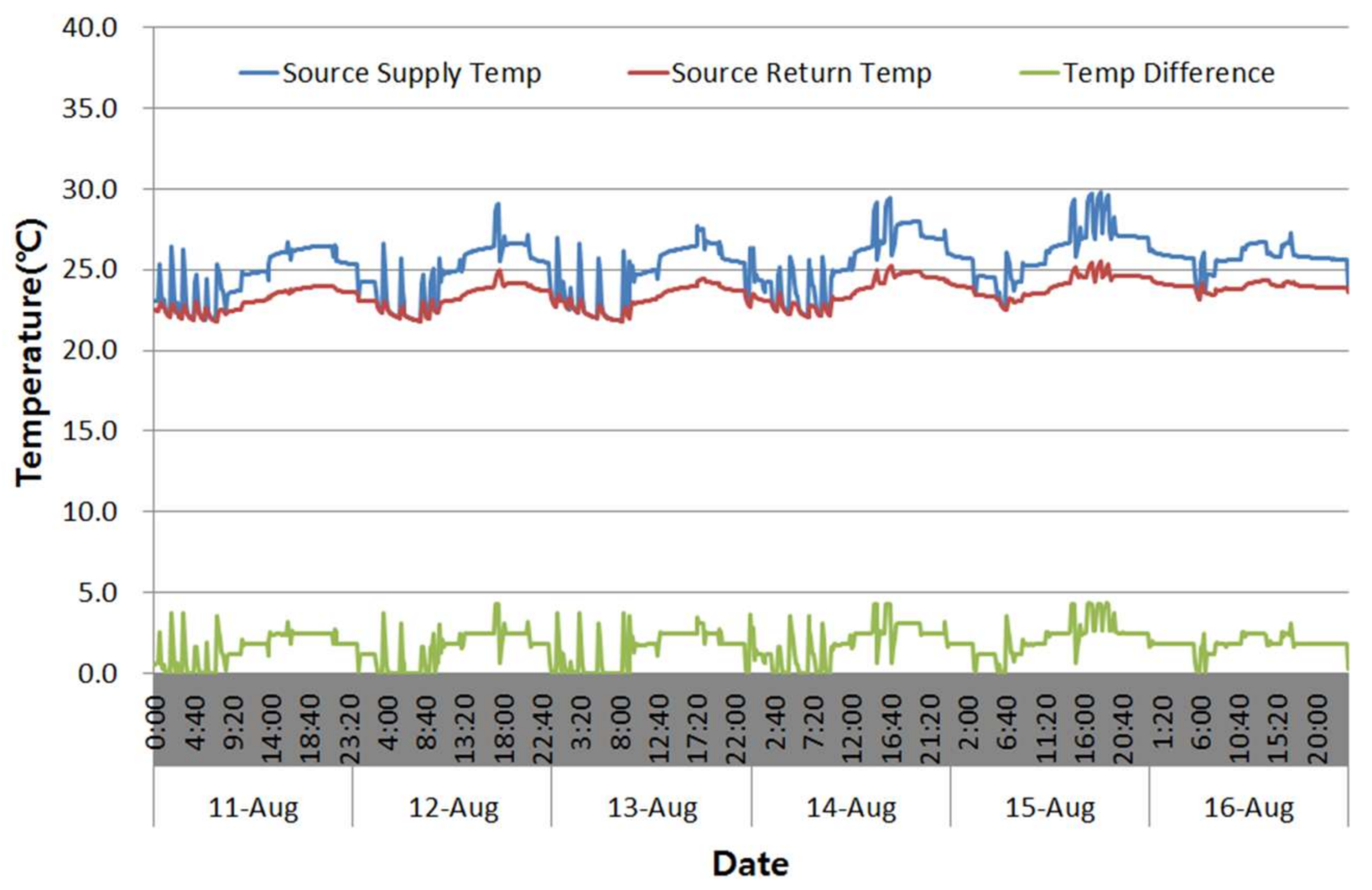
Figure 14.
Geothermal water temperature (CASE 2).

Figure 15.
Water flow rate.
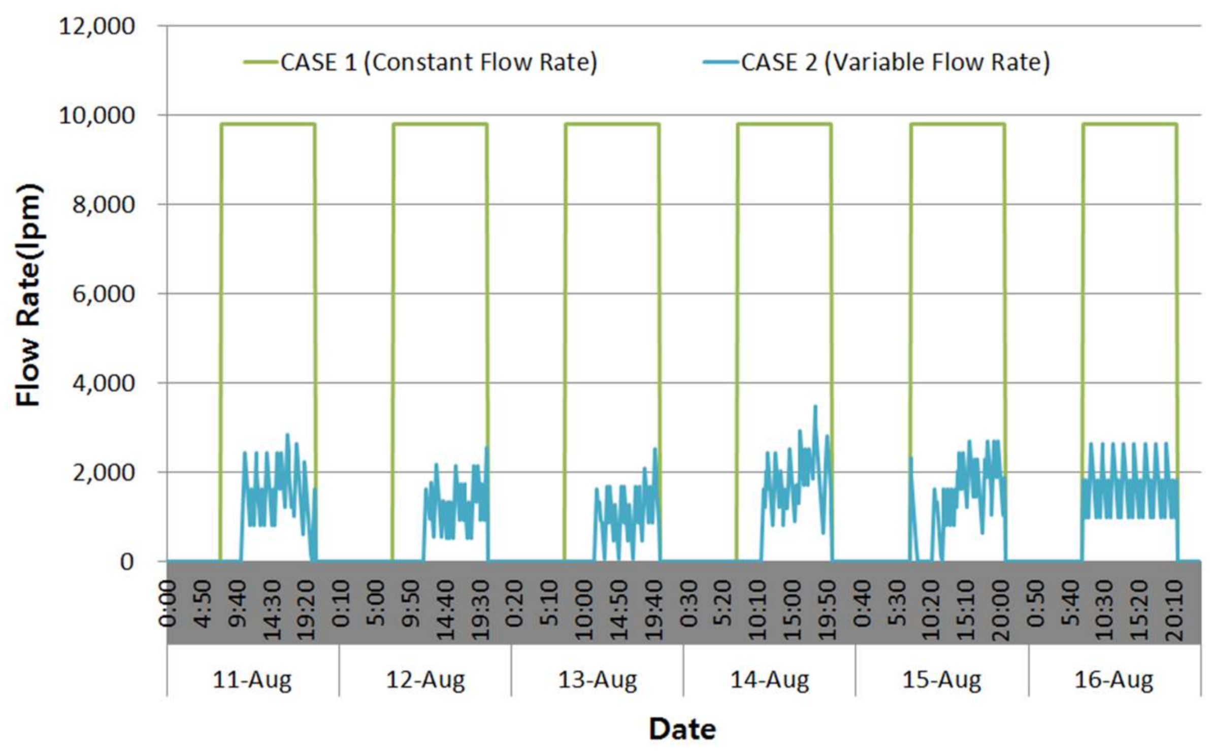
Figure 16.
Heat pump and circulation pump power consumption.


Table 1.
Building information.
| Classification | Contents |
|---|---|
| Location | Daegu, Korea |
| Building purpose | Mixed-use building (cultural and meeting facilities, business facilities, sales facilities) |
| Structure | Reinforced concrete |
| Building stories | The second basement/the ninth floor |
| Total floor area | 49,667 m2 |
Table 2.
Geothermal heat pump system information.
| Classification | GH-1 | |
|---|---|---|
| Quantity | 7 | |
| Capacity (USRT) | Cooling | Heating |
| 48.3 | 44.4 | |
| Entering source temperature (°C) | 25 | 5 |
| Supplied temperature (°C) | 12 | 40 |
| Flow Rate (LPM) | 600 | 600 |
Table 3.
Circulation pump information.
| Classification | GP-1 |
|---|---|
| Quantity | 8 |
| Power (kW) | 7.5 |
| Head (M) | 35 |
| Flow Rate (LPM) | 700 |
Table 4.
Indoor condition and Indoor load.
| Room | Summer | Winter | ||
|---|---|---|---|---|
| Temperature (°C) | Humidity (%) | Temperature (°C) | Humidity (%) | |
| Exhibition | 24 | 50 ± 5 | 20 | 40 ± 5 |
| Office | 24 | 50 ± 5 | 22 | 40 ± 5 |
| Library | 24 | 40 ± 5 | 20 | 40 ± 5 |
| Meeting room | 24 | 50 ± 5 | 20 | 40 ± 5 |
| Indoor load | ||||
| Person load | Seated, Light work, 150 W | |||
| Lighting load | 13 W/m2 | |||
| Device load | 16 W/m2 | |||
Table 5.
Summary of CASE.
| CASE | Control Method |
|---|---|
| CASE 1 | Existing Constant Water Flow Rate Control Method |
| CASE 2 | Proposed Variable Water Flow Rate Control Method |
Table 6.
Summary of CASE.
| CASE | Control Method |
| CASE 1 | Existing Flow Rate Control Method by Constant Flow Rate |
| CASE 2 | Proposed Flow Rate Control Method by Variable Flow Rate |
Table 7.
Heat pump and circulation pump power consumption (kW).
| CASE | Heat Pump | Circulation Pump | Total |
|---|---|---|---|
| CASE 1 | 134,336 | 48,600 | 182,936 |
| CASE 2 | 112,528 | 13,391 | 125,919 |
© 2018 by the authors. Licensee MDPI, Basel, Switzerland. This article is an open access article distributed under the terms and conditions of the Creative Commons Attribution (CC BY) license (http://creativecommons.org/licenses/by/4.0/).
Share and Cite
MDPI and ACS Style
Shin, J.-H.; Cho, Y.-H. Development of a Variable Water Flow Rate Control Method for the Circulation Pump in a Geothermal Heat Pump System. Energies 2018, 11, 718. https://doi.org/10.3390/en11040718
AMA Style
Shin J-H, Cho Y-H. Development of a Variable Water Flow Rate Control Method for the Circulation Pump in a Geothermal Heat Pump System. Energies. 2018; 11(4):718. https://doi.org/10.3390/en11040718
Chicago/Turabian StyleShin, Ji-Hyun, and Young-Hum Cho. 2018. "Development of a Variable Water Flow Rate Control Method for the Circulation Pump in a Geothermal Heat Pump System" Energies 11, no. 4: 718. https://doi.org/10.3390/en11040718
Note that from the first issue of 2016, this journal uses article numbers instead of page numbers. See further details here.