Analysis and Application of the Sliding Mode Control Approach in the Variable-Wind Speed Conversion System for the Utility of Grid Connection


1
Laboratory of Computer Science for Industrial Systems (LISI), 676 INSAT Urban Center North BP, CEDEX, Tunis 1080, Tunisa
2
Department of Electrical Engineering, High National School of Engineering of Tunis (ENSIT), University of Tunis, 5 Av Taha Hussein Montfleury, Tunis 1008, Tunisia
*
Author to whom correspondence should be addressed.
Energies 2018, 11(4), 720; https://doi.org/10.3390/en11040720
Submission received: 28 January 2018
/
Revised: 5 March 2018
/
Accepted: 14 March 2018
/
Published: 22 March 2018
(This article belongs to the Section F: Electrical Engineering)
Abstract
:The greatest requirement for Tunisian grid connections is low voltage ride through (LVRT). In fact, the network voltage generally results in a discrepancy between the generated active power and that which is delivered. This study was carried out to enhance the quality of the power injected into the grid by means of LVRT capability in Tunisian wind turbines using a permanent magnet synchronous generator (PMSG) controlled by the sliding mode control (SMC) approach based on direct power control (DPC) using space vector modulation (SVM). This approach was applied in order to control the active and reactive powers produced by the wind energy conversion system (WECS) and injected into the grid. Results obtained in MATLAB/Simulink simulations showed the efficiency of the introduced control strategy. An implementation in real time, using a dSpace1104 control board, was presented to illustrate the feasibility of the proposed control scheme and its effectiveness under fault conditions.
1. Introduction
Renewable energy (RE) is the preferred energy technology, and wind energy conversion systems (WECSs) are one of the most important sources. In recent years, WECSs based on permanent magnet synchronous generators (PMSGs) have become more popular in the wind energy community. Thus, PMSGs were used to improve the efficiency of the system and the WECS power factor [1]. In fact, PMSGs have been utilized to eliminate the need for a gearbox, which has further reduced maintenance costs [2]. Most studies carried out in the domain of WECSs have focused on the development of control strategies based on modern nonlinear control techniques to improve control capabilities for the purpose of supplying and regulating active and reactive powers. Therefore, diverse control approaches, such as fuzzy logic control [3], adaptive control [4], and robust control [5], have been applied to PMSG-based WECSs. A promising proposed control method for achieving high performance, durability, and stability is the sliding mode control (SMC) approach [6]. In this paper, we introduce a SMC approach combined with direct power control (DPC) using space vector modulation (SVM) (altogether, SMC-DPC-SVM) to regulate the active and reactive powers produced by the WECS and injected into the grid under constant DC link voltage (Vdc) [7]. The machine side converter (MSC) and grid side converter (GSC) are generally controlled by the SMC approach using SVM. In this work, the SMC-SVM approach was applied as the modulation strategy in the WECS, where it generated less harmonic distortion [8]. With the significant increase in wind capacity installed in transportation systems, a simultaneous outage of a large proportion of the generating capacity can affect the grid stability. Therefore, a wind turbine (WT) is required to stay operational in the event of grid disturbances so that it can continue to support the grid with reactive power during brownouts—hence the significance of low voltage ride through (LVRT), which is one of the most common and crucial grid connection requirements [9]. LVRT also facilitates fast restoration of active and reactive powers to pre-fault values after the system voltage returns to ordinary operation levels.
Various protection devices, such as crowbar circuits [10], energy storage systems [11], stator switches [12], and auxiliary parallel grid-side rectifiers [13], have already been used during grid faults. In this paper, the LVRT scheme provided by the wind grid codes was overhauled. We also examined the interconnection of WTs to the local grid in case of a fault occurring in the line grid and fault conditions and verified the robust of control. In our proposed PMSG-based WT configuration, various elements, such as the MSC and GSC controls based on the sliding mode control approach, current energies compensation, and LVRT, can be integrated in the same system.
In this context, many research studies have been performed. For instance, the authors in [14] presented a nonlinear control technique using the SMC strategy in order to alter the dynamics of a wind turbine system connected to the grid under severe faults of grid voltage. They discussed the transient behavior and identified the LVRT performance limit. Despite its importance, however, this work was not experimentally validated. In [15], researchers presented a LVRT control strategy designed by using SMC, based on the analysis of Doubly-fed electric machine (DFIG) dynamic mathematical models. Then, vector control and SMC were compared in an experiment simulating grid voltage depth dropping, which showed that the SMC strategy is more effective than the vector control strategy and is more beneficial for quick system recovery after grid faults. In [16], a LVRT scheme for a PMSG wind power system at a grid voltage sag was introduced. The DC link voltage was controlled by applying a feedback linearization theory. This control algorithm was validated by simulation and experimental results. In addition, a self-tuning resonant control (RC) system for LVRT control of the grid interface was employed with the presence of symmetrical or asymmetrical faults [17]. The present paper performs an analytical study of voltage dips to identify critical operating points for LVRT assessment with the SMC-DPC-SVM approach. This nonlinear control proved its efficiency in terms of the robustness and resolution of the LVRT scheme. The capability of LVRT in grid code requirements was investigated using a precise dynamic model. This application was not mentioned in the state-of-the-art review. Furthermore, the LVRT analysis was validated through experimental results in a test bench using a real-time system controller based on a dSpace 1104 controller board. Section 2 of this manuscript describes the PMSG WT configuration. Section 3 presents the SMC-SVM control of the MSC and GSC. In Section 4, we propose a LVRT control scheme for grid faults. Section 5 depicts a case study using MATLAB/Simulink software, the results of which show the efficiency of the developed control strategy and topology. Finally, Section 6 illustrates our experimental results and concludes our analysis.
2. System Description
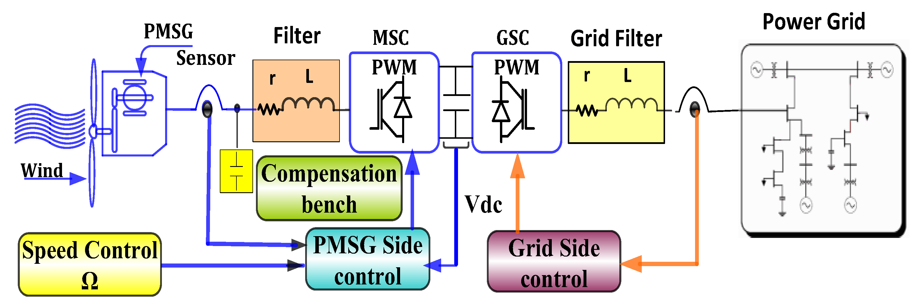
In this manuscript, we analyze the structure of a PMSG WT system composed of a variable WT based on a PMSG connected to the grid through a back-to-back converter shown in Figure 1. The first converter, the GSC, was controlled by the sliding mode control approach using SVM to control the instantaneous active and reactive powers. In contrast, the second converter, the MSC, was placed between the DC link capacitor and the grid in order to regulate the DC link voltage as well as the active and reactive powers flows.
2.1. Modeling of Wind Generation System
The kinetic energy of wind is given by:
The wind power is determined by:
The total kinetic power of the wind is: .
The mechanical power, which is converted by a WT, , is dependent on the power coefficient .
The power extracted from the wind turbine can be written as:
The mechanical torque of the turbine can be calculated from the mechanical power extracted from the WT [18]. Subsequently, the power coefficient is shown by Equation (3) and establishes a set of characteristics, given the available power and depending on the speed of the generator for various wind speed. The WT model is developed by Equation (3).
2.2. Permanent Magnet Synchronous Generator Model
The electric model of the PMSG in (d, q) reference frame can be written in the following form [19,20]:
The electromagnetic torque expression is:
2.3. The Equivalent Circuit and Model of the Converter Connected to the Grid
The GSC provides a constant DC bus voltage from the output of the MSC and abolishes the harmonic distortion of the grid currents. It is also characterized by its ability to recover energy and its wide field of view in the DC power supply, with reactive power compensation [21].
Using a simplified model of the GSC, we can determine the active and reactive powers injected into the grid.
The instantaneous active and reactive powers injected into the grid can be written as:
A non-perturbed grid line voltage is obtained:
The line voltage law of the grid is:
The instantaneous current variation is:
The active and reactive power derivatives are given by:
3. Proposed Sliding Mode Control Approach
3.1. The Principle of the Sliding Mode Control Approach
The SMC approach with DPC was a combined space vector modulation (SVM) employed to operate with constant switching frequency (CSF), which is the purpose of controlling the Vdc and directly regulating the instantaneous active and reactive powers of the PMSG WT voltage source converter [22,23]. The proposed SMC-DPC-SVM approach for the connected grid and PMSG WT will be described in the following section. In our experiments, the reference voltage for the MSC output was obtained in the stationary reference frame (Vα, Vβ) and transferred to the SVM module to generate the required switching voltage vectors and their respective time durations [24].
The Figure 2 shows the SMC-DPC-SVM structure of the voltage converter. The sliding mode control consists of strengthening the system’s trajectory to follow the reference quantities. The SMC_DPC provides the reference voltages (Vα, Vβ) to the SVM modulator to generate the states of the converter switches [25].
3.2. Sliding Surface
Tracking or sliding along the predetermined active and reactive power trajectories are the principal control objectives for the converters [26]. The expression of the sliding surface is as follows:
With the intention of maintaining the enhanced transient response and minimizing the steady-state error, the switching surfaces can be in the integral forms [27]; alternatively, they can also be designed via back-stepping and nonlinear damping techniques:
where and are the respective errors between Pg and Qg; (KP and KQ) > 0.
The manifolds SP = 0 and SQ = 0 represent the precise tracking of the converter’s Pg and Qg powers. When the system states reach the sliding manifold and slide along the surface, we have:
3.3. SMC Law
In this paper, an SMC scheme is proposed to generate the reference voltage of the converter output as the input to the Space Vector Pulse Width Modulation (SVPWM) module [28].
Substituting (14) into (17) leads to:
Let us consider the following quadratic Lyapunov function given by Equation (20).
The time derivative of the quadratic Lyapunov function is then given by:
The time variation of this function must be strictly negative with S ≠ 0, which is the precondition for the trajectory to draw toward the sliding surface. Therefore, the switch control law must be correctly chosen for this condition to be verified. The proposed SMC law is as follows:
In fact: .
Using Equation (20), we can extract the SMC control algorithm shown in Figure 3.
3.4. Proof of the Stability
For stability against sliding surfaces, it is sufficient to have dW/dt <0. By setting appropriate switch functions, stability can be achieved provided the following condition is satisfied, if and , then:
The time derivative of Lyapunov function dw/dt is then definitely <0 so the control system will be asymptotic steady.
4. Low Voltage Ride Through
To ensure the proper operation of the electrical grid, technical requirements were applied to each unit based on the renewable energy sources connected to the grid by low voltage inverters [28].
4.1. The Voltage Quality
In the case of a load fed through a line by a constant voltage source, the voltage drop in the line is given by: . The line voltage drop can be approximated by the following equation:
The expression (23) gives the line voltage drop that occurs deep in the grid, close to the bus connection of the wind turbine, because the active power generated by the wind turbine will be decreased.
4.2. Hold the Frequency and Voltage
Any renewable energy production unit must remain connected to the network in the frequency ranges [47.5, 52]. The connection of the production unit to the low voltage network must not result in an exceedance of the voltage limits defined in the specifications related to the electrical energy supply throughout the Republic—±10% of the rated voltage at low voltage [29]. In abnormal operating conditions, the electricity production units from renewable energies must remain connected to the network in the case of voltage drops of at least one of the three phases up to a value of 0.3 p.u. (30% of nominal voltage) for a minimum period of 200 ms. For voltage values between 30% and 90% of the nominal value, linear interpolation was applied. During a voltage drop (one of the three phases <90%), the absolute value of the current must not exceed the value of the current before the voltage drop.
The wind generator required the LVRT execution when the voltage in the grid was reduced due to a fault or large load change. LVRT behavior was defined in the Tunisian grid codes issued by the grid operators in order to maintain system stability and reduce the risk of voltage collapse. The production of electricity from RE installations must be able to remain in operation during a voltage dip. For asymmetric defects, the curve applies to the low voltage of the three phases. After the disturbance, renewable energy installations must contribute to making the network function under normal operating conditions (voltage and frequency). In addition, the active power should be restored within a maximum time that does not exceed one second after the voltage returns to its normal operating range. During the voltage reconstruction, the reactive power is less than the reactive power obtained before the fault occurrence [30].
4.3. Rapid Voltage Variation
Rapid voltage variations caused by the connection or disconnection of auto-producers should not be superior to 3% of the nominal voltage at the connection bus. The fast voltage variation can be evaluated by applying the following equation:
4.4. The Hold of Reactive Current
To maintain the connection into the grid in voltage-dips situations, renewable energy generators, such as conventional power plants, must inject additional reactive power into the grid [5]. Similarly, in order to reduce the voltage to acceptable values, renewable energy generators have to generate more the reactive power during surges. A typical feature of maintaining the reactive current is shown in Figure 3. In order to stabilize the voltage across the electrical network, in the case of symmetrical and asymmetrical faults, injection or absorption of an additional reactive current by a production unit must satisfy the following conditions:
- The time period for the injection or absorption of the reactive current must be within the minimum fault clearing time; this period is equal to 60 ms.
- The difference between the voltage obtained before disturbance and that provided after it is as follows: .
- Or Un: is a permissible rated voltage.
- The difference between the current obtained before the disturbance and that provided after it is: .
K is defined as a proportionality factor between the current and the voltage. It is adjustable by the dispatching center and it varies between 0 and 10 .
4.5. Fault Mode
The implementation of the control strategy on this WT technology is easy due to the fact the GSC is the only element connected to the grid. Furthermore, it could be considered that, in normal operation, the power transfer from the generator to the grid is unidirectional. For effective operation, it is enough to reduce the transfer of active power from the DC link to the grid. In the event of a fault in the grid, the WECS must provide a reactive power proportional to the magnitude of the voltage drop. In addition, the magnitude of the grid current must not exceed the rated value in order to protect the semi-conductor constituting the grid side converter [27]. The relationship between grid voltage, the reactive power injected into the grid, and the active power reference is given by (24):
That means:
- if Pg_ref = Pref → no loss at the line;
- if Pgref < Pref → a fault that must be compensated for the voltage.
Figure 4 depicts the Pg_ref and Qg_ref under LVRT. Therefore, we have to offset the loss that is caused by the voltage drop with the reactive power. Obviously, it is the role of the WECS to provide more reactive power to the Tunisian grid.
5. Simulation and Experimental Results
With the intention of evaluating the dynamic responses of the proposed system, extensive simulations were performed using MATLAB/Simulink software (Tunis, Tunisia) to examine the control algorithm using the SMC-DPC-SVM approach to the PMSG WT connected to the grid. Furthermore, the simulations were validated by experimental results obtained by implementing the wind emulator prototype built to emulate the behavior of the WT. The speed variation of the WT was generated by a servomotor, which provided a true wind profile produced by the Active servo software connected simultaneously to a second computer. The proposed control strategy algorithm was implemented by employing a dSpace1104 controller board. The parameters of the test bench used were listed in the following Table 1, Table 2, Table 3 and Table 4, respectively. Figure 5 shows the laboratory test bench.
The experimental test was organized into three cases as follows:
5.1. Case I: Simulation and Experimental Results of the Wind Turbine under SMC-DPC-SVM Control of the Machine Side Converter
In this first case, we tested the transient responses of the MSC to sliding mode control under active power variation. The tests for examining the control algorithm of the sliding mode were carried out with a closed control loop and under unit power factor (reactive power reference was equal to zero), producing a rapid response to the active and reactive powers of the SMC-DPC-SVM strategy. The proposed SMC-DPC-SVM algorithm obtained clearly improved performances with smoothed active/reactive powers.
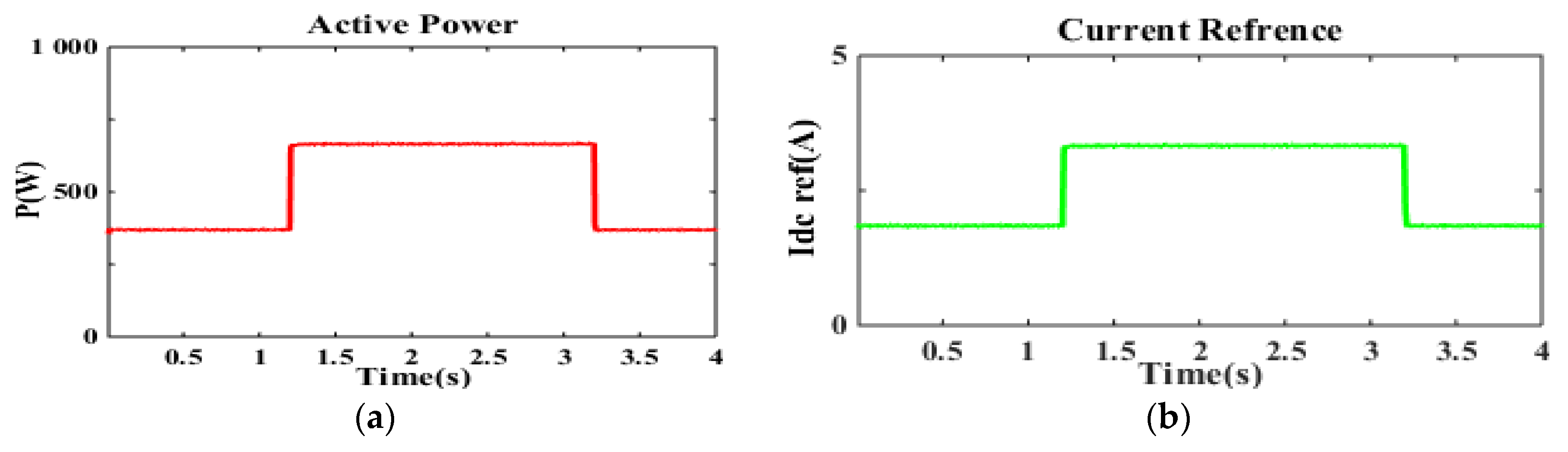
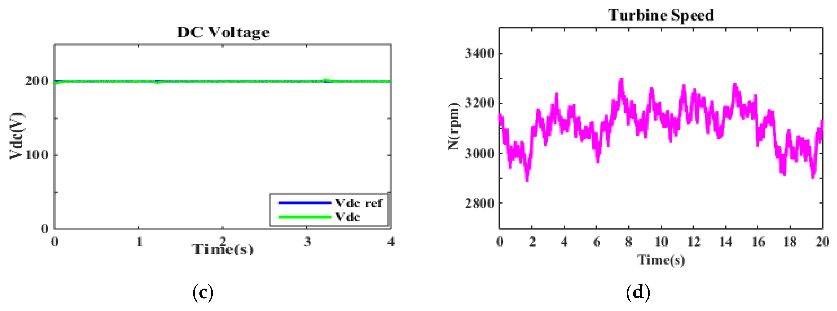
In fact, we tested the transient responses of the MSC rectifier with sliding mode control under active power variation. The DC link voltage was regulated at 200 V. The Vdc was constant and equal to its reference value (see Figure 6c). After that, we tested the proposed algorithm with a variable resistor load level to prove the efficiency of the DC link regulator control. The active power increased from 370 W to 670 W at 1.3 s. Then, it decreased to 370 W at 3.2 s, as shown in Figure 6a. In addition, the DC current, regulated with the Proportional Integral (PI) controller, remained constant and did not exceed 1.9 A, (Figure 6c). With the increase of power, the current increases and remains fixed at 3.35 A. Figure 6b shows that, despite the turbine speed change, the used controller was set in such a way that maintained the DC bus voltage constant at 200 V.
We noticed that the active power was constant; it did not change despite the wind turbulence due to the efficiency of the PI regulator, and the same applies to the reactive power and current.
5.2. Case II: Simulation and Experimental Results Provided by the Grid Side Converter Using the SMC-DPC-SVM Approach
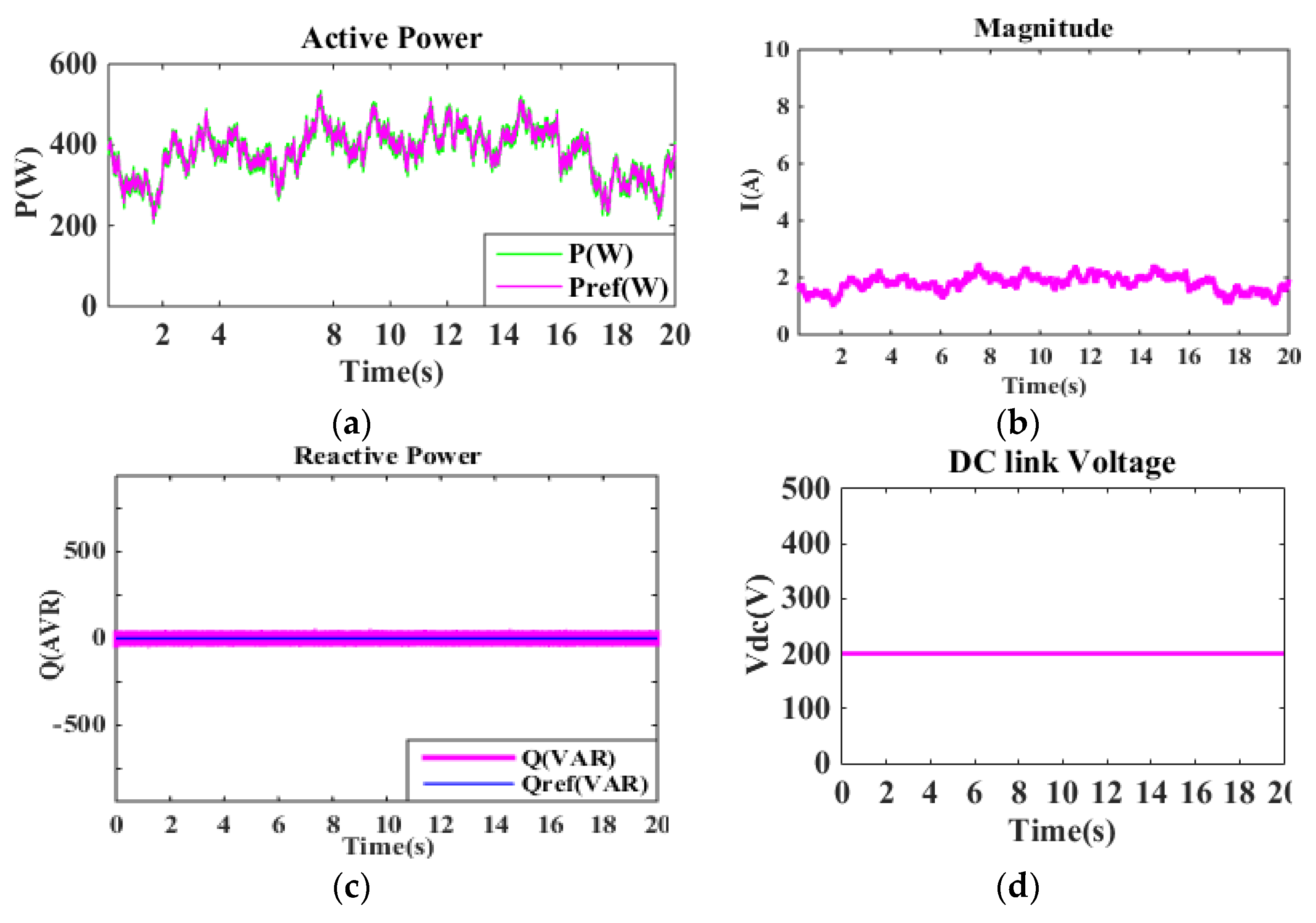
The stochastic wind input is demonstrated in Figure 7. The present variable wind profile, varying around its nominal value (12 m/s), is composed of 6 m/s and 16 m/s.
The active power injected into the grid is presented in Figure 8a and Figure 9a. As we can see, the power converged to its desired reference with fast dynamics. The generated active power was transferred to the grid. In addition, the current amplitude variation had the same shape as the active power reference, (Figure 8b and Figure 9b). These figures reveal that the output reactive power injected into the grid Qg remained constant (0 VAR), which maintained the power factor at a value almost equal to one despite the variation of the active power during the experimental test. Moreover, Figure 8d and Figure 9d evidence that the proposed approach maintained the Vdc constant under wind speed variations, where the DC link voltage response was obtained using the proposed SMC-DPC-SVM approach.
Our control is a hybrid control because we used the SMC-DPC-SVM approach. This approach is robust and efficient. It can be implemented with the LVRT technique. Therefore, this is a strong strategy compared to the other methods that we discussed in the Introduction.
5.3. Case III: Study of the LVRT in the Tunisian Grid Code
The obtained results show the execution of the LVRT required by the Tunisian grid code, which was simulated by MATLAB/Simulink software and checked by experimental results.
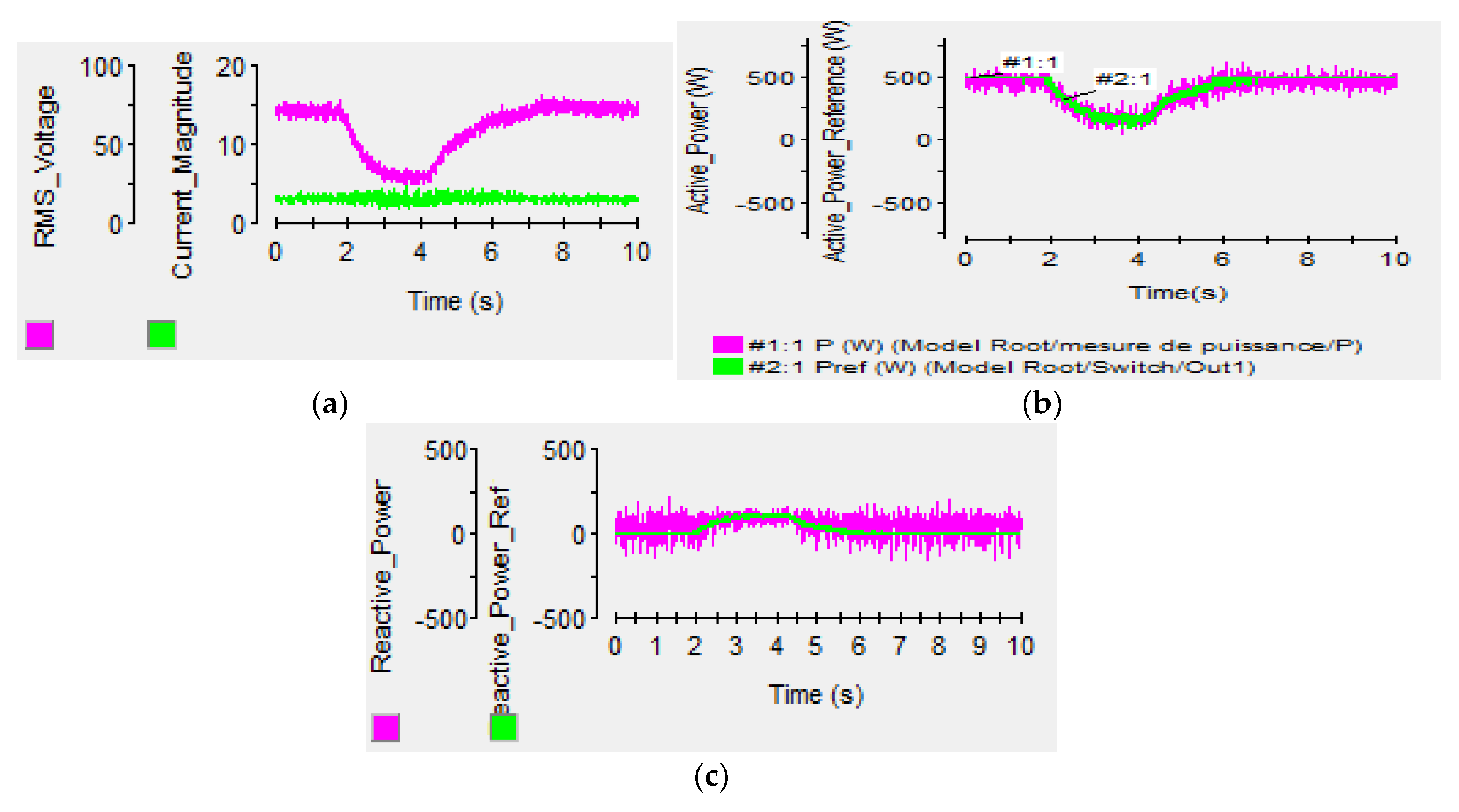
The voltage drop amplitude resulted from −10% of the rated voltage for a few seconds and decreased from 72 V to 25 V for 0.1 s. After that, the voltage increased until it reached the initial value in order to obtain a constant current amplitude, as shown in Figure 10a. Moreover, the power had the same profile as the voltage (−10% of the active power) in a way that made it decrease from 500 W to 50 W for 0.1 s, as is illustrated in Figure 10b. Then, the active power increased until it reached the power initial value. During this default, the profile of the reactive power, whose value increased from 0 VAR to 200 VAR, changed (Figure 10c).
Figure 11 shows a selection of waveforms extracted from the experimental test of the LVRT grid code capability curve used in our laboratory. Obviously, when the voltage decreased from 72 V to 25 V, the line current amplitude injected into the grid remained constant and the active power decreased from 500 W to 50 W. In addition, to avoid this voltage drop and to correct and eliminate the maximum default, the reactive power should be proportional to the magnitude of the voltage drop, which increased from 0 VAR to 200 VAR.
Our LVRT technique has many advantages. It is a reliable method and easy to implement. It has a simple compensation device, which is not expensive to apply in a test bed. This technique is not used at the level of the network of the Tunisian Republic, because our country generally uses either a compensation battery or an energy management coil, which can unfortunately lead to blackouts.
6. Conclusions
In this paper, we proposed a SMC-DPC-SVM approach for a PMSG drive used in variable speed wind power generations connected to the grid in Tunisia. The verification of the control algorithm was validated by both simulations and experiments. During grid faults, a LVRT strategy proposed for the grid side converter provided reactive support to the power grid and maintained the energy balance of the system in a manner that complies with Tunisian grid codes. The developed system combined wind power integration control, reactive power compensation, and LVRT operations to improve the stability and quality of power injected into the grid. The implementation results in our laboratory validated the performance of the LVRT scheme.
We proved through simulations and experimental results that the LVRT technique was efficiently implemented in a hybrid system comprised of a sliding control mode using direct power control with space vector modulation, or “SCM-DPC-SVM”. It has a simple compensation device, which is not expensive and is easy to implement. This strategy was integrated into a real grid—the grid of the Tunisian Republic. In addition, the effectiveness of the proposed method was shown especially in efficiency of its robustness. In contrast, our established system in Tunisia uses either a compensation battery or energy management coil, which are prone to blackouts. We noticed that, during the occurrence of a fault in the network, the quality of the voltage signals was improved with LVRT and by applying the proposed SMC-DPC-SVM strategy. During grid faults, these signals were subject to remarkable declines. However, our strategy re-established voltage levels and prevented the network from failing in blackouts. It also proved its efficiency in reducing response times during the occurrences of such faults. The SMC-DPC-SVM strategy was also used to correct the default in approximately one second.
Acknowledgments
This work was partly supported by the Tunisian Ministry of Higher Education and Research under Laboratory of Computer for Industrial Systems, INSAT, University of Carthage, ‘LR11ES26’.
Author Contributions
This paper is the results of the work of all authors, Maha Zoghlami, Ameni Kadri and Faouzi Bacha designed the test bench. They also implemented the control strategies and performed experimental results. All authors contributed in bibliographical research, analysis and discussions of the results.
Conflicts of Interest
The authors declare no conflict of interest.
References
- Zoghlami, M.; Kharoui, R.; Fnaeich, N.; Bacha, F. Direct Power Control Strategy for Variable Speed Wind Energy Conversion System Based on PMSM Generator. In Proceedings of the International Symposium on Power Electronics, Electrical Drives, Automation and Motion (SPEEDAM 2016), Anacapri, Italy, 22–24 June 2016. [Google Scholar]
- Orlando, N.A.; Liserre, M.; Mastromauro, R.A.; Dell Aquila, A. A survery of control issues in PMSG-based small wind-turbine systems. IEEE Trans. Ind. Inform. 2013, 9, 1211–1221. [Google Scholar] [CrossRef]
- Galadi, V.; Piccolo, A.; Siano, A. Designing an adaptive fuzzy controller for maximum wind energy extraction. IEEE Trans. Energy Convers. 2008, 23, 559–569. [Google Scholar] [CrossRef]
- Giraldo, E.; Garces, A. An adptive control strategy for a wind energy conversion system based on a PWM-CSC and PMSG. IEEE Trans. Power Syst. 2014, 29, 1446–1453. [Google Scholar] [CrossRef]
- Howlader, A.; Urasaki, N.; Yona, A.; Senjyu, T.; Saber, A. Design and Implement a Digital H∞ Robust Controller for a MW-Class PMSG-Based Grid-Interactive Wind Energy Conversion System. Energies 2013, 6, 2084–2109. [Google Scholar] [CrossRef]
- Vu, N.T.; Yu, D.Y.; Choi, H.H.; Jung, J.W. TS Fuzzy-Model-Based Sliding-Mode Control for Surface-Mounted Permanent-Magnet Synchronous Motors Considering Uncertainties. IEEE Trans. Ind. Electron. 2013, 60, 4281–4291. [Google Scholar] [CrossRef]
- Zoghlami, M.; Bacha, F. Implementation of Different Strategies of Direct Power Control. In Proceedings of the 6th International Renewable Energy Congress (IREC 2015), Sousse, Tunisia, 24–26 March 2015. [Google Scholar]
- Yassin, H.M.; Hanafy, H.H.; Hallouda, M.M. Enhancement low-voltage ride through capability of permanent magnet synchronous generator-based wind turbines using interval type-2 fuzzy control. IET Renew. Power Gener. 2016, 10, 339–348. [Google Scholar] [CrossRef]
- Conroy, J.F.; Watson, R. Low-voltage ride-through of a full converter wind turbine with permanent magnet generator. IET Renew. Power Gener. 2007, 1, 182–189. [Google Scholar] [CrossRef]
- Justo, J.J.; Bansal, R.C. Parallel R-L configuration crowbar with series R-L circuit protection for LVRT strategy of DFIG under transient-state. Electr. Power Syst. Res. 2018, 154, 299–310. [Google Scholar] [CrossRef]
- Saadat, N.; Choi, S.S.; Vilathgamuwa, D.M.A. Statistical evaluation of the capability of distributed renewable generator-energy-storage system in providing load low-voltage ride-through. IEEE Trans. Power 2015, 30, 1128–1136. [Google Scholar] [CrossRef]
- Shi, L.; Chen, N.; Lu, Q. Dynamic Characteristic Analysis of Doubly-fed Induction Generator Low Voltage Ride-through. Energy Procedia 2012, 16, 1526. [Google Scholar] [CrossRef]
- Wu, Z.; Dou, X.; Chu, J.; Hu, M. Operation and Control of a Direct-Driven PMSG-Based Wind Turbine System with an Auxiliary Parallel Grid-Side Converter. Energies 2013, 6, 3405–3421. [Google Scholar] [CrossRef]
- Saad, N.H.; Sattar, A.A.; Mansour, A.M. Low voltage ride through of doubly-fed induction generator connected to the grid using sliding mode control strategy. Renew. Energy 2015, 80, 583–594. [Google Scholar] [CrossRef]
- Zeng, B.; Zou, J.X.; Li, K.; Xin, X.S. A novel sliding mode control based low voltage ride through strategy for wind turbine. In Applied Mechanics and Materials; Trans Tech Publications: Zürich, Switzerland, 2014; Volume 548–549, pp. 890–894. [Google Scholar]
- Zhuo, G.; Hostettler, J.D.; Gu, P.; Wang, X. Robust Sliding Mode Control of Permanent Magnet Synchronous Generator Based Wind Energy Conversion Systems. Sustainability 2016, 8, 1265. [Google Scholar] [CrossRef]
- Alizadeh, O.; Yazdani, A. A Strategy for Real Power Control in a Direct-Drive PMSG-Based Wind Energy Conversion System. IEEE Trans. Power Deliv. 2013, 28, 1297–1305. [Google Scholar] [CrossRef]
- Yaramasu, V.; Wu, B.; Rivera, M.; Rodriguez, J. A new power conversion system for megawatt pmsg wind turbines using four-level converters and a simple control scheme based on two-step model predictive strategy—Part II: Simulation and experimental analysis. IEEE J. Emerg. Sel. Top. Power Electron. 2014, 2, 14–25. [Google Scholar] [CrossRef]
- Teninge, A.; Roye, D.; Bacha, S. Reactive Power Control for Variable Speed Wind Turbines to Low Voltage Ride through Grid Code Compliance. In Proceedings of the XIX International Conference on Electrical Machines (ICEM 2010), Rome, Italy, 6–8 September 2010. [Google Scholar]
- Zhang, X.; Wu, Z.; Hu, M.; Li, X.; Lv, G. Coordinated Control Strategies of VSC-HVDC-Based Wind Power Systems for Low Voltage Ride Through. Energies 2015, 8, 7224–7242. [Google Scholar] [CrossRef]
- Cárdenas, R.; Díaz, M.; Rojas, F.; Clare, J.; Wheeler, P. Resonant control system for low-voltage ride-through in wind energy conversion systems. IET Power Electron. 2016, 9, 1297–1305. [Google Scholar] [CrossRef]
- Magesh, M.; Sundareswaran, R. PMSG Based Wind Energy Conversion with Space Vector Modulation. Int. J. Energy Power Eng. 2015, 4, 146–152. [Google Scholar] [CrossRef]
- Teninge, A.; Jecu, C.; Roye, D.; bacha, S.; Duval, J.; Belhomme, R. Contrubution to frequency control through wind turbine inertial energy storage. IET Renew. Power Gener. 2009, 3, 358–370. [Google Scholar] [CrossRef]
- Merzoug, M.; Benall, H.; Louze, L. Sliding Mode Control (SMC) of Permanent Magnet Syncronous Generators (PMSG). Energy Procedia 2012, 18, 43–52. [Google Scholar] [CrossRef]
- Errami, Y.; Ouassaid, M.; Cherkaoui, M.; Maaroufi, M. Variable Structure Sliding Mode Control and Direct Torque Control of Wind Power Generation System Based on the PM Synchronous Genrator. J. Electr. Eng. 2015, 66, 121–131. [Google Scholar]
- Karoui, R.; Zoghlami, M.; Bacha, F. Impact of the STATCOM on the Terminal Voltage of a Wind Farm of Bizerte in Tunisia. In Proceedings of the 2016 7th International Renewable Energy Congress (IREC), Hammamet, Tunisia, 22–24 March 2016. [Google Scholar]
- Karoui, R.; Aouiti, A.; Zoghlami, M.; Bacha, F. Impact of static synchronous compensator on the stability of a wind farm: Case study of wind farm in Tunisia. Wind Eng. 2016, 40, 555–568. [Google Scholar] [CrossRef]
- Zhong, C.; Wei, L.; Yan, G. Low Voltage Ride-through Scheme of the PMSG Wind Power System Based on Coordinated Instantaneous Active Power Control. Energie 2017, 10, 995. [Google Scholar] [CrossRef]
- Abdelrahem, M.; Kennel, R. Fault-Ride through Strategy for Permanent-Magnet Synchronous Generators in Variable-Speed Wind Turbines. Energies 2016, 9, 1066. [Google Scholar] [CrossRef]
- Decree of December 2016 Relating to the Technical Requirements of Connection and Evacuation of the Energy Produced from Renewable Energy Installations on the Low Voltage Network. 2017. Available online: http://www.legislation.tn/fr/detailtexte/Arr%C3%AAt%C3%A9-num-2017-0394-du-09-02-2017-jort-2017-013__20170130X3944 (accessed on 26 January 2018).
Figure 1.
Structure of the permanent magnet synchronous generator (PMSG) wind turbine (WT) connected to the grid.
Figure 1.
Structure of the permanent magnet synchronous generator (PMSG) wind turbine (WT) connected to the grid.

Figure 2.
Block diagram of the direct power controlled by the sliding mode control (SMC) approach with direct power control (DPC) using space vector modulation (SVM): (a) grid side, (b) wind energy conversion system (WECS) side.
Figure 2.
Block diagram of the direct power controlled by the sliding mode control (SMC) approach with direct power control (DPC) using space vector modulation (SVM): (a) grid side, (b) wind energy conversion system (WECS) side.
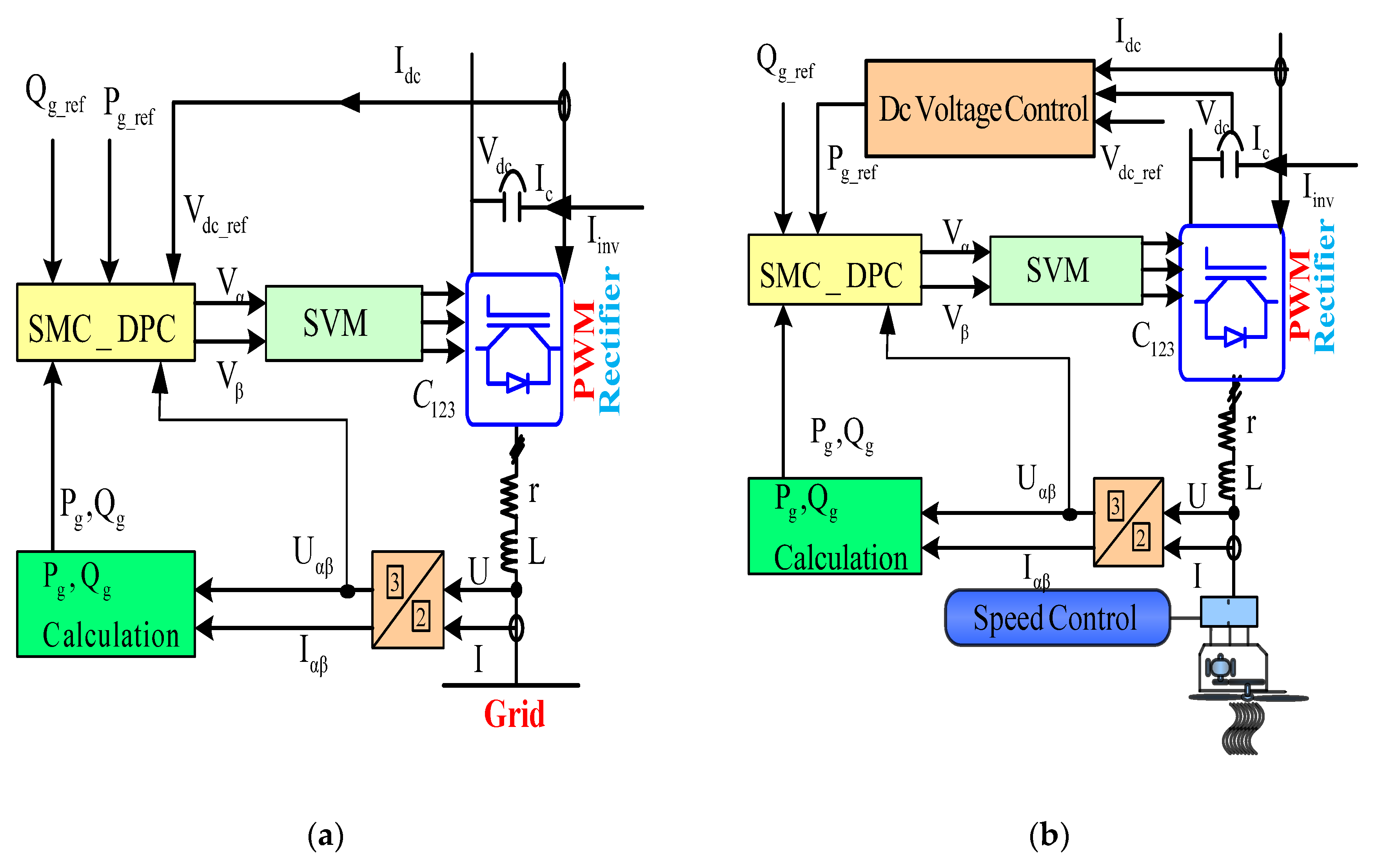
Figure 3.
Schematic of the SMC strategy for the MSC and GSC converters.
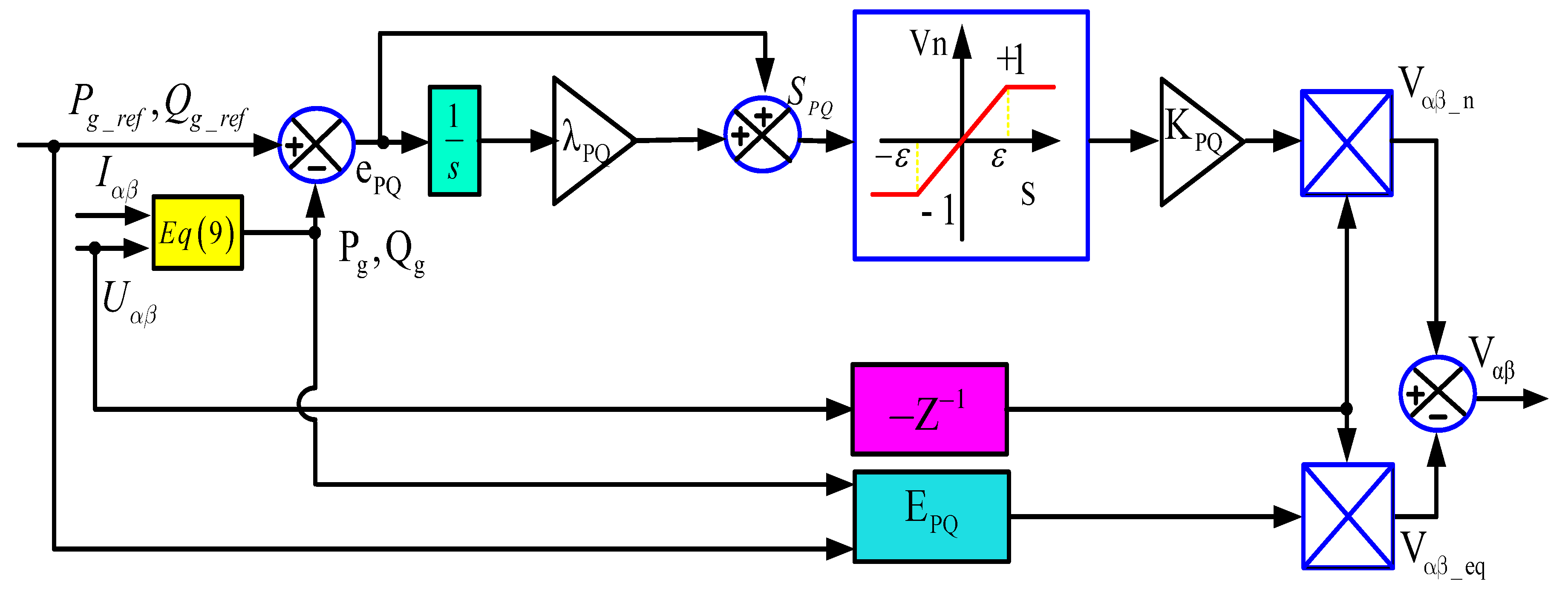
Figure 4.
Active and reactive power references under low voltage ride through (LVRT).
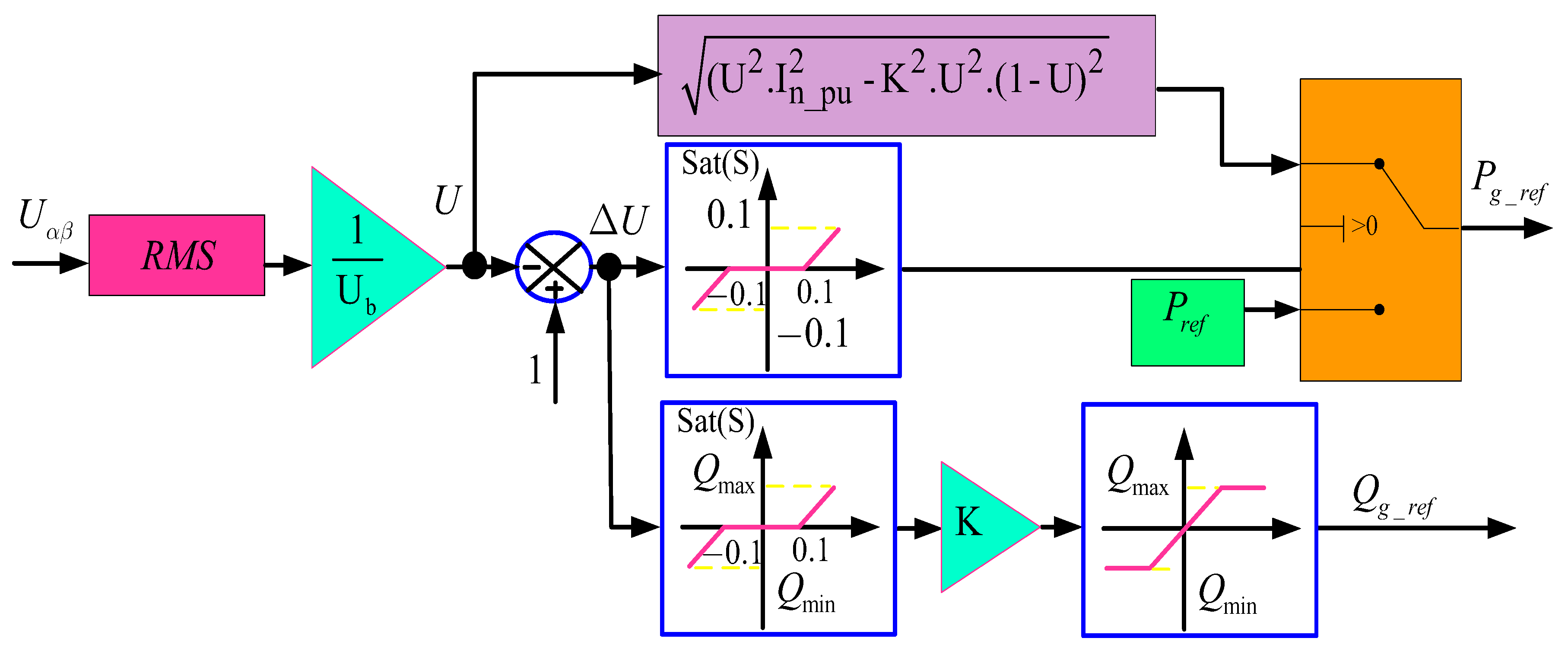
Figure 5.
Test bench photo.
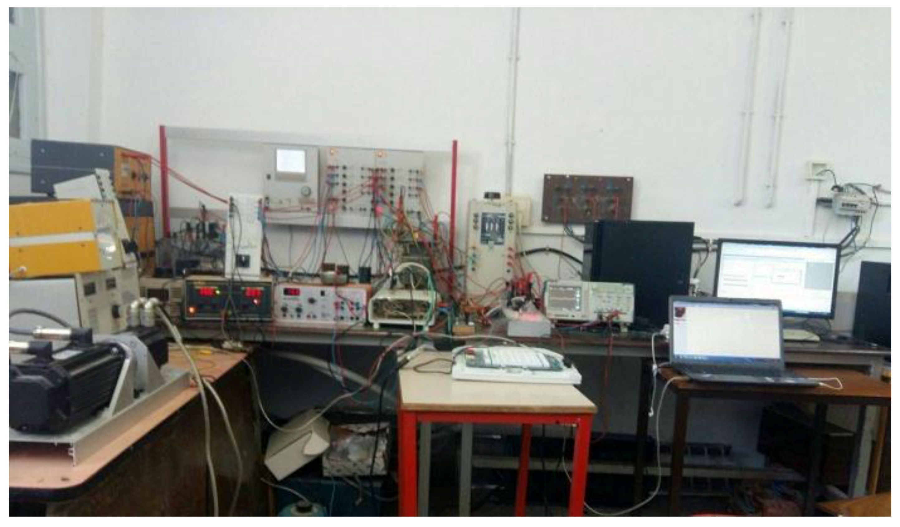
Figure 6.
Simulation results obtained by applying the wind turbine to SMC-DPC-SVM control of the machine side converter: (a) active power output Pg; (b) DC current reference Idc_ref; (c) DC bus voltage; (d) turbine speed.
Figure 6.
Simulation results obtained by applying the wind turbine to SMC-DPC-SVM control of the machine side converter: (a) active power output Pg; (b) DC current reference Idc_ref; (c) DC bus voltage; (d) turbine speed.


Figure 7.
Wind speed profile.
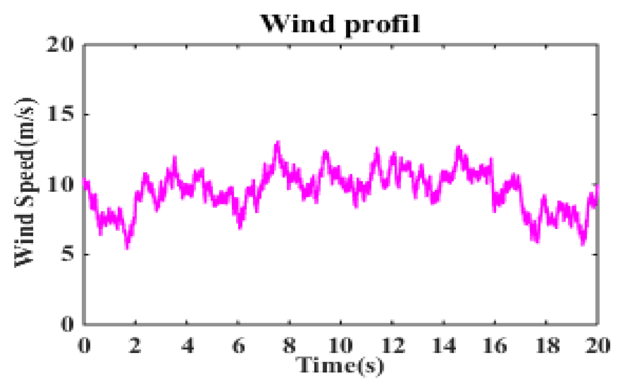
Figure 8.
Simulation results of the wind turbine with SMC-DPC-SVM control of the machine side converter: (a) active power output Pg; (b) DC current reference Idc_ref; (c) turbine speed; (d) DC-link voltage Vdc.
Figure 8.
Simulation results of the wind turbine with SMC-DPC-SVM control of the machine side converter: (a) active power output Pg; (b) DC current reference Idc_ref; (c) turbine speed; (d) DC-link voltage Vdc.

Figure 9.
Experimental results of the wind turbine with SMC-DPC-SVM control of the machine side converter: (a) active power output Pg; (b) current magnitude; (c) reactive power output Qg; (d) DC current reference Idc_ref.
Figure 9.
Experimental results of the wind turbine with SMC-DPC-SVM control of the machine side converter: (a) active power output Pg; (b) current magnitude; (c) reactive power output Qg; (d) DC current reference Idc_ref.
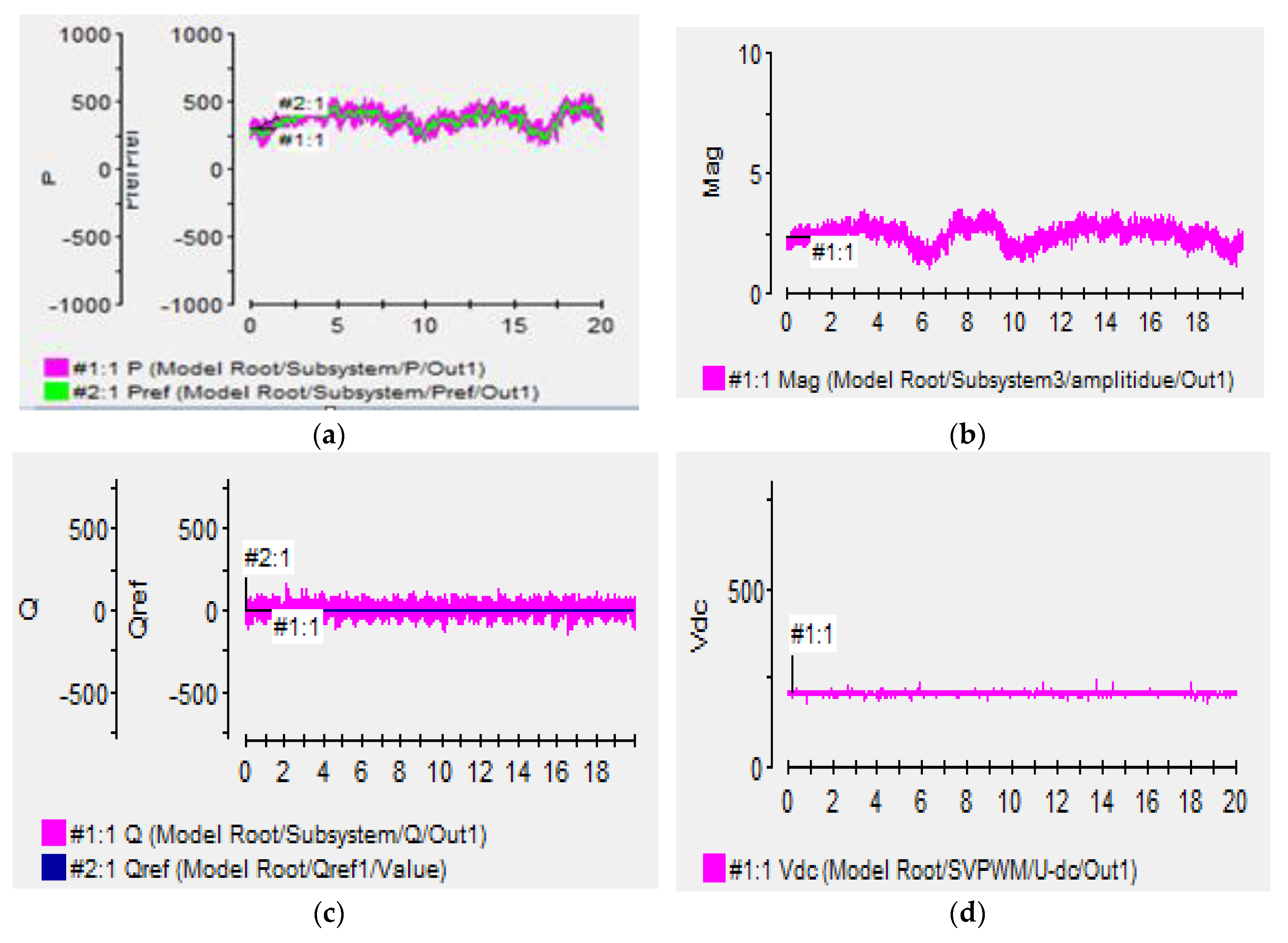
Figure 10.
Study of the LVRT in the Tunisian grid code simulated with MATLAB/Simulink: (a) Root mean square (RMS) voltage and current magnitude; (b) active power; and (c) reactive power.
Figure 10.
Study of the LVRT in the Tunisian grid code simulated with MATLAB/Simulink: (a) Root mean square (RMS) voltage and current magnitude; (b) active power; and (c) reactive power.
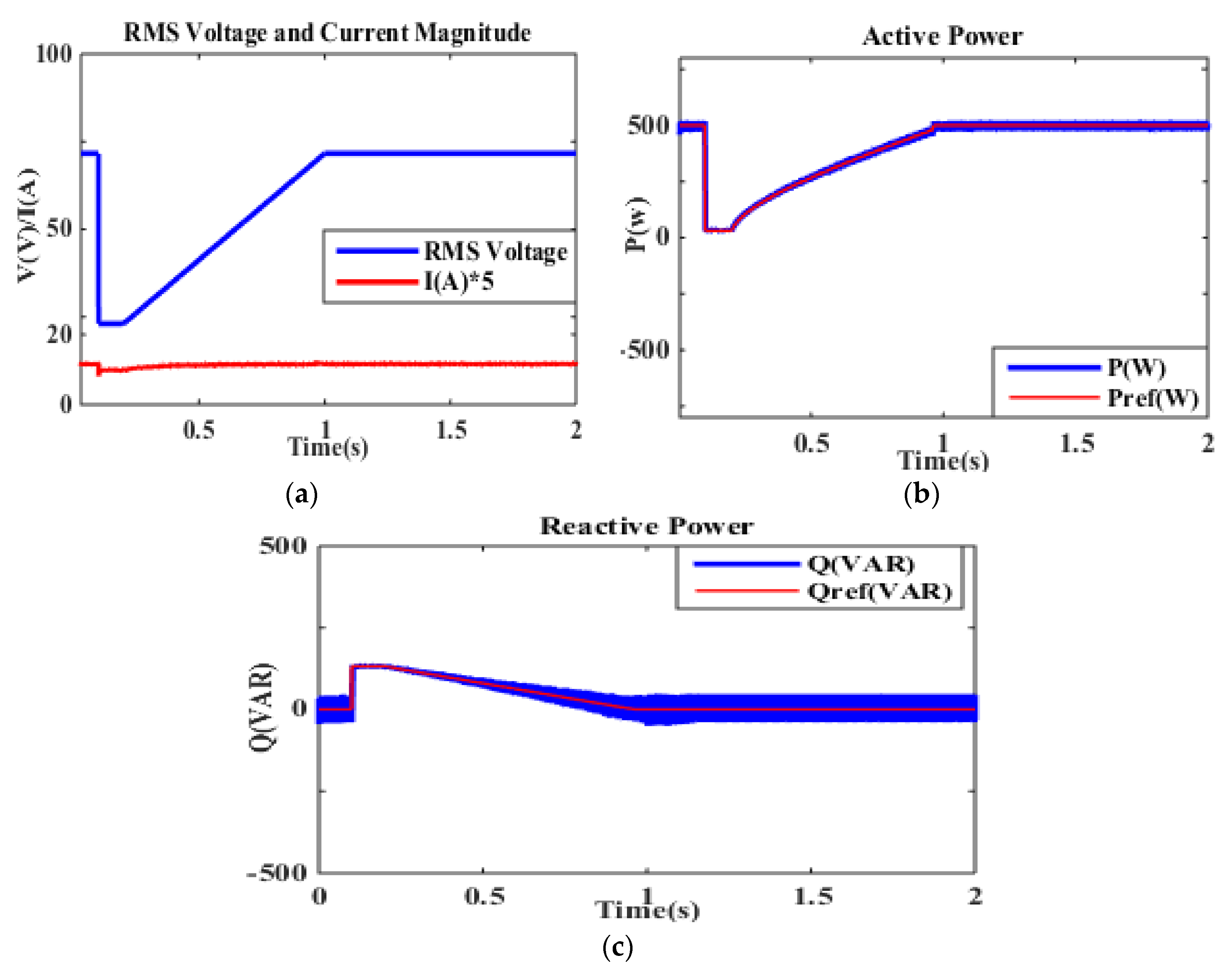
Figure 11.
Study of the LVRT in the Tunisian grid code simulation with dSpace1104: (a) RMS voltage and current magnitude; (b) active power; and (c) reactive power.
Figure 11.
Study of the LVRT in the Tunisian grid code simulation with dSpace1104: (a) RMS voltage and current magnitude; (b) active power; and (c) reactive power.


Table 1.
Wind turbine parameter.
| Characteristic | Value |
|---|---|
| Blade radius R | 1.02 m |
| J | 7.2 Kg·m |
| F | 0.0018 N·m/s |
| Vw | 12 m/s |
Table 2.
PMSG parameter.
| Characteristic | Value |
|---|---|
| Rated power | 1570 W |
| Ld = Lq | 3.9 mH |
| Rs | 0.5 Ω |
| p | 4 |
| F | 400 Hz |
Table 3.
Parameter of the grid.
| Characteristic | Value |
|---|---|
| Rated power | 500 W |
| U | 110 V |
| L, r | 12 mH, 0.6 Ω |
| Vdc | 200 V |
| F | 50 Hz |
Table 4.
Control parameters of the SMC regulator.
| Characteristic | Value |
|---|---|
| Positive gains Kp KI | 2500 |
© 2018 by the authors. Licensee MDPI, Basel, Switzerland. This article is an open access article distributed under the terms and conditions of the Creative Commons Attribution (CC BY) license (http://creativecommons.org/licenses/by/4.0/).
Share and Cite
MDPI and ACS Style
Zoghlami, M.; Kadri, A.; Bacha, F. Analysis and Application of the Sliding Mode Control Approach in the Variable-Wind Speed Conversion System for the Utility of Grid Connection. Energies 2018, 11, 720. https://doi.org/10.3390/en11040720
AMA Style
Zoghlami M, Kadri A, Bacha F. Analysis and Application of the Sliding Mode Control Approach in the Variable-Wind Speed Conversion System for the Utility of Grid Connection. Energies. 2018; 11(4):720. https://doi.org/10.3390/en11040720
Chicago/Turabian StyleZoghlami, Maha, Ameni Kadri, and Faouzi Bacha. 2018. "Analysis and Application of the Sliding Mode Control Approach in the Variable-Wind Speed Conversion System for the Utility of Grid Connection" Energies 11, no. 4: 720. https://doi.org/10.3390/en11040720
Note that from the first issue of 2016, this journal uses article numbers instead of page numbers. See further details here.