Design and Experiment Analysis of a Direct-Drive Wave Energy Converter with a Linear Generator

1
School of Electrical Engineering, Southeast University, Nanjing 210096, China
2
Department of Electrical Engineering, Jinling Institute of Technology, Nanjing 211169, China
*
Author to whom correspondence should be addressed.
Energies 2018, 11(4), 735; https://doi.org/10.3390/en11040735
Submission received: 10 February 2018
/
Revised: 16 March 2018
/
Accepted: 22 March 2018
/
Published: 23 March 2018
(This article belongs to the Special Issue Marine Energy)
Abstract
:Coastal waves are an abundant nonpolluting and renewable energy source. A wave energy converter (WEC) must be designed for efficient and steady operation in highly energetic ocean environments. A direct-drive wave energy conversion (D-DWEC) system with a tubular permanent magnet linear generator (TPMLG) on a wind and solar photovoltaic complementary energy generation platform is proposed to improve the conversion efficiency and reduce the complexity and device volume of WECs. The operating principle of D-DWECs is introduced, and detailed analyses of the proposed D-DWEC’s floater system, wave force characteristics, and conversion efficiency conducted using computational fluid dynamics are presented. A TPMLG with an asymmetric slot structure is designed to increase the output electric power, and detailed analyses of the magnetic field distribution, detent force characteristics, and no-load and load performances conducted using finite element analysis are discussed. The TPMLG with an asymmetric slot, which produces the same power as the TPMLG with a symmetric slot, has one fifth detent force of the latter. An experiment system with a prototype of the TPMLG with a symmetric slot is used to test the simulation results. The experiment and analysis results agree well. Therefore, the proposed D-DWEC fulfills the requirements of WEC systems.
1. Introduction
Sea wave energy is a nonpolluting, renewable, and abundant ocean energy source. Since the 1970s, many wave energy conversion (WEC) types have been designed and studied by researchers from all over the world [1,2]. At present, the many types of WEC include oscillating water columns and floaters, the Wave Dragon, and the Pelamis [3,4]. Traditional WEC systems convert wave energy into mechanical energy by hydraulic devices or air turbines and then convert mechanical energy into electrical energy by rotary electrical machines [5,6]. However, several problems are encountered in the use of hydraulic or air turbines as media in converter systems, such as low efficiency and high cost. An important issue is the pollution of marine environments due to oil leakages from mechanical structures.
Sea wave environments vary substantially by region, and the density of sea wave energy is low. So far, research has focused on capturing wave energy and designing novel generators. Direct-drive WEC (D-DWEC) systems, each of which comprises merely a wave energy capture unit and a linear generator, have aroused attention and discussion to a certain extent because they improve the conversion efficiency and reduce the complexity and device volume of WECs. Meanwhile, several new linear generators for D-DWECs have been investigated, such as conventional permanent-magnet (PM) synchronous linear generators, transverse-flux PM generators, magnetic flux-switching linear generators, and linear magnetic-geared generators [7,8].
Reference [9] proposed a transverse-flux PM generator that has flux concentrators, magnets, and conductors on the stator, is suitable for the Archimedes wave swing, and is difficult to build but more efficient than other linear synchronous generators. Reference [10] presented a PM linear generator for WECs, adopted hollow winding and coreless iron structures to reduce the detent force of the generator, and used a modular structure to increase output efficiency. Reference [11] proposed a buoy direct-drive energy converter with a tubular PM linear generator (TPMLG) and studied its characteristics under no-load and load conditions. Reference [12] presented the use of a numerical study method for a point absorber with a linear generator to build a hydrodynamic model, focusing on the condition in which the converter is in resonance with the wave. Reference [13] presented a flux-switching linear generator for D-DWECs to improve efficiency. Reference [14] presented a linear magnetic-geared interior PM generator that aims to achieve high power density, high efficiency, and reduced costs in WECs. However, wave power density is low, and certain problems are encountered with the generators adopted in present WEC systems, such as high volume, low conversion efficiency, and the need for special mechanical structures to match the energy conversion systems.
This study presents a D-DWEC system that comprises a hollow floater and a TPMLG with an asymmetric slot structure, which are installed on a wind and solar photovoltaic complementary energy generation platform. Such complementary platforms produce higher power quality and density than single energy power generation systems. In this work, the configuration and operation principle of the D-DWEC system are first introduced. The fluid field of the floater model is investigated by computational fluid dynamics (CFD), and then the system energy conversion efficiency is calculated. Second, a magnetic field analysis model for the TPMLG with an asymmetric slot structure is proposed. Then, the parameters of the TPMLG—namely, electromotive force (EMF), detent force, and output voltage and power—are calculated and analyzed under varying loads by finite element analysis (FEA). Finally, a direct-drive energy conversion experiment platform is built to verify the results. The analysis and test results show that the D-DWEC system model is accurate. Furthermore, the TPMLG with an asymmetric slot structure can better satisfy the demands for sufficient air-gap flux density, low detent force ripple, low total harmonic distortion of the air gap field, and flexible structure than traditional linear generators can.
2. System Configuration and Operation Principle
2.1. Configuration of the D-DWEC System
As shown in Figure 1, the proposed D-DWEC system is installed on a wind and solar photovoltaic complementary energy generation platform and comprises a TPMLG, floater, linkage, and power take-off (PTO). The TPMLG mainly consists of a stator with an asymmetric slot structure and pie windings and a steel translator with a circular cross-section where Halbach PM array rings of neodymium iron boron (NdFeB) are mounted. The floater is made of a hollow cylinder, and the linkage has multiple degrees of freedom, which can capture considerable kinetic wave energy and improve system efficiency. The PTO is required to control the power extraction and allow the integration of the D-DWEC into the electricity network or energy storage element.
The stator of the TPMLG is fixed on the platform, and the floater with linkage is driven by sea wave. With the undulating wave movement, the terminal EMF at the stator windings is calculated by Faraday’s law of magnetic induction as follows:
where e is the terminal EMF of the TPMLG, n is the normal vector, ψ is the flux linkage, and BZ is the magnetic flux density of the Z coordinate axis.
2.2. Configuration of the Floater
The wave force and the hydrodynamic parameters of the floater in the D-DWEC are analyzed on the basis of potential flow theory and the assumption of Froude–Krylov. The floater cannot be regarded as a particle when its feature size is greater than 0.2 times the wave length (λ). Thus, diffraction theory is applied in the analysis of the floater hydrodynamic parameters. In the process, the fluid is incompressible, inviscid, and irrotational and the flow is in potential motion. The wave force of the main body is calculated by Expressions (2) and (3) as follows:
where FH and FV are the horizontal and vertical components of the wave force, respectively; CH and CV are the horizontal and vertical diffraction coefficients, respectively; and px and pz are the horizontal and vertical components of any point pressure, respectively. The proposed system is a point absorber WEC. A frustum floater with a hollow core construction is adopted, as shown in Figure 2.
In Figure 2, h is the water depth, d(t) is the underwater penetration of the floater at any given moment t, H1 is the height of the floater, R1 is the bottom radius, R2 is the top radius, H is wave height, λ is wave length, and x is the direction of the wave transmission. Any point on the floater is expressed in the cylindrical coordinate system (r, θ, z) as follows:
If the ratio value of H/2R is infinitely small, then the viscosity effect is ignored and the vertical force of the floater that is affected by the sea wave is expressed as follows:
where CV is the vertical diffraction coefficient, p is the vertical component of any point pressure, R is the average radius of the floater, ρ is the density of water, g is the gravity constant, H is the wave height, J1(x) is the first-order Bessel function, k is the wave number, and ω is the angular frequency.
2.3. Forces Analysis of Floater
When a wave modeling technique is combined with CFD, the deformation motion of a free surface can be captured accurately. In this section, the fluid field of the floater model is analyzed through the volume of fluid method (VOF), and the following are set to facilitate the subsequent study.
- ➢
- The K-epsilon turbulence model is used in the CFD analysis.
- ➢
- The pressure-implicit with splitting of operators algorithm is applied in the solver.
- ➢
- A model for the two-phase flow (gas and water) is built and analyzed. The upper portion of the floater is gas, and the bottom is water.
- ➢
- In wave propagation, static buoyancy and dynamic lift act on the floater in the vertical orientation, and their sum equals that of the floater affected by gravity.
The two-dimensional Reynolds Averaged Navier Stokes (RANS) equations are solved in the model. The lift force, viscous force, and the total force are analyzed precisely. A numerical simulation of the flow around the cone frustum floater acted by a regular wave has been made from the two-dimensional numerical wave tank.
The configuration of the floater is shown in Figure 2, and the parameters of the wave and the floater are reported in Table 1 according to the analysis of the cone frustum floater presented in Section 2.2. Combined with CFD analysis, the forces of the cone frustum floater, namely, the lift, viscous, and total forces, are obtained and shown in Table 1. The lift force of the cone frustum floater can achieve a peak value of 1074.48 N.
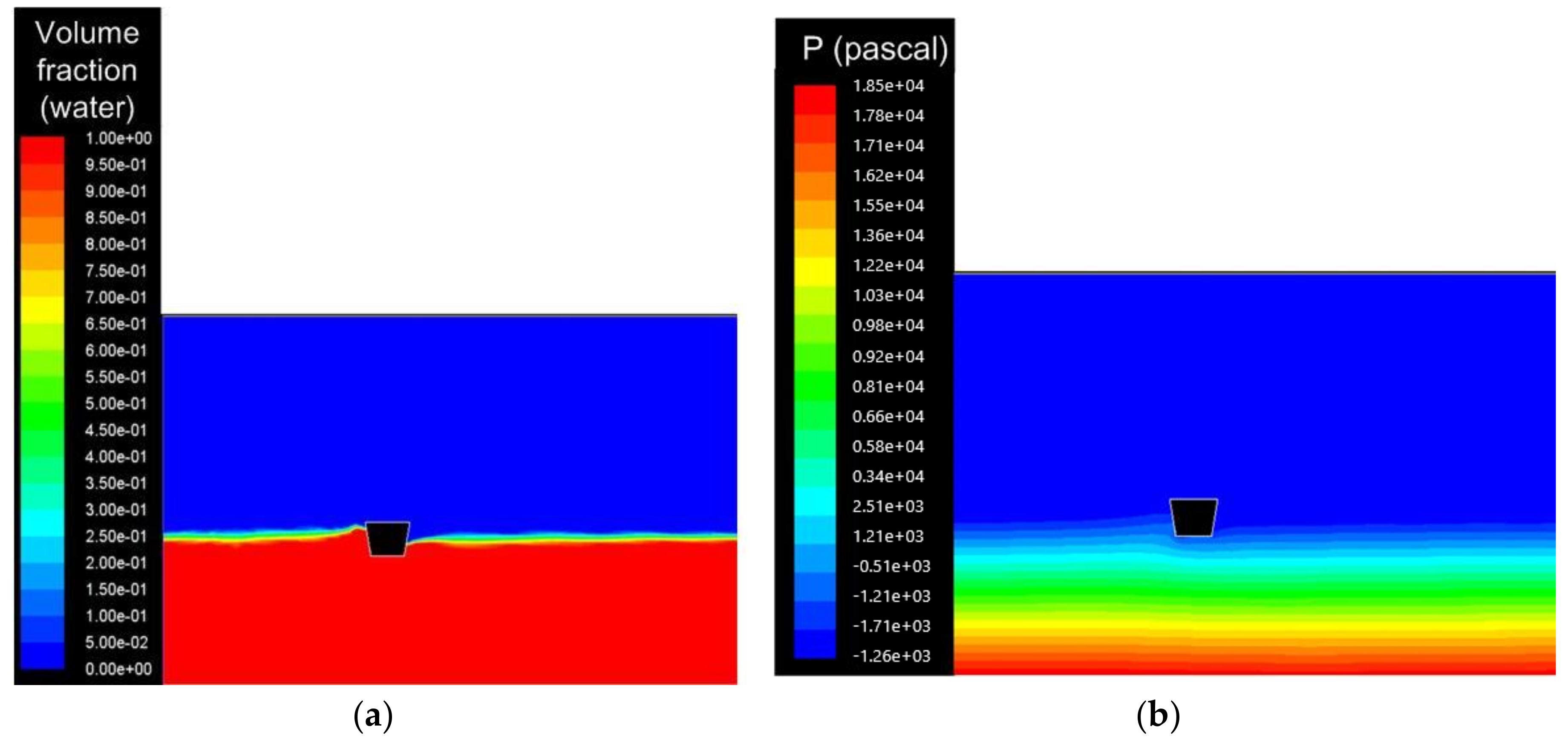
In the model analysis of the floater, when the time is 1.5 s, the contours of the volume fraction (water) and the static pressure of the floater are analyzed as shown in Figure 3a,b, respectively, where the blue section represents air and the red section represents water.
3. Analysis of TPMLG in D-DWEC
Many new linear generators for direct-drive energy conversion systems continue to attract attention and discussion as the exploitation of sea wave energy deepens. The air-gap flux density of generators with slotless structures is lower than that of slotted structures [15,16]. Meanwhile, Halbach PM arrays can increase the amplitude of the air-gap flux density better than R- and A-magnetized structures can [17]. In the current work, a TPMLG with an asymmetric slot structure topology and Halbach PM arrays is proposed and analyzed by FEA. The translator of the TPMLG is connected with the floater of the D-DWEC and driven by the floater directly.
3.1. Configuration of TPMLG
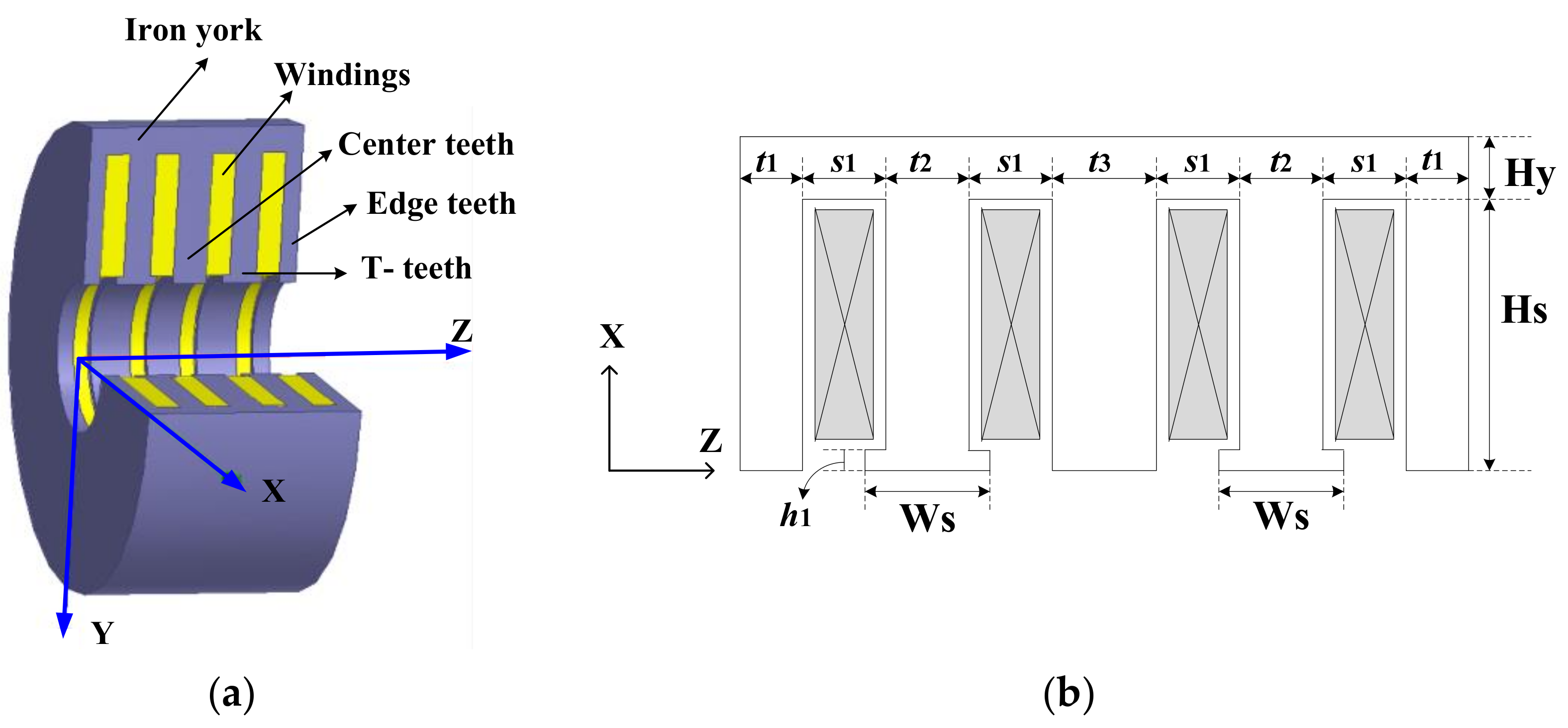
Figure 4 shows the stator structure of the TPMLG with an asymmetric slot. Figure 4a depicts a three-dimensional structure of the stator, which comprises windings, iron york, center teeth, edge teeth, and T-teeth. Figure 4b shows the main parameters of the stator. The asymmetric slot structure is applied to reduce the detent force and improve the air-gap flux density effectively. The four pie windings are connected to form a single phase to improve the amplitude of the output voltage.
Figure 5 shows the translator structure of the TPMLG. Figure 5a,b illustrate translators with traditional PMs. Figure 5c,d present translators with Halbach PM arrays. Figure 5c,d show that, unlike the translators with traditional PMs, those with the Halbach PM arrays have axial and radial magnetization PM structures.
A TPMLG with a symmetric slot structure is used for a comparative analysis with the TPMLG with an asymmetric slot structure. The translator structures and parameters and the power of the two generators are the same. By contrast, the stator structures and parameters differ. The key parameters of the two generators are listed in Table 2. In the dynamic characteristic analysis, loading a case at a constant velocity of 0.4 m/s is restricted.
3.2. Equation and Vector Diagram of TPMLG
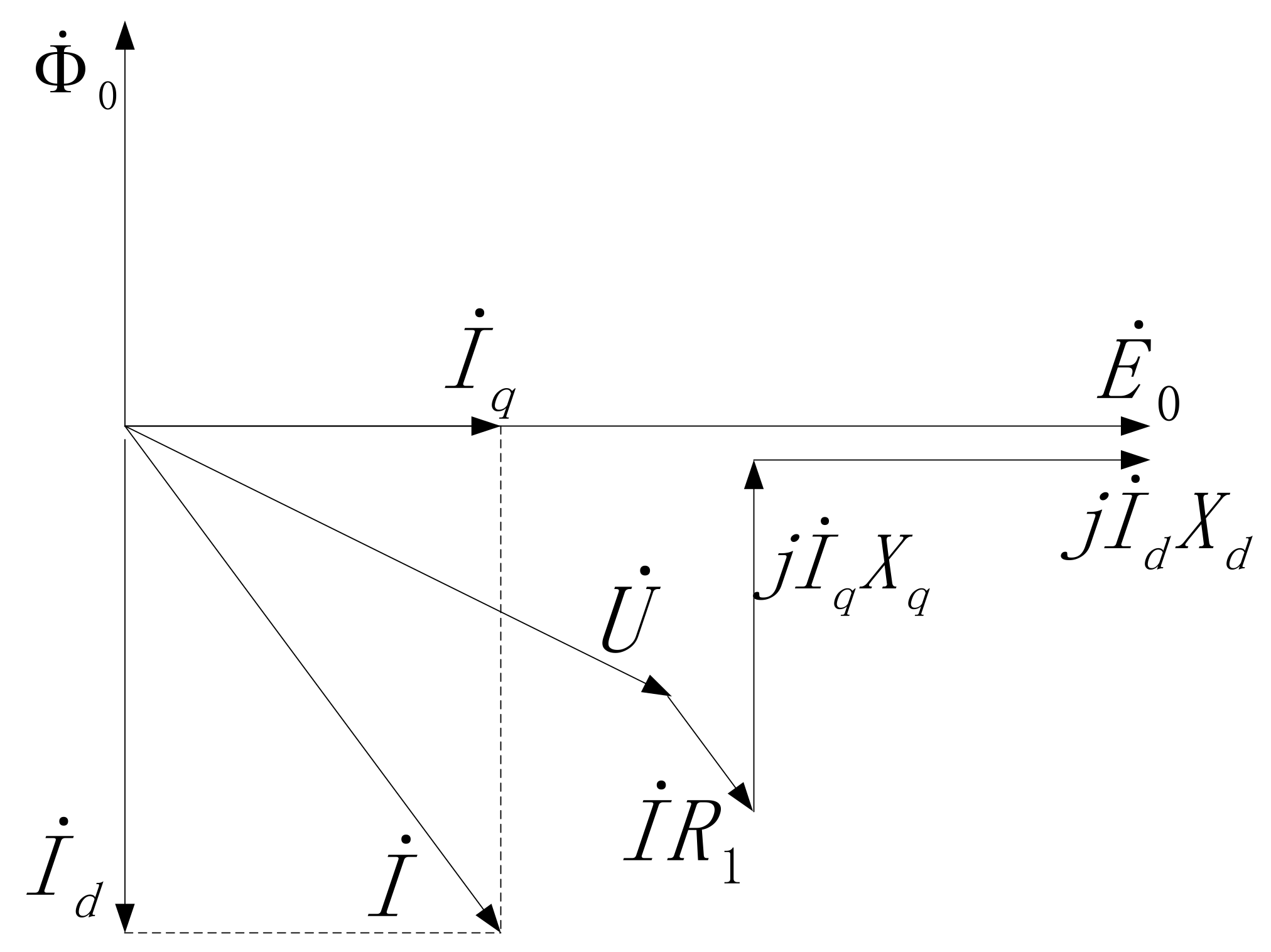
The proposed TPMLG is a machine with a surface-mounted PM, and the magnetic reluctances of the quadrature and direct axes are nearly the same. The equations and the vector diagram of the TPMLG are analyzed on the basis of the analysis method of the rotating PM synchronous motors.
The armature reaction magnetic motive force (MMF) is resolved into direct-axis and quadrature-axis MMFs when magnetic saturation is ignored. Then, the direct-axis and quadrature-axis components of the armature reaction flux are deduced. The direct-axis and quadrature-axis components of EMF (Ead and Eaq, respectively) are also derived. The excitation (E0) is produced by the major flux (Ф0) of the generator. Thus, the voltage equation of the TPMLG can be derived as follows:
where R1 is the winding resistance, X1 is the leakage reactance, U is the winding terminal voltage, and I is the winding armature current. The direct-axis and quadrature-axis components of the EMF are expressed as follows:
where Xad and Xaq are the direct-axis and quadrature-axis components of the generator reactance, respectively, and Id and Iq are the direct-axis and quadrature-axis components of the armature current, respectively. On the basis of Equations (6) to (8), the excitation E0 can be derived as follows:
where Xd and Xq are the direct-axis and quadrature-axis synchronous reactance, respectively. Xd and Xq are expressed as follows:
The vector diagram of the TPMLG, as shown in Figure 6, is based on the analysis procedure and Equations (6) to (11).
3.3. Magnetic Field Distribution
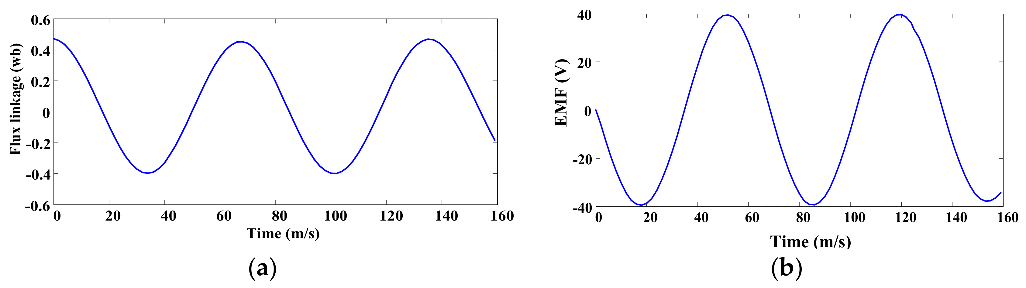
The static magnetic field distribution under no-load operation is depicted in Figure 7. The analysis of the dynamic characteristics, which is restricted to the no-load case at a constant velocity of 0.4 m/s, is shown in Figure 8. Figure 8a shows the flux linkage of the TPMLG, and Figure 8b illustrates the one-phase induced EMF waveform of the TPMLG. Figure 8b shows that a voltage peak value of 40 V is obtained.
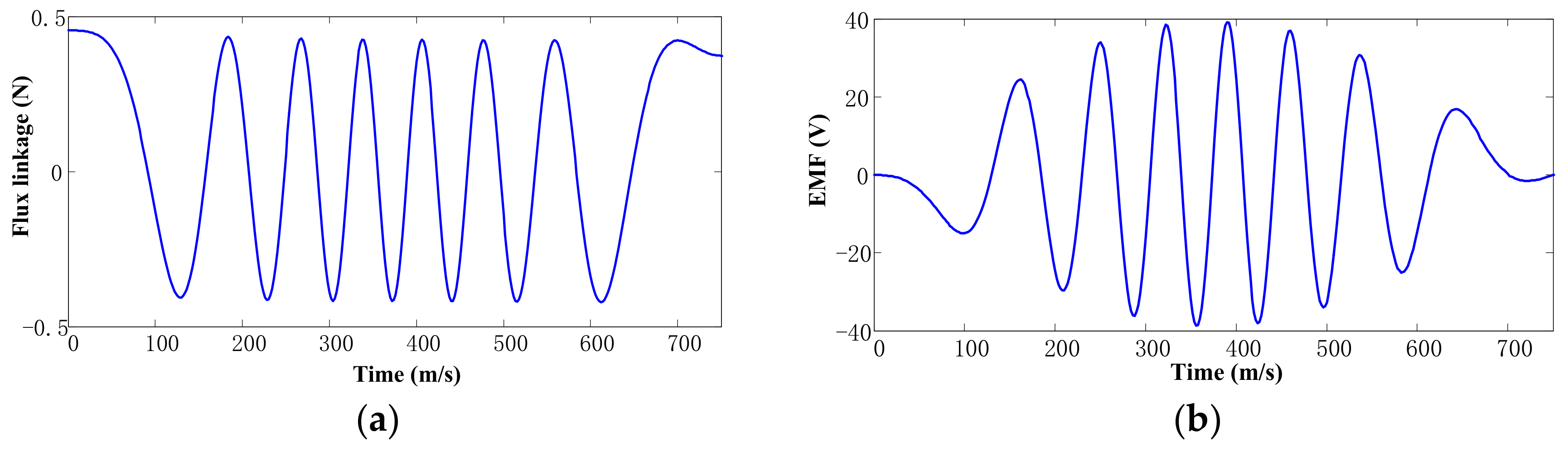
The flux linkage and EMF waveforms with time at a sine velocity of 0.4 sin (4πt/3) m/s are illustrated in Figure 9a,b, respectively. The period of sine velocity is 1500 ms; half of it is 750 ms, in which the velocity varies from 0 to 0.4 m/s. Figure 10 shows that the voltage peak value of the EMF waveform can reach 40 V.
3.4. Analysis of Detent Force
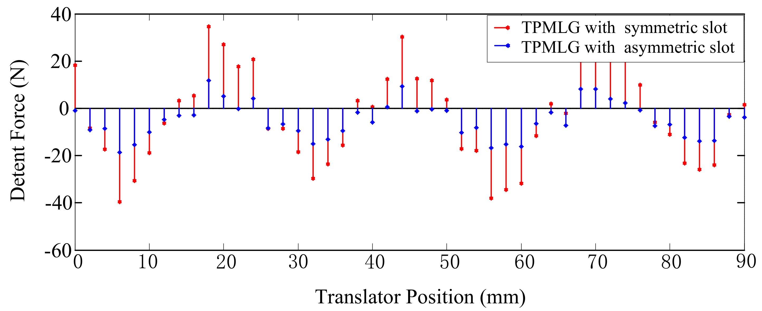
Detent force is an important parameter in linear generators, and its amplitude affects the stability and conversion efficiency of D-DWEC systems, especially at low speeds. This force comes from the unbalanced attractive forces between the stator teeth and PM structures, regardless of winding current. The detent force comprises end effect and cogging forces; the former comes from the attractive force between the stator edge teeth and the PM structure, and the latter originates from the attractive force between the stator middle teeth and the PM structure. Figure 10 depicts the detent force of the TPMLGs with asymmetric and symmetric slots. The detent force can be reduced from 40 to 8 N with the adoption of the asymmetric slot structure.
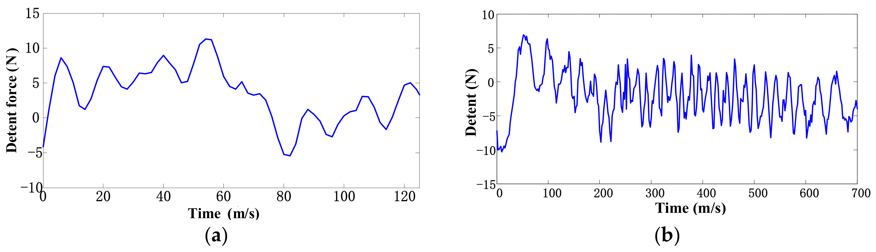
In the proposed design, an asymmetric slot structure and Halbach PM arrays are used in the TPMLG. Figure 11a shows that the fluctuation amplitude of detent force can be reduced to 15 N at a constant speed of 0.4 m/s. The fluctuation amplitude can be reduced to 18 N at a sine velocity of 0.4 sin (4πt/3) m/s, as shown in Figure 11b.
3.5. Power and Efficiency Analysis of TPMLG
When connecting with different resistance values of ohmic load, the output power of the generator is calculated as shown in Figure 12. The maximum output power is 41 W when the load is 7.2 Ω, and the output power decreases and then stabilizes with a gradually increasing load.
The efficiency of the TPMLG is calculated by the following expression:
where PG is the output power of the generator and PM is the input mechanical power of the generator. When the TPMLG runs with load, an electromagnetic force exists in the course of operation. When the speed of the generator is 0.4 m/s, the average value of the electromagnetic force is 133 N and the input mechanical power is 53.2 W. Figure 13 shows that the maximum output electrical power is 41 W. Thus, the maximum efficiency of the TPMLG is 77%, according to Expression (12).
4. Conversion Efficiency of D-DWEC
The conversion efficiency of the D-DWEC is calculated by the following expression:
where PG is the output electrical power of the generator in one wave period. Its computational process is described in Section 3.5. PW is the input power of the wave and calculated by Expression (14).
where E is the input wave energy in one wave period and comprises the kinetic energy of the wave (EK) and the potential energy of the wave (EP); T is the wave period. The input wave energy can be calculated by Expression (15).
In the analysis, the function of the wave surface is defined as follows:
where H is the wave height, ω is the angular frequency, k is the wave number, and x is the direction of the wave transmission.
EP is the average potential energy in one wave length and calculated by the following expression:
EK is the total kinetic energy in one wave length and calculated by the following expression:
where h is the water depth, λ is the wave length, g is the gravity constant, ρ is the density of water, ω is the angular frequency, and k is the wave number. u and v are the vertical and horizontal components of wave velocity and calculated by Expressions (19) and (20), respectively.
5. Experiment Analysis
To verify the optimal design of the generator, a full-scale model of the TPMLG with a symmetric slot structure is used in the experiment. Figure 13a–c show the stator, translator, and prototype of the TPMLG, respectively.
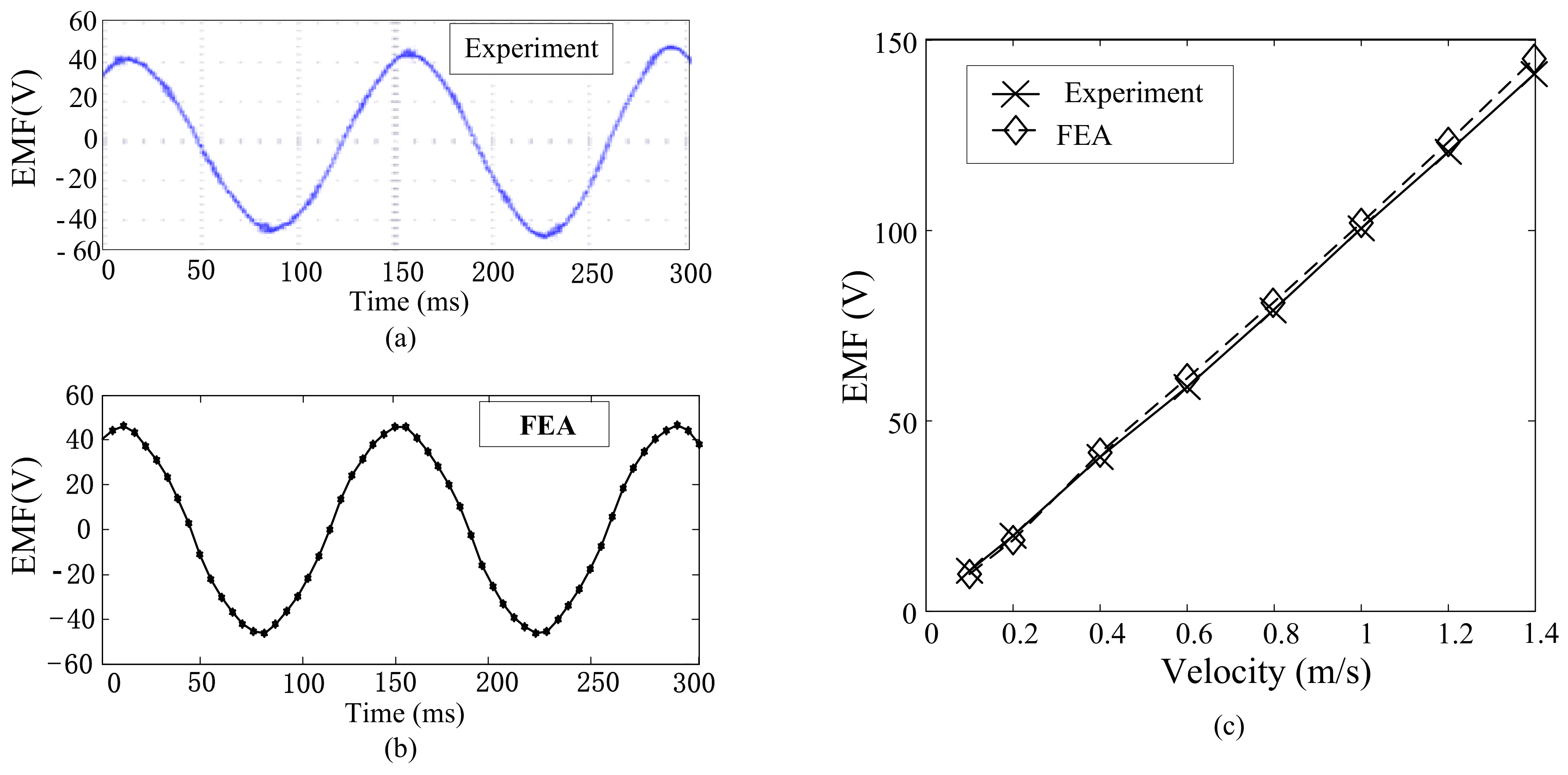
When the TPMLG runs at a constant velocity, its output EMF waveform can be obtained as shown in Figure 14. Figure 14a shows the EMF waveform, which is obtained through experiments at a constant velocity of 0.4 m/s, and Figure 14b shows the EMF waveform obtained through FEA at a constant velocity of 0.4 m/s. Figure 14c shows the comparison of the no-load EMF between FEA and the experiment at different velocities.
A D-DWEC experimental platform system that mainly includes a wave flume, support platform, TPMLG with symmetric slot structure, a full-scale model of cone frustum floater, ohmic load, linkage structure, and test equipment is developed, as shown in Figure 15, to verify the system operating performance.
The height and width of the wave flume in the experiment system are 1.3 and 1 m, respectively, and the depth of the water in the wave flume is set as 0.73 m. The floater of the full-scale model is used in the experiment system, and the structure size of the floater is shown in Table 1 (Section 2.3). Waves with different heights and periods can be developed from the push plate of the wave flume, and the motion stroke of the generator can be adjusted by the water depth of the floater in the wave flume. With different wave parameters, test results can be obtained in the experimental platform system.
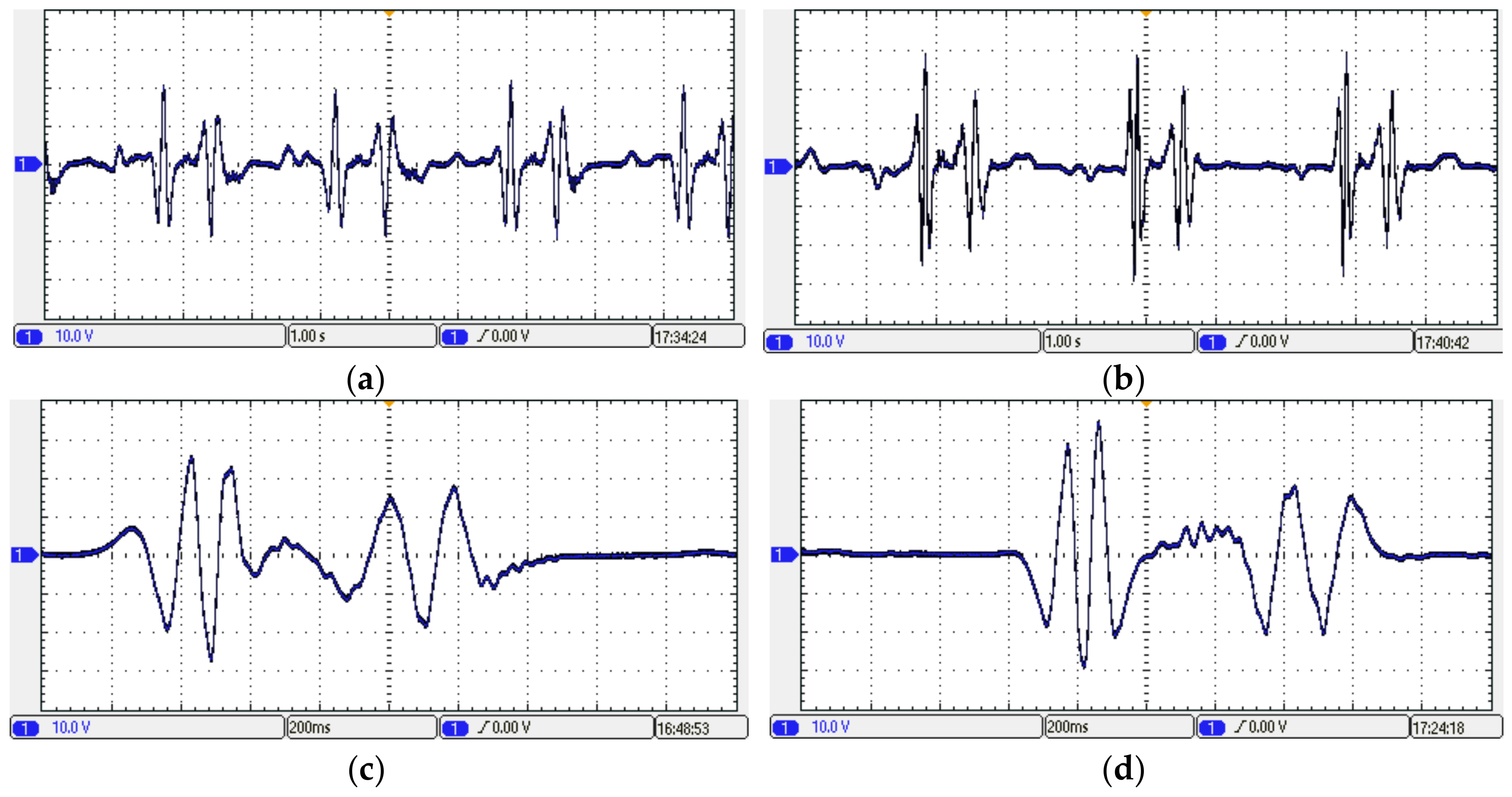
Figure 16a shows the one-phase output voltage waveform of the D-DWEC system that is obtained when the wave height is 0.15 m and the wave period is 1.5 s. Figure 16b depicts the one-phase output voltage waveform that is acquired when the wave height is 0.18 m and the wave period is 1.5 s. Figure 16c illustrates the one-phase output voltage waveform that is obtained when the wave height is 0.2 m and the wave period is 1.5 s. Figure 16d shows the one-phase output voltage waveform that is acquired when the wave height is 0.2 m and the wave period is 2 s.
The efficiency of the system conversion under different wave parameter conditions is calculated on the basis of the test result data of the experimental platform system using Expressions (6) to (10), as shown in Table 3. In the analysis, the wave period is a fixed value of 2 m. Table 3 shows that when the wave period T is a fixed value of 1.5 s, wave PW and the output power of the generator PG increase, and then the efficiency of the system conversion ηS does not increase. When the wave height H is a fixed value of 0.2 m, the output electrical power of the generator PG and the efficiency of the system conversion ηS increase, and then the input power of the wave PW does not increase. This is because the oscillation frequency of the floater system and the frequency of the wave conversion system have a large discrepancy.
6. Conclusions
A D-DWEC system applied on a wind and solar photovoltaic complementary energy generation platform is proposed. This system mainly comprises a TPMLG and a cone floater, which allow for steady operation and convenient installation. Moreover, a TPMLG with an asymmetric slot structure is proposed for the D-DWEC system. The magnetic field distribution, operation performance, and output efficiency are studied through FEA. Compared with the TPMLG with a symmetric slot structure, that with an asymmetric slot has lower detent force. Lastly, an experimental system is used to test the analysis results. The experiment shows that the D-DWEC system model has high conversion efficiency, small detent force fluctuation, and high energy density. Moreover, good performance is achieved by the wave energy system in the wind and solar photovoltaic complementary energy generation platform.
Acknowledgments
This work was supported by the Postdoctoral Foundation of China under Grant 2015M570396, Jiangsu Province Natural Science Foundation of Youth under Grant BK20150115, Natural Science Foundation of China under Grant 41576096, and Natural Science Foundation incubation project under Grant JIT-fhxm-201702.
Author Contributions
All the authors exerted best efforts to ensure that the paper becomes qualified for publishing. Haitao Yu and Jing Zhang designed and supervised the work. Jing Zhang and Zhenchuan Shi conducted the simulations and experiments.
Conflicts of Interest
The authors declare no conflicts of interest.
Abbreviations
The following abbreviations are used in this manuscript:
| WEC | wave energy converter |
| D-DWEC | direct-drive wave energy conversion |
| TPMLG | tubular permanent magnet linear generator |
| CFD | computational fluid dynamics |
| FEA | finite element analysis |
| OWC | oscillating water column |
| AWS | Archimedes wave swing |
| RANS | Reynolds Averaged Navier Stokes |
| PM | permanent magnet |
| PTO | power take-off |
| EMF | electromotive force |
| THD | total harmonic distortion |
| NdFeB | neodymium iron boron |
| VOF | volume of fluid method |
| MMF | magnetic motive force |
References
- Melikoglu, M. Current status and future of ocean energy sources: A global review. Ocean Eng. 2018, 148, 563–573. [Google Scholar] [CrossRef]
- Drew, B.; Plummer, A.R.; Sahinkaya, M.N. A review of wave energy converter technology. Proc. Inst. Mech. Eng. Part A J. Power Energy 2009, 223, 887–902. [Google Scholar] [CrossRef]
- Polinder, H.; Mattia, S. Wave energy converters and their impact on power systems. In Proceedings of the International Conference on Future Power Systems, Amsterdam, The Netherlands, 18 November 2005; pp. 1–9. [Google Scholar]
- Ozkop, E.; Altas, I.H. Control, power and electrical components in wave energy conversion systems: A review of the technologies. Renew. Sustain. Energy Rev. 2017, 67, 106–115. [Google Scholar] [CrossRef]
- Ahn, K.K.; Truong, D.Q.; Tien, H.H.; Yoon, J., II. An innovative design of wave energy converter. Renew. Energy 2012, 42, 186–194. [Google Scholar] [CrossRef]
- Gao, Y.; Shao, S.; Zou, H.; Tang, M.; Xu, H.; Tian, C. A fully floating system for a wave energy converter with direct-driven linear generator. Energy 2016, 95, 99–109. [Google Scholar] [CrossRef]
- Brekken, T.K.A.; von Jouanne, A.; Han, H.Y. Ocean wave energy overview and research at Oregon State University. In Proceedings of the Power Electronics and Machines in Wind Applications, Lincoln, NE, USA, 24–26 June 2009; IEEE: New York, NY, USA. [Google Scholar]
- Ekström, R.; Ekergård, B.; Leijon, M. Electrical damping of linear generators for wave energy converters—A review. Renew. Sustain. Energy Rev. 2015, 42, 116–128. [Google Scholar] [CrossRef]
- Polinder, H.; Mecrow, B.C.; Jack, A.G.; Dickinson, P.G.; Mueller, M.A. Conventional and TFPM Linear Generators for Direct-Drive Wave Energy Conversion. IEEE Trans. Energy Convers. 2005, 20, 260–267. [Google Scholar] [CrossRef]
- Mueller, M.A. Electrical generators for direct drive wave energyconverters. IET Gener. Transm. Distrib. 2002, 149, 446–456. [Google Scholar] [CrossRef]
- Prudell, J.; Stoddard, M.; Amon, E.; Brekken, T.K.A.; Jouanne, A. A permanent-Magnet Tubular Linear Generator for Ocean Wave Energy Conversion. IEEE Trans. Ind. Electron. 2010, 46, 2392–2400. [Google Scholar] [CrossRef]
- Eriksson, M.; Isberg, J.; Leijon, M. Hydrodynamic modelling of a direct drive wave energy converter. Int. J. Eng. Sci. 2004, 43, 1377–1387. [Google Scholar] [CrossRef]
- Serena, A.; Molinas, M.; Cobo, I. Design of a Direct Drive Wave Energy Conversion System for the Seaquest Concept. Energy Procedia 2012, 20, 271–280. [Google Scholar] [CrossRef]
- Feng, N.; Yu, H.; Hu, M.; Huang, L.; Shi, Z. A Study on a Linear Magnetic-Geared Interior Permanent Magnet Generator for Direct-Drive Wave Energy Conversion. Energies 2016, 9, 487. [Google Scholar] [CrossRef]
- Ruoho, S.; Arkkio, A. Mixed-grade pole design for permanent magnet synchronous machines. In Proceedings of the International Aegean Conference on Electrical Machines and Power Electronics, Bodrum, Turkey, 10–12 September 2007. [Google Scholar]
- Leijon, J.; Sjölund, J.; Ekergård, B.; Boström, C.; Eriksson, S.; Temiz, I.; Leijon, M. Study of an Altered Magnetic Circuit of a Permanent Magnet Linear Generator for Wave Power. Energies 2018, 11, 84. [Google Scholar] [CrossRef]
- Shen, Y.; Zhu, Z.Q. Analysis of Electromagnetic Performance of Halbach PM Brushless Machines Having Mixed Grade and Unequal height of Magnets. IEEE Trans. Magn. 2013, 49, 1461–1469. [Google Scholar] [CrossRef]
Figure 1.
Direct-drive wave energy conversion system.
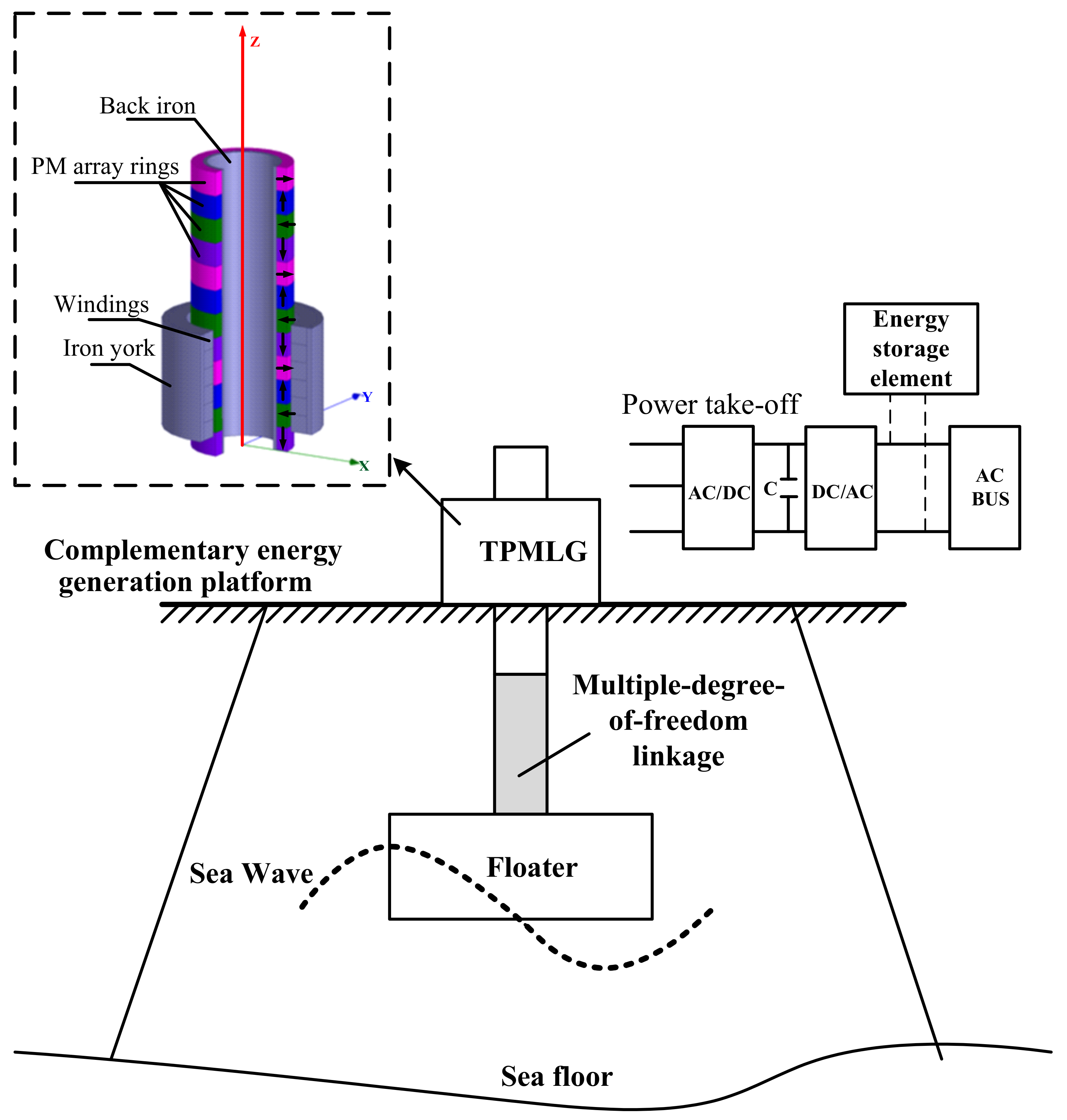
Figure 2.
Cone frustum floater model.
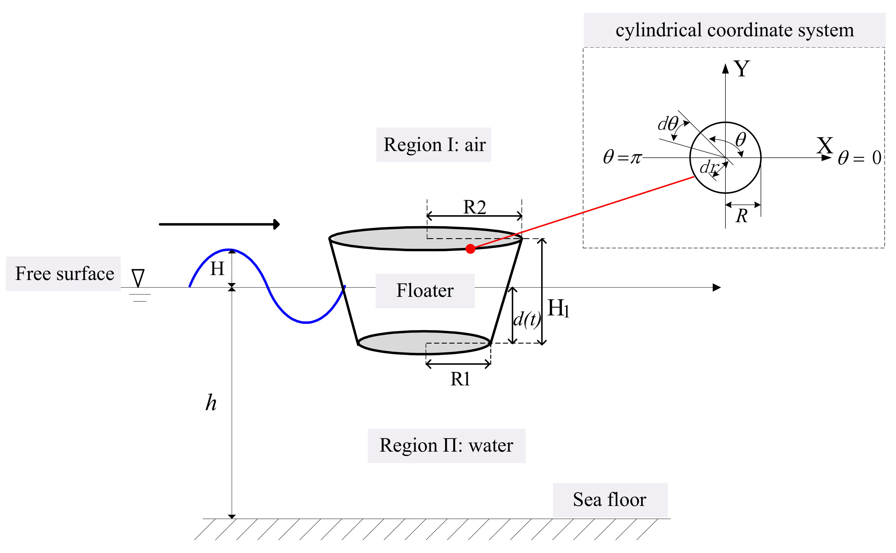
Figure 3.
Fluid volume fraction and pressure distributions of the cone frustum floater: contours of (a) volume fraction (water) and (b) static pressure.
Figure 3.
Fluid volume fraction and pressure distributions of the cone frustum floater: contours of (a) volume fraction (water) and (b) static pressure.

Figure 4.
Stator structure of the TPMLG: (a) three-dimensional structure and (b) main parameters.

Figure 5.
Structures of translators: (a) translator with traditional PMs and (b) its two-dimensional structure and a (c) translator with Halbach PM arrays and (d) its two-dimensional structure.
Figure 5.
Structures of translators: (a) translator with traditional PMs and (b) its two-dimensional structure and a (c) translator with Halbach PM arrays and (d) its two-dimensional structure.
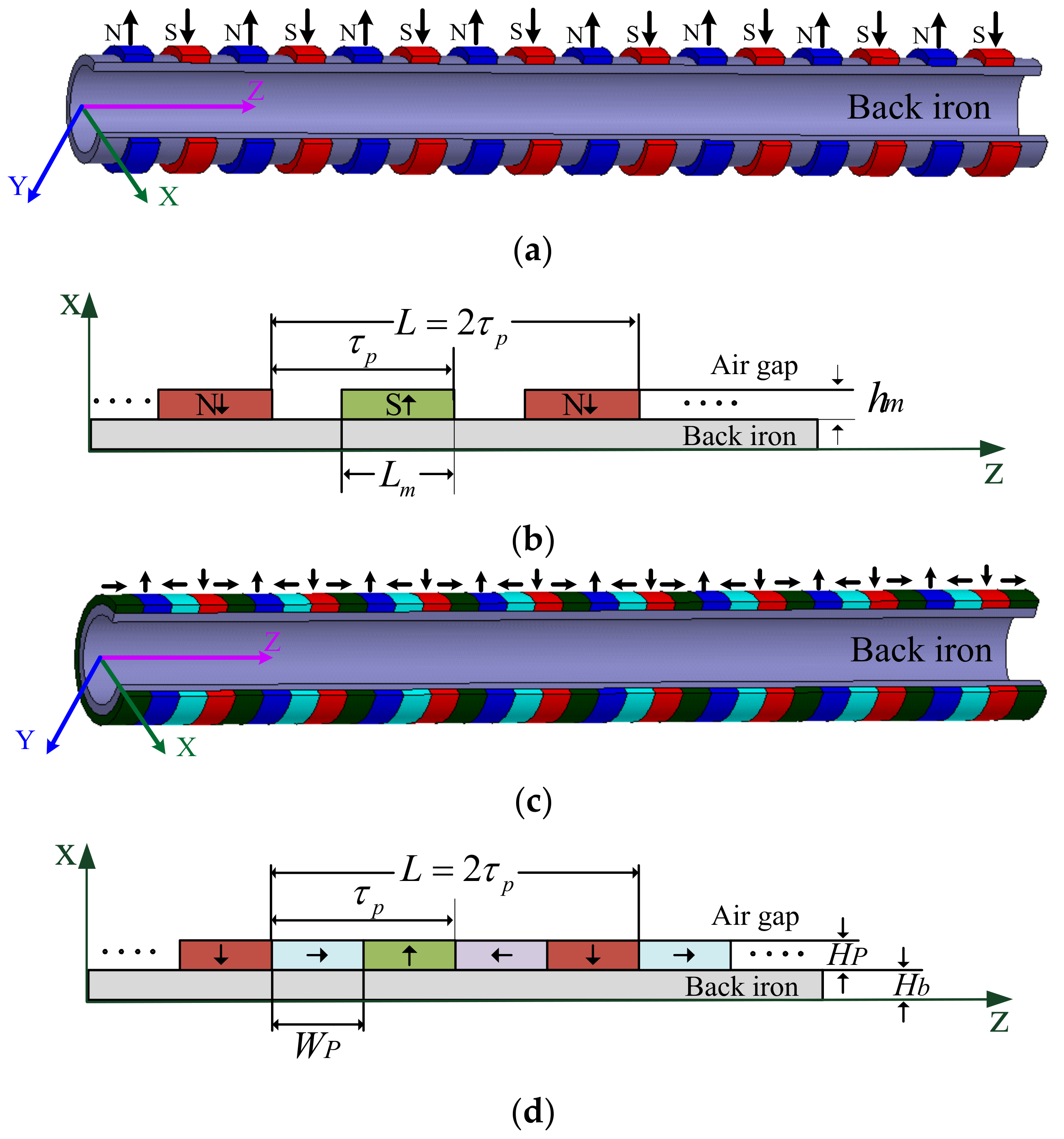
Figure 6.
Vector diagram of the TPMLG.

Figure 7.
Magnetic field distribution of the TPMLG under no-load condition.
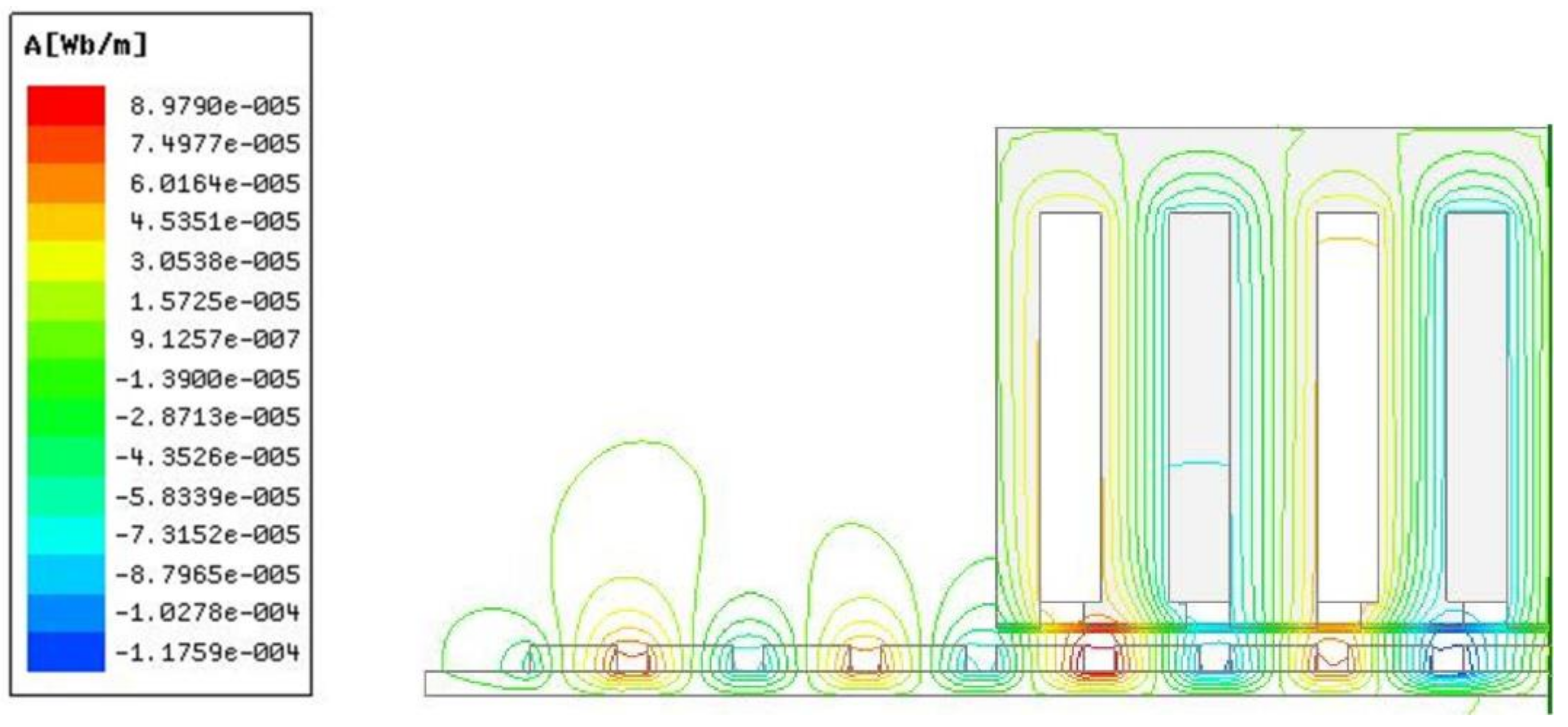
Figure 8.
TPMLG waveforms at constant velocity: (a) flux linkage and (b) EMF waveforms.

Figure 9.
TPMLG waveforms at sine velocity: (a) flux linkage and (b) EMF waveforms.

Figure 10.
Detent force of the TPMLGs with asymmetric and symmetric slots.

Figure 11.
Detent force curves at (a) constant and (b) sine velocities.

Figure 12.
Output power with different ohmic loads.

Figure 13.
TPMLG with a symmetric slot structure: (a) stator, (b) translator, and (c) prototype.
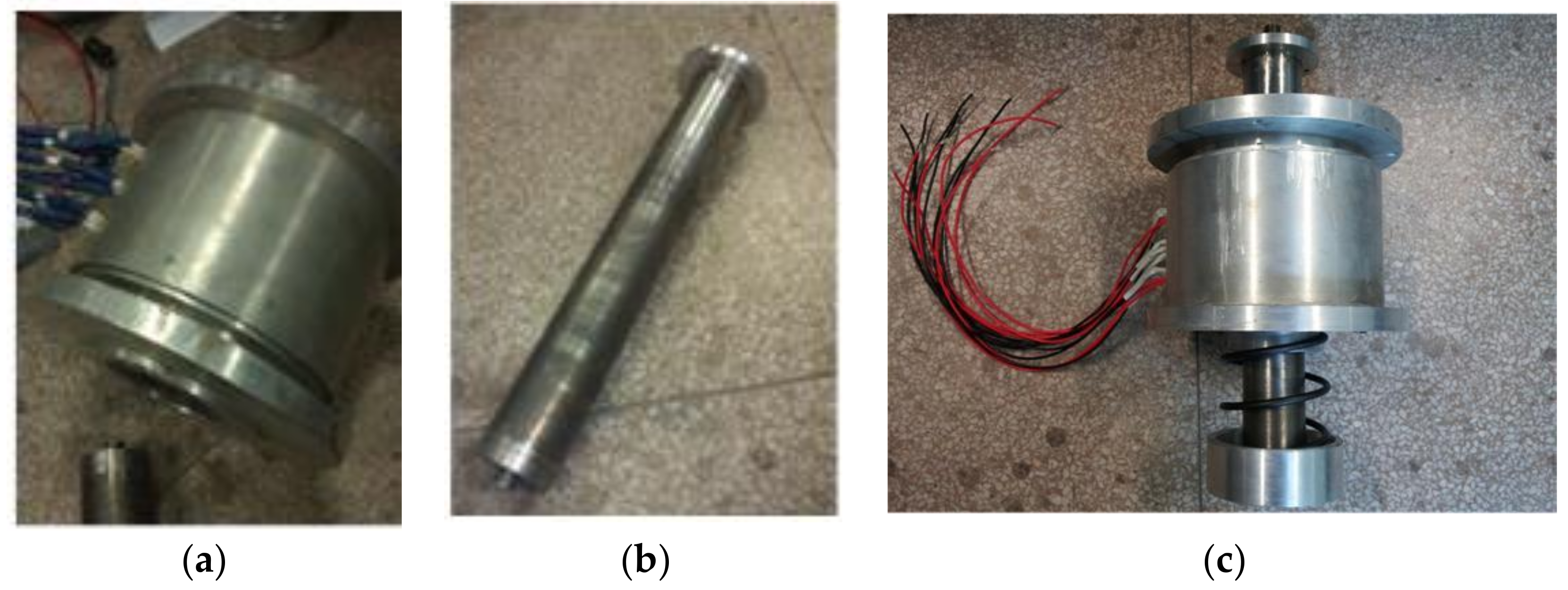
Figure 14.
EMF waveforms at constant and varying velocities: (a) through experiment at velocity of 0.4 m/s, (b) through FEA at velocity of 0.4 m/s, and (c) waveforms at different velocities.
Figure 14.
EMF waveforms at constant and varying velocities: (a) through experiment at velocity of 0.4 m/s, (b) through FEA at velocity of 0.4 m/s, and (c) waveforms at different velocities.

Figure 15.
D-DWEC experiment system platform.
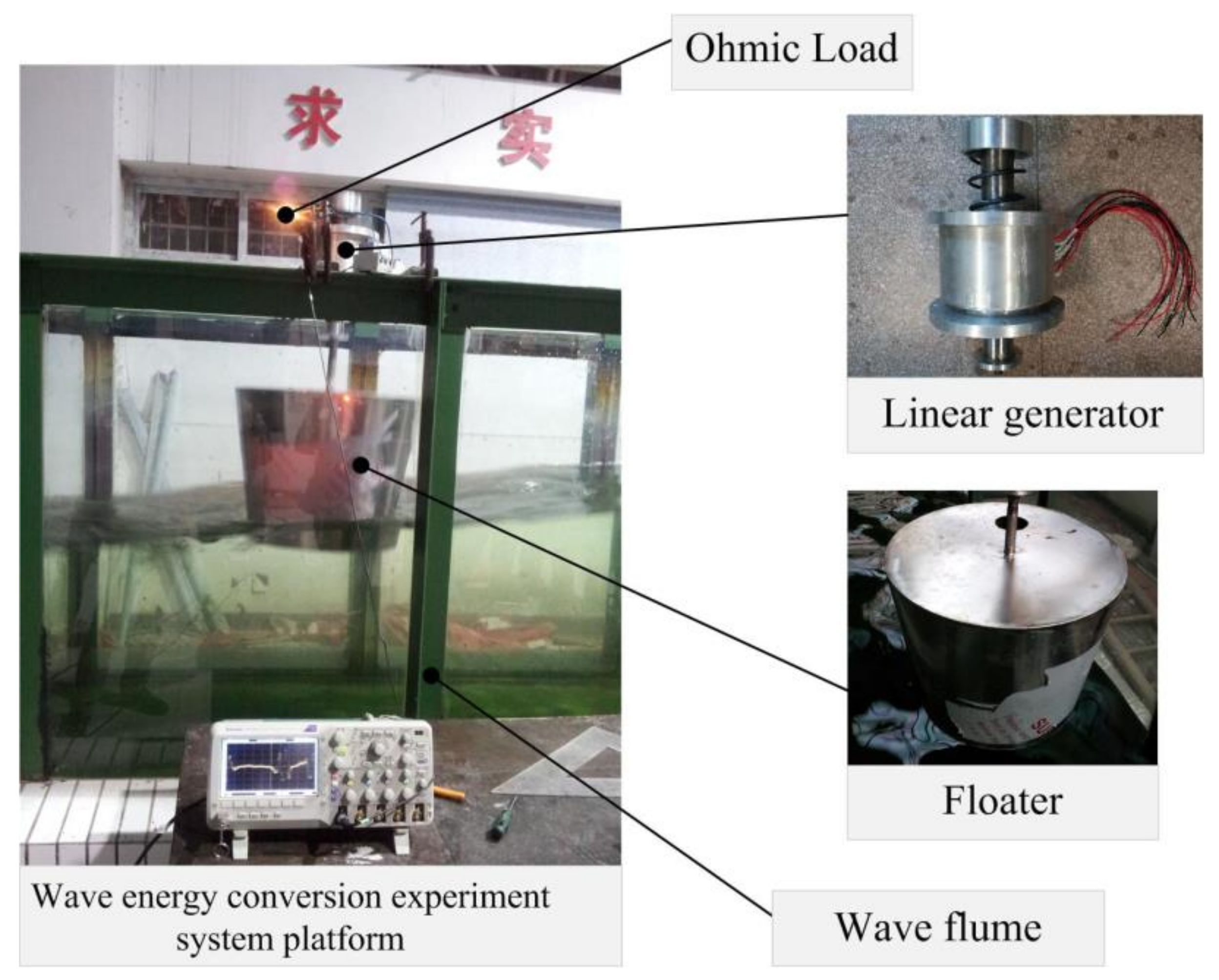
Figure 16.
Output voltage waveform of the D-DWEC system. (a) (1 s/div, 10.0 V/div), (b) (1 s/div, 10.0 V/div), (c) (0.2 s/div, 10.0 V/div), and (d) (0.2 s/div, 10.0 V/div).
Figure 16.
Output voltage waveform of the D-DWEC system. (a) (1 s/div, 10.0 V/div), (b) (1 s/div, 10.0 V/div), (c) (0.2 s/div, 10.0 V/div), and (d) (0.2 s/div, 10.0 V/div).

Table 1.
Parameters of the cone frustum.
| Item | Symbol | Value | Item | Symbol | Value |
|---|---|---|---|---|---|
| Floater height (m) | H1 | 0.45 | Wave velocity (m/s) | c | 1.00 |
| Underwater depth (m) | d(t) | 0.25 | Wave length (m) | λ | 2.00 |
| Bottom radius (m) | R1 | 0.225 | Wave height (m) | H | 0.20 |
| Top radius (m) | R2 | 0.30 | Water depth (m) | h | 5.00 |
| Wave Period (s) | T | 2.00 | Lift force (N) | FL | 1074.48 |
| Water density (kg/m3) | ρ | 1.25 | Viscous force (N) | FV | 12.04 |
| Kinetic viscosity (pa.s) | μ | 1.7894 | Total force (N) | FT | 1086.52 |
Table 2.
Basic parameters of the TPMLGs with asymmetric and symmetric slots.
| TPMLG with an Asymmetric Slot | TPMLG with a Symmetric Slot | ||||
|---|---|---|---|---|---|
| Length of PMs (mm) | Hp | 3 | Length of PMs (mm) | Hp | 3 |
| Width of PMs (mm) | Wp | 10 | Width of PMs (mm) | Wp | 10 |
| Length of air gap (mm) | Hg | 2 | Length of air gap (mm) | Hg | 2 |
| Pole pitch (mm) | τp | 20 | Pole pitch (mm) | τp | 20 |
| Length of back iron (mm) | Hb | 3 | Length of back iron (mm) | Hb | 3 |
| Height of slot (mm) | Hs | 48 | Height of slot (mm) | Hs | 48 |
| York height of stator (mm) | Hy | 10 | York height of stator (mm) | Hy | 10 |
| Height of T-teeth edge (mm) | h1 | 3 | Width of teeth (mm) | Wp | 8.5 |
| Width of slot (mm) | s1 | 7 | Width of slot (mm) | s2 | 6 |
| Width of edge teeth (mm) | t1 | 5 | Length of stator (mm) | LS | 64 |
| Width of center teeth (mm) | t3 | 10 | Stator winding turns per coil | N | 60 |
| Width of T-teeth (mm) | t2 | 8 | Number of slots | NS | 4 |
Table 3.
System conversion efficiency.
| Wave Period T (s) | Wave Height H (m) | Input Power of Wave PW (W) | Output Power of Generator PG (W) | Efficiency of System Conversion ηS (%) |
|---|---|---|---|---|
| 1.5 | 0.15 | 36.75 | 12.45 | 33.87 |
| 1.5 | 0.18 | 52.92 | 17.4 | 32.87 |
| 1.5 | 0.20 | 65.33 | 19.44 | 29.75 |
| 1.7 | 0.20 | 57.64 | 25.6 | 44.41 |
| 2.0 | 0.20 | 49 | 28.8 | 58.77 |
© 2018 by the authors. Licensee MDPI, Basel, Switzerland. This article is an open access article distributed under the terms and conditions of the Creative Commons Attribution (CC BY) license (http://creativecommons.org/licenses/by/4.0/).
Share and Cite
MDPI and ACS Style
Zhang, J.; Yu, H.; Shi, Z. Design and Experiment Analysis of a Direct-Drive Wave Energy Converter with a Linear Generator. Energies 2018, 11, 735. https://doi.org/10.3390/en11040735
AMA Style
Zhang J, Yu H, Shi Z. Design and Experiment Analysis of a Direct-Drive Wave Energy Converter with a Linear Generator. Energies. 2018; 11(4):735. https://doi.org/10.3390/en11040735
Chicago/Turabian StyleZhang, Jing, Haitao Yu, and Zhenchuan Shi. 2018. "Design and Experiment Analysis of a Direct-Drive Wave Energy Converter with a Linear Generator" Energies 11, no. 4: 735. https://doi.org/10.3390/en11040735
Note that from the first issue of 2016, this journal uses article numbers instead of page numbers. See further details here.