Movement Boundary Shape of Overburden Strata and Its Influencing Factors

1
School of Mines, China University of Mining and Technology, Xuzhou 221116, China
2
State Key Laboratory of Coal Resources and Safe Mining, China University of Mining and Technology, Xuzhou 221116, China
3
Department of Mining Engineering, Colorado School of Mines, 1600 Illinois street, Golden, CO 80401, USA
4
College of Mining and Safety Engineering, State Key Laboratory of Mining Disaster Prevention and Control Co-founded by Shandong Provence and the Ministry of Science and Technology, Shandong University of Science and Technology, Qingdao 266590, China
*
Author to whom correspondence should be addressed.
Energies 2018, 11(4), 742; https://doi.org/10.3390/en11040742
Submission received: 2 March 2018
/
Revised: 15 March 2018
/
Accepted: 20 March 2018
/
Published: 24 March 2018
Abstract
:Strata movement boundary is not only a parameter for the prediction of overburden strata movement and deformation but also a key index of setting shafts, roadways and protective coal pillars. Based on physical and mechanical properties of rock mass, the overburden strata are divided into bedrock and unconsolidated stratum. By means of theoretical analysis, physical simulation and numerical simulation, this paper studies the movement boundary shapes of bedrock and unconsolidated stratum, builds fitting equations of movement boundary of the two, analyzes the influence of key strata (KS) on the shape of strata movement boundary, and determines the principle of setting protective coal pillars. The results show that the movement boundaries of bedrock and unconsolidated strata are located at the outside of coal mining boundary. They are concave-upward power function curves that cannot be merged into a smooth one due to their different mechanisms of movement and deformation. The movement boundary of bedrock can approximate a straight line when lithology of the overburden is relatively uniform with thin strata in different positions; the surface movement boundary extends when the overburden has thick and stiff KS that are common in deeply buried coal seam. Therefore, the width of protective coal pillar is small if the movement boundary is regarded as a straight line. According to the curve movement boundary, the protective coal pillar for the passenger roadway of Panel 31010 of Pingdingshan No.1 mine is at least 99.4 m in width, larger than the designed one, which is the actual reason for its deformation and breakage.
1. Introduction
Energy resource is the basis for human survival and energy exploitation has made an important contribution to the development of national economy. However, most underground energy exploitation will lead to roof caving, overburden fracturing and surface subsidence, resulting in environmental damage and roadway convergence etc. [1,2,3]. Therefore, it is especially important to study the strata movement caused by coal mining. Nevertheless, in many cases, the protection of ground buildings and roadways only requires the determination of overburden movement boundary, namely the delimitation of the risk of collapse, rather than the movement and deformation values of the whole areas affected.
The overburden movement boundary is foundation and precondition of the prediction of strata movement and deformation as well as the protection of houses outside the mining area and underground roadway and structures. Traditionally, the strata movement boundary is considered to be a straight line [4,5]. According to this viewpoint, Shu and Bhattacharyya established the mathematical expression of the movement and deformation relationship between surface and the overburden, but their prediction results were not in line with actual measured data commendably [6]. With the consideration of the straight movement boundary, the width of protective coal pillar for blind shafts of Dahuangshan mining area in Xuzhou City, China was designed. However, the walls of shafts cracked and fell off during the mining Panels 3303 and 3304 [7]. To protect DingWu-3 passenger roadway in Pingdingshan No.1 mine, a 90-m-wide protective coal pillar was designed in its floor, the Wu-10 coal seam, on the basis of straight movement boundary, but severe deformation still occurred at the passenger roadway during stoping [8]. These practices suggest that the movement boundary may not be a straight line. Actually, different stress levels and distribution among rock strata with various heights lead to varied movement and deformation gradients of strata in different positions after the excavation of coal seam [8]. The normal direction of the movement boundary is in keeping with the direction of gradient, so the movement boundary is extending in changing directions rather than in a straight line from coal seam to surface.
The surface movement boundary has been deeply studied because of its close connection with the living environment, especially in densely populated mining area with villages, industrial squares, railway lines, and garbage dumps on the ground. For protecting these surface structures, much research has been done on it and the width of protective coal pillars [9,10,11,12,13,14]. In addition, the relationship between surface movement boundary and lithology of the overburden is also a focus [15,16,17,18,19]. Research methods of strata movement boundary are limited, and field measurements can only be carried out by arranging boreholes at different surface positions. However, the dynamic influence boundary, rather than the static boundary, is measured, which is unconvincing with few observation data [20]. Gao and Shen [21] found that the movement boundary was not a straight line but a convex-upward power function curve by numerical simulation. The results of similar simulation experiment by Dai et al. [22] revealed that the movement boundary of bedrock was a convex-upward curve and concave-upward curve in the open-off cut side and the stop line side, respectively, while that of Wu et al. [23] demonstrated that the movement boundary is a S-shaped curve. On the basis of probability integral method, Yu [24] made an assumption that major influence angle in strata were related to the position and buried depth, obtaining the relation between the radius of influence of underground rock mining and that of surface mining. According to the relation, there were two types of curves of strata movement boundary varying with parameters, namely, upward-concave curve and upward-convex curve. At present, little research on strata movement boundary has been conducted. The existing research has not provided exact explanation of movement boundary shapes of strata, let alone distinguish those of bedrock and unconsolidated stratum that are greatly different in physical and mechanical properties.
In this paper, the overburden is first divided into bedrock and unconsolidated stratum whose movement boundary shapes are analyzed by establishing different mechanical models adopting continuum mechanics and mechanics of granular media, respectively, and then the influences of thick and hard rock strata on the size of movement boundary are focused on. Next, the empirical models of movement boundaries of bedrock and unconsolidated stratum are offered. Besides, the correctness of the models is analyzed qualitatively by physical simulation and numerical simulation. Finally, the principle of designing protective coal pillars is determined according to the movement boundary shape, and its reliability is proved by a case.
2. Theoretical Model
The overburden strata on the coal seam usually include bedrock and unconsolidated stratum (topsoil), as shown in Figure 1. The laboratory test indicates that specimens of the two are greatly different in the physical and mechanical properties. In addition, the on-site observation and practice reveal that the features of unconsolidated stratum are similar to that of granules, while bedrock is hard and compact, close to continuum. Therefore, the study of the overburden movement boundary should cover two parts: bedrock and unconsolidated stratum, and particles of the latter move after the deformation of the interface of bedrock top.
The simplest methods of forecasting deformations are methods based on empirical formulas [4], defined for different ways of exploitation and the position of the excavation and the selected field of a given size. Models—prognostic theories can be divided into four groups: geometric-integral, stochastic, based on rock mass (continuous medium) and numerical models based on discretization of the medium. Geometric-integral theories referring to asymptotic deformations assume the existence of the so-called the influence function, which determines the distribution of the decreases caused by the elemental (about infinitesimal volume) depending on the horizontal distance of the point of the object from it. The reduction due to the selection of a finite field is the sum of the decreases from all elementary exploitation of this field. Horizontal dislocations are described on the basis of additional assumptions defining mutual relations with depressions. This group of methods includes the theories of Knothe-Budryk [25] and Ehrhardt-Sauer [26]. They differ mainly in the shape of the influence function. Stochastic models treat a rock mass as a center subject to random laws (Litwiniszyn theory). So far, they have not found practical applications due to the complexity of the description and a large number of parameters. Models based on rock mass mechanics—the mechanics of continuous medium (on differential equations) are most often used to locally describe the impact of mining excavations in the rock mass in their small surroundings, which results from the need to simplify the rock mass structure and interactions in order to obtain analytical solutions (Sałustowicz’s work [27]).
2.1. Movement Boundary Shape of Bedrock
Any stratum of the overburden is treated as a homogeneous isotropic plane strain beam, and meanwhile the height, as well as mechanical properties of it, is regarded to be constant axially. The top and bottom surfaces of it are influenced by friction of opposite direction. The friction coefficient, supporting force and loads of both surfaces are approximately equal, so the effect of friction together with axial force can be ignored. The subsidence of the beam is free from the impact of the uniformly distributed loads at its upper part because they have already existed in the process of sediment. Therefore, the beam is only affected by end bending moment and shear force, as shown in Figure 2. Assuming that the deformation of foundation conforms to Winkler’s assumption, the differential equation of the beam is as follow:
where and are the elastic modulus and the section moment of inertia of the ith stratum, respectively; is the comprehensive elastic modulus of the foundation; is the distance from the ith stratum to the coal floor. , then Equation (1) is:
The general solution of the fourth order ordinary differential Equation (2) is:
There is a boundary condition at infinity due to the limited influence of coal mining. From Equation (3), , so Equation (3) becomes:
According to the relationship between the internal force and the beam subsidence:
The boundary condition corresponding to the origin of coordinates is , . They are introduced into Equation (5) to obtain the equation of the beam subsidence expressed by boundary conditions:
Trigonometrical transform is done on Equation (6) to get:
where is the initial phase of the displacement wave, . Based on Equation (7), under the action of bending moment and shear force, vertical displacement of strata is an attenuation cosine function in accordance with the law of negative exponent function , and it can be neglected after half a cycle.
Equation (7) is the subsidence of the ith stratum under its own loads without the combination of lower strata subsidence. When combining, the subsidence of the ith stratum is:
The subsidence range of strata is calculated by viewing subsidence of the first solution as the movement boundary of the ith stratum. Then
According to the summation principle of trigonometric functions, the angular frequency of a trigonometric function after the addition of trigonometric functions with different angular frequency is that of the smallest one before the sum, i.e., β = min βk (k = 1…i). With the rise of strata level, β is decreasing, so βi < βi−1, and then β = βi. At this point, Equation (9) is:
According to the geometric relationship between the angle of draw γi and the depth Hi of the ith stratum (see Figure 2), the difference between angles of draw of two adjacent strata is as follows:
where is the initial phase of ith stratum with the combination of lower strata subsidence. The relationship between βi and Hi can be simplified as . βi is brought into Equation (11) to gain:
Equation (12) can be simplified to get:
where is the maximum value of the two. The subsidence of the overburden on the mining boundary is in line with the cosine function of initial phase, and it keeps increasing as the calculated strata approach the surface due to the combination of subsidence. As a result, keeps falling, so . From Equation (13), < 0, so .
The relationship between the angle of draw and the curve pattern is shown in Figure 3. If CD is the strata movement boundary, the angle of draw will not change with different strata level when points C and O coincide, so the movement boundary is not a straight line. If the curve DAC is the strata movement boundary, it can be seen from Figure 3 that . For the convex-upward curve DAC, the closer the strata to the surface after a certain stratum, the greater the angle of draw, so the movement boundary is not a convex-upward curve. If the curve DBC is the strata movement boundary, it can be found that . For the concave-upward curve DBC, the closer the strata to the surface, the smaller the angle of draw, so the movement boundary is a concave-upward curve.
2.2. Movement Boundary Shape of Topsoil
The unconsolidated stratum is loose deposits formed by the rock that has not been hardened after the process of erosion-transport-deposition. They can be regarded as granular media. The velocity field and stress field of granular media have been investigated for long due to the wide application of its storage and usage to industry [28,29,30,31]. For incompressible granular media without cohesion, there are two main theoretical models to analyze their velocity field, stress field and movement boundary in silos, namely, elastic-perfectly plastic model and pure kinematic model [29,32,33,34,35,36]. The boundary shapes of granular media in the process of discharge are found to be concave-upward curves [35,36,37,38,39,40,41,42], like parabolic [35], hyperbolic [41] or elliptic [40]. However, all of these results are based on a percentage of moving particles with the maximum speed as the movement boundary, which is not the real static boundary. In addition, the boundary conditions of unconsolidated stratum in coal seam differ from that of silos in industry.
According to the abundant data from surface observation stations at mining face, it can be speculated that the subsidence scope of unconsolidated stratum is larger than the mining area, but the movement boundary shape of them cannot be determined. Studies in laboratory and on site show that different from bedrock, unconsolidated stratum possesses mechanical properties and movement and deformation laws which are close to those of stochastic media. Based on the stochastic medium (SM) movement theory [43] by Litwiniszyn, a Polish scholar, the theoretical model of the probability integral method [44] is improved, as presented in Figure 4. The differential equation of any particle’s subsidence in two-dimensional SM theoretical model is as follow:
Equation (14) is a second order parabolic partial differential equation. In order to obtain its solution, the following boundary conditions are listed according to practice:
where is the Dirac number which is defined as:
Based on the solution to the second order parabolic partial differential equation, Equation (17) can be derived:
Equation (17) indicates that subsidence varies with strata, and the area affected by mining is theoretically infinite. To obtain the movement boundary shape of unconsolidated stratum, the size of movement boundary of different stratum can be obtained by taking a percentage of maximum subsidence as the boundary:
is a positive constant. Based on second derivative of Equation (18) together with the criteria theorem of concavity and convexity [45], it can be known that the movement boundary of unconsolidated stratum is a concave-upward curve, but it may not be the parabola presented by Equaiton (18) due to its viscosity more or less.
2.3. Parameter Study
The overburden above coal seam deposits in layers with different heights and mechanical properties of each layer. The thick and hard strata controlling the movement of the overburden are KS, among which the uppermost one is the primary key strata (PKS) [46]. Field measurements and simulated studies have illustrated that KS is capable of controlling the dynamic subsidence of surface [47,48], and it is synchronous with the subsidence and subsidence rate of the controlled overburden strata. Besides, it also exerts a significant influence on strata movement boundary.
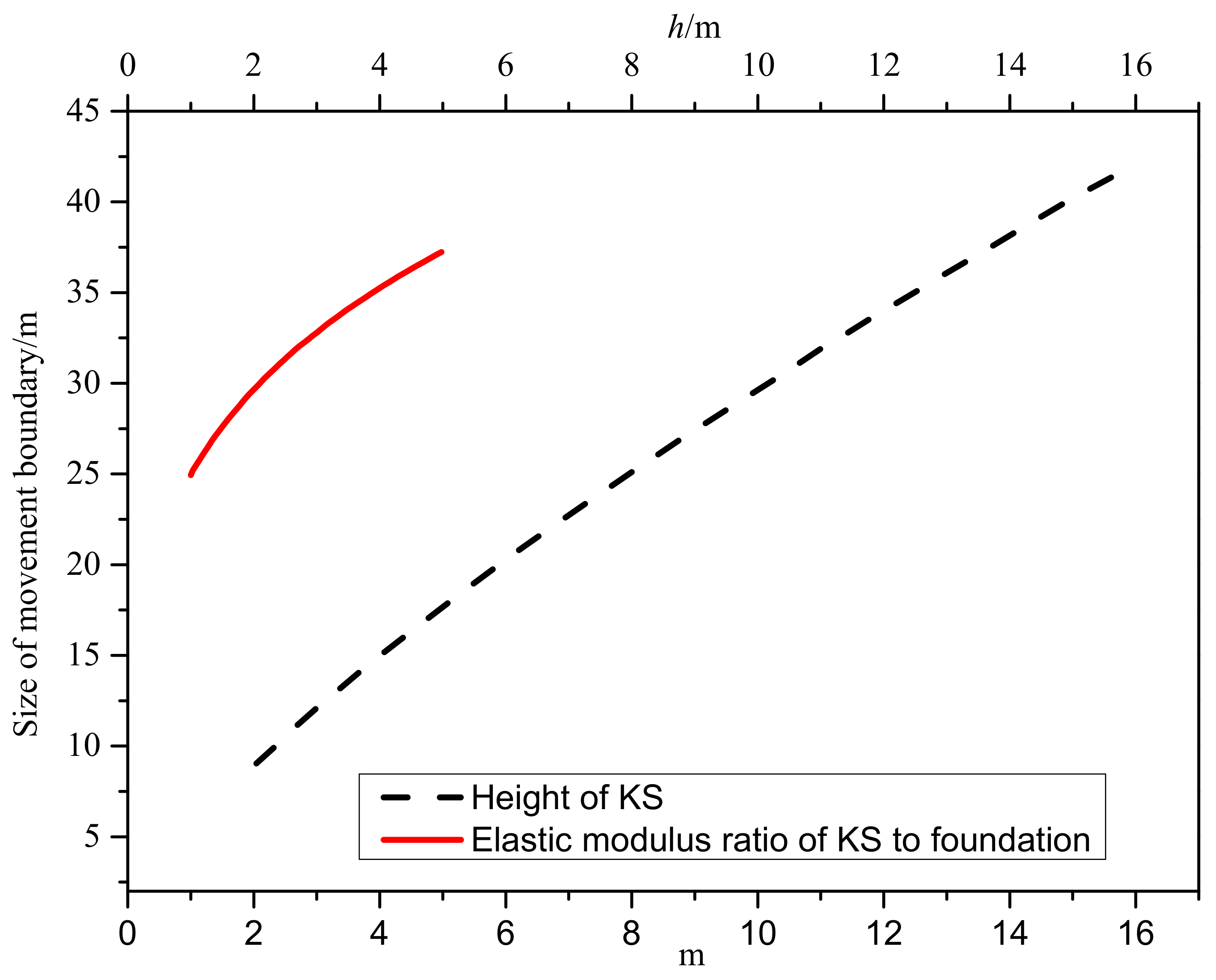
The influence of KS on strata movement boundary can be compared through the movement of strata in the case of either KS or soft rock in the same layer, respectively. Based on Equation (9), strata movement boundary is related to the elastic modulus E, height h, initial phase φ of the calculated strata, the height H from it to the coal seam floor, as well as the elastic modulus of foundation Ef. The ratio of elastic modulus of KS to that of foundation is set to be m. As can be found in Figure 5, the larger the values of m and h, the greater the size of movement boundary. In other words, the KS will expand the scope of strata movement.
For strata with same geological conditions, yet different lithology at the same layer, the initial phase remains unchanged while the elastic modulus and the height of KS increase, thus contributing to the expansion of movement compared with soft rock. The distance from KS movement boundary to the mining boundary rises with the increase of elastic modulus and height of KS. According to KS theory, the elastic modulus and the height of KS are greater than that of other strata. Therefore, the size of movement boundary of strata expands when there is typical KS in the overburden. The enlargement of subsidence area of KS inevitably leads to the increase of that of surface because the movement characteristics of strata above KS are determined by their physical and mechanical properties. This is consistent with the statistical data of observation of surface subsidence in numerous mines in the literature [18], offering a theoretical explanation for the expansion of surface subsidence when the overburden contains hard and stiff strata.
The gradient of angle of draw is defined as the ratio of the difference between the angles of draw of two adjacent layers to the vertical distance between them. When the points C and O in Figure 3 coincide, the corresponding gradient of angle of draw is zero for straight movement boundary, so is the difference between angles of draw of two adjacent layers. From Equations (11) and (12), a smaller height of strata and difference between elastic modulus of two adjacent layers is conducive to eliminating the difference between angles of draw of them. In other words, strata movement boundary can be approximate to a straight line when the lithology is homogeneous and the height of different strata are small in the overburden (that is, there is no typical KS in it).
Although mining factors such as mining height and mining width have an impact on strata movement boundary, their influence is closely related to the overburden geological conditions. Surface subsidence scope can be little with small mining width in spite of large mining height, demonstrating that mining factors are inseparable from geological factors. Hence, the effect of mining factors on strata movement boundary is not studied in this paper.
3. Movement Boundary Shape and Empirical Model
It is of practical significance to determine the movement boundary equation of rock strata for protecting surface structures, arranging underground roadway and designing staggered distance between the mining face of the upper and lower coal seam. As the concept of green mining gets well accepted, the requirements for ground structures protection become higher, so greater importance is attached to the prediction of surface subsidence. Nevertheless, in many cases, the protection of ground buildings only requires the determination of surface movement boundary, rather than the prediction of the movement and deformation value of the ground affected by coal mining. The movement and deformation of bedrock should be aware before underground water protection and structures construction. The prediction of strata movement and deformation demands the position of strata movement boundary, whatever method is adopted. Owing to various characteristics of the overburden, strata movement boundaries are also distinguishable in different mining areas.
According to the movement boundary shapes of bedrock and unconsolidated stratum, it is assumed that the distance from the movement boundary of the two to the mining boundary and the vertical distance to the coal seam satisfy the power function relationship. The mining boundary is defined as coordinate origin to establish the coordinate system, as shown in Figure 6. The movement boundary equations of bedrock and unconsolidated stratum are Equations (19) and (20), respectively:
where , , and are coefficients, and with are greater than 1. is the main influence radius of surface; is that of the interface of bedrock top; and is that of coal seam. is the bedrock height. The whole overburden strata can be expressed by Equation (20) when unconsolidated stratum is thin or the movement boundaries of bedrock and unconsolidated stratum are continuously smooth. The exact value of unknown parameters can be derived according to back analysis of measured data, and their approximate value can be calculated based on simulation results or Equation (9).
The physical significance of parameters in Equations (19) and (20) is shown in Figure 7 where r0 = 0. As can be seen from Figure 7a, with the increase of n, the movement boundary becomes steeper and steeper, and the area of subsidence shrinks. From Figure 7b, the larger the value of B, the smoother the movement boundary, and the larger the area of subsidence.
4. Model Verification
4.1. Physical Simulation
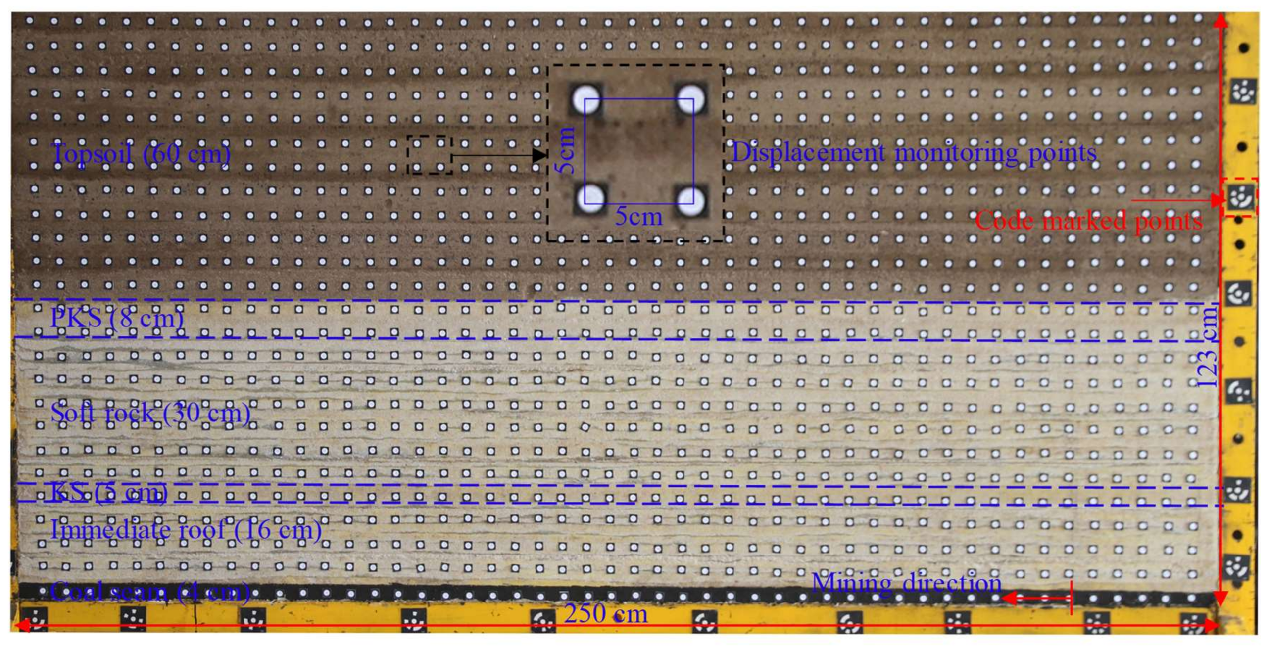
In order to verify the shape of the overburden movement boundary, the following experimental scheme was designed with physical and mechanical parameters of bedrock and unconsolidated stratum conforming to practical situation. The model in the physical simulation was 250 cm in length, 20 cm in width and 123 cm in height. According to similar material proportioning test of unconsolidated stratum, the geometric similarity ratio was 100:1 with density similarity ratio of 1.67:1 and stress similarity ratio of 167:1 in the simulation. In this experiment, river sand was taken as the basic aggregate, while gypsum, calcium carbonate and mica powder as auxiliary materials. The physical and mechanical parameters of each stratum in the model were determined on the basis of the similarity theory, as listed in Table 1. In the model, 25 horizontal displacement measurement lines were arranged, of which one is in the coal seam, 12 in bedrock and unconsolidated strata respectively. There are 49 displacement measurement points on each line with the horizontal and vertical distance of 5 cm between two adjacent points. A total of 1225 displacement measurement points were arranged, as exhibited in Figure 8. In the process of coal stoping, DigiMetric 3d (Beijing TenYoun 3D Technology Co., Ltd., Beijing, China) photogrammetry system was adopted to monitor displacement with theoretical measurement accuracy 0.1 mm/4 m.
On the right side of the model, a 30-cm-wide protective coal pillar for boundary was reserved. The mining was carried out from right to left with single excavation space of 5 cm Displacement measurement and data processing were conducted every 10 cm of stoping. Further excavation proceeded when all points cease to move.
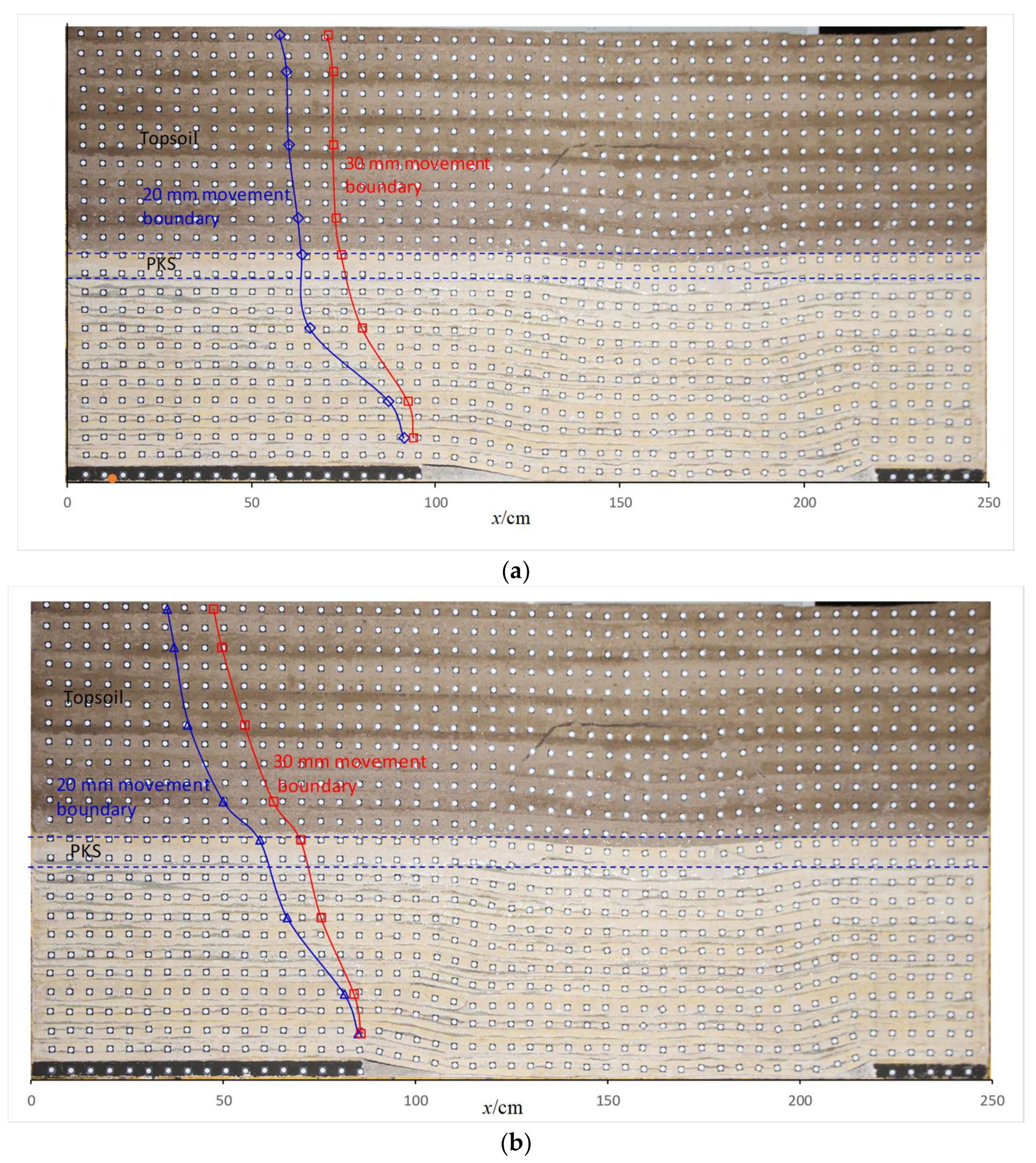
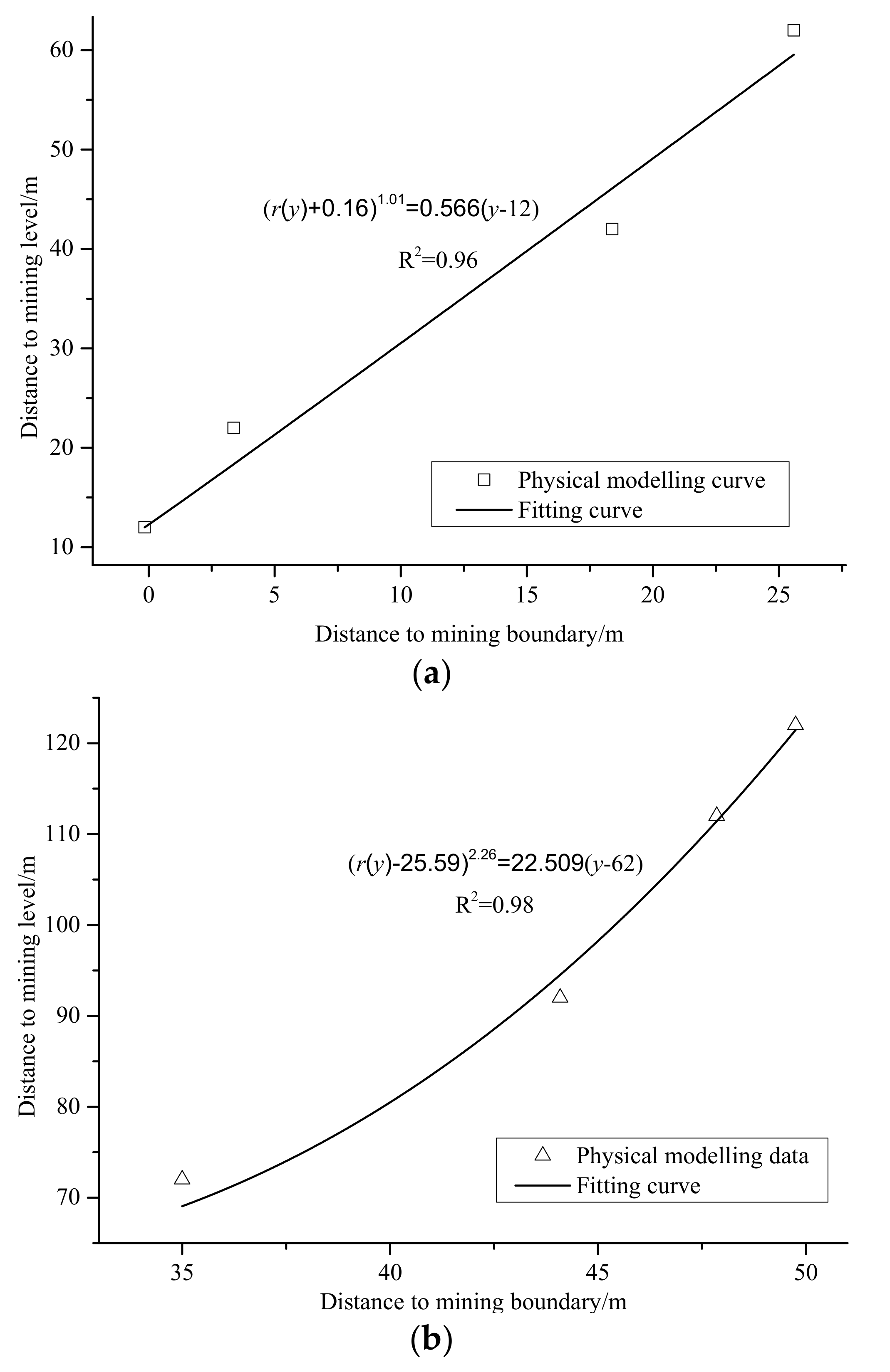
Figure 9 shows strata movement boundary with mining width of 125 m and 135 m, respectively. The blue and red curves represent the 20 mm and 30 mm strata movement boundary, respectively (The subsidence value has been converted according to the similarity ratio.). It is evident that the movement boundary shapes of bedrock and unconsolidated stratum are concave-upward curves, no matter which subsidence isoline is regarded as the movement boundary. The shapes of two subsidence isolines are consistent in the same figure. To illustrate whether Equation (16) can be considered as the equation of strata movement boundary, the movement boundaries of 20 mm bedrock and unconsolidated stratum are fitted, respectively. The result of bedrock (a correlation coefficient of 0.96) is shown in Figure 10a, while that of unconsolidated stratum (a correlation coefficient of 0.98) is in Figure 10b. As can be observed from Figure 9, the strata movement boundary is different in bedrock and unconsolidated stratum.
In Figure 9a, the change of movement boundary of unconsolidated stratum with layers is not as distinct as that of bedrock due to the arch structure in it. In Figure 9b, the arch structure has been destroyed and the movement of unconsolidated stratum approximately conforms to probability integral principle. The strata movement boundary turns into concave and convex shape at PKS where bedrock and unconsolidated stratum obey different movement and deformation laws. Therefore, there are differences in the movement boundary equations of the two (Figure 10a,b).
4.2. Numerical Simulation
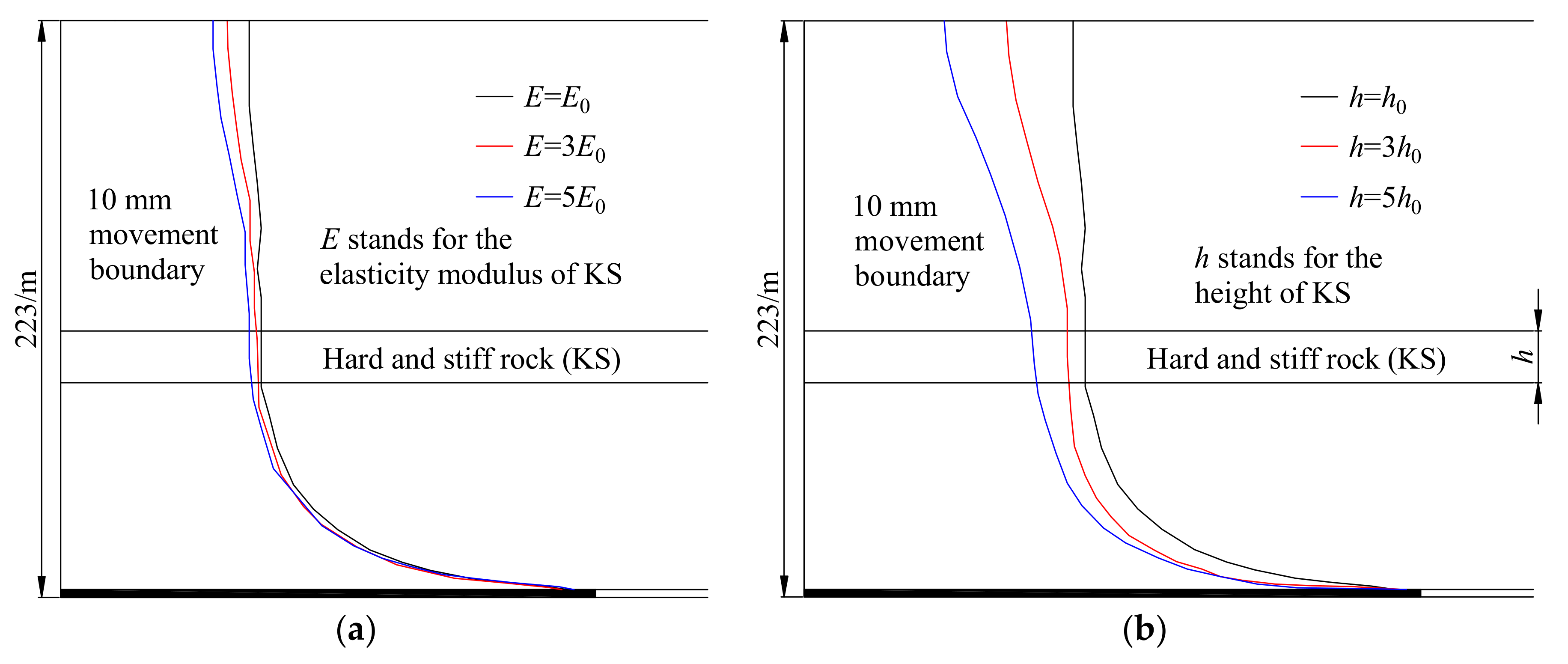
The finite-difference software FLAC3D (5.0 64-bit, Itasca Consulting China, Ltd., Wuhan, China) was introduced in this section to simulate the movement boundary of bedrock for further analysis of strata movement boundary shape and the influence of KS on strata movement boundary. Six models were designed in two groups. Models 1–3 in Group 1 were used to study the effect of elastic modulus of KS on the boundary. Among them, Model 1 was a basic model with parameters shown in Table 2; Models 2 and 3 were the same with Model 1 in size, but their elastic moduli of KS were 3 and 5 times that of Model 1, respectively. Models 4–6 in Group 2 were adopted to research the effect of KS height on the boundary. Among them, Model 4 was a basic model with parameters shown in Table 2; Models 5 and 6 were the same with Model 1 in size, but their KS heights were 3 and 5 times that of Model 4, respectively. The calculated model was 1000 m long, 4 m wide and 233 m high, and the coal seam was 3 m in horizontal height. Mohr-Coulomb criterion was adopted for constitutive relationship of the model. At the bottom of the model, the vertical displacement was fixed, and the horizontal displacement was restricted by boundaries in four directions with the upper boundary a free surface. The model was divided into five strata from the bottom up, namely coal floor, coal seam, immediate roof, KS and soft rock. The physical and mechanical parameters of each stratum in basic model are given in Table 2. After the completion of model, balancing calculation was performed under the effect of gravity, and then the monitoring variables were cleared. The working face was mined for 300 m in width at one time to obtain balanced default.
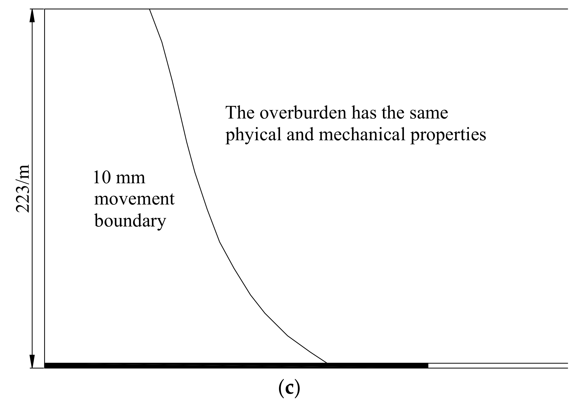
Regulations of coal pillar design and extraction for buildings, water bodies, railways, main shafts and roadways (hereafter referred to the Regulations) specify that the point with subsidence value of 10 mm is the boundary point [2]. Hence, all these points are linked to form the movement boundary of overburden strata. The subsidence isolines formed by these points in six groups are shown in Figure 11a,b and only a part of strata in the length direction is drawn for the need of demonstration. It can be seen from Figure 11a,b that regardless of the elastic modulus and height of KS in the overburden, the movement boundary is a concave-upward curve. In addition, the shape of strata movement boundary remains unchanged while the movement scope increases when elastic modulus and height of KS become larger. Figure 11c exhibits the strata movement boundary for the overburden with same physical and mechanical parameters (no KS). As can be observed in Figure 11c, the boundary is a concave-upward curve, but it is more like a straight line compared with that of the overburden with KS. The numerical simulation results of the influence of KS on strata movement boundary are consistent with the theoretical analysis in Section 3. In fact, there is little difference between the elastic modulus and height of KS compared with that of other strata in practices, so the n of bedrock movement boundary can take a small value in general geological condition.
5. Model Application in Protective Coal Pillars
5.1. Design of Protective Coal Pillars
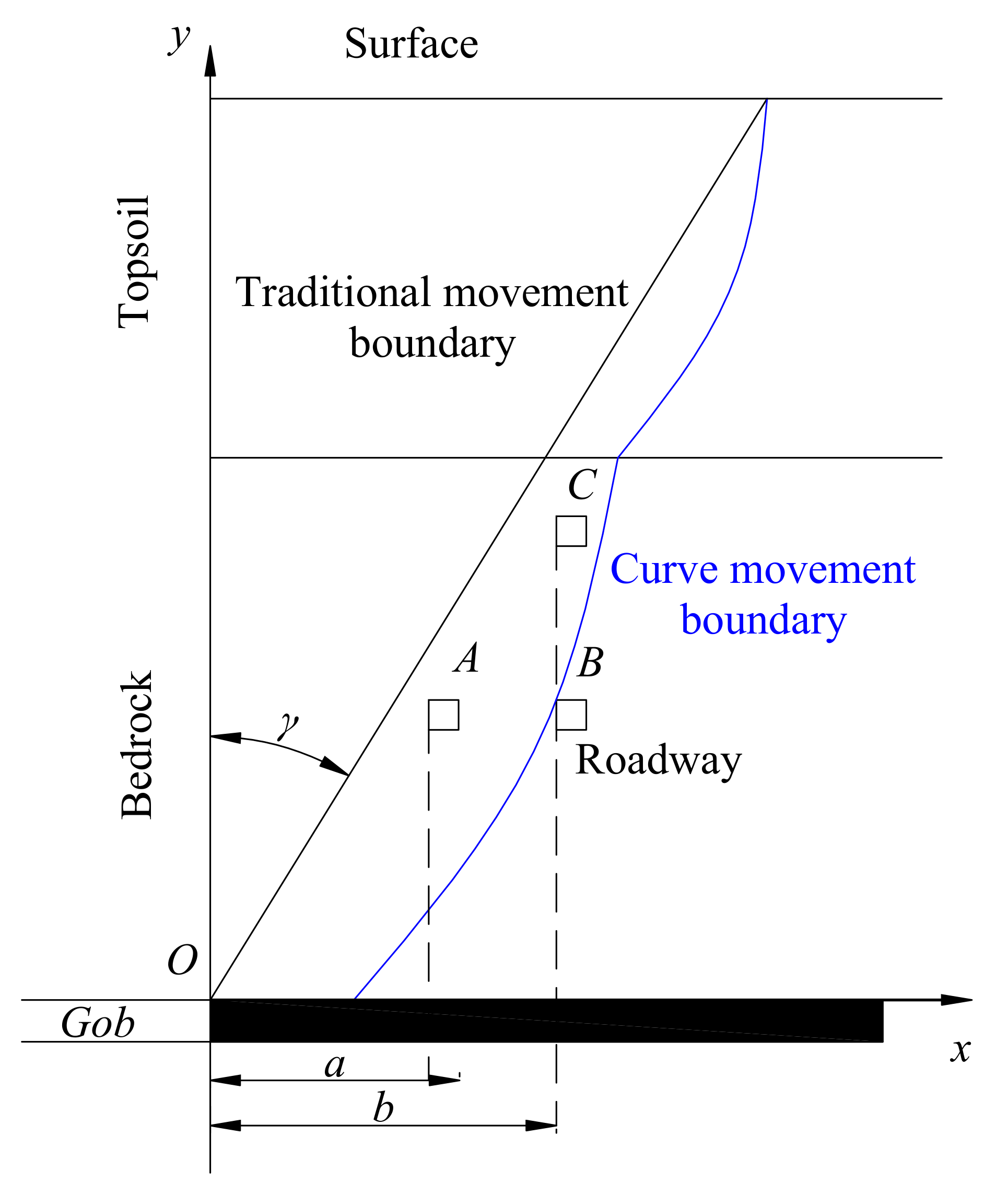
Strata movement boundary is the line to judge whether the overburden is affected by coal stoping. Inside of it, the displacement of the overburden changes under the impact of stoping, whereas outside of it, the overburden remains basically intact. As illustrated in Figure 12, the movement boundaries of bedrock and unconsolidated strata extend in a concave way from the coal seam to surface. The higher the coal seam, the larger the horizontal distance between movement boundary and mining boundary, yet the smaller the increasing trend of the distance. Therefore, the width of protective coal pillars should be designed according to strata movement boundary shape and the position of protectors to ensure that the roof roadway or underground structures are not affected by stoping. Specific procedures are as follows: calculating and drawing movement boundary based on actual situation after stoping; determining the intersection of the level of protected objects and strata movement boundary, then making its projection point on the coal seam; the distance between mining face boundary and projection point is the width of the protective coal pillar.
The overburden movement boundary after stoping is demonstrated in Figure 12. γ is both the included angle between traditional movement boundary and the vertical line and the angle between the line that links the intersection of curve movement boundary and surface with mining boundary and the vertical line. □ represents the roadway. After stoping, the roadway is located at A according to traditional method, and the width of the protective coal pillar should be a; the location of roadway is B based on curve movement boundary. It can be known from Figure 10 that a < b, and the roadway A is within the impact range of mining. Therefore, design requirements cannot be satisfied because the roadway is still affected by stoping and produces deformation when the pillar for roof roadway are designed based on traditional movement boundary. However, the pillars designed according to curve movement boundary can exclude roadway and underground structures from impact range of mining, thus better meeting engineering practice. In addition, the level of protected objects should also be taken into consideration in the design of the width of the pillar. In Figure 12, at different height, the roadway C is affected by mining while the roadway B is intact despite of the same width of pillars. Therefore, both the shape of strata movement boundary and the position of protected objects are important factors that should be considered in designing protective coal pillars.
As for the design of protective coal pillars in practices, it should be noted that different buildings and structures can resist varied hazards. And the basic factor in assessing the danger to surface construction objects or to linear objects is the horizontal specific deformation [49]. Consequently, the size of protective coal pillars can be optimized by the criterion of horizontal deformation, which can be divided into two groups. Criterion for the minimization of the resources trapped in the pillar is on the one hand and the criteria for facility protection (excavation) is on the other hand. Criteria for the protection of objects affect the size of the pillar in the direction of their growth, while the criterion of resource minimization acts in the opposite direction. Both criteria taken together optimize the size of the pillar in individual decks. It should be noted, however, that the designation of protective coal pillars, including optimization, is justified when geological and mining conditions as well as known parameters of rock mass theory are recognized.
5.2. Mining Conditions
The DingWu-3 passenger roadway of No.1 mine of Pingdingshan Tianan Coal Co., Ltd., Pingdingshan, China (hereafter referred to as passenger roadway) is 440 m in depth with loess of some 5.1 m. With a section of 4.2 m wide and 3 m high, the roadway is supported by the combination of bolt and anchor. The bolt is 20 mm in diameter and 2.2 m in length with raw and line space of 700 mm × 700 mm. The anchor is 20 mm in diameter and 7 m in length. Wu-10 coal seam contains Panels Wu10-21210 and Wu10-31010. Plan and cross-sectional views of passenger roadway and panels are shown in Figure 13.
As shown in Figure 13a, 1#~20# is the number of measurement points arranged in the passenger roadway. I~V on Wu10-31010 is the stoping position from January to May 2012, respectively, and the face mining is finished on 2 July 2012. VIII~XII on Wu-10-21210 is that from August to December 2011, respectively, and it is finished in January 2012. The passenger roadway is adjacent to DingWu-3 Eastern entry (hereafter referred to as Eastern entry) and DingWu-3 main return airway (hereafter referred to as return airway). Figure 13b shows that there is a 256-m-long protective coal pillar between Panels 21210 and 31010. To protect the passenger roadway, the pillar on the return roadway side of Panel 31010 is 90 m wide, and that on the railway roadway side of Panel 21210 is 165 m wide to protect the Eastern entry. The vertical distance between passenger roadway and Wu 10 coal seam is 85 m.
5.3. Field Measurement and Theoretical Analysis
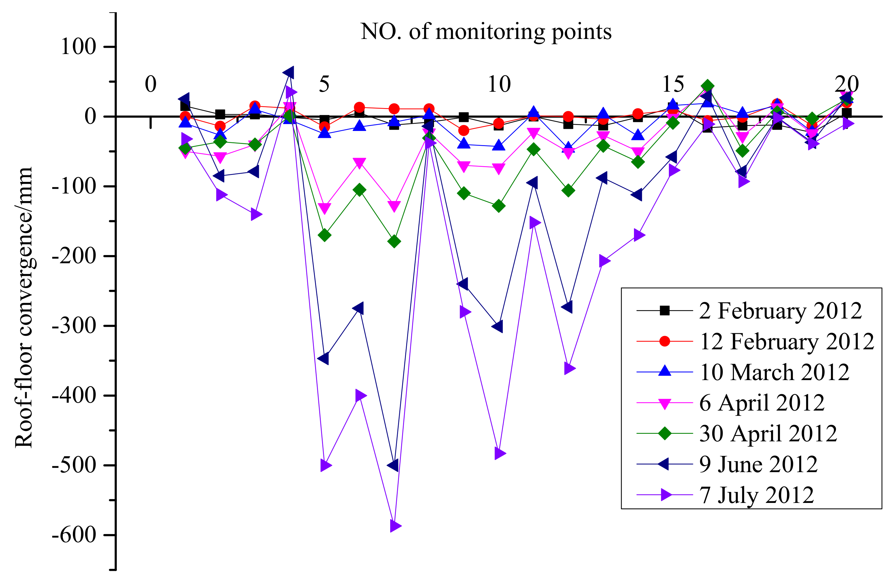
In order to observe the deformation characteristics of passenger roadway under the impact of mining, a total of 20 monitoring points (spacing: 50 m) are arranged in it, as presented in Figure 13. In the later observation, the data of roof-floor are measured by the cross-distributing point method and its initial data are obtained on 21 January 2012.
Field measurement has been carried out on 12 February, 10 March, 6 April, 30 April, 7 July and 9 June 2012, respectively. The results of roof-floor subsidence are shown in Figure 14. After the mining of Panel 21210 stops, there is no convergence of roof-floor before the stoping of Panel 31010, showing that the mining of Panel 21210 has almost no effect on the roadway. During the coal mining of Panel 31010 until July 2012, deformation of passenger roadway occurs, so it is caused by mining of Panel 31010.
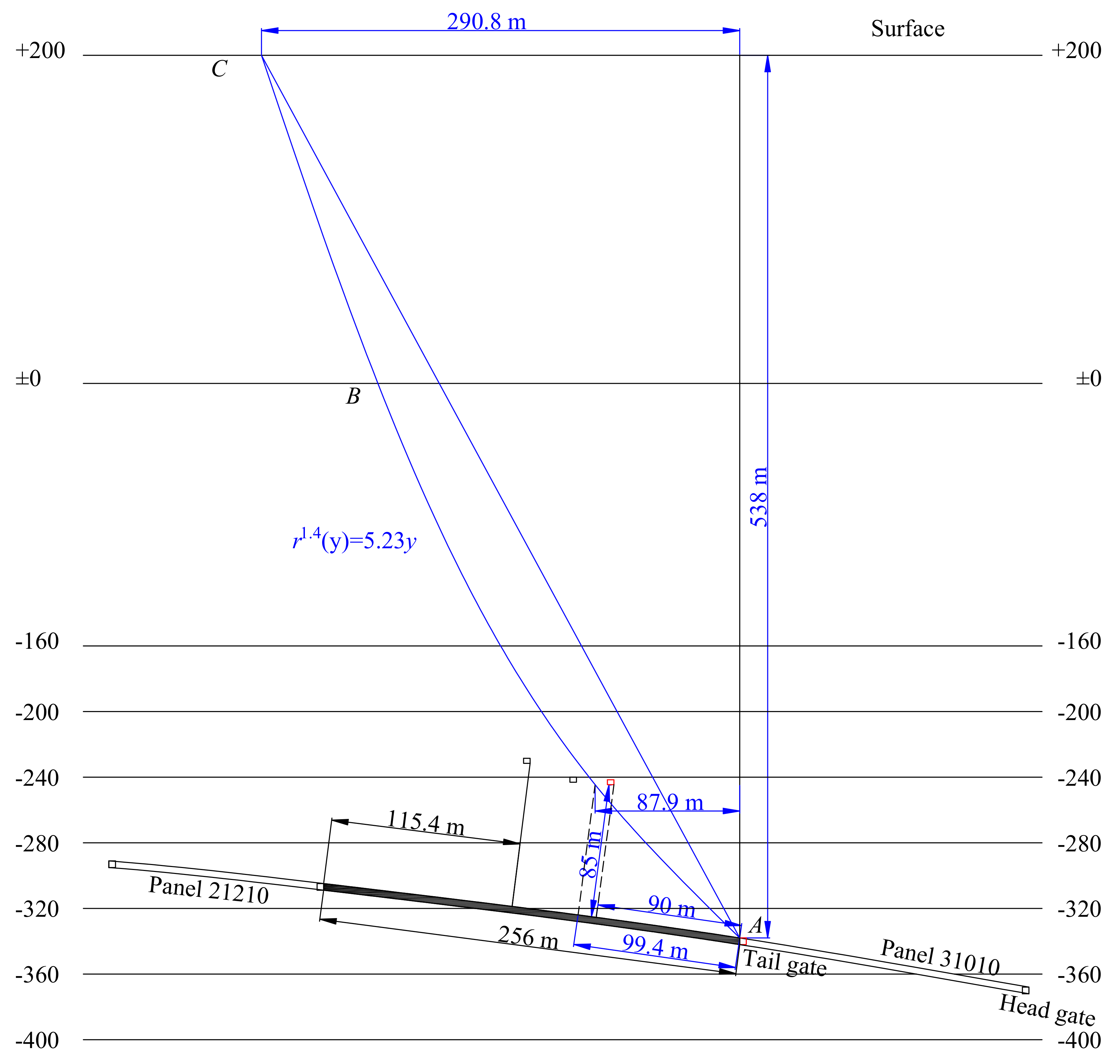
It is obvious in Figure 15 that the passenger roadway is beyond the influence range of mining if it is designed according to traditional movement boundary of AC, that is, the 90-m-wide pillar designed based on AC can protect the passenger roadway from deformation. However, measured results show that there is great convergence of passenger roadway. The width of the protective coal pillar for passenger roadway should be 99.4 m which is greater than the former width of 90 m, according to the curve boundary movement proposed in this paper. To avoid deformation of the passenger roadway, the width of the pillar should be at least 99.4 m. The reason for the deformation of passenger roadway is that the traditional movement boundary is not the real strata movement boundary.
The calculation procedure with equation of curve movement boundary is given below. For lack of the observation data of surface subsidence after coal mining of Panels 21210 and 31010, the surface boundary angle approximately equals to main influence angle whose tangent is calculated according to average of 11 mining faces near the coal area based on the Regulations. The average is 1.85. The buried depth of the return airway of Panel 31010 is 538 m, so the surface impact scope of Panel 31010 is 290.8 m according to the relationship between the tangent of main influence angle and buried depth after stoping. Due to a thin unconsolidated stratum of the overburden on Panel 31010, the strata movement boundary can be indicated by a curve. In order to make a better comparison, r0 in Equation (19) is set to zero because an endpoint of traditional movement boundary is on the mining boundary. To determine the two parameters n and B in the equation of a strata movement boundary, at least two points on the boundary are required, while only one point of C is fixed based on existing data. When n is 1.2, the movement boundary tends to be a straight line. However, the movement boundary cannot be approximated to straight owing to different lithology of each stratum in the overburden of Panel 31010 with a large depth. For better explanation of the problem, n is set to 1.4 in this paper. Put n = 1.4, r0 = 0 and r = 290.8 into Equation (19), obtaining B = 5.23, thus the equation of movement boundary of Panel 31010 is determined, as shown in Figure 15.
6. Conclusions
Mining activities is inevitable in many countries. Therefore, the prediction of strata and surface movement caused by mining practices is quite important to social constructions and roadways setting. In most situations, however, only the delimitation of the risk of collapse is required. For this reason, the overburden movement boundary shape and its influencing factors was studied in this paper. The research works indicated that the movement boundary was not a traditionally regarded straight line. Based on this, an empirical model was presented to guide the design of protective pillars.
(1) Strata movement boundary is divided into two parts, namely bedrock and unconsolidated stratum. The movement boundaries of the two are both concave-upward curves. The horizontal projection distance from the movement boundaries to the mining boundary and the vertical distance to the coal seam satisfy the power function relationship, but parameters of the two movement boundaries are different. Due to the difference of sedimentary time, physical and mechanical properties of bedrock and unconsolidated stratum are quite different. The latter is similar to granules, while the former is similar to the continuum, so the same mechanical model cannot be applied to movement boundaries of the two. The movement boundary of bedrock can be analyzed with continuum mechanics, while that of unconsolidated stratum can be studied by the influence function method.
(2) KS is an important geological factor affecting the size of strata movement boundary. With typical KS in the overburden, the surface subsidence area increases with the expansion of KS subsidence range. When the lithology of the overburden is relatively uniform and the strata is thin, strata movement boundary can be approximated as a straight line.
(3) Based on strata movement boundary, the width of the protective coal pillar on Panel 31010 in Pingdingshan No.1 mine is at least 99.4 m. The traditional movement boundary is not the real strata movement boundary, and the width of the pillar designed according to it is smaller than actually needed width, which is the reason for the convergence of passenger roadway.
The proposed model can be applicable to stratified overburden or soil in underground mining, whether in coal mining or tunnel excavation. Regarding the strata inclination, however, only horizontal layering is considered in the current modeling. If the overburden strata are inclined, the movement boundary would be different from that in a horizontal overburden. Nevertheless, if the proposed model is extended to the nearly-horizontal strata (with the angle of <8°), it may still be applicable within the tolerable error accepted by practical engineering.
Acknowledgments
This work was supported by the Fundamental Research Funds for the Central Universities (No. 2015XKMS093) and a Project Funded by the Priority Academic Program Development of Jiangsu Higher Education Institutions (No. SZBF2011-6-B35).
Author Contributions
Changchun He wrote the manuscript, designed and performed the experiments; Jialin Xu contributed the main ideas for the experiments, discussed the experimental results; Fei Wang discussed the experimental results and edited the manuscript; Feng Wang helped with technical support during the experiments, and provided materials and instruments to perform the theoretical analysis.
Conflicts of Interest
The authors declare no conflict of interest.
References
- Tiwary, R.K. Environmental impact of coal mining on water regime and its management. Water Air Soil Pollut. 2001, 132, 185–199. [Google Scholar] [CrossRef]
- Palchik, V. Formation of fractured zones in overburden due to longwall mining. Environ. Geol. 2003, 44, 28–38. [Google Scholar]
- Wright, I.A.; McCarthy, B.; Belmer, N.; Price, P. Subsidence from an underground coal mine and mine wastewater discharge causing water pollution and degradation of aquatic ecosystems. Water Air Soil Pollut. 2015, 226, 348–362. [Google Scholar] [CrossRef]
- Kratzsch, H. Mining Subsidence Engineering; Springer: Heidelberg, Germany, 1983; pp. 135–137. [Google Scholar]
- State Bureau of Coal Industry. Regulations of Coal Pillar Design and Extraction for Buildings, Water Bodies, Railways, Main Shafts and Roadways; Coal Industry Press: Beijing, China, 2000; pp. 46–47.
- Shu, D.M.; Bhattacharyya, A.K. Relationship between sub-surface and surface subsidence—A theoretical model. Min. Sci. Technol. 1990, 11, 307–319. [Google Scholar] [CrossRef]
- Dai, H.Y.; Teng, Y.H.; Lv, T.H.; Hu, J.Y. Analysis and control measures for the mining of dark shaft in dahuangshan coal mine. Min. Surv. 1999, 7–10. Available online: http://kns.cnki.net/KCMS/detail/detail.aspx?dbcode=CJFQ&dbname=CJFD9899&filename=KSCL901.002&uid=WEEvREcwSlJHSldRa1FhdkJkVWI2K1hRUnFrSXBsdWRma1ZmR2k3WFBlRT0=$9A4hF_YAuvQ5obgVAqNKPCYcEjKensW4ggI8Fm4gTkoUKaID8j8gFw!!&v=MTcwMTE0T1g2VHJIMDNlYk9jUmJtZFpPZHFFaTNuVnc9PUxqN0lZcnE0SDgvTXI0MHFGNTRPZmdnNXpoQVU0amg=. (accessed on 7 August 2017).
- Wang, F.; Xu, J.L.; Xie, J.L.; Guo, J.K.; Liu, D.L. Method of designing protective coal pillar on roof roadway based onmining induced stress boundary line. J. China Coal Soc. 2013, 38, 1917–1922. [Google Scholar]
- Aksoy, C.O.; Kose, H.; Onargan, T.; Koca, Y.; Heasley, K. Estimation of limit angle using laminated displacement discontinuity analysis in the Soma coal field, Western Turkey. Int. J. Rock Mech. Min. Sci. 2004, 41, 547–556. [Google Scholar] [CrossRef]
- Yu, Y.M.; Dai, H.Y.; He, Z.J. Mining design for shaft and industry square pillar and practice in No.6 coal mine in Changguang mining district. J. Min. Saf. Eng. 2008, 25, 202–206. [Google Scholar]
- Zhou, Z.; Li, Q.F. Safety coal pillar design of coal mining under railway. Miner. Eng. Res. 2012, 27, 23–27. [Google Scholar]
- Hong, M. Mountain village protection coal pillar stay and mining impact deformation prediction. Coal Chem. Ind. 2014, 37, 1–4. [Google Scholar]
- Abdallah, M.; Verdel, T. Behavior of a masonry wall subjected to mining subsidence, as analyzed by experimental designs and response surfaces. Int. J. Rock Mech. Min. Sci. 2017, 100, 199–206. [Google Scholar] [CrossRef]
- Sepehri, M.; Apel, D.B.; Hall, R.A. Prediction of mining-induced surface subsidence and ground movements at a Canadian diamond mine using an elastoplastic finite element model. Int. J. Rock Mech. Min. Sci. 2017, 100, 73–82. [Google Scholar] [CrossRef]
- Yao, X.L.; Whittaker, B.N.; Reddish, D.J. Influence of overburden mass behavioural properties on subsidence limit characteristics. Min. Sci. Technol. 1991, 13, 167–173. [Google Scholar] [CrossRef]
- Ren, G.; Li, J. A study of angle of draw in mining subsidence using numerical modeling techniques. Electron. J. Geotech. Eng. 2008, 13, 1–14. [Google Scholar]
- Deng, K.Z.; Ma, W.M. Influence of thickness on the moving Angle and the radius of influence. Min. Surv. 1989. Available online: http://kns.cnki.net/KCMS/detail/detail.aspx?dbcode=CJFQ&dbname=CJFD8589&filename=KSCL198901011&uid=WEEvREcwSlJHSldRa1FhdkJkVWI2K1hRUnFrSXBsdWRma1ZmR2k3WFBlRT0=$9A4hF_YAuvQ5obgVAqNKPCYcEjKensW4ggI8Fm4gTkoUKaID8j8gFw!!&v=MDI3MTQ5RVpZUjhlWDFMdXhZUzdEaDFUM3FUcldNMUZyQ1VSTEtmWk9Sc0Z5emhVYi9CTGo3SVlyS3hGdGpNcm8=. (accessed on 7 August 2017).
- Hao, Y.J.; Chen, S.H. Influence rule on hard rock seams to rocks defermation. Coal 2000, 9, 8–9. [Google Scholar]
- Yu, B.H.; Zhu, W.B.; Xu, J.L. Numerical simulation of surface subsidence induced by deep mining. J. Min. Saf. Eng. 2007, 24, 422–426. [Google Scholar]
- Wang, G.Y. Understanding of the boundary of subsidence basin in the overburden. Min. Surv. 1994, 35–36. Available online: http://kns.cnki.net/KCMS/detail/detail.aspx?dbcode=CJFQ&dbname=CJFD9495&filename=KSCL401.010&uid=WEEvREcwSlJHSldRa1FhdkJkVWI2K1hRUnFrSXBsdWRma1ZmR2k3WFBlRT0=$9A4hF_YAuvQ5obgVAqNKPCYcEjKensW4ggI8Fm4gTkoUKaID8j8gFw!!&v=MTUzOTE0T1g2VHJIMDNlYk9jUmJtZFpPZHBGaXJnVUE9PUxqN0lZcmU0SDgvTXJvOHFGNTRPZmdnNXpoQVU0amg=. (accessed on 7 August 2017).
- Gao, Y.F.; Shen, G.H. Rock mass structure and relationship between properties and deformation of rock strata. Min. Surv. 1988, 1. Available online: http://kns.cnki.net/KCMS/detail/detail.aspx?dbcode=CJFQ&dbname=CJFD8589&filename=KSCL198801006&uid=WEEvREcwSlJHSldRa1FhdkJkVWI2K1hRUnFrSXBsdWRma1ZmR2k3WFBlRT0=$9A4hF_YAuvQ5obgVAqNKPCYcEjKensW4ggI8Fm4gTkoUKaID8j8gFw!!&v=MjIwODBMajdJWXJLeEZ0bk1ybzlGWW9SOGVYMUx1eFlTN0RoMVQzcVRyV00xRnJDVVJMS2ZaT1JzRnl6aFZidlA=. (accessed on 7 August 2017).
- Dai, H.Y.; Lian, X.G.; Liu, J.Y.; Liu, Y.X.; Zhou, Y.M.; Deng, W.N.; Cai, Y.F. Model study of deformation induced by fully mechanized caving below a thick loess layer. Int. J. Rock Mech. Min. Sci. 2010, 47, 1027–1033. [Google Scholar]
- Wu, K.; Cheng, G.L.; Zhou, D.W. Experimental research on dynamic movement in strata overlying coal mines using similar material modeling. Arab. J. Geosci. 2015, 8, 6521–6534. [Google Scholar] [CrossRef]
- Yu, X.Y.; Zhang, E.Q. Mining Damages, 2nd ed.; China Coal Industry Publishing House: Beijing, China, 2010; pp. 53–55. [Google Scholar]
- Prusek, S.; Jędrzejec, E. Adjustment of the Budryk-Knothe theory to forecasting deformations of gateroads. Arch. Min. Sci. 2008, 53, 97–114. [Google Scholar]
- Gruszczyński, S. Standards and Thresholds for Impact Assessment; Springer: Heidelberg, Germany, 2008; pp. 185–202. [Google Scholar]
- Strzałkowski, P. Mathematical Model of Forecasting the Formation of Sinkhole Using Salustowicz’s Theory. Arch. Min. Sci. 2015, 60, 63–71. [Google Scholar]
- Jenike, A.W. Gravity Flow of Bulk Solids; Bulletin No. 108; Utah State University: Logan, UT, USA, 1961. [Google Scholar]
- Giunta, J.S. Flow patterns of granular materials in flat-bottom bins. J. Eng. Ind. 1969, 91, 406–413. [Google Scholar] [CrossRef]
- Blair-Fish, P.M.; Bransby, P.L. Flow patterns and wall stresses in a mass-flow bunker. J. Eng. Ind. 1973, 95, 17–26. [Google Scholar] [CrossRef]
- Moreea, S.B.M.; Nedderman, R.M. Exact stress and velocity distributions in a cohesionless material discharging from a conical hopper. Chem. Eng. Sci. 1996, 51, 3931–3942. [Google Scholar] [CrossRef]
- Mullins, W.W. Stochastic Theory of Particle Flow under Gravity. J. Appl. Phys. 1972, 43, 665–678. [Google Scholar] [CrossRef]
- Mullins, W.W. Nonsteady-state particle flow under gravity—An extension of the stochastic theory. J. Appl. Mech. 1974, 41, 49–68. [Google Scholar] [CrossRef]
- Bak, P.; Tang, C.; Wiesenfeld, K. Self-organized criticality. Phys. Rev. A 1988, 38, 364–374. [Google Scholar] [CrossRef]
- Watson, G.R.; Rotter, J.M. A finite element kinematic analysis of planar granular solids flow. Chem. Eng. Sci. 1996, 51, 3967–3978. [Google Scholar] [CrossRef]
- Sielamowicz, I.; Kowalewski, T.A.; Błoński, S. Central and eccentric granular material flows in bins/hoppers registered by DPIV optical technique. Acta Agrophys. 2004, 4, 519–531. [Google Scholar]
- Sielamowicz, I. Experimental analysis of granular material flows using the technique of digital particle image velocimetry. Eng. Trans. 2005, 53, 197–229. [Google Scholar]
- Sielamowicz, I.; Blonski, S.; Kowalewski, T.A. Optical technique DPIV in measurements of granular material flows, Part 1 of 3—Plane hoppers. Chem. Eng. Sci. 2005, 60, 589–598. [Google Scholar] [CrossRef]
- Szczepiński, W. A comparative analysis of theoretical models of gravity movements of cohesionless granular media. Eng. Trans. 2007, 55, 181–192. [Google Scholar]
- Sielamowicz, I.; Czech, M.; Kowalewski, T.A. Empirical description of granular flow inside a model silo with vertical walls. Biosyst. Eng. 2011, 108, 334–344. [Google Scholar] [CrossRef]
- Wang, Y.; Lu, Y.; Ooi, J.Y. A numerical study of wall pressure and granular flow in a flat-bottomed silo. Powder Technol. 2015, 282, 43–54. [Google Scholar] [CrossRef]
- Nguyen, T.V.; Brennen, C.E.; Sabersky, R.H. Funnel flow in hoppers. J. Appl. Mech. 1980, 47, 729–735. [Google Scholar] [CrossRef]
- Litwiniszyn, J. Application of the equation of stochastic processes to mechanics of loose bodies. Arch. Mech. 1956, 8, 393–411. [Google Scholar]
- He, G.Q.; Yang, L.; Ling, G.D.; Jia, F.C.; Hong, D. Mining Subsidence Science; China University of Mining and Technology Press: Xuzhou, China, 1991; pp. 118–147. [Google Scholar]
- Department of mathematics, Tongji University. Advanced Mathematics, 5th ed.; Higher Education Press: Beijing, China, 2006; pp. 149–151. [Google Scholar]
- Qian, M.G.; Miao, X.X.; Xu, J.L. Theoretical study of key strata in ground control. J. China Coal Soc. 1996, 21, 225–230. [Google Scholar]
- Xu, J.L.; Qian, M.G. Study on the influence of key strata movement on subsidence. J. China Coal Soc. 2000, 25, 122–126. [Google Scholar]
- Xu, J.L.; Qian, M.G.; Zhu, W.B. Study on influence of primary key strata on surface dynamic subsidence. Chin. J. Rock Mech. Eng. 2005, 24, 787–791. [Google Scholar]
- Dzegniuk, B.; Hejmanowski, R.; Sroka, A. Evaluation of the Damage Hazard to Building Objects on the Mining Areas Considering the Deformation Course in Time. In Proceedings of the Xth International Congress of the International Society for Mine Surveying, Fremantle, Western Australia, 2–6 November 1997. [Google Scholar]
Figure 1.
Common type of overburden strata on the coal seam (the upper most KS is defined as PKS).
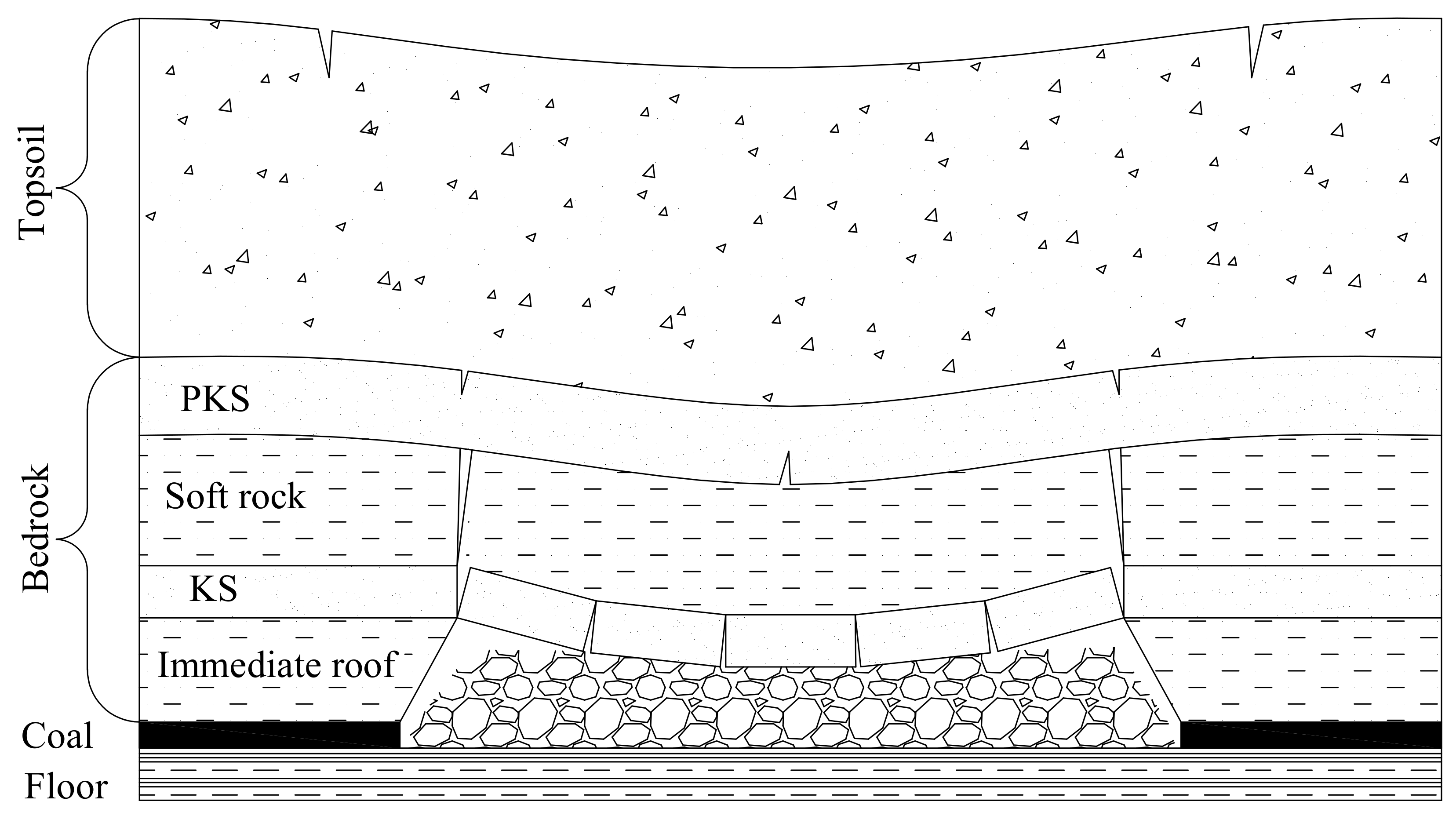
Figure 2.
Mechanical model of elastic foundation beam of the overburden subsidence.
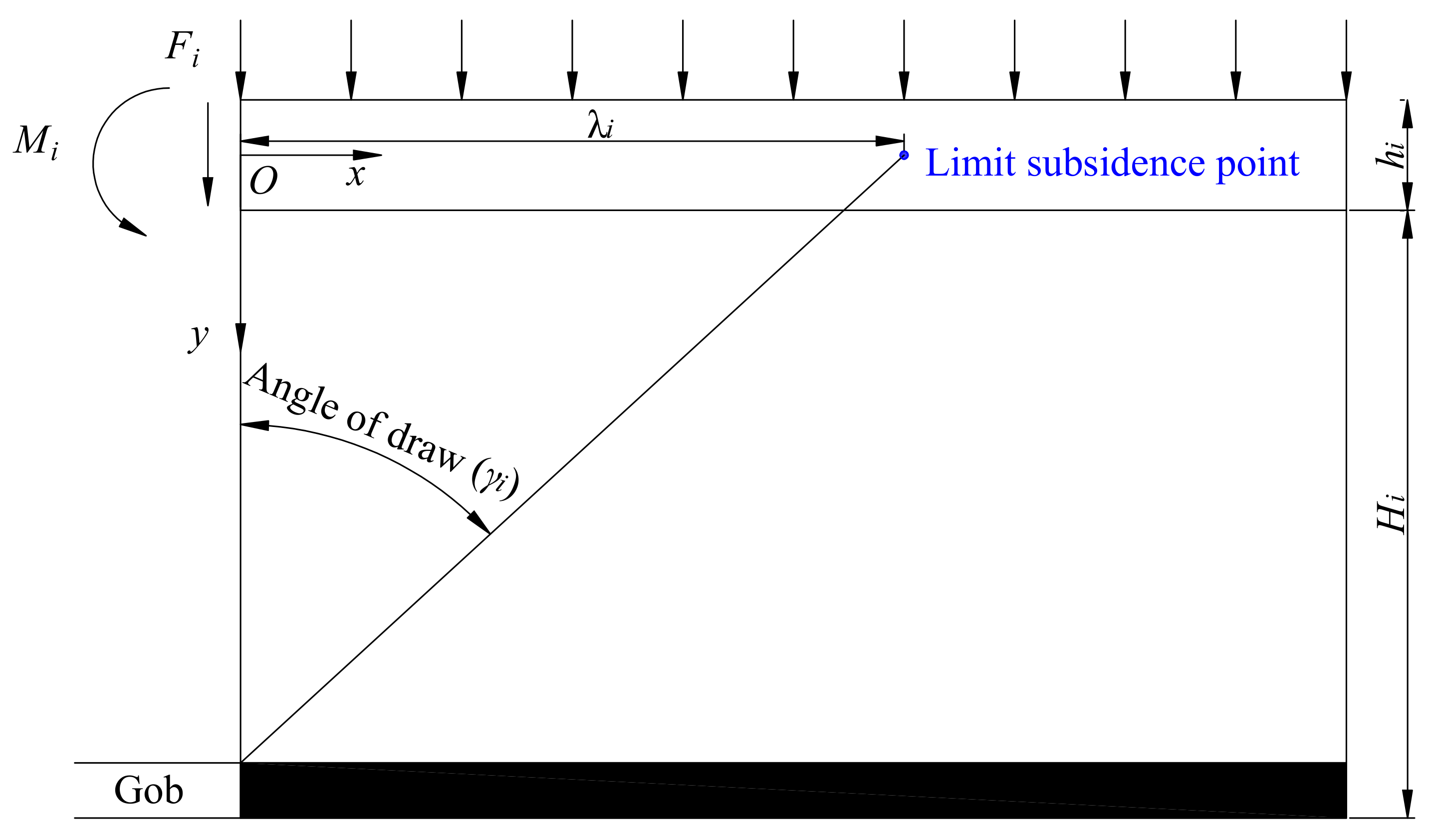
Figure 3.
The angle of draw in accordance with different strata movement boundary shapes.
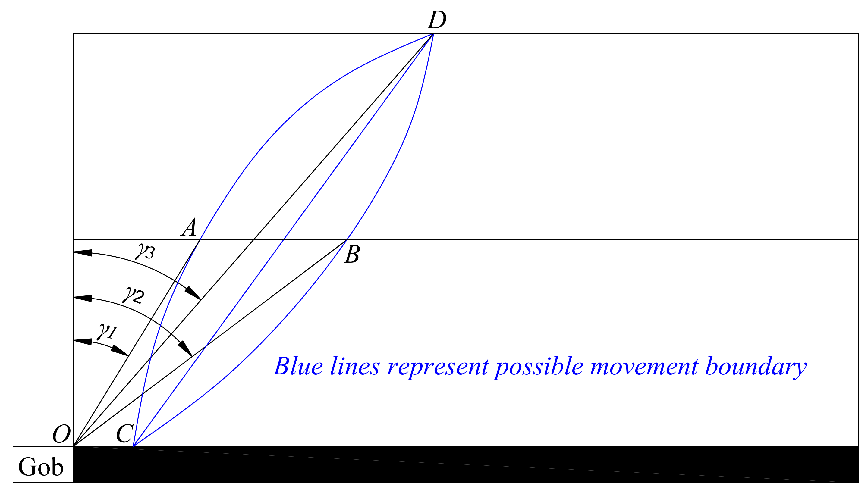
Figure 4.
Theoretical model of granular media movement in the SM theory.

Figure 5.
Relationship between the size of movement boundary and KS height and m.

Figure 6.
Movement boundary equations of bedrock and unconsolidated stratum.
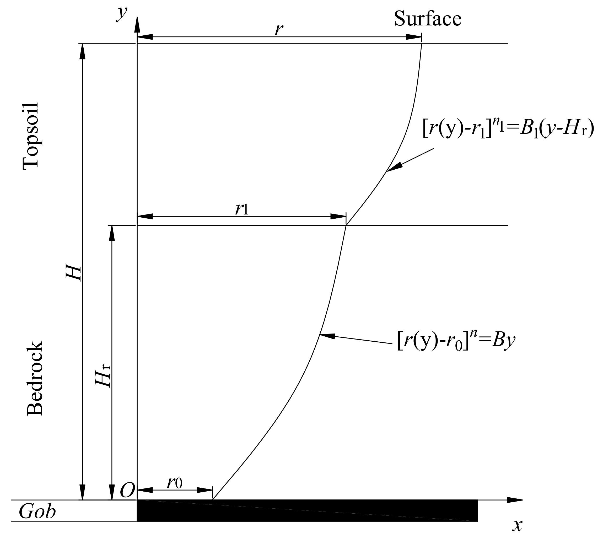
Figure 7.
The change laws of movement boundary with n and B (r0 = 0). (a) B = 2; (b) n = 2.
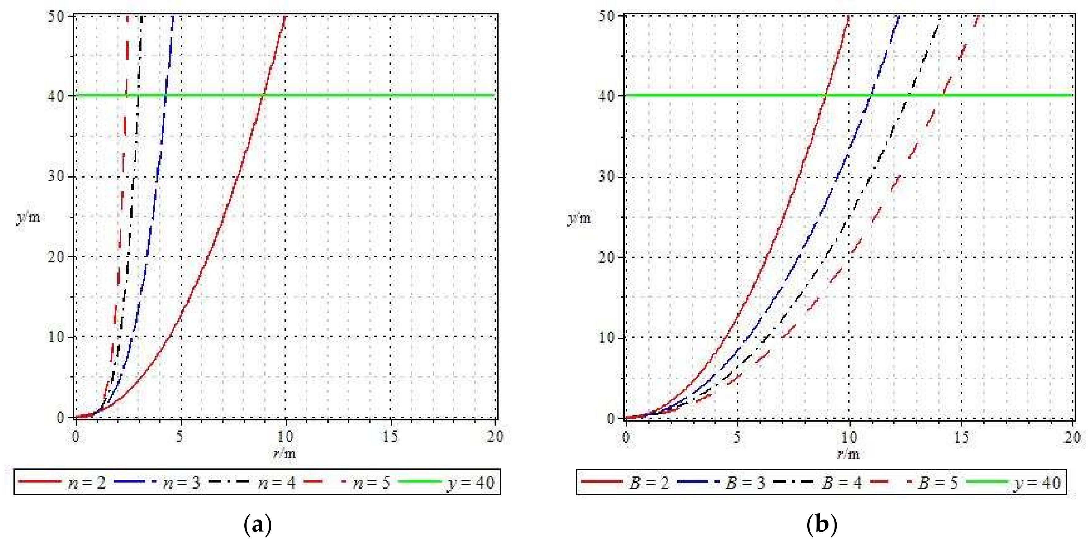
Figure 8.
The actual experiment equipment and the completed model.

Figure 9.
Strata movement boundary in physical simulation. (a) Strata movement boundary when working face proceeds to 125 cm; (b) Strata movement boundary when working face proceeds to 135 cm.
Figure 9.
Strata movement boundary in physical simulation. (a) Strata movement boundary when working face proceeds to 125 cm; (b) Strata movement boundary when working face proceeds to 135 cm.

Figure 10.
Movement boundary equation of bedrock and unconsolidated stratum in physical simulation. (a) Movement boundary in bedrock; (b) Movement boundary in unconsolidated stratum.
Figure 10.
Movement boundary equation of bedrock and unconsolidated stratum in physical simulation. (a) Movement boundary in bedrock; (b) Movement boundary in unconsolidated stratum.

Figure 11.
The 10 mm movement boundary of the overburden with and without KS. (a) The influence of elastic modulus of KS; (b) The influence of height of KS; (c) Movement boundary without KS in the overburden.
Figure 11.
The 10 mm movement boundary of the overburden with and without KS. (a) The influence of elastic modulus of KS; (b) The influence of height of KS; (c) Movement boundary without KS in the overburden.


Figure 12.
Design schematic diagram of roadway position and the width of protective coal pillar.5.2. Case study.
Figure 12.
Design schematic diagram of roadway position and the width of protective coal pillar.5.2. Case study.

Figure 13.
Relationship between location of roadway and panels. (a) Plan view of passenger roadway and panels; (b) A-A cross section.
Figure 13.
Relationship between location of roadway and panels. (a) Plan view of passenger roadway and panels; (b) A-A cross section.
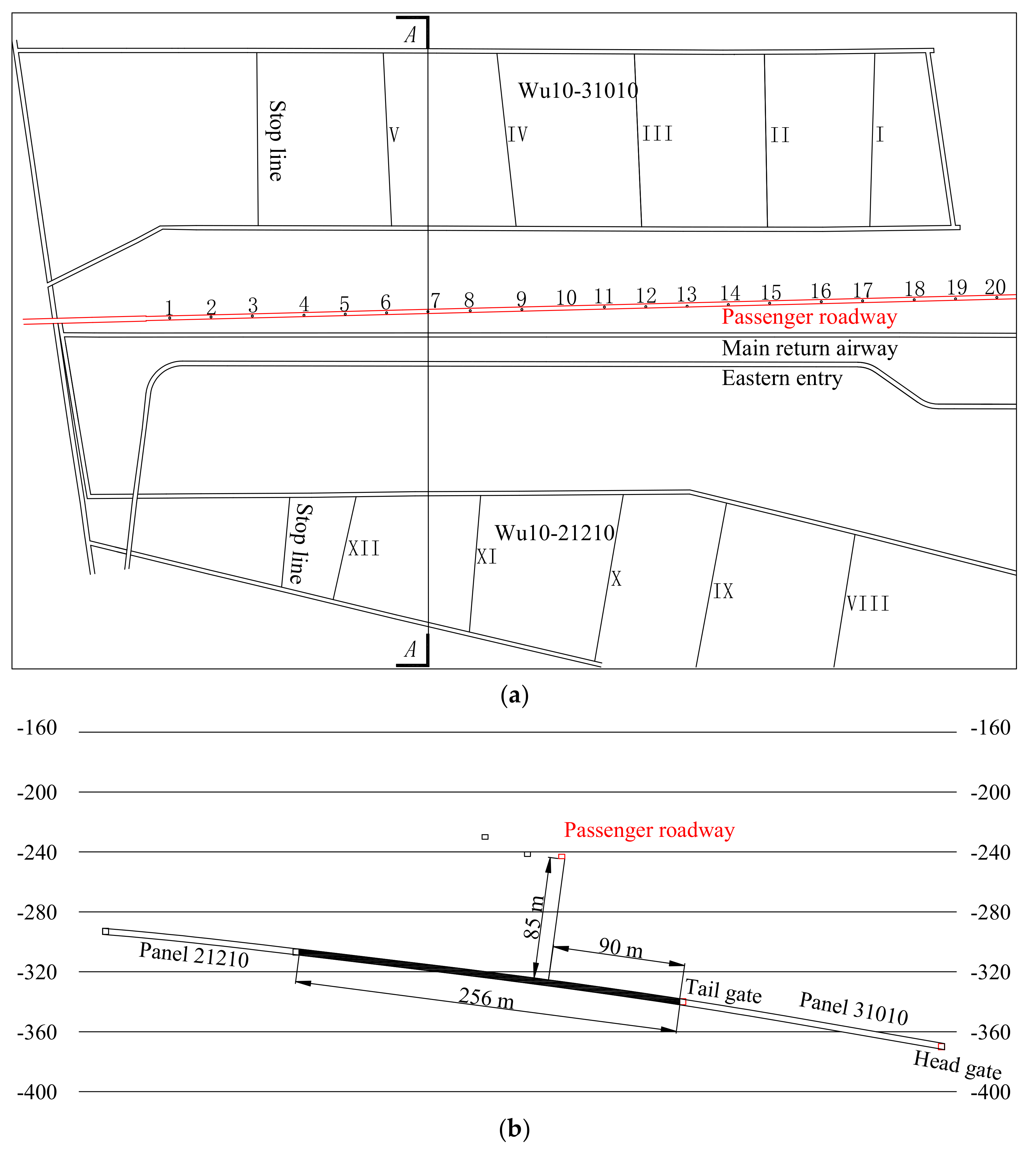
Figure 14.
Roof-floor convergence of passenger roadway.

Figure 15.
The width of the protective coal pillar for passenger roadway designed according to strata movement boundary.
Figure 15.
The width of the protective coal pillar for passenger roadway designed according to strata movement boundary.

Table 1.
Physical model size and material ratios.
| No. | Rock Strata | Height | Material Ratio | Bulk Density | Elasticity Modulus | Poisson’s Ratio |
|---|---|---|---|---|---|---|
| m | Sand:CaCO3:Gypsum | kN/m3 | GPa | |||
| 1 | Topsoil | 60 | 850.91 kg sand and 85.1 kg saw dust | 12.0 | 0.00093 | 0.35 |
| 2 | PKS | 8 | 50:3:7 | 16.8 | 0.013974 | 0.20 |
| 3 | Soft rock 2 | 30 | 50:7:3 | 16.8 | 0.04790 | 0.28 |
| 4 | KS | 5 | 60:5:5 | 16.8 | 0.09581 | 0.22 |
| 5 | Soft rock 1 | 16 | 50:7:3 | 16.8 | 0.04790 | 0.28 |
| 6 | Coal seam | 4 | 70:7:3 | 16.8 | 0.01796 | 0.28 |
Table 2.
Physical and mechanical parameters of basic model.
| No. | Strata | Density/(kg/m3) | Height/m | Bulk Modulus/GPa | Shear Modulus/GPa | Cohesion/MPa | Tensile Strength/MPa | Frictionangle/(°) |
|---|---|---|---|---|---|---|---|---|
| 1 | Coal floor | 2600 | 10 | 4.54 | 2.34 | 5 | 5 | 34 |
| 2 | Coal seam | 1600 | 3 | 1.52 | 0.78 | 1 | 1 | 23 |
| 3 | Immediate floor | 2500 | 80 | 2.00 | 1.20 | 2 | 2 | 33 |
| 4 | KS | 2600 | 20 | 6.67 | 4.00 | 4 | 5 | 40 |
| 5 | Soft rock | 2400 | 120 | 1.33 | 0.80 | 1 | 3 | 28 |
© 2018 by the authors. Licensee MDPI, Basel, Switzerland. This article is an open access article distributed under the terms and conditions of the Creative Commons Attribution (CC BY) license (http://creativecommons.org/licenses/by/4.0/).
Share and Cite
MDPI and ACS Style
He, C.; Xu, J.; Wang, F.; Wang, F. Movement Boundary Shape of Overburden Strata and Its Influencing Factors. Energies 2018, 11, 742. https://doi.org/10.3390/en11040742
AMA Style
He C, Xu J, Wang F, Wang F. Movement Boundary Shape of Overburden Strata and Its Influencing Factors. Energies. 2018; 11(4):742. https://doi.org/10.3390/en11040742
Chicago/Turabian StyleHe, Changchun, Jialin Xu, Fei Wang, and Feng Wang. 2018. "Movement Boundary Shape of Overburden Strata and Its Influencing Factors" Energies 11, no. 4: 742. https://doi.org/10.3390/en11040742
Note that from the first issue of 2016, this journal uses article numbers instead of page numbers. See further details here.