1. Introduction
In recent years, distributed generations, e.g., wind and solar power, have been developing rapidly. Comparing with traditional power generation forms, distributed generations are environment-friendly technologies, and they often form micro-grids via inverters, which is an important complementary of bulk power network. However, since there are so many distributed generations in the micro-grid system, power electronic inverters are also widely used. In addition, various kinds of nonlinear loads such as electric vehicles are increasingly integrated into the micro-grid, thus a power quality problem inside micro-grid occurs and increases problems of heating, incremental losses, voltage and current distortion, which threaten our daily life. It is not only the micro grid itself that can be broken down by such problems, but the voltage and frequency of the distributed power system can also be influenced through the point of common coupling (PCC) [
1,
2,
3]. Meanwhile, power management strategies play an increasingly important role in power quality regulation for micro-grids [
4,
5,
6].
As distributed generations are connected to the micro-grid via inverter, hence the control strategy of inverters influence system stability and power quality. Among all the inverter control strategies, droop control is considered as the best strategy at present, which can distribute the output power of inverters properly under the island mode of the micro-grid, even if there is no common communication line among distributed generations (DGs); meanwhile, the voltage and frequency can be controlled within related national standards by this strategy [
7,
8,
9]. However, there are some shortcomings in the traditional droop control strategy. Firstly, system reactive power cannot be distributed accurately while the equivalent impedance of micro sources is different [
10]. Secondly, system voltage and frequency will not maintain their stability under abrupt load variation [
11,
12]. In addition, the magnitude of harmonic power varies with the amount of non-linear loads integrated into the micro-grid. The existence of harmonic power will have an effect on system devices, including transformers, capacitors, and electric rotating machines. It is also shown that harmonic power will influence the voltage amplitude and waveform of PCC [
13], which may cause resonance and eventually lead to the loss of system stability.
At present, there are less researches on multi-inverter-based micro-grid power quality. Traditional methods for limiting waveforms distortion are to make direct compensation by installing passive or centralized active power filters, but the high cost of these kinds of devices should not be ignored, and these methods can only improve harmonic components, while, as to fundamental component power quality and accurate reactive power distribution, they neither make tense research nor give an integral solution [
14,
15,
16,
17]. Reference [
18] proposed a compensation method based on a unified power quality conditioner (UPQC) to improve the power quality index of PCC, but though this device is widely used in large capacity and high voltage power grids, it is difficult to generalize the use of this device in low voltage distributed grids and micro-grids. Many experts considered designing an inverter control strategy to improve accurate reactive power distribution and govern harmonic components [
19,
20,
21,
22,
23,
24,
25,
26,
27,
28]. Reference [
19] proposed a method to govern harmonic components in the micro-grid that combines the technology of active filter and inverter controller, so the utilization of inverter is obviously improved and the cost of active filter is effectively decreased; however, the design of that controller is too complex to popularize. The general method to distribute reactive power accurately is to add virtual impedances into inverters [
20,
21,
22]. By measuring the output voltage and current of inverters and adjusting their output impedances, i.e., introducing virtual impedances to the multi-inverter system, the reactive power of system can be distributed accurately, although this method needs to know the parameters of lines in advance and is short of consideration about load variation [
23]. Reference [
24] concluded that harmonic droop control can be used for distributing harmonic power among inverters and decreasing voltage waveform distortion of PCC, whereas the calculation of non-linear loads is too complex and this method does not make an obvious function on distributing active power. Reference [
25] proposed a control strategy to suppress harmonic and negative sequence current in island mode. The strategy mentioned is composed of two controllers: one is a multi-proportional resonance controller which is used to regulate load voltage, and the other is a harmonic impedance controller which is used to distribute harmonic current among micro sources. These two controllers are so intricate that they may lead to high-order feedforward transfer function. In references [
26,
27,
28], experts considered reactive power distribution, voltage, and frequency stability under load abrupt variation respectively, but the influence from non-linear loads was not taken into integral consideration and given focus in the research.
Above all, this paper proposes a comprehensive strategy for accurate power distribution, stability improvement and harmonic suppression of a multi-inverter-based micro-grid, which aims at further improving the power quality of the micro-grid. Based on previous research, it mainly introduces the improved fundamental control strategy and the fractional frequency harmonic control strategy into a multi-inverter-based micro-grid, which are two components of the comprehensive strategy. The key point is to add the fractional frequency harmonic control strategy to improve the power quality of the multi-inverter-based micro-grid under the premise of ensuring the stability of the improved fundamental control strategy. In addition, the stability of this micro-grid control system is analyzed by the small signal analysis method. Following this, a micro-gird system simulation model is built in MATLAB to verify the effectiveness of the proposed strategy.
The main contributions of this work are described as follows:
Section 2 proposes the comprehensive strategy for accurate power distribution, stability improvement, and harmonic suppression of the multi-inverter-based micro-grid.
Section 3 analyzes the stability of the multi-converter parallel system after introducing the comprehensive control strategy. Simulation and experimental results to prove the effectiveness of the strategy are demonstrated in
Section 4.
Section 5 concludes the paper.
2. Comprehensive Strategy for Accurate Reactive Power Distribution, Stability Improvement, and Harmonic Suppression of a Multi-Inverter-Based Micro-Grid
It is difficult to accurately distribute reactive power and effectively improve the stability of voltage and frequency under abrupt load variation depending on conventional droop controllers, let alone suppress harmonic components in a micro-grid which are caused by many reasons. Therefore, a comprehensive strategy for accurately distributing reactive power, improving stability, and suppressing harmonics of a multi-inverter-based micro-grid is proposed in this paper. Upon the conventional droop control, an adaptive virtual impedance control loop is introduced to achieve the accurate distribution of reactive power of inverters in fundamental frequency. Considering this process may add the problem of voltage stability, so a secondary power balance controller is added to improve the stability of voltage and frequency, and the fundamental problems are settled completely so far. Next, the control strategy this paper proposed is further refined by introducing a fractional frequency harmonic suppression strategy, which can solve the harmonic problem perfectly, therefore, the power quality of the micro-grid is improved eventually.
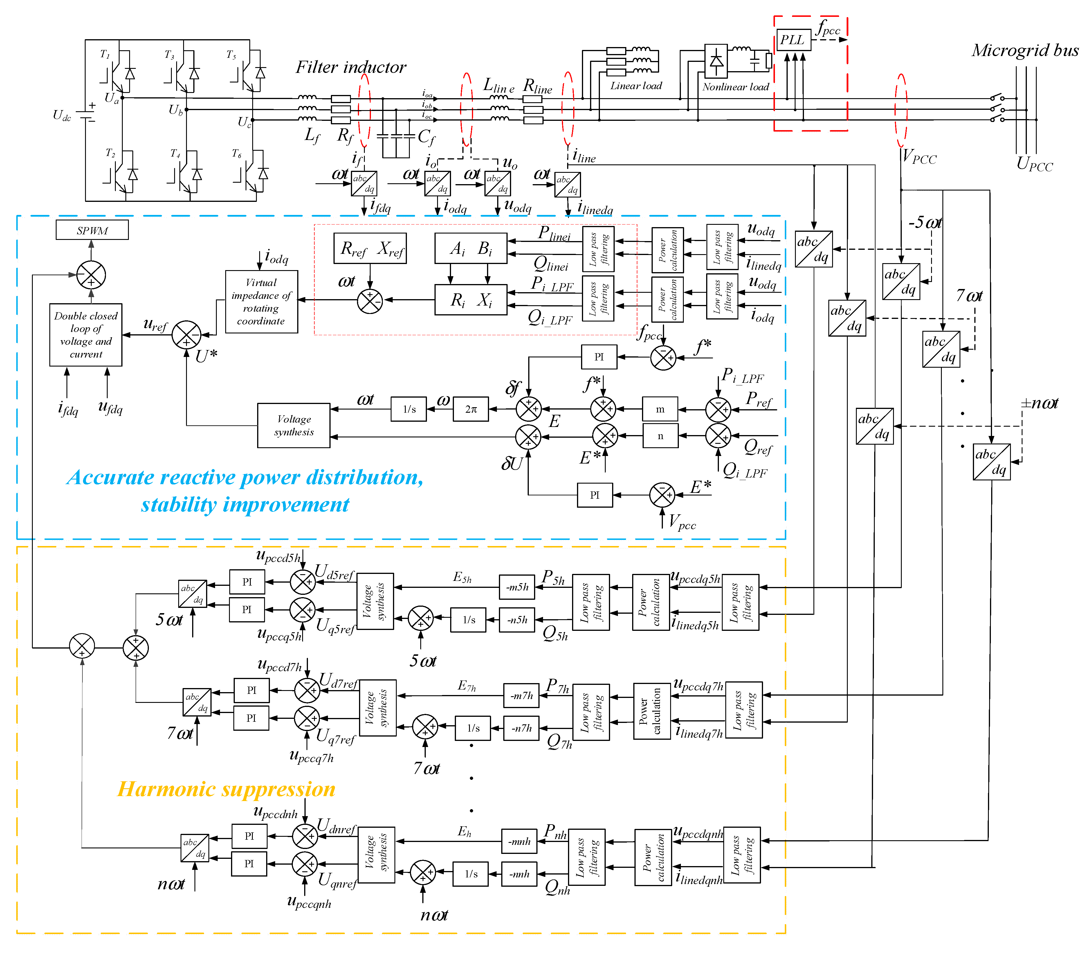
The main circuit is mainly composed of the following parts: inverter, LC filter, line impedance, linear load, nonlinear load, and so on. The inverter is controlled by a control strategy to adjust the output voltage and frequency. The comprehensive control strategy is composed of the improved fundamental control strategy and fractional frequency harmonic control strategy.
The improved fundamental control strategy is proposed upon the conventional droop control, and the problem of accurate reactive power distribution is solved by introducing virtual impedance to inverters. The secondary power balance controller is added to improve the stability of voltage and frequency. The reference value of the frequency is 50 Hz and the reference value of the output voltage is 311 V in secondary power balance controller. The voltage value and frequency of the PCC follow a given value through the closed loop control strategy.
The fractional frequency harmonic control strategy is proposed to solve the influence of nonlinear loads, micro-grid inverters, and the distribution network on output voltage of inverters, which is focused on eliminating specific harmonics caused by the nonlinear loads, micro-grid converters, and the distribution network, so the power quality of micro-grid can be improved effectively. The 5th harmonic suppression is taken as an example. Firstly, the 5th harmonic voltage and 5th harmonic current of the PCC are detected, and the harmonic power is calculated. The reference value of the output voltage of the inverter and frequency are generated according to the droop curve of the harmonic. The closed loop control strategy is adopted in the reference value and the detection value of PCC, so that the output value of the harmonic is followed by a given value, which is 0, and the 5th harmonic is eliminated. The way to suppress other harmonics is the same as the 5th harmonic. The main control block diagram is shown in
Figure 1.
In
Figure 1,
Lf is the filter inductance;
Rf is the filter resistance;
Cf is the filter capacitance;
Rline is the line resistance;
Lline is the line inductance;
Rref is the reference resistance;
Xref is the reference reactance;
Ri is the calculated value of line resistance,
Xi is the calculated value of line inductance;
Pline is the line active power;
Qline is the line reactive power;
Pi_LPF is the active power that passes through the low pass filter;
Qi_LPF is the reactive power that passes through the low pass filter;
E* is an reference voltage;
f* is an reference frequency;
Enh is the nth harmonic voltage;
Pnh is the active power of the nth harmonic; and
Qnh is the reactive power of the nth harmonic.
2.1. Combination of Adaptive Virtual Impedance Drooping Control and Secondary Power Balance Control Strategy
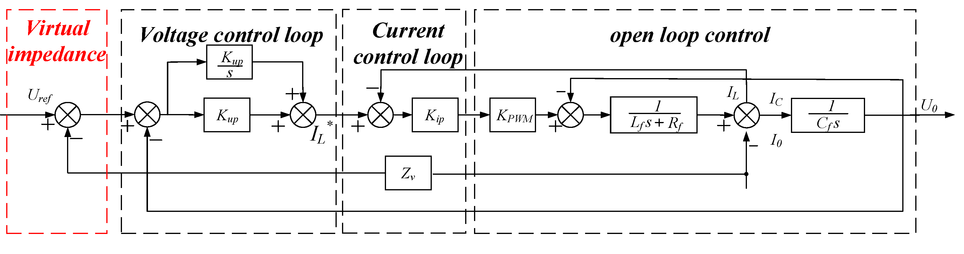
In order to achieve an accurate distribution of reactive power of inverters, an adaptive virtual impedance control loop is introduced upon conventional droop control. The control block diagram is shown in
Figure 2.
The output voltage function of the inverter with virtual impedance is:
The output power values of the inverter can be calculated by
where:
Ri and
Xi are the power equivalent output resistance and reactance, respectively, which is defined by inverter output power and the power injected to the PCC.
Zv is virtual impedance.
Based on the above circuit, the transmission line parameters and loads fluctuation will affect the value of power equivalent impedance, then influence the reactive power distribution. The power equivalent impedance can be calculated through line power.
and the inverter equivalent output impedance can be obtained by
then the virtual impedance of each micro source is calculated by
The adaptive virtual impedance control strategy can accurately distribute reactive power, meeting the requirement of the power decoupling and stability margin. The meaning of adaptive is that the virtual impedance varies along with the power equivalent output impedance when the loads change, and it can also be changed if the micro-grid central controller changes reference impedance.
The traditional droop control can realize automatic regulation of P/f and Q/V, the essence of which, however, is a kind of deviating regulation. Considering the addition of the virtual impedance will increase the degree of deviation, which is harmful to the voltage stability. Therefore, a secondary power balance control strategy is added to stabilize the output voltage of converters, as well as improve the stability of frequency. The compensation frequency and voltage of this strategy can be derived by Equations (10) and (11):
where:
f* and
f are rated frequency and operational frequency of the microgrid, respectively;
U* and
U are rated voltage and operational voltage, respectively. The frequency compensation signal
δf and voltage compensation signal
δU obtained from the secondary power balance controller are sent to each micro source, then the droop curves of micro sources will turn to be appropriate translations, then the voltage and frequency can be stabilized by adding this strategy, which is similar to the secondary frequency modulation of thermal power unit. Until now, not only can the reactive power be distributed accurately, but also the stability of voltage and frequency can be improved effectively, hence the combination of adaptive virtual impedance drooping control and secondary power balance control strategy in fundamental frequency is achieved completely.
2.2. Fractional Frequency Harmonic Drooping Control Strategy
According to the circuit superposition theorem, a linear circuit with different frequencies can be analyzed separately at each frequency. Reference [
29] confirmed that any harmonic, e.g., the
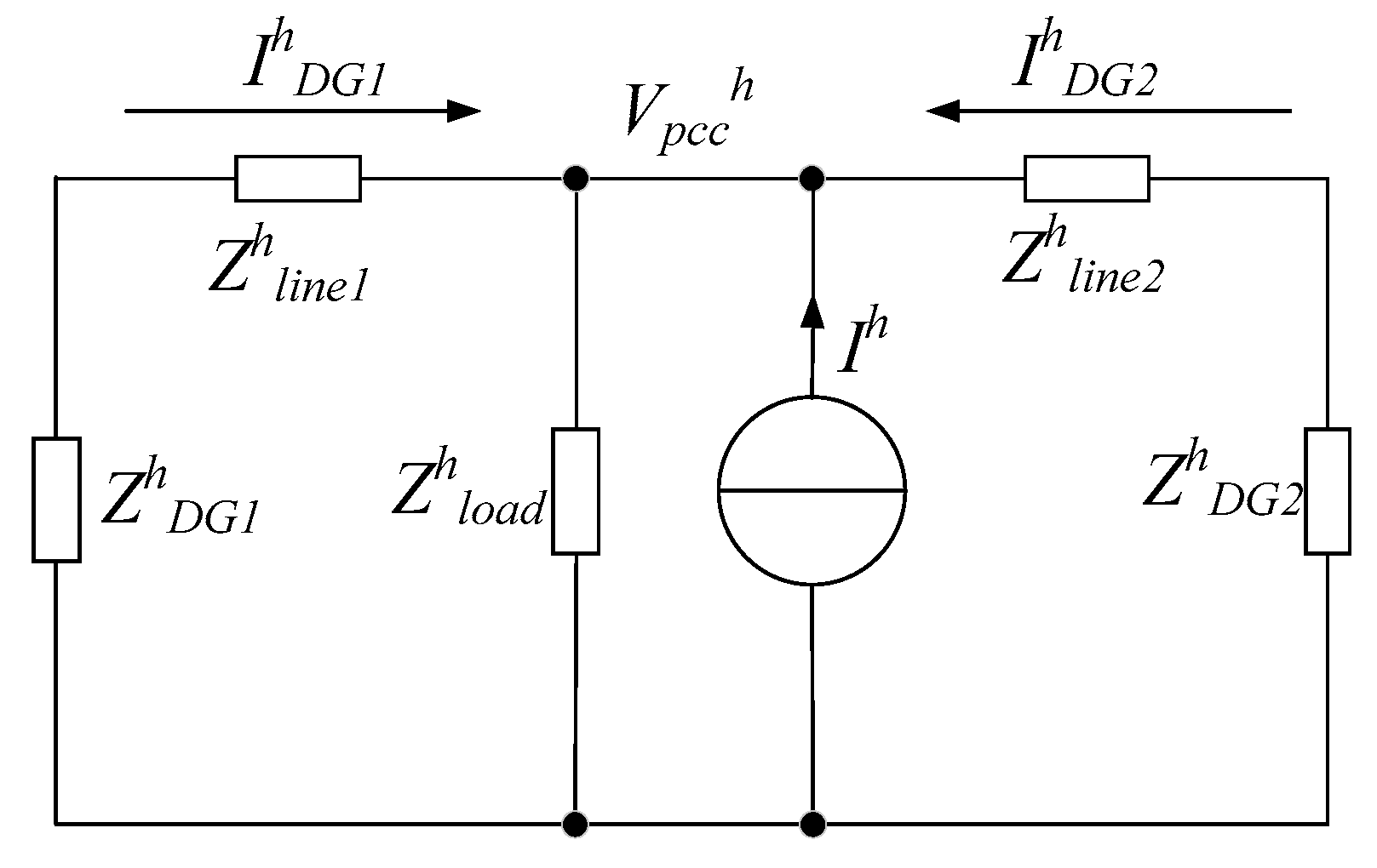
hth harmonic can be extracted for separate analysis and control when the whole system enters steady state, so the harmonic droop control strategy is proposed to eliminate the 5th, 7th, 11th, and 13th harmonics generated by nonlinear loads. In order to reduce the harmonic voltage of the system, the harmonic voltage compensation value is calculated by the harmonic droop control strategy. The system equivalent schematic is shown in
Figure 3.
In order to make the harmonic voltage of the inverter reach or close to zero, the
Voh should be zero, and the load part of the harmonic equivalent circuit can be equivalent to a current source [
30], then the output voltage of inverter can be obtained:
The phase angle difference
δ is the phase angle difference between the voltage source and the current source. When it is very small, Equations (13) and (14) can be obtained:
From Equations (13) and (14), it can be found that whether the impedance of the line is inductive, resistive, or capacitive, the correlation between
P and
E, and
Q and
δ, can be concluded. Thus the
hth harmonic droop controller can be shown as:
where:
Ph and
Qh are the calculated values of active power and reactive power under the
hth harmonic frequency;
nh and
mh are the corresponding
hth harmonic droop coefficients;
Eh is the RMS of the
hth harmonic voltage; and
ωh is the
hth harmonic voltage angle frequency. The amplitude and angular frequency of specific harmonic voltage can be eliminated by this control strategy, and the reference value of harmonic voltage on the
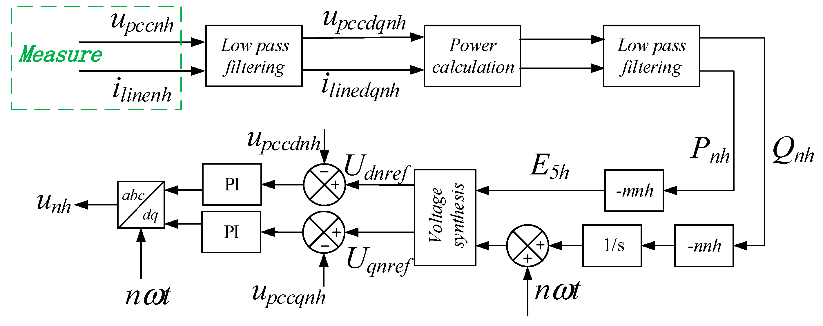
dq axis can be obtained through voltage synthesis and coordinate transformation. The modulated wave is used to turn on and turn off the inverter switch tube so as to produce the appropriate output voltage, so the PCC harmonic voltage can be suppressed effectively. The structure diagram of the harmonic drooping control is shown in
Figure 4.
3. Stability Analysis of the Multi-Converter Parallel System after Introducing the Comprehensive Control Strategy
In this section, a small signal analysis method is used to verify the effectiveness of the control strategy. The small signal analysis model of the single inverter is shown as follows (17):
where:
A single inverter model is augmented in
i = 2. The first inverter is used as the angle reference, so that the small signal model of two inverters can be obtained:
where:
where: Δ
xinv is the state variable of the inverter;
Ainv is the state matrix of the inverter; Δ
vbdq is the outlet voltage of the inverter; Δ
ωcom is a common angular frequency;
Binv and
Bωcom are the input matrix of the inverter; Δ
ω is the angle frequency of the inverter; Δ
iodq is the output current of the inverter; and
Cinvω and
Cinvc are the output matrices of the inverter.
The load is equivalent to the form of RL series for the micro-grid model, and its equivalent model is:
in which:
where:
Rload is load equivalent resistance,
Lload is load equivalent reactance, and
Iloaddq is load current.
In order to express the load-containing microgrid system in the form of state matrix, the virtual parameter
rn is introduced to replace the input of the original state space expression.
Therefore, the small signal model of the fundamental wave of the inverter model is as follows:
in which:
where: Δ
xmg is the state variable of the inverter, and Δ
Amg is the state matrix of the inverter.
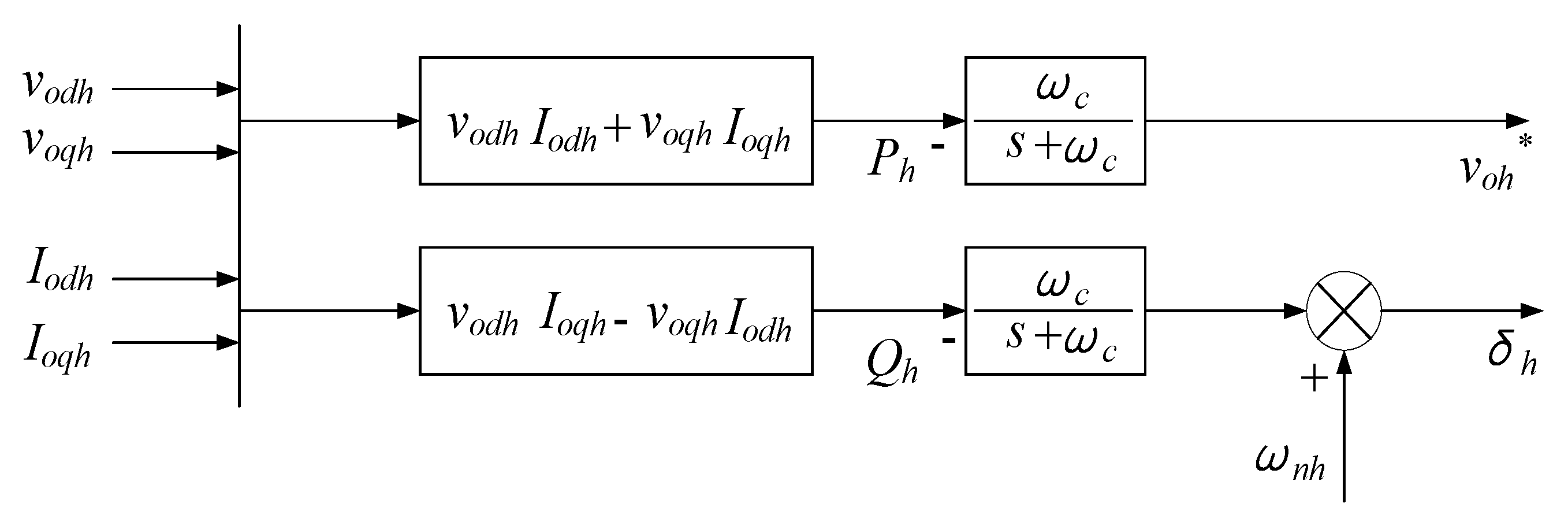
The block diagram of the harmonic droop control is shown in
Figure 5.
The harmonic droop control structure contains the harmonic power calculation module, the low pass filter module, and the harmonic droop module, which is similar to the fundamental droop control structure. The small signal model of harmonic power droop controller can be written as the form of state space function, and the expression of state space expression are:
in which:
where
vodh and
voqh represent the output harmonic voltages of inverter under
dq coordinate system;
iodh and
ioqh represent the output harmonic currents of inverter under
dq coordinate system;
Ph is the
hth harmonic active power;
Qh is the
hth harmonic reactive power;
ωc represents the cut-off frequency of the low pass filter;
mh and
nh represent the reactive and active power drooping coefficients;
ωh is the
hth harmonic angular frequency;
ωcomh is the common angular frequency under the
hth harmonic coordinate system; and
δh is the
hth harmonic angle.
The linearization of harmonic drooping voltage loop is the same as fundamental linearization.
The state space model of the harmonic droop control strategy in the multi-inverter-based micro-grid is:
The state space model of the comprehensive control strategy in the multi-inverter-based micro-grid is:
where:
xmg is the state variable under fundamental frequency;
iloaddq is a load fundamental current;
Amg is a fundamental state matrix;
xmgh is the state variable under the
hth harmonic frequency;
iloaddqh is the
hth harmonic load current;
Amgh is the
hth harmonic state matrix;
xmga is the comprehensive state variable under all frequencies; and
Amga is the comprehensive state matrix.
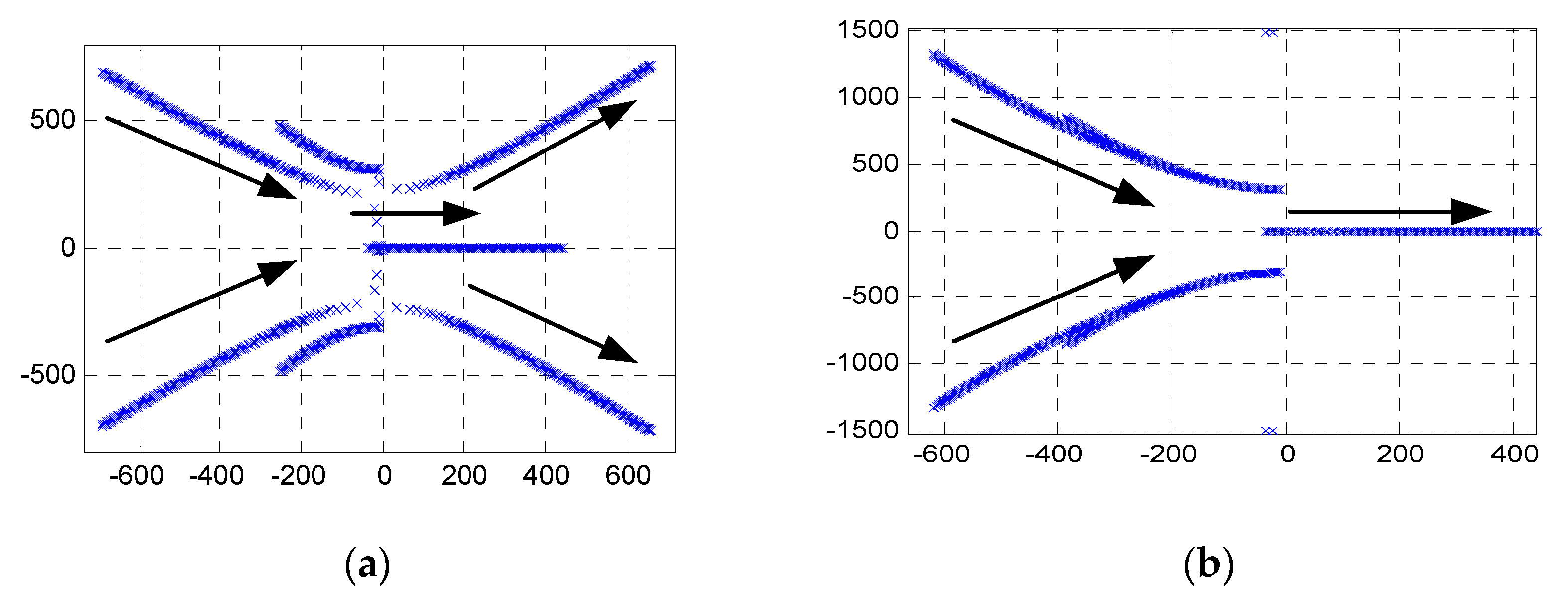
The stability simulation of the control strategy is carried out, in which the line resistance is 0.0428 Ω and the line inductance is 2.8 mH. The active droop coefficient mp = 1 × 10⁻⁵ and the reactive droop coefficient nq = 3 × 10⁻⁵. In the improved fundamental control strategy, the filter inductance is 0.6 mH, the filter capacitor is 1.5 mF, P = 1, I = 2 in PI parameters of voltage, P = 5 in PI parameters of current. In the fractional frequency harmonic control strategy, the active droop coefficient is −0.01361, the reactive power droop coefficient is −02609, KI = 10, PI = 50 in the voltage closed loop.
From
Figure 6a, when the active power drooping coefficient
mp varies from 0 to 1, the overall trend of the system root locus moves towards the right side with the increase of
mp, and reaches the right half plane eventually, and the system gradually loses its stability. Namely, the system becomes unstable if the
mp is too large. From
Figure 6b, when the reactive power drooping coefficient
nq varies from 0 to 1, the overall trend of the system root locus moves towards the right side with the increase of
nq, and reaches the right half plane eventually, and the system gradually loses its stability. Namely, the system also becomes unstable if
nq is too large.
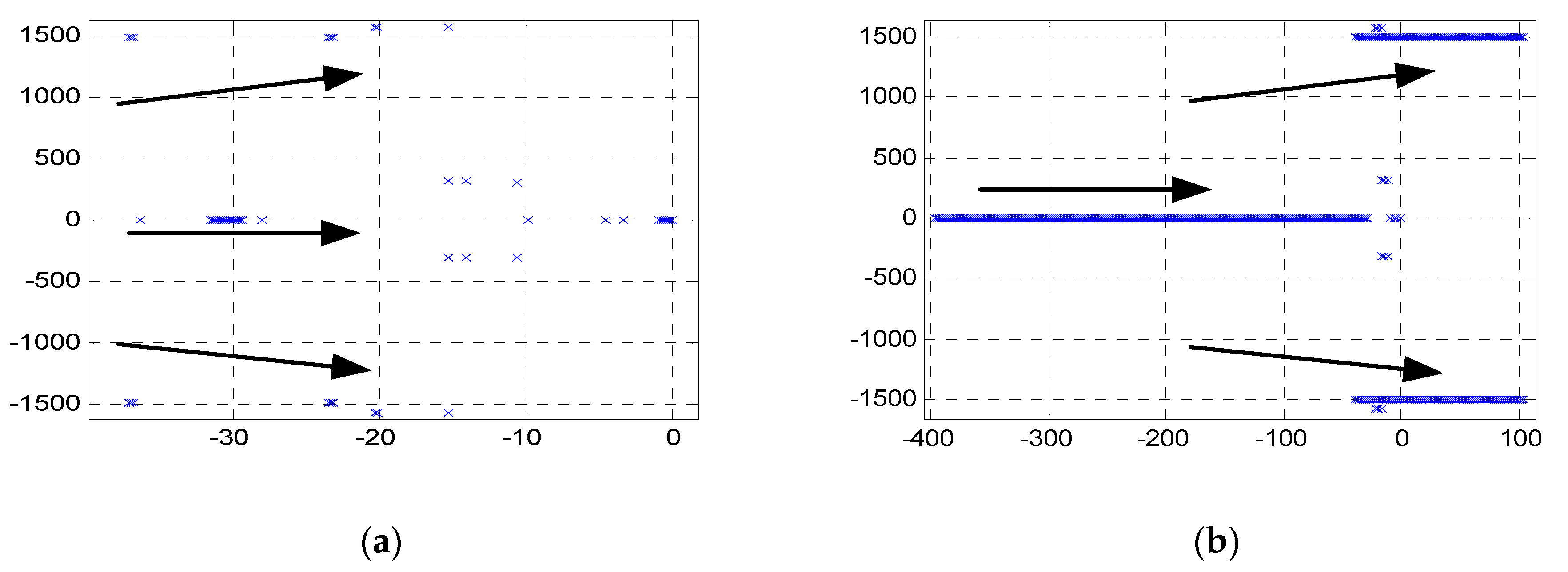
From
Figure 7a, when
mph varies from 0 to 1, the overall trend of the system root locus moves towards the right side with the increase of
mph, and the system stability is weakened gradually. From
Figure 7b, when
nqh varies from 0 to 1, the overall trend of the system root locus moves towards the right side with the increase of
nqh, and reaches the right half plane eventually, and the system stability is also weakened gradually.
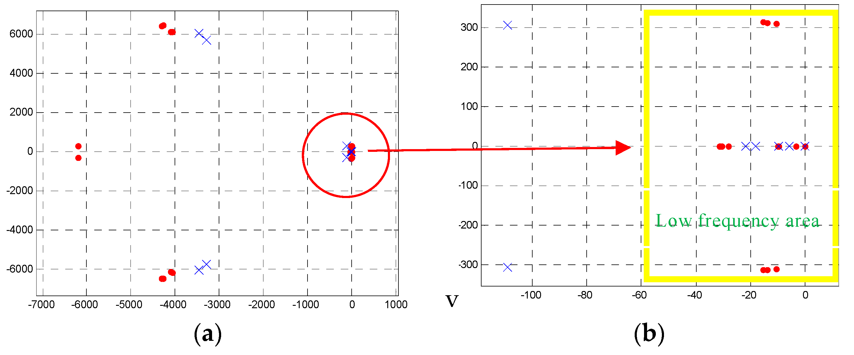
Figure 8 shows the root locus of the proposed multi-inverter-based micro-grid system with comprehensive control strategy, which proves that all eigenvalues are located in the left half plane, meaning that the system controlled by the comprehensive strategy is stable.
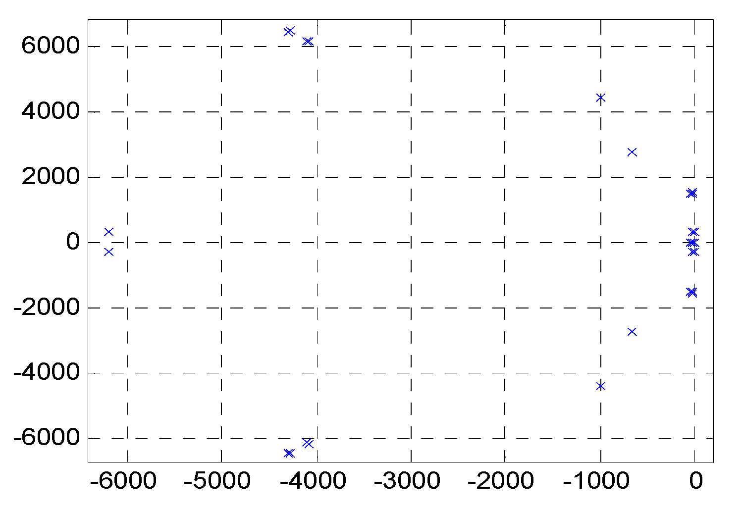
In
Figure 9, the root locus of the proposed comprehensive control strategy is represented by the red “•”, and the root locus of the conventional droop control strategy is represented by the blue “×”. The number of poles in the low frequency area of the proposed comprehensive control strategy is 13, and the conventional droop control strategy is 6 under the same parameters. The overall trend of the characteristic root of the proposed comprehensive control strategy is on the left side of the conventional droop control strategy, and the addition of three pairs of conjugate poles can enhance the rapidity of the system. The characteristic root of the proposed comprehensive control strategy and the conventional droop control strategy are all negative real roots, so the system is stable.
4. Simulation Results
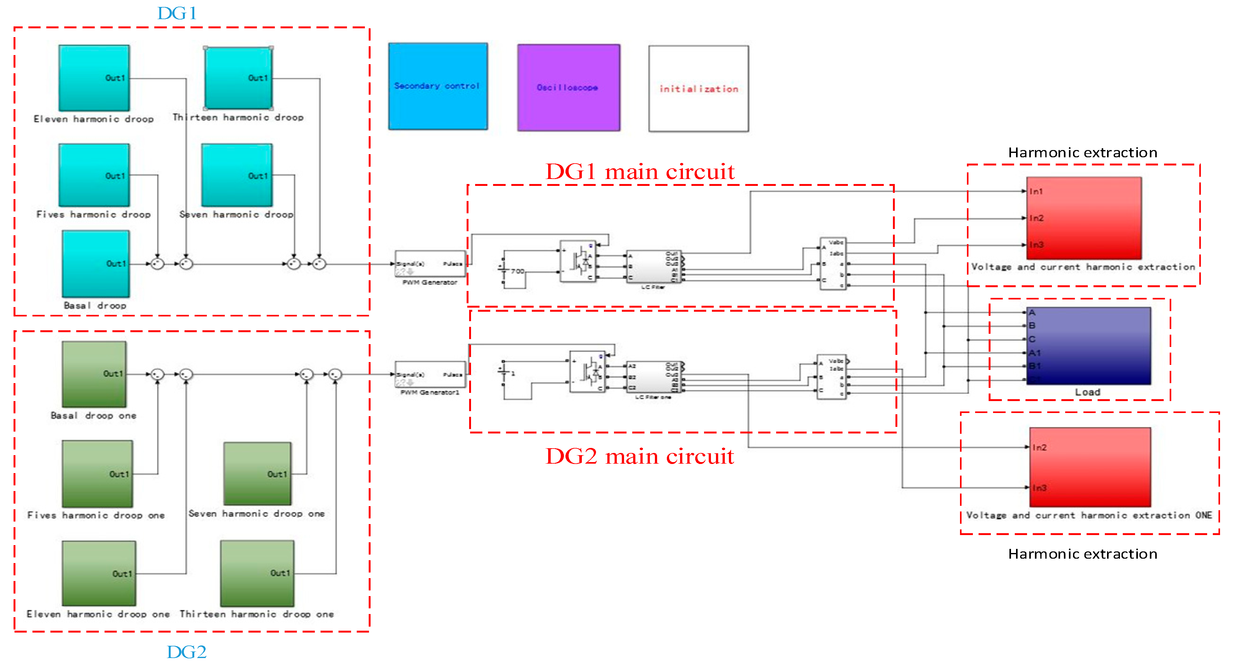
Simulations are built in MATLAB2014B, and the 5th, 7th, 11th, and 13th harmonics components are injected in the model. The simulation model is shown in
Figure 10. The inverter output phase voltage amplitude is 311 V, and the frequency is 50 Hz. During simulations, the load fluctuates abruptly at 3 s, whose active power changes from 20 kW to 40 kW, and reactive power 0 kW to 20 kW. In order to verify the effectiveness of the proposed control strategy, the simulation analysis is carried out according to the following steps:
Step 1: the conventional droop control strategy of the micro-grid is simulated. The load is changed with different line impedances while the capacities of the inverters are the same, then the simulation results can be used as a reference for the following simulation.
Step 2: the comprehensive control strategy proposed in this paper is simulated and analyzed. The load is changed with different line impedances while the capacities of the inverters are the same.
Step 3: the proposed comprehensive control strategy is also proved with different inverters capacities, the load is changed in next simulations with different line impedances, while the capacity proportion of two inverters are 2:1.
The simulation parameters used in this article are shown in
Table 1.
The results of the Step 1 simulations are shown in
Figure 11.
From
Figure 11a,b, the active powers of two inverters can be accurately distributed while the reactive powers cannot. The difference of reactive power between DG1 and DG2 is 7000 Var. In
Figure 11c,d, the voltage and frequency fluctuate when the load changes. The values of voltage and frequency cannot be stabilized at 311 V and 50 Hz. The phase voltage reduction is 215 V, and the frequency reduction is 49.82 Hz. Meanwhile, the voltage waveform distortion in the 5th, 7th, 11th, and 13th harmonics are obvious. The 5th harmonic is 1.8%, 7th harmonic is 1.7%, 11th harmonic is 1.2%, and 13th harmonic is 0.7%.
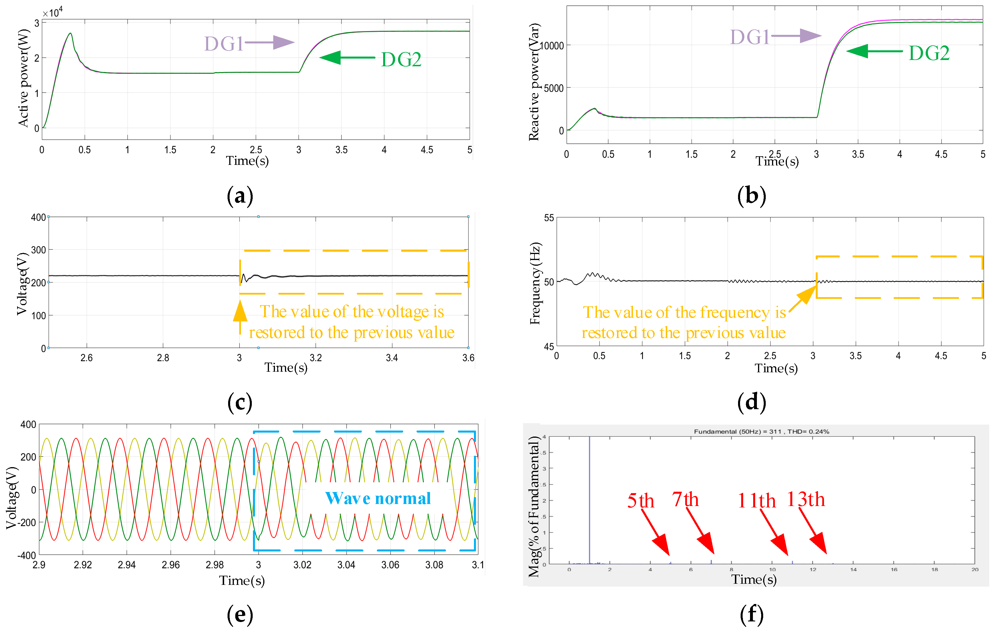
The results of the Step 2 simulations are shown in
Figure 12.
With the comprehensive strategy, the improvement of reactive power distribution is obvious in
Figure 12b. In
Figure 12c,d, the voltage and frequency can be stabilized at 311 V and 50 Hz while the load changes. The waveform has been significantly improved in
Figure 12e, and the 5th, 7th, 11th, and 13th harmonic components are suppressed in
Figure 12f. The 5th harmonic is 0.02%, 7th harmonic is 0.02%, 11th harmonic is 0.01%, and 13th harmonic is 0.02%.
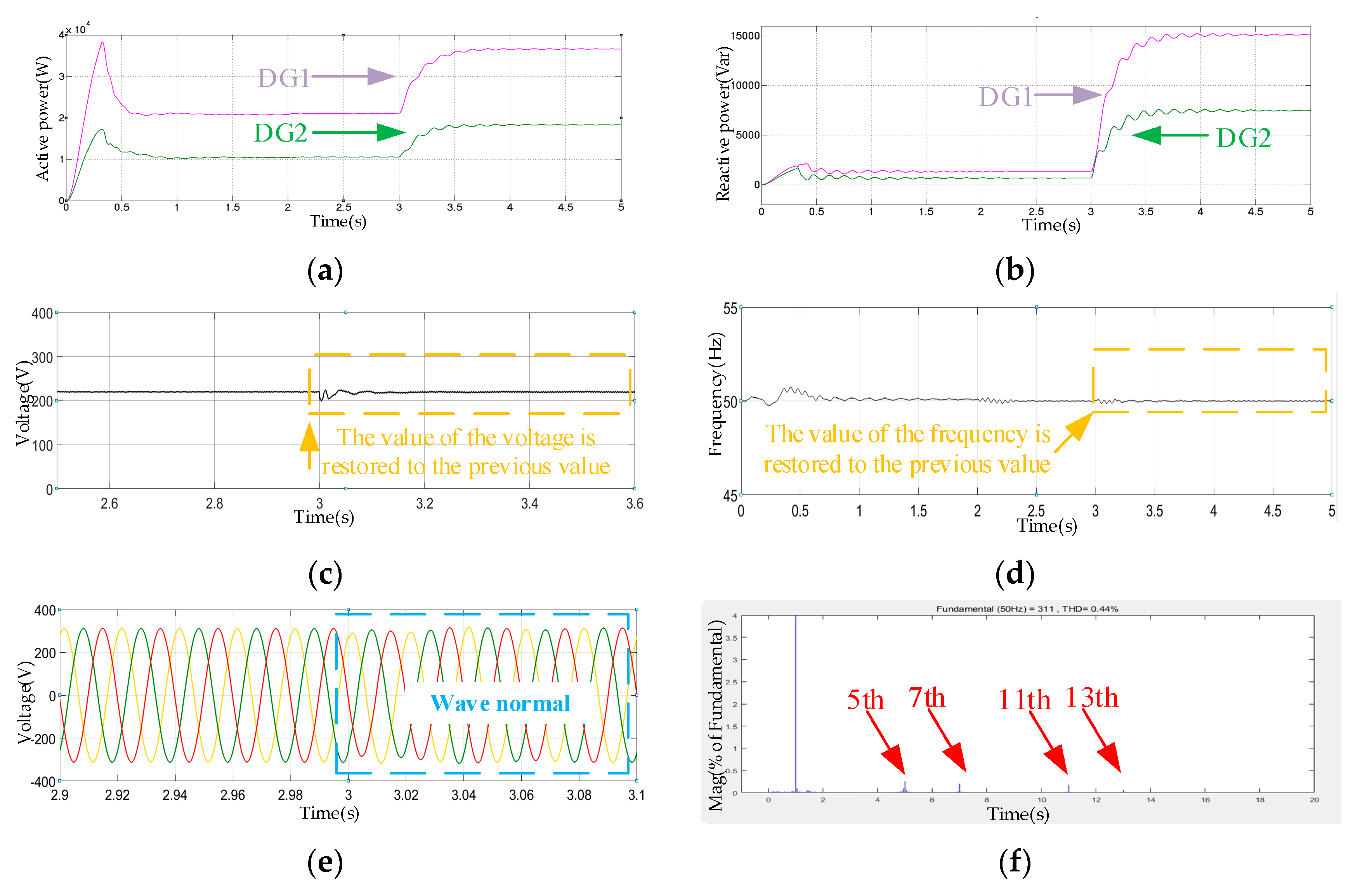
The results of the Step 3 simulations are shown in
Figure 13.
The experimental results of simulation 3 are similar to those of simulation 2. The 5th, 7th, 11th, and 13th harmonics are almost completely eliminated by simulation 2 and simulation 3. The effect is shown in
Table 2. There is no doubt that the proposed strategy is also effective for the system with different micro sources capacity proportions.
According to these three simulations, it can be seen that the comprehensive strategy this paper proposed can guarantee the accurate distribution of active power and reactive power between micro sources. The voltage and frequency can be stabilized at 311 V and 50 Hz while the load changes. Meanwhile, the 5th, 7th, 11th, and 13th harmonics components can be effectively suppressed. The effects of these three simulations are shown in
Table 3.


