New Method to Analyse the Cement Sheath Integrity During the Volume Fracturing of Shale Gas

College of petroleum Engineering, China University of Petroleum (Beijing), Beijing 102200, China
*
Author to whom correspondence should be addressed.
Energies 2018, 11(4), 750; https://doi.org/10.3390/en11040750
Submission received: 20 January 2018
/
Revised: 21 March 2018
/
Accepted: 22 March 2018
/
Published: 26 March 2018
Abstract
:Accurate prediction of the hoop stress distribution of the cement sheath and its variation regularities during volume hydraulic fracturing in shale formations is of great significance for maintaining the wellbore integrity of shale gas horizontal wells. A finite element model of casing-cement sheath-formation system (CCFS) coupling between stresses and temperature was established through a staged finite element method based on the elastic anisotropy of shale. With this new model, the effects of operation parameters and formation mechanical property changes on the cement sheath hoop stress during the multi-stage hydraulic fracturing process were analyzed, and the results were compared with the conventional model. The results revealed that the increase of the temperature of the fracturing fluid could reduce the hoop stress of the cement sheath, which decreased gradually with the decreasing elastic modulus of the cement sheath, and eventually changed to compressive stress from tensile stress. The hoop tensile stress of the cement sheath increases first and then tends to decrease with the increasing internal casing pressure, the larger the local formation stress, the smaller the pore pressure and the smaller the hoop tensile stress of the cement sheath it preforms. The findings of this paper are of great guiding significance to the research of the cement sheath stress variations during volume fracturing in shale formations and to the optimization of fracturing design.
1. Introduction
In the oil field development process, the cement sheath is an essential barrier that maintains the normal production of oil and gas wells. Failure of the cement sheath integrity will cause the casing to lose its protection and threaten the wellbore integrity further. From the analysis of shale gas fracturing operation characteristics, it is found that more than 10 sections of the horizontal well will be stimulated during the volume fracturing process. Moreover, as the single section perforation interval is rather long, the stimulation scale is larger. With the rapid injection of large displacement fracturing fluid, the wellbore temperature drops rapidly. Multistage fracturing operation not only results in repeated cyclic changes of pressure and temperature in the wellbore, but also leads to subsequent changes in the fracturing mechanical environment. The characteristics of the operation may induce the hoop tensile damage of the cement sheath in the fractured and upper reservoir sections to form radial cracks. The structural damage of the cement sheath will aggravate the risk of casing failure. Therefore, an accurate grasp of the cement sheath stress variation in the multistage fracturing process is of great significance to maintaining the wellbore integrity of shale gas wells and to ensuring the normal progression of subsequent operation [1].
Regarding the analysis of wellbore integrity under normal conditions, some scholars have carried out studies through laboratory tests, numerical simulations, and analytical modeling approaches [2,3,4,5,6]. They concluded that the wellbore trajectory, non-uniform geo-stress, cementing quality, thermal stress and fracturing operation parameters are the main factors influencing the stress variation of the casing-cement-formation system (CCFS).
However, unlike fracturing of homogeneous formations, volume hydraulic fracturing in shale reservoirs is practiced in formations with strong anisotropy, and is accompanied by drastic variations in temperature, pressure and formation properties. To address the present wellbore integrity problem in shale formation, Tian et al. established a multi-factor coupled casing stress calculation and evaluation model [2]. They claimed that the casing damage of shale gas wells was a result of the coupling of multiple factors such as temperature effect, casing bending, and axial pressure. Daiconcluded that the casing deformation in the fractured formation was attributable mainly to the weakening of the casing strength caused by the bending stress, strength fatigue and casing damage and external load variations caused by the changes in nearby in-situ stress field and local stress formed after failure of cement sheath based on the characteristics of well testing and completion operation of shale wells in Sichuan [7]. Sugden et al. researched the design of oil casings for shale gas horizontal wells. They conducted transient thermal analysis by using the Landmark’s commercial analysis software WellCAT and also analyzed the effects of aggressive trajectories, multistage high rate fracturing, and increasing pressure of shale reservoirs on the casing stress. Their results suggested that the fracturing operation would reduce the bottom hole temperature rapidly, and the thermal stress induced by the rapid temperature change in combination with the high-pressure environment of bottom hole leads to significant change in the casing stress state [8].
In summary, it can be seen that the aforementioned studies emphasized on the casing integrity while ignoring the analysis of the cement sheath integrity in facing the wellbore integrity problem of the shale formation. Besides, all the finite element models or analytical models built considered the casing, cement sheath and formation as an integral whole and applied internal pressure and in-situ stress on the inner and outer model boundaries. However, this approach has a limitation, which is being unable to consider the stress distribution variation of CCFS from well construction to hydraulic fracturing. Moreover, all the previous studies ignored the elastic anisotropy of shale formation and thus could not accurately describe the variation regularities of the cement sheath hoop stress during the multi-stage fracturing in shale formation.
To this end, we established a finite element numerical mechanical model of CCFS based on the staged finite element method, which considered the stress variation of CCFS from well construction to hydraulic fracturing, to comprehensively analyze the influences of operation parameters and stratigraphic changes on the cement sheath stress.
2. The FEM Model of the Casing-Cement Sheath-Formation in Shale Formation
2.1. Anisotropic Elastic Constitutive Model of Bedding Shale
In engineering, shale is considered as a typical bedding formation, so it can be deemed as a transversely isotropic material that can be described by five independent elastic constants. Its stress–strain constitutive equations are as follows:
where denotes the elastic modulus parallel to the isotropic plane (); denotes the elastic modulus perpendicular to the isotropic plane (); denotes the Poisson’s ratio parallel to the isotropic plane; and denotes the Poisson’s ratio perpendicular to the isotropic plane. The shear modulus within the isotropic plane XOZ is:
where denotes the shear modulus parallel to the isotropic plane (); denotes the elastic modulus parallel to the isotropic plane (); and denotes the Poisson’s ratio parallel to the isotropic plane. The fifth elastic constant perpendicular to the isotropic plane is [9]:
2.2. The Traditional Model of CCFS
For the traditional model, there is only one step in the simulation process (Figure 1). The traditional model ignores the stages of a wellbore life before the hydraulic fracturing operation. Before the model is established, the following assumptions are made:
- (1)
- The casing, cement sheath and formation are all homogeneous isotropic materials;
- (2)
- The casing, cement sheath and formation are completely cemented;
- (3)
- No initial stress exists in the cement sheath;
2.3. The Staged FEM Method
For convenience of calculations, this paper makes the following assumptions: in the analysis step of the cementing, the cement slurry instantly solidifies and changes into the cement sheath, at which point the cement sheath already has the initial stress. Further analysis is conducted on this basis. Compared to the traditional model, this present model is closer to the actual situation. The simulation can be divided into four stages as shown in Figure 2:
- As a first step, apply far-field stress and pore pressure to the formation, then the stress field is balanced.
- As a second step, drilling is simulated, and drilling fluid column pressure is imposed on the borehole wall to simulate the wellbore deformation and stress state during the drilling process.
- As a third step, cement sheath and casing are added simultaneously to the model, then the outer cement sheath boundary matches exactly with the deformed borehole.
- As a fourth step, pressure load is applied on the interior wall of the casing to simulate the downhole condition changes during the subsequent operations. The interface of cement sheath is simulated with the interface elements-based on the Coulomb friction model.
Since transverse isotropy is a characteristic of bedding shale, the orientation of rock material should be defined after parameter determination in the numerical modeling process. Thus, the local coordinate system of the material is established. For ease of analysis, the local coordinate system of the material is consistent with the original coordinate system (that is to say, X–X’, Y–Y’ and Z–Z’). In the model, XZ plane corresponds to the isotropic plane, while Y axis is perpendicular to the isotropic plane. The X axis direction is the direction of horizontal minimum principal stress, whereas Y axis direction is the direction of horizontal maximum principal stress (Figure 3).
2.4. Failure Criterion of Cement Sheath
During the fracturing process, excessively high pump pressure may cause the hoop stress of cement sheath to exceed the tensile strength to induce tensile failure, so the cement sheath loses structural integrity. In this paper, the maximum principal tensile stress criterion is used to determine whether the sheath is damaged or not .The criterion is as follows:
where is the maximum hoop stress on the circumference of the cement sheath, MPa; and is the tensile strength of the cement sheath, MPa.
2.5. Model Verification
Based on the logging data before cementing, calculate the original shape of the well. Then, based on the logging data after cement solidification and the original shape of the wellbore and casing, the deformation of the wellbore and casing is calculated, and the original shape of the cement sheath is calculated by the deformation amount.
- (1)
- Calculation of formation radius:
In the formation, the current displacement field and stress field should be the superposition of the initial displacement field (zero) and the initial stress field (original in-situ stress) and the disturbance field.
According to the elastic theory, the inner radius can be changed as follows:
where ; ; ; ;
The variation of formation radius is expressed as:
where is the measuring radius.
Then, the formation radius (drilling) can be expressed as:
Furthermore, the outer diameter of cement sheath is equal to the wellbore radius.
The formation radius can be solved:
- (2)
- Stress distribution and displacement change of assembly after cementing
After the solidification of cement, the inner pressure of the inner wall of the cement sheath is subjected to internal pressure pci. The pressure value is the external pressure value of the casing because the casing is tightly attached to the inner side of the cement sheath. The variation of casing radius can be solved:
Then, the outer diameter of the casing is expressed as:
where Pmi = Pci.
The inner diameter of the cement is expressed as:
The inner diameter of cement ring is expressed as:
where rs1, rs2 are the original diameter of the cement sheath, m.
Through the above calculation, the stress distribution of the CCFS after cementing and the size of the CCFS can be obtained.
- (3)
- Stress distribution of CCFS during hydraulic fracturing
During the hydraulic fracturing, the internal casing pressure changes, and the stress of CCFS is equal to the superposition of the stress change of the CCFS caused by the change of internal pressure and the stress state of CCFS after cementing operation. As for the analytical model, the following assumptions are made [10]:
- (1)
- The casing, cement sheath and formation are all homogeneous isotropic materials;
- (2)
- The casing, cement sheath and formation are completely cemented;
So according to the theory of displacement continuity, it can be obtained:
where in the internal pressure variation (MPa); is the stress variation at first interface (MPa); is the stress variation at second interface (MPa); , are unknown parameters (MPa).
Then and can be solved. According to the superposition principle, the excavation model of the CCFS considering the initial stress of the cement sheath can be obtained.
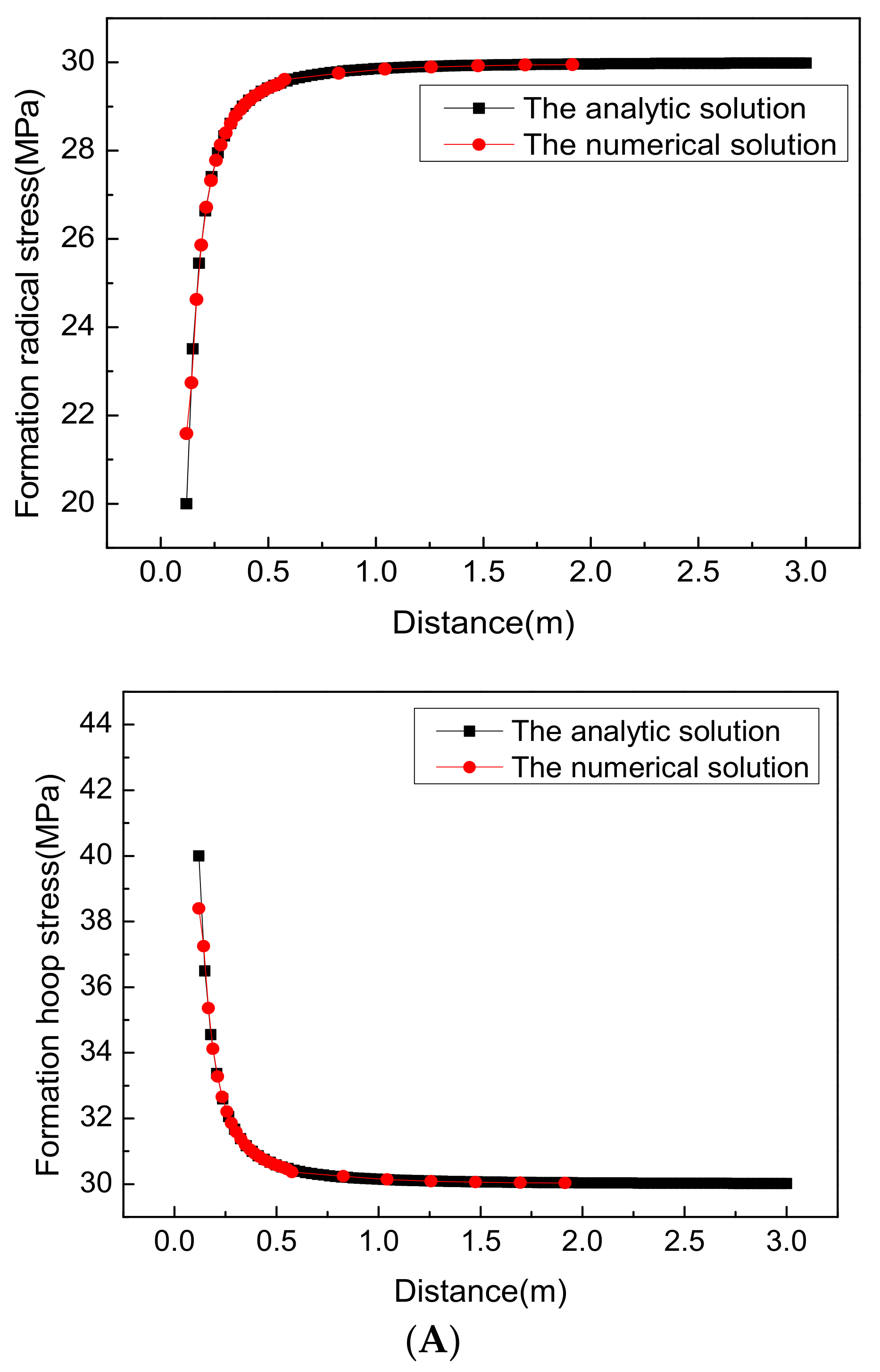
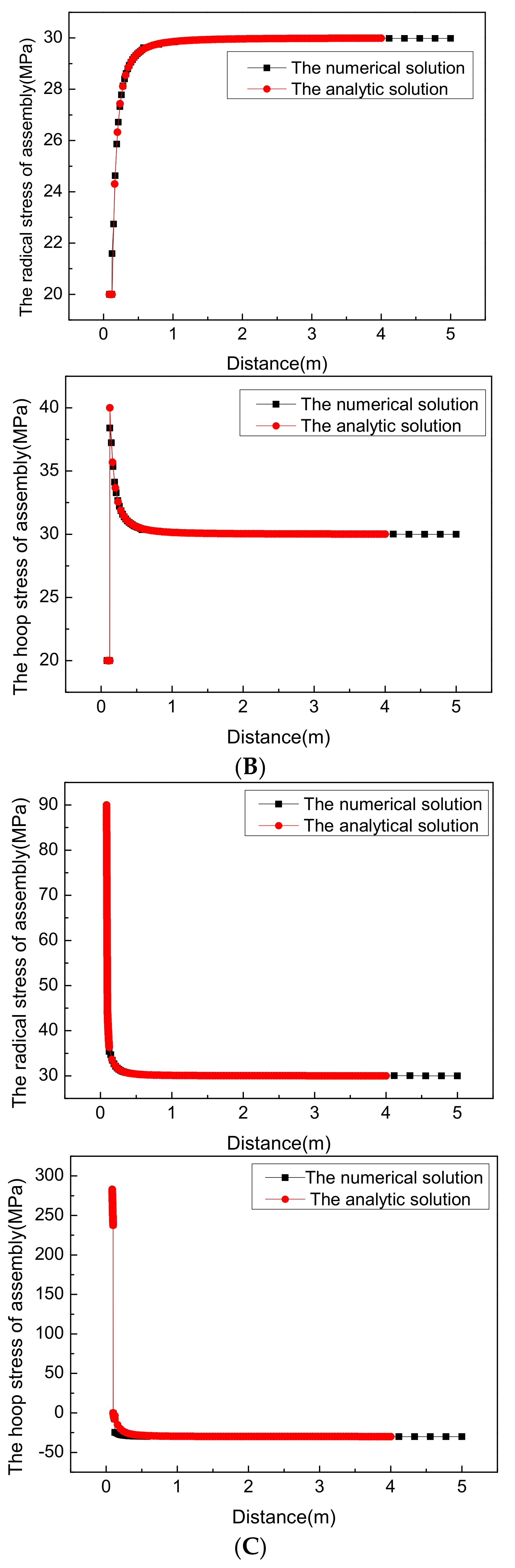
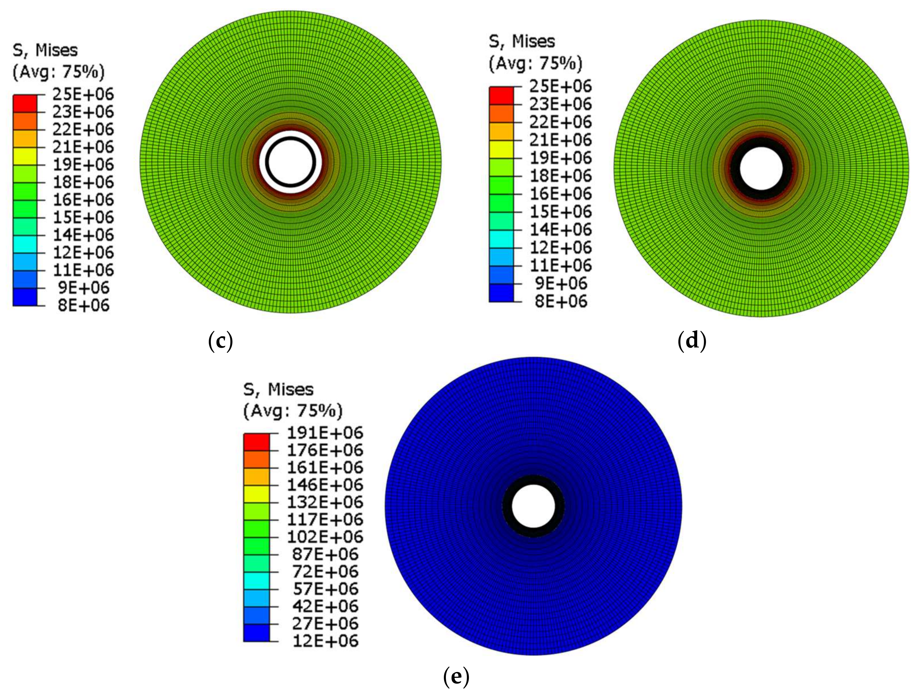
When p = q, the model is degenerated into a model under uniform in-situ stress, in which . A numerical example is given to verify the rationality of the model. The numerical and analytical results show that the numerical simulation is in good agreement with the analytical model, indicating that the numerical model established in this paper is reliable (Figure 4).
3. Case Study
The parameters of the model are taken from a fractured well located in the Weiyuan area. The values of five engineering elastic mechanical parameters for shale material are set as follows: Poisson’s ratio and elastic modulus perpendicular to the isotropic plane are = 0.2 and = 20 respectively; Poisson’s ratio and elastic modulus parallel to the isotropic plane are = 0.18 and = 17 , respectively; and , are solved using Equations (3) and (4). The formation parameters are as follows: Permeability of formation fluid 0.1 × 10⁻³ μm3; porosity 3%; fluid saturation 1; reservoir fluid density 1 g/cm3; the pore pressure 10 MPa; overburden pressure 30 MPa; minimum horizontal principal stress 24 MPa; and maximum horizontal principal stress 30 MPa. The geometrical parameters, material properties and thermodynamic parameters of the model are listed in Table 1 and Table 2. In this paper, the maximum principal tensile stress criterion is used to determine whether the sheath is damaged.
Numerical simulation was performed on the CCFS by using the staged finite element method. In view of the fact that the temperature field of the CCFS would change dynamically with the alternation of fluid injection and pumping termination in the staged fracturing operation process of shale gas well which results a temporal variation of load during the transient heat transfer. Therefore, 12 time incremental steps were set up for the model herein [11,12,13]. Fluid injection and pumping termination were carried out alternately, where the injection time was 1h, the pumping termination time was 2 h, and the total length of time was 18 h. Model parameter setting: (1) Initial formation temperature is 100 °C; during the winter, since the injection fluid temperature will be lower than summer, so the injection fluid temperature is set to 0 °C. The results of staged finite element calculation are shown in Figure 5.
For the traditional model, the initial values of elastic mechanical parameters for shale material are set as follows: Poisson’s ratio and elastic modulus perpendicular to the isotropic plane are v = 0.2 and E = 20 GPa, respectively. The initial boundary condition is same as the staged FEM model.
3.1. Effect of Temperature Variation
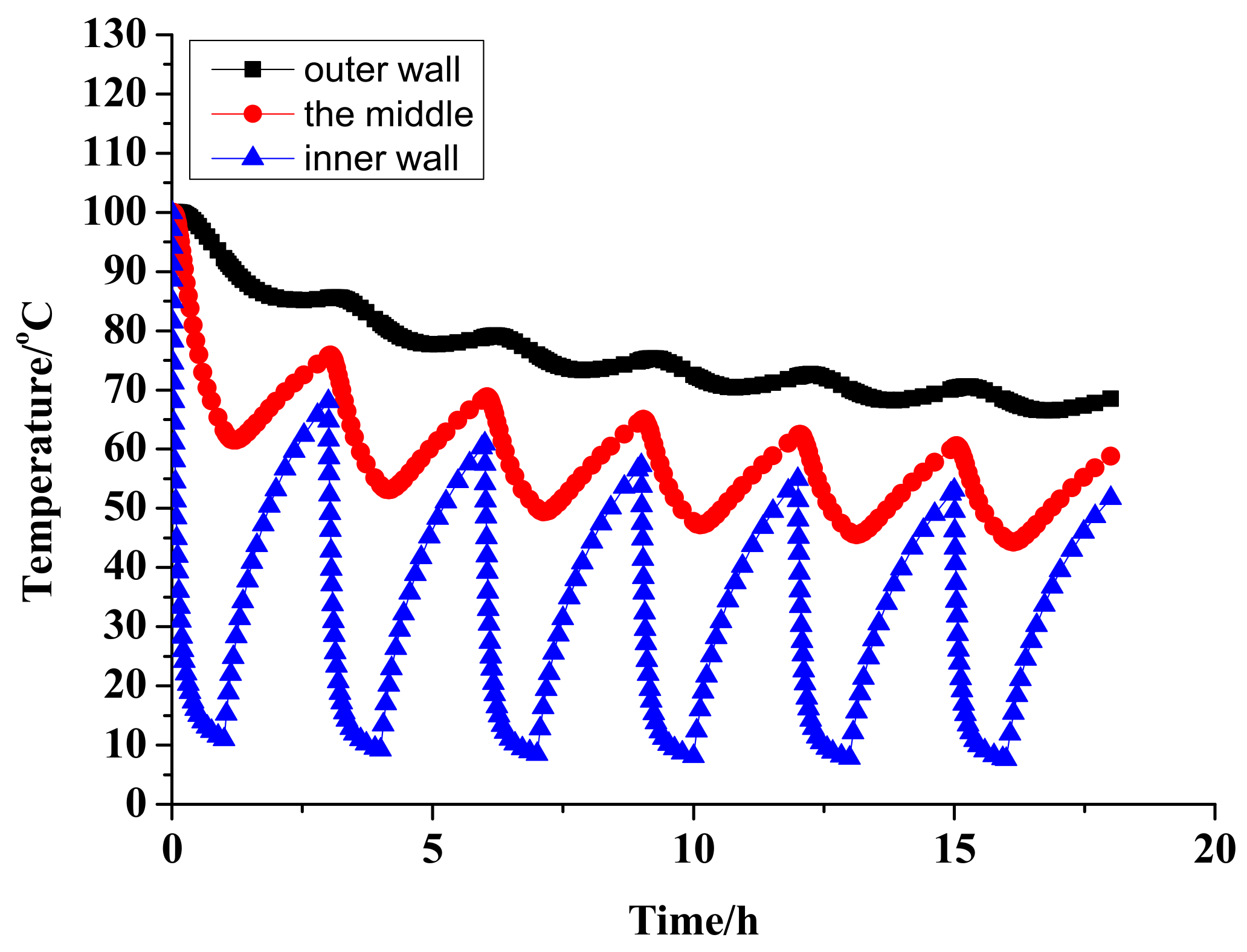
Figure 6 presents the temperature variations of the inner wall, central part and outer wall of the cement sheath over time. During the cyclic injection process, the temperature difference between the inner and outer cement sheath walls was up to 75 °C. As the thermal conductivity of cement sheath was lower than the casing, the temperature fluctuation amplitude of cement sheath decreased gradually with its increasing radial distance, of which the outer wall temperature exhibited an overall slow decline trend.
Figure 7 presents the hoop stress variation curve over temperature calculated using the staged finite element model and its comparison with results calculated using the conventional finite element model. The results reveal that the hoop stress of cement sheath increases with the decreasing injection fluid temperature, which increases the risk of tensile damage on the inner wall of the cement sheath. As the number of operation times increases, the temperature of the cement sheath when the pump stops gradually approaches the injection fluid temperature, and the hoop stress of the cement sheath caused by temperature stress increases continuously to increase the risk of tensile failure of the cement sheath in the subsequent operation process.
Meanwhile, the comparison of results under conventional model versus staged finite element model clearly found that the hoop stress was higher than the conventional model at an injection temperature of 0 °C. Thus, the use of conventional model during the high-pressure fluid pumping into the wellbore would greatly underestimate the changes in the hoop stress of cement sheath.
3.2. Effect of Internal Pressure Variation
Figure 8 presents the influencing regularities of internal casing pressure on the cement sheath hoop stress under the two models. Clearly, the hoop stress of cement sheath increased first and then decreased with the increasing internal casing pressure; besides, the variation trends of hoop stress were consistent under the two models. It was also found that there existed a pressure in the process of raising pump pressure which maximized the hoop stress of cement sheath within the wellbore. It is also found that the hoop stress obtained via the conventional model is far less than that the approach taking the practical operation process into consideration. During the fracturing operation, the pump pressure should be adjusted appropriately to avoid the increase of hoop tensile stress of the cement sheath.
3.3. Effect of In-Situ Stress on the Stress of Perforated Casing
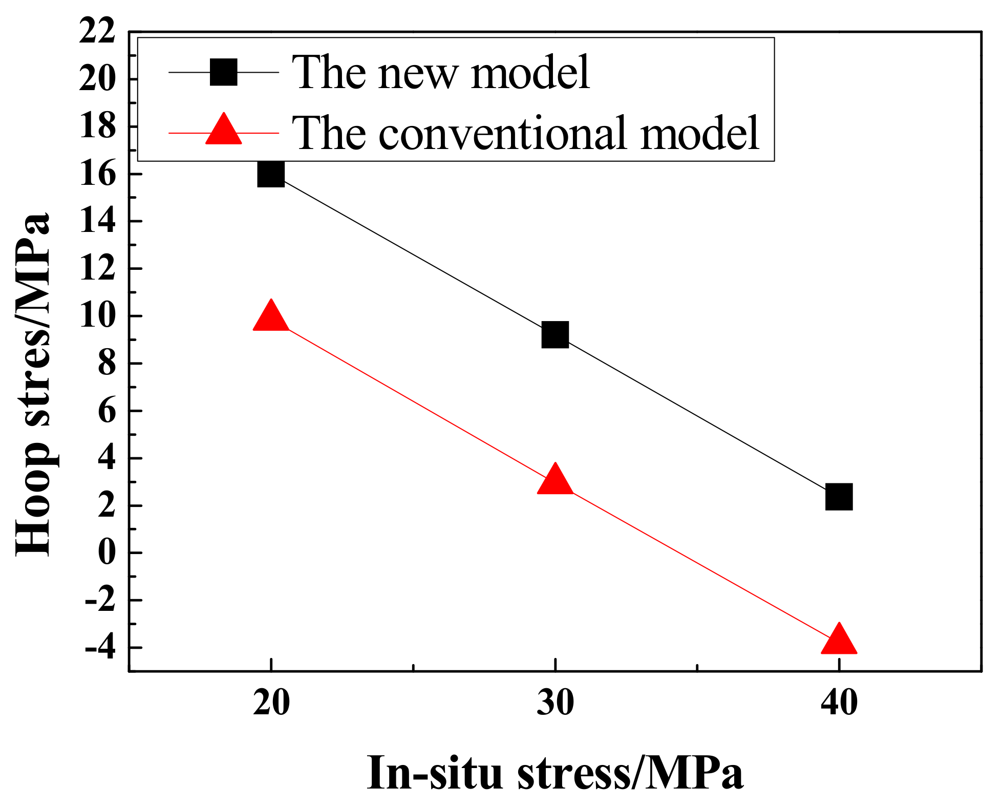
During the fracturing process of shale reservoirs, the fracturing fluid is pumped into the formation, and the local in-situ stress field around the wellbore can be altered by fluid injection in fracturing operations of adjacent wells [14]. Figure 9 presents the influence of in-situ stress variation on the cement sheath hoop stress under the two models. The results showed that the hoop tensile stress of the cement sheath decreased gradually with the increasing in-situ stress, that is, the risk of tensile failure was reduced.
3.4. Effect of Pore Pressure
During the multistage hydraulic fracturing process, the infiltration of fracturing fluid into the formation will change the local pore pressure of the formation around the wellbore. Figure 10 presents the influence of formation pore pressure variations on the cement sheath stress under the two models, the hoop tensile stress of the cement sheath increased gradually with the increasing local pore pressure in the formation. It can thus be seen that influence of formation pore pressure on the cement sheath stress state was non-negligible during the fracturing process, whose result might lead to the early failure of the cement sheath in the non-fractured section to affect the determination of subsequent operation parameters.
3.5. Effect of Formation Properties
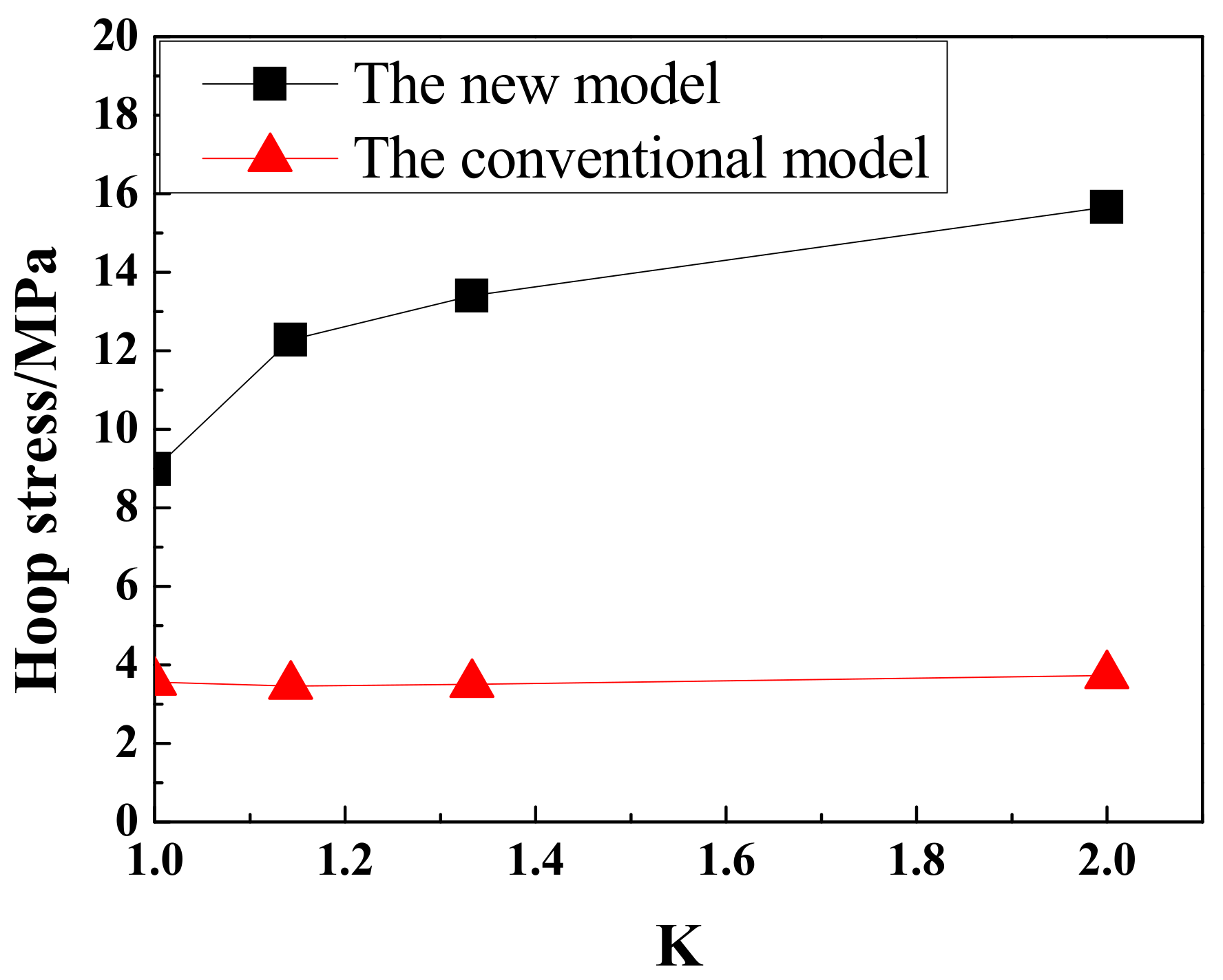
The anisotropy index K refers to the ratio of elastic modulus to the normal elastic modulus of the shale bedding plane. The greater the value, the higher the degree of anisotropy. The influence of formation anisotropy on cement sheath stress is shown in Figure 11. For the conventional model, the formation anisotropy has little effect on the hoop stress of the cement sheath during high-pressure fluid injection. As for the staged finite element model, the hoop tensile stress of the cement sheath increases rapidly and then slowly with the increasing anisotropy. This is because the anisotropic characteristic of the formation’s elastic modulus changes the stress distribution around the wellbore and exacerbates the distribution non-uniformity of formation geos-tresses, which leads to slightly increased hoop tensile stress of the cement sheath. Next, during the stimulation of shale reservoir, hydraulic fractures will communicate the bedding and natural fractures in the formation to form a complex fracture network. The formation of fracture network in the formation will lead to a decrease in the integrated elastic modulus of formation [15].
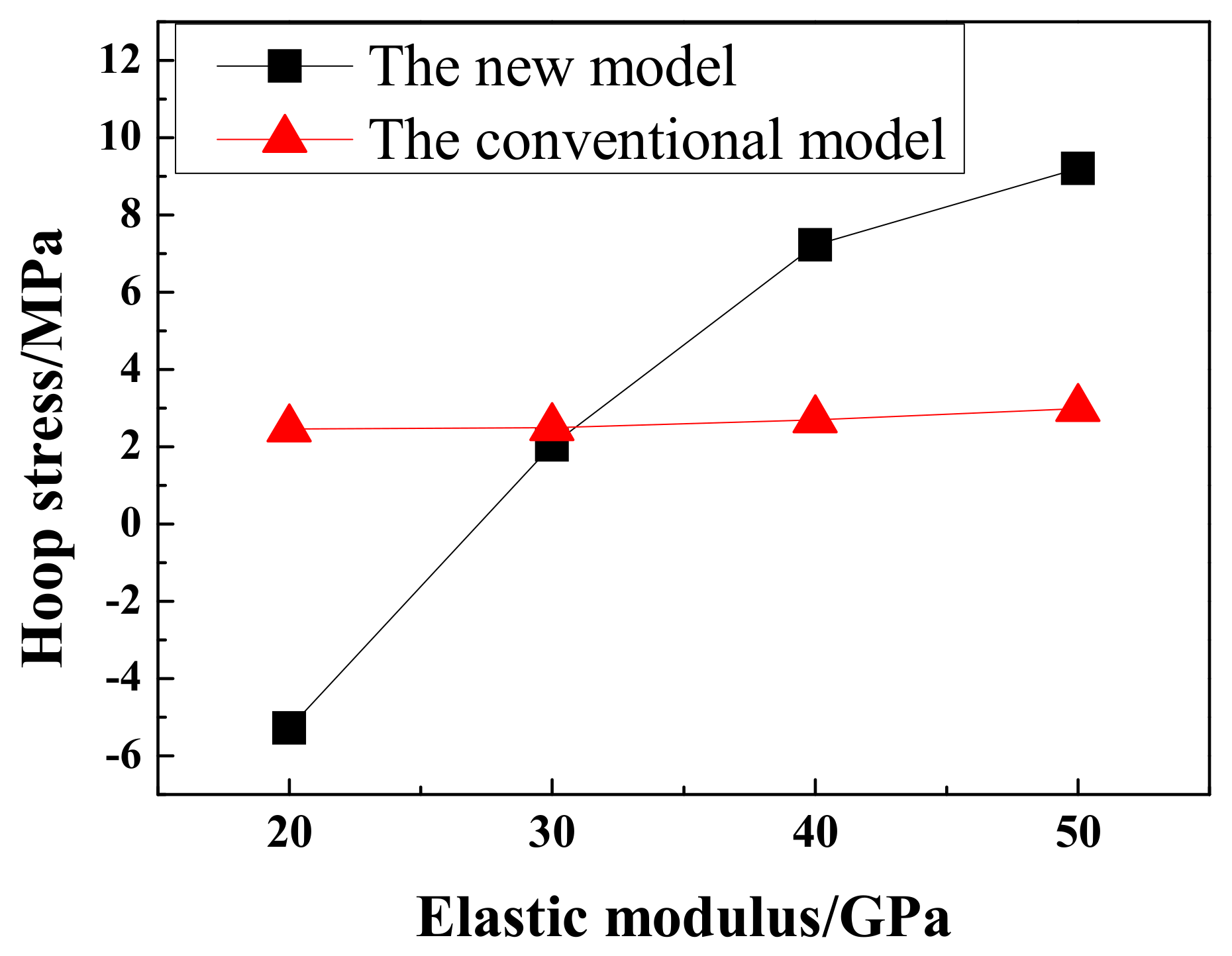
Figure 12 presents the influence of formation elastic modulus on the cement sheath hoop stress. For the conventional model, the hoop tensile stress of cement sheath decreased gradually with the decreasing elastic modulus of the formation. As for the staged finite element model, the hoop stress of cement sheath increased slightly with the decreasing formation property. Thus, the use of the conventional model in the actual operation may lead to misjudgment of the actual situation. Adjustment of perforation parameters and optimization of operation design should be based on the actual formation conditions, so as to avoid over-stimulation of the formation from increasing the geo-stress non-uniformity.
3.6. Effects of Cement Properties
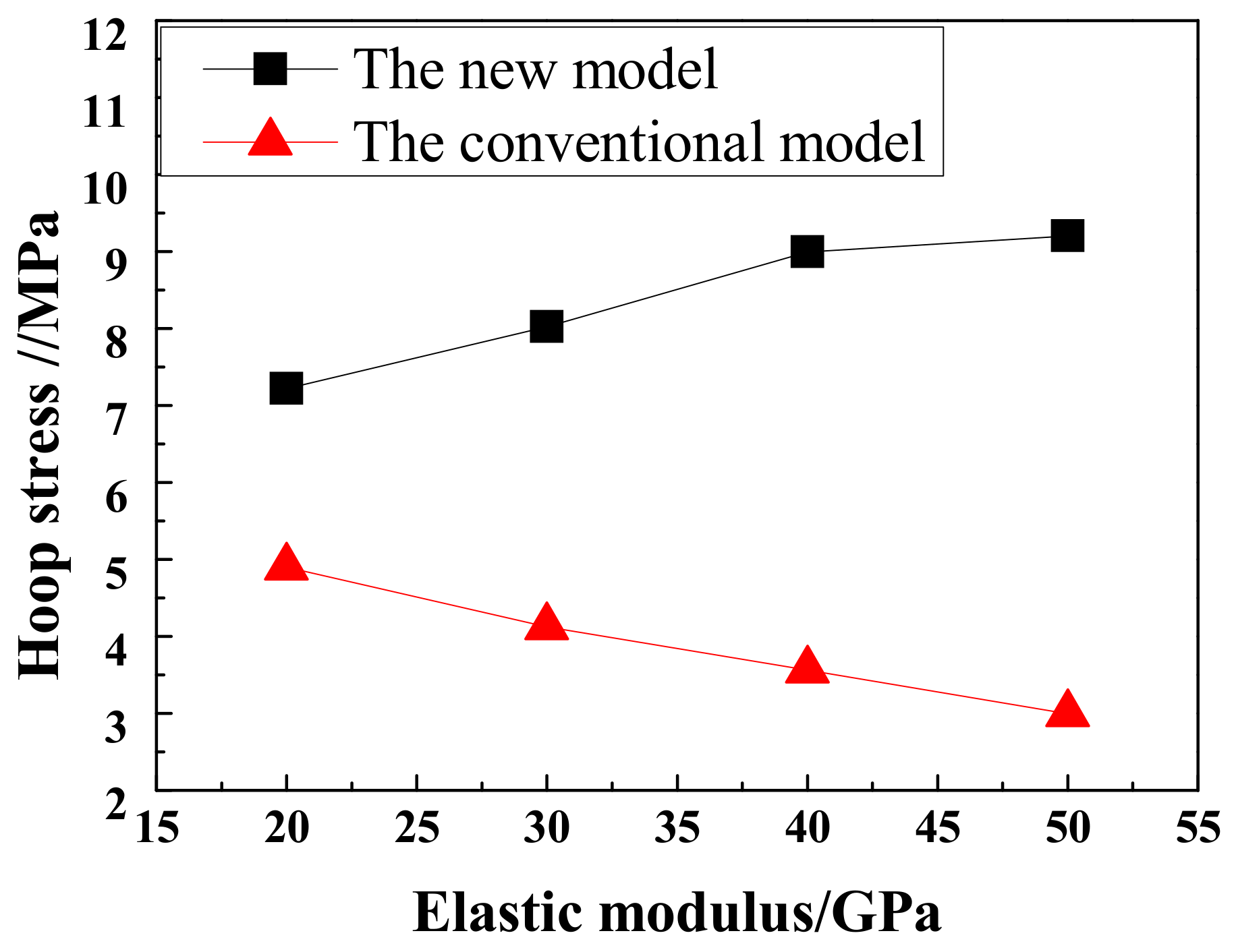
The range of the cement elastic modulus used in Weiyuan block is 9.4–50 GPa [16,17]. Figure 13 presents the influence of the cement sheath elastic modulus on the hoop stress of the cement sheath. For the conventional model, the hoop stress of the cement sheath increased slowly with its increasing elastic modulus, and the overall change is not obvious. As for the new model, it can be clearly observed that the increase of cement sheath elastic modulus turned the hoop stress of the cement sheath from compressive to tensile. Thus, to determine the appropriate values of the cement elastic modulus in the field situations can markedly improve its downhole stress state of the cement sheath, and reduce the risk of the cement sheath failure.
4. Conclusions
To accurately predict the stress state and variation regularities of cement sheath during the multi-stage fracturing process of shale gas wells, a finite element model of the casing-cement sheath-formation assembly is built in this paper under formation anisotropy conditions based on the staged finite element method to analyze the effects of operation parameters and formation property variations on the stress state of cement sheaths. Afterwards, the calculation results are compared with the previous model. This paper draws the following conclusions:
- (1)
- The internal casing pressure is rather high during fracturing, and the inner wall of cement sheath is subjected to tensile stress. Volume fracturing will greatly change the temperature of casing and cement sheath. The increase of fracturing fluid temperature and control of flow rate in the fracturing process can reduce the downhole temperature difference, which is conducive to reducing the temperature stress effect on the hoop stress of cement sheaths for shale gas wells.
- (2)
- Substantial formation of fractures and fracturing fluid infiltration into the formation during the multi-stage fracturing process will lead to changes in the geostress, pore pressure and formation property around the wellbore. The risk of cement sheath tensile failure is increased in the stress deficit zones and the pore pressure build-up zones. With the decreasing mechanical properties of formation in the fracturing process, the risk of cement sheath tensile failure is reduced to some extent.
- (3)
- The elastic modulus of cement sheath has a great effect on its structure. In the site construction, an appropriate reduction of cement sheath elastic modulus and optimization of cementing quality can markedly reduce the risk of cement sheath tensile failure.
Acknowledgments
This research was financially supported by the National Natural Science Funds of China (51674272), the Key Program of National Natural Science Foundation of China (U1762211), the National Natural Science Funds (51674272) and National Science and Technology Major Project(2017ZX05009).
Author Contributions
All the authors conceived and designed the study. Mingtao Fan performed the simulation for case studies and wrote the paper; Jun Li and Gonghui Liu reviewed and edited the manuscript.
Conflicts of Interest
The authors declare that there is no conflict of interests regarding the publication of this paper.
Nomenclature
| D−1 | Elastic flexibility matrix |
| Ec | Elastic modulus of the cement, GPa |
| Ef | Elastic modulus of formation, GPa |
| Es | Elastic modulus of casing, GPa |
| p | Horizontal stress, MPa |
| pci | Initial stress of cement sheath, MPa |
| pmi | Internal casing pressure, MPa |
| pi | Hydrostatic pressure during cementing, MPa |
| q | Vertical stress, MPa |
| rf | Outer radius of formation, m |
| rs1 | Original inner radius of casing, m |
| rs2 | Original outer radius of casing, m |
| rs2’ | Outer radius of deformation casing, m |
| rw0 | Inner radius of wellbore after inner rock excavated, m |
| rw1 | Inner radius of wellbore after cementing, m |
| rwc | Radius of wellbore during drilling, m |
| ucl | Inner radius of cement sheath, m |
| uc2 | Outer radius of cement sheath, m |
| ur | Radius of wellbore during drilling, m |
| us | Outer radius variation of casing, m |
| us2 | Outer radius of casing, m |
| uw1 | Radius of wellbore, m |
| vc | Poisson’s ratio of the cement |
| vf | Poisson’s ratio of formation |
| vs | Poisson’s ratio of casing |
| Greek symbols | |
| σ’ | Stress tensor |
| σh | Minimum horizontal principal stress, MPa |
| σv | Overburden pressure, MPa |
| ε’ | Solid strain tensor |
| α | constant term |
| β | constant term |
References
- Tian, Z.; Shi, L.; Qiao, L. Research of and Countermeasure for Wellbore Integrity of Shale Gas Horizontal Well. Nat. Gas Ind. 2015, 35, 70–76. [Google Scholar]
- Jackson, P.B.; Murphey, C.E. Effect of Casing Pressure on Gas Flow through a Sheath of Set Cement. In Proceedings of the SPE Drilling Conference, Amsterdam, The Netherlands, 22–25 February 1993. SPE 25698. [Google Scholar]
- Goodwin, K.J.; Crook, R.J. Cement Sheath Stress Failure. SPE Drill. Eng. 1992, 7, 291–296. [Google Scholar] [CrossRef]
- Albawi, A.; De Andrade, J.; Torsæter, M.; Stroisz, A.; Vrålstad, T. Experimental Set-Up for Testing Cement Sheath Integrity. In Proceedings of the OTC Arctic Technology Conference, Houston, TX, USA, 10–12 February 2014. OTC-24587. [Google Scholar]
- McDaniel, J.; Watters, L.; Shadravan, A. Cement Sheath Durability: Increasing Cement Sheath Integrity to Reduce Gas Migration in the Marcellus Shale Play. In Proceedings of the SPE Hydraulic Fracturing Technology Conference, Woodlands, TX, USA, 4–6 February 2014. SPE 168650. [Google Scholar]
- Bui, B.T.; Tutuncu, A.N. Modeling the Failure of Cement Sheath in Anisotropic Stress Field. In Proceedings of the SPE Unconventional Resources Conference, Calgary, AB, Canada, 5–7 November 2013. SPE-167178. [Google Scholar]
- Dai, Q. Analysis of Production Casing Damage Reasons during Testing and Completion of Shale Gas Well. Drill. Prod. Technol. 2015, 38, 22–25. [Google Scholar]
- Sugden, C.; Ring, G.A.; Chambers, M.R.; Suryanarayana, P.V. Special Considerations in the Design Optimization of High Rate, Multistage Fractured Shale Wells. In Proceedings of the SPE Drilling Conference and Exhibition, San Diego, CA, USA, 6–8 March 2012. SPE 151470. [Google Scholar]
- Batugin, S.A.; Nirenburg, R.K. Approximate Relation between the Elastic Constants of Anisotropic Rocks and the Anisotropy Parameters. J. Min. Sci. 1972, 8, 5–9. [Google Scholar] [CrossRef]
- Yin, Y.; Chen, C.; Li, P. Theoretical Solutions of Stress Distribution in Casing-cement and Stratum System. Chin. J. Theor. Appl. Mech. 2006, 38, 835–842. [Google Scholar]
- Li, M.; Liu, G.; Li, J.; Zhang, T.; He, M. Thermal performance analysis of drilling horizontal wells in high temperature formations. Appl. Therm. Eng. 2015, 78, 217–227. [Google Scholar] [CrossRef]
- Liu, Z.; Li, H.; Liu, K.; Yu, H.; Cheng, K. Design of high-performance water-in-glass evacuated tube solar water heaters by a high-throughput screening based on machine learning: A combined modeling and experimental study. Sol. Energy 2017, 142, 61–67. [Google Scholar] [CrossRef]
- Liu, Z.; Xu, W.; Zhai, X.; Qian, C.; Chen, X. Feasibility and performance study of the hybrid ground-source heat pump system for one office building in Chinese heating dominated areas. Renew. Energy 2017, 101, 1131–1140. [Google Scholar] [CrossRef]
- Lian, Z.; Yu, H.; Lin, T.; Guo, J. A study on casing deformation failure during multi-stage hydraulic fracturing for the stimulated reservoir volume of horizontal shale wells. J. Nat. Gas Sci. Eng. 2015, 23, 538–546. [Google Scholar] [CrossRef]
- Tian, F. Elasticity Modulus and Fracture Density in the Rocks with Crevices. Acta Geol. Sin. 2007, 81, 1338–1344. [Google Scholar]
- Tao, Q.; Ding, S.; Liu, W. Study on cementing slurry system in shale gas well. China Pet. Mach. 2011, 39, 17–19. [Google Scholar]
- Tao, Q.; Chen, X. Causal analysis and countermeasures on B sustained casing pressure of shale-gas horizontal wells in the Sichuan Basin. Oil Drill. Prod. Technol. 2017, 39, 588–593. [Google Scholar]
Figure 1.
Sketch of the traditional model.

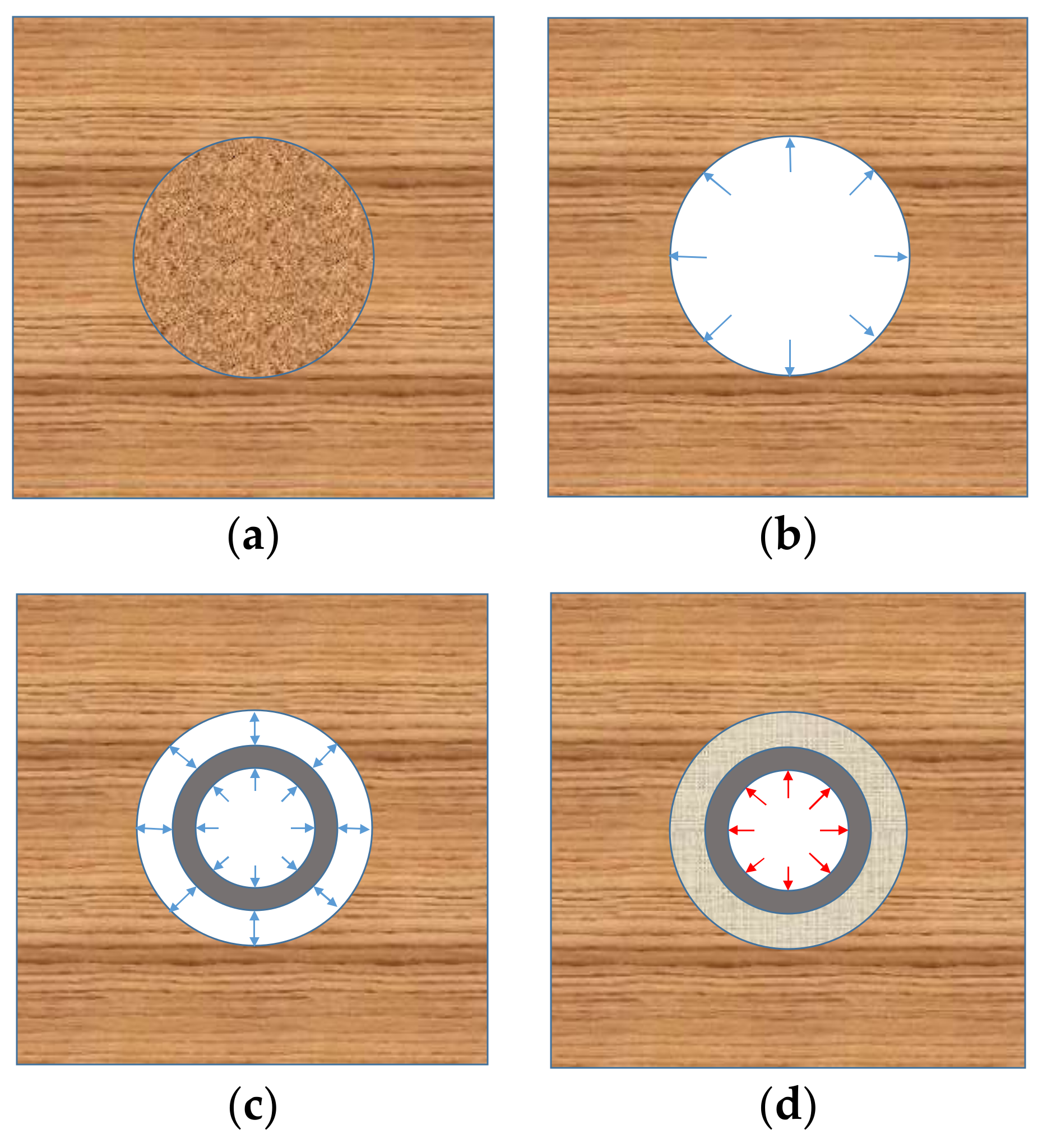
Figure 2.
Sketch of the step by step method. (a) Initial state; (b) drilling; (c) cementing; (d) hydraulic fracturing.
Figure 2.
Sketch of the step by step method. (a) Initial state; (b) drilling; (c) cementing; (d) hydraulic fracturing.

Figure 3.
The coordinate system of shale.
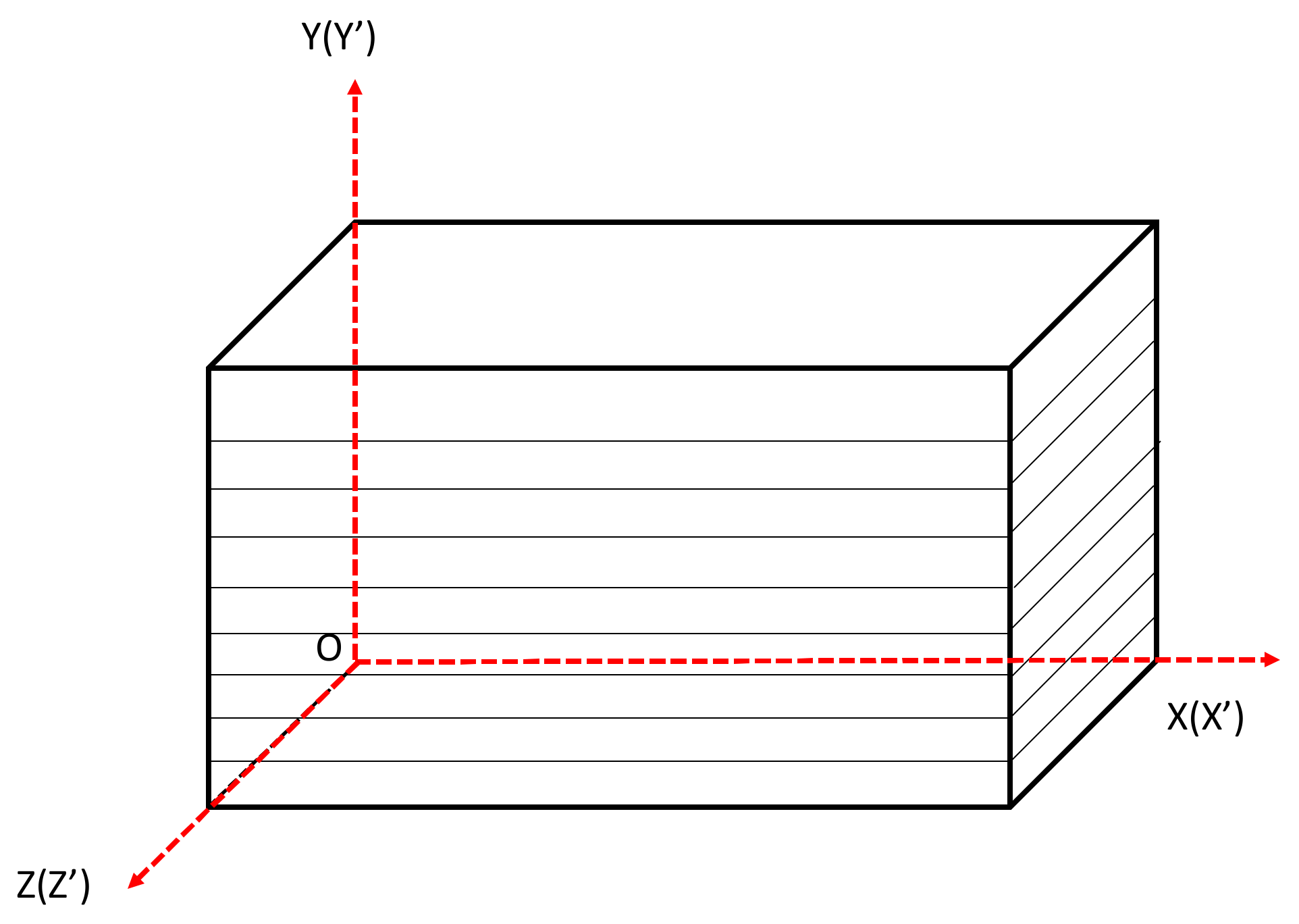
Figure 4.
Curve comparison of calculation result. (A) Drilling: The inner pressure is 20 MP; geo-stress is 30 MPa; (B) Cementing: The inner pressure is 20 MPa; (C) Hydraulic fracturing: The pump pressure is 90 MPa.
Figure 4.
Curve comparison of calculation result. (A) Drilling: The inner pressure is 20 MP; geo-stress is 30 MPa; (B) Cementing: The inner pressure is 20 MPa; (C) Hydraulic fracturing: The pump pressure is 90 MPa.


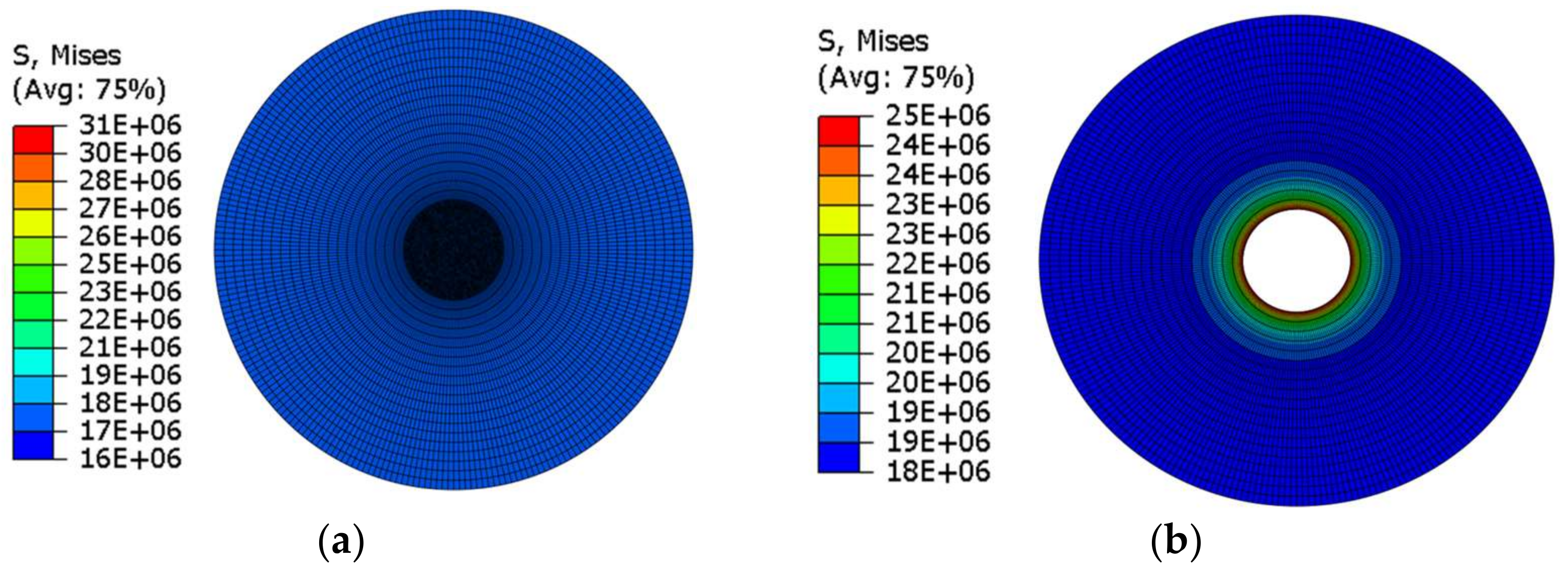
Figure 5.
Schematic diagrams of the staged FEM analysis (a) Balancing stress field; (b) Drilling; (c) Inserting casing; (d) Cementing; (e) Hydraulic fracturing.
Figure 5.
Schematic diagrams of the staged FEM analysis (a) Balancing stress field; (b) Drilling; (c) Inserting casing; (d) Cementing; (e) Hydraulic fracturing.


Figure 6.
The temperature variation of cement sheath.

Figure 7.
Hoop Stress of cement sheath vs. Temperature.
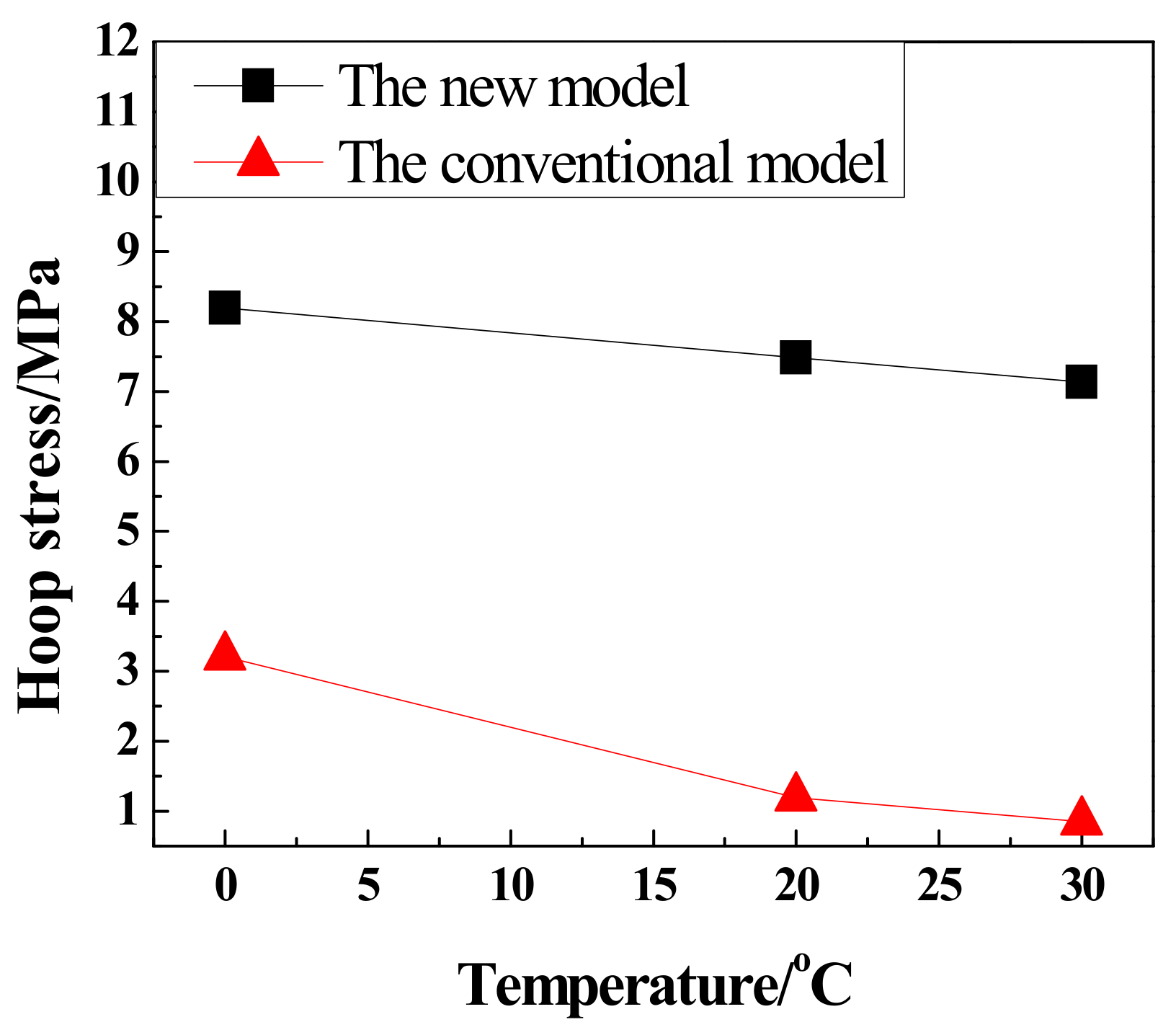
Figure 8.
Hoop stress of cement sheath vs. inner pressure.
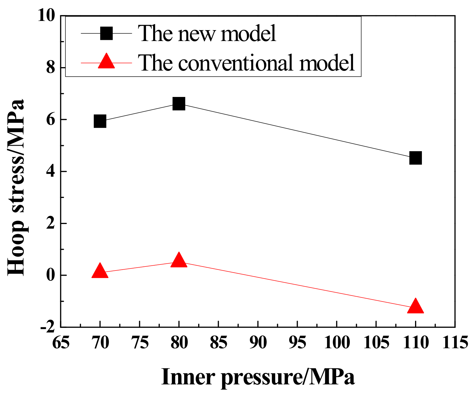
Figure 9.
Hoop stress of cement sheath vs. in-situ stress.

Figure 10.
Hoop stress of cement sheath vs. pore pressure.
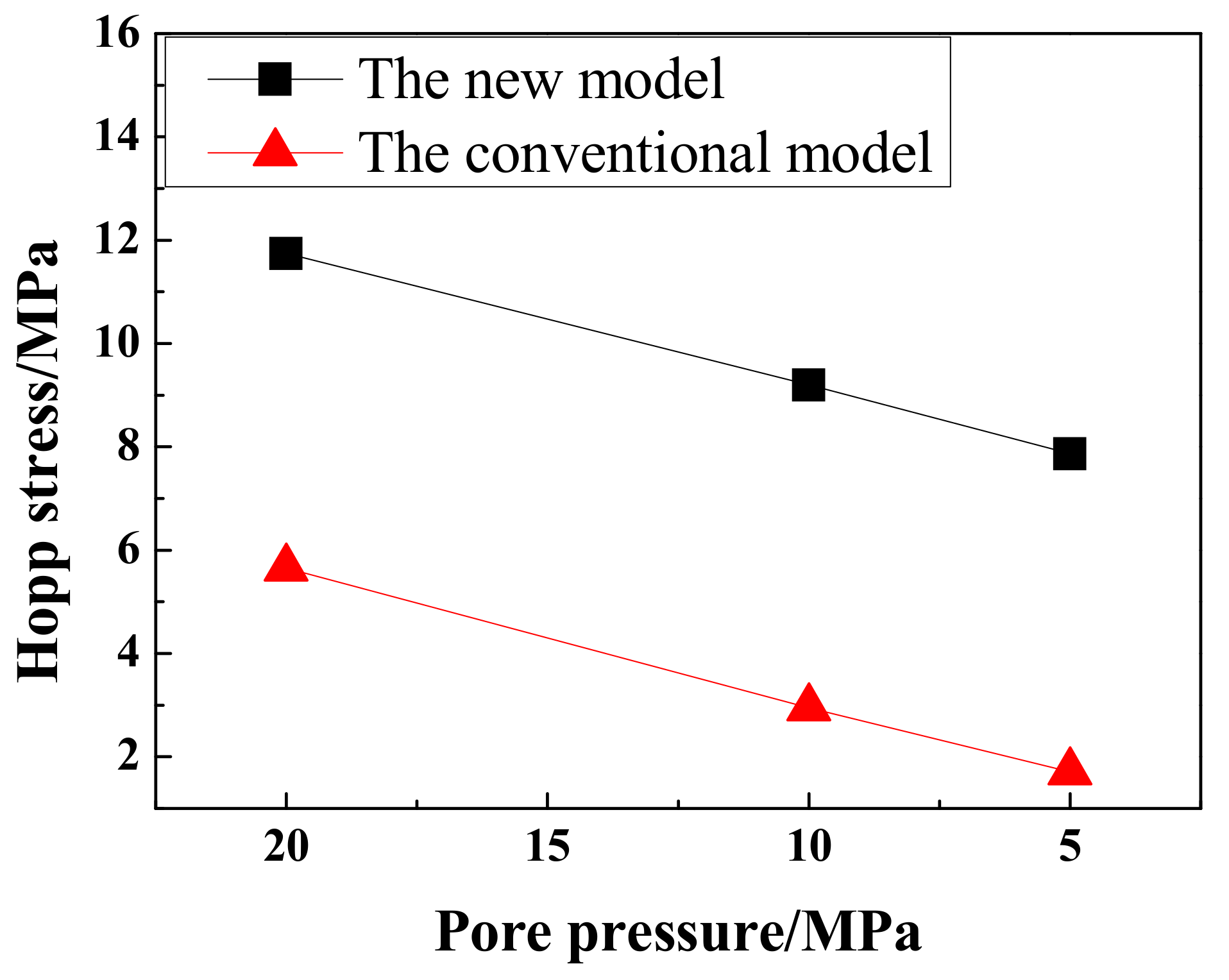
Figure 11.
Hoop stress of cement sheath vs. anisotropy index (k).

Figure 12.
Hoop stress of cement sheath vs. rock elastic modulus.

Figure 13.
Hoop stress of cement sheath vs. cement sheath elastic modulus.


Table 1.
Geometry parameters and material characteristics of the model.
| Medium | OD/ | ID/ | Young’s Modulus/ | Poisson’s Ratio | Internal Friction Angle/° | Cohesion/ |
|---|---|---|---|---|---|---|
| Casing | 139.7 | 131.98 | 210 | 0.3 | - | - |
| Cement sheath | 215.9 | 139.7 | 9 | 0.15 | 17.1 | 21.6 |
| Formation | 1270 | - | : 20 : 17 | : 0.20 : 0.18 | 30 | 59.3 |
Table 2.
Thermodynamic parameters of the model.
| Medium | Density/(kg·m−3) | Expansion Coefficient/°C−1 | Specific Heat Capacity/ | Thermal Conductivity Coefficient/ |
|---|---|---|---|---|
| Casing | 7800 | 1.22 × 10⁻⁵ | 460 | 45 |
| Cement sheath | 1800 | 1.05 × 10⁻⁵ | 865 | 0.9 |
| Formation | 2300 | 1.03 × 10⁻⁵ | 896 | 2.2 |
© 2018 by the authors. Licensee MDPI, Basel, Switzerland. This article is an open access article distributed under the terms and conditions of the Creative Commons Attribution (CC BY) license (http://creativecommons.org/licenses/by/4.0/).
Share and Cite
MDPI and ACS Style
Fan, M.; Li, J.; Liu, G. New Method to Analyse the Cement Sheath Integrity During the Volume Fracturing of Shale Gas. Energies 2018, 11, 750. https://doi.org/10.3390/en11040750
AMA Style
Fan M, Li J, Liu G. New Method to Analyse the Cement Sheath Integrity During the Volume Fracturing of Shale Gas. Energies. 2018; 11(4):750. https://doi.org/10.3390/en11040750
Chicago/Turabian StyleFan, Mingtao, Jun Li, and Gonghui Liu. 2018. "New Method to Analyse the Cement Sheath Integrity During the Volume Fracturing of Shale Gas" Energies 11, no. 4: 750. https://doi.org/10.3390/en11040750
Note that from the first issue of 2016, this journal uses article numbers instead of page numbers. See further details here.