1. Introduction
Doubly fed induction generators (DFIGs) have become the mainstream of wind turbines in the past several decades [
1]. The safety of power system has attracted more attention due to the increasing use of DFIGs. The wind turbines are required to connect to the grid and provide reactive power under grid fault [
2]. However, the reactive power of DFIGs will affect the transient stability of power system.
Some studies have investigated the effects of the DFIG on the rotor angle characteristics of the synchronous generator (SG) [
3,
4,
5,
6]. However, the DFIG was considered as an active power source without inertia and the lack of inertia could affect system rotor angle stability [
4]. Actually, the reactive power of the DFIG can also affect the rotor angle stability [
5,
6]. However, the results were obtained by simulations rather than theoretical analysis.
Utilizing the reactive power of the DFIG is one of feasible solutions to improve system rotor angle stability. A decoupled-DFIG strategy was presented in [
7] that the active power of stator and reactive power of the grid-side converter (GSC) could be improved to enhance the stability performance under the induction generator mode. A flux magnitude and angle control scheme was proposed in [
8] to improve system stability. A coordinated control strategy of wind-thermal hybrid AC/DC power system was proposed in [
9] in order to improve the system stability. However, the results were not accurate since the power constraints of DFIG were not considered.
To guarantee the safe operation of DFIG under grid fault, overcurrent and overspeed are supposed to be avoided. The constraints of converter current and rotor speed on transient power determine the contribution to rotor angle stability of power system. However, the related studies have focused on the restriction of maximum converter current on reactive power [
10,
11,
12]. Besides, the reactive power of DFIG is also limited by active power, which is determined by rotor speed. Though the reactive power capacity considering the constraint of rotor speed was discussed in [
13], the relationship between the rotor speed and active power may be not accurate under the grid fault. It was advocated in [
11] that the reactive power of DFIG was restricted by converter current as well as rotor speed. But, reactive power capacity was discussed under steady state instead of that voltage dips.
The mechanical power is reduced gradually by the pitch control under the grid fault [
14]. In contrast, the active power falls rapidly because of the voltage dip. The transient active power needs to be adjusted to balance the mechanical power to avoid overspeed. Hence the reactive power is inevitably restricted. It is necessary to consider the coordination between active and reactive power for both safe operation of the DFIG and system transient stability enhancement.
This study aims to obtain the effect of DFIG on system rotor angle characteristics and propose a rotor angle stability enhancement control method using the DFIG. To achieve the goals, the contribution of DFIG to the acceleration area of SG is analyzed based on equal-area criterion. Additionally, the power constraints of DFIG brought by converter current and rotor speed is considered innovatively. The power constraints are obtained by power equations in emergency pitch control. The reminder after the introduction is organized, as follows: The math model and transient power expressions of DFIG are analyzed in
Section 2. The effect of DFIG on the rotor angle characteristics of SG is discussed in
Section 3. Reactive power limits of the rotor-side converter (RSC) and GSC are deduced, respectively, in
Section 4 and
Section 5. The rotor angle stability enhancement control method of DFIG is presented in
Section 6. Four digital simulation cases are studied in
Section 7 to verify the effectiveness of proposed method. Conclusions are drawn in
Section 8.
2. Transient Power of DFIG
The rotor of DFIG is connected to the grid through a back-to-back converter. Variable-speed constant-frequency output is obtained through the control of rotor-side converter (RSC). During the grid fault, rotor speed will change due to the imbalance of mechanical power and electro-magnetic power. Transient components of currents and voltages can be neglected in an electromechanical timescale [
15]. Voltage and flux vector equations of the stator and rotor are described, as follows:
where
,
and
are the voltage vector, current vector, and flux linkage vector, respectively.
The low voltage ride-through (LVRT) control is activated under the grid fault. The outer-loop controller of the RSC is locked, and the references of the inner loop are set directly. The inner-loop controller is usually designed as a typical type-I system, which denotes a large bandwidth and fast response [
16]. Therefore, rotor currents track the references in the electromechanical process effectively. The stator current is derived from the equivalent circuit, as shown as follows:
where
and
are the excitation reactance and stator reactance, respectively.
is the rotor current reference vector.
The
d-axis of synchronous rotating reference frame is oriented to the stator voltage when the voltage-oriented control is employed. The stator power is expressed, as follows:
where
and
are the
d- and
q-axis references of the rotor current, respectively, and
is the amplitude of the stator voltage.
The GSC usually operates in unity power factor mode and supplies reactive power under the grid fault. When the
d-axis is oriented to the grid voltage similar to the RSC, the transient power of GSC can be expressed as
where
and
are the
d- and
q-axis references of the GSC, respectively.
By neglecting the losses in the stator and rotor, the rotor-side active power is obtained as [
11]
The rotor-side active power flows through the GSC, so
. Combining Equations (4) and (5) yields the active current of the GSC, as shown as follows:
where
is the slip.
The total transient active and reactive currents of DFIG is expressed as
where
and
are active and reactive currents, respectively:
The transient currents of DFIG can be regulated by the references to support the grid voltage and hence affect the rotor angle characteristics of SG.
3. Effect on Rotor Angle Characteristics
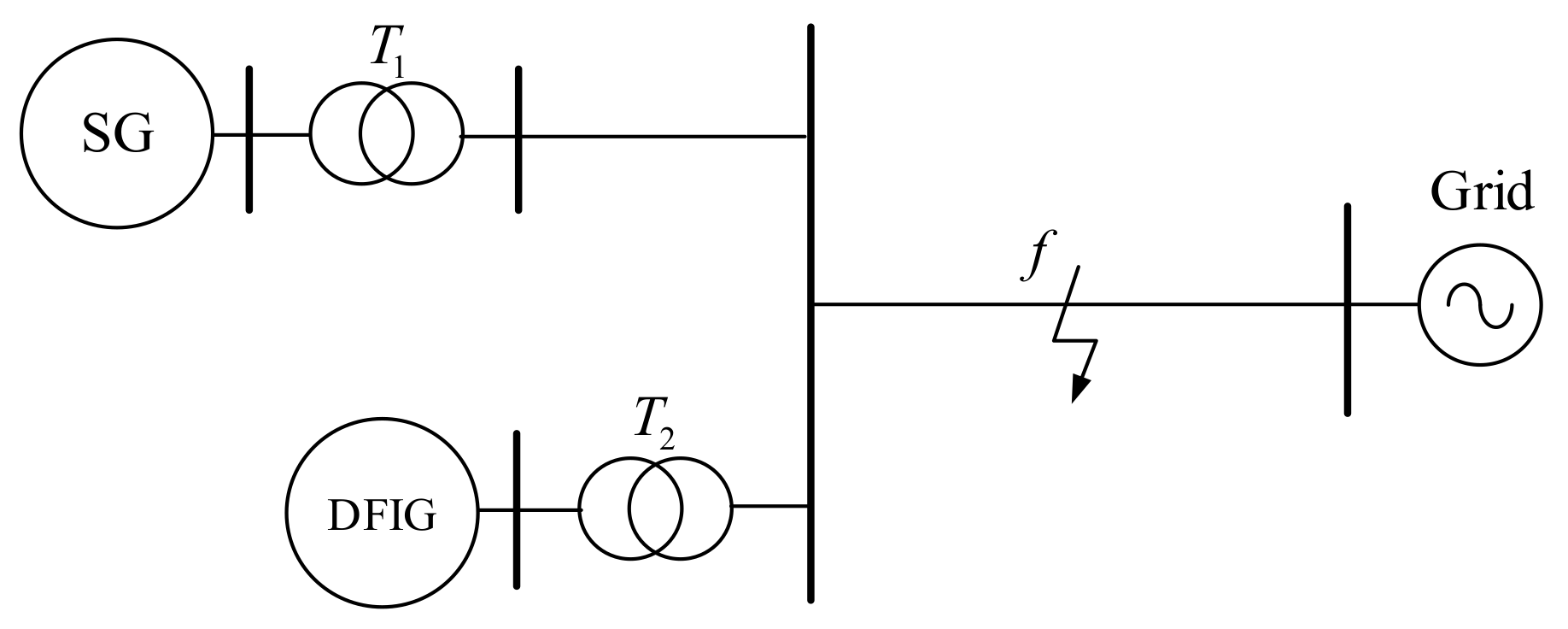
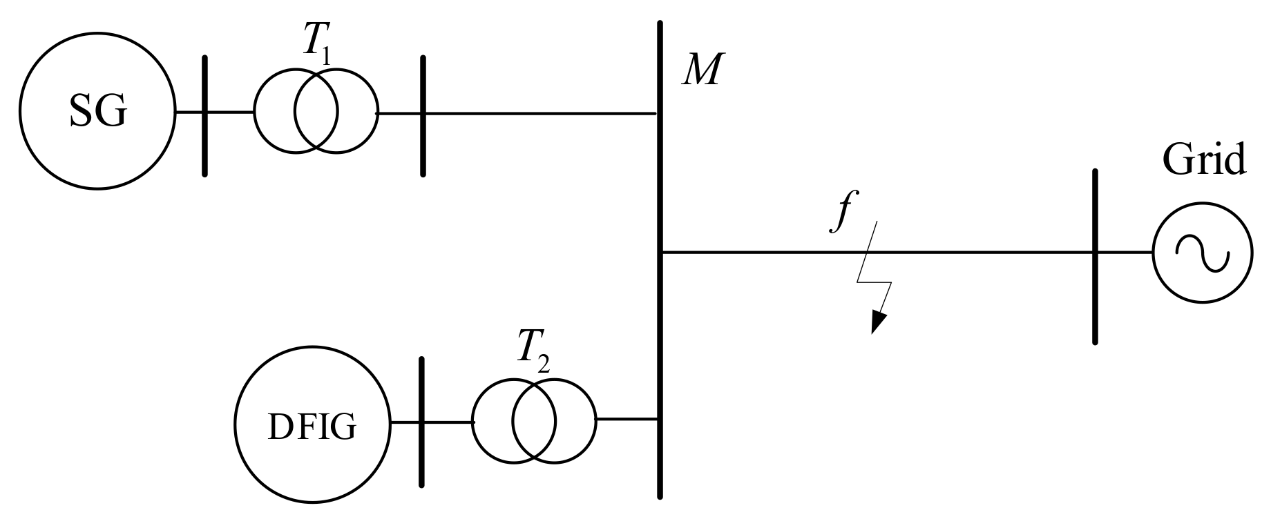
A double-machine system consisting of a DFIG and a SG is shown in
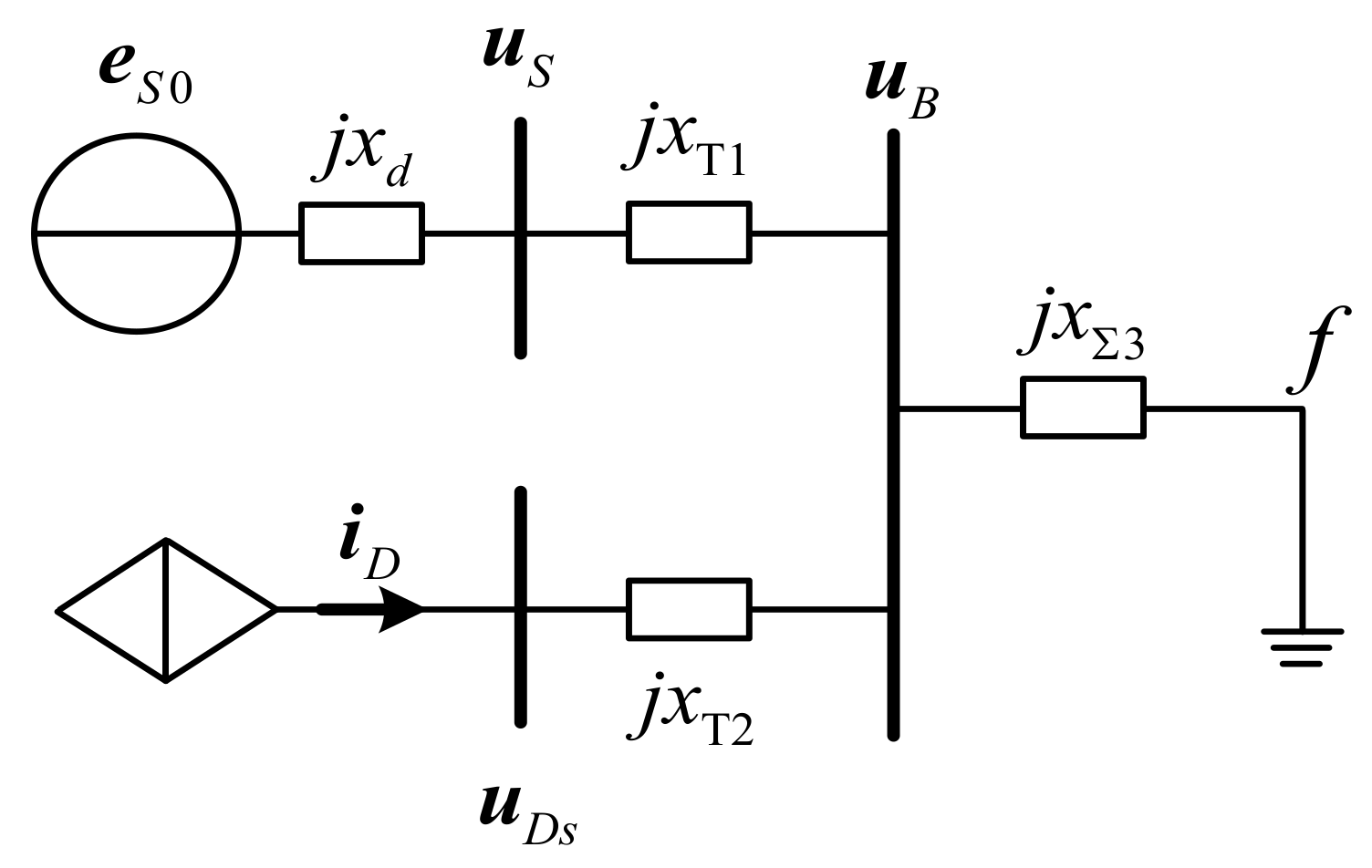
Figure 1. When a metallic fault occurs at point
f, an equivalent circuit of the system can be built, as shown in
Figure 2.
is the no-load electromotive force of SG in the synchronous reference frame of DFIG
is the amplitude, and
is the angle between the synchronous reference frame
q-axis of SG and that of DFIG.
From the derivation above, the DFIG can be equivalent to a controlled current source. When the active and reactive power of DFIG are positive,
is positive whereas
is negative.
is the synchronous reactance of SG, and
,
are the equivalent reactance of SG and DFIG transformers, respectively.
is the reactance from the SG to bus B, and
is the reactance from bus B to point
f. According to the equivalent circuit, the voltages of bus B and the DFIG stator can be solved, as follows:
where
,
, and
.
The d-axis can be accurately oriented to stator voltage, so that
only comprises the d-axis component. Thus, the image part of Equation (10) is zero. According to Equations (9) and (10), the amplitude of bus B can be derived, as follows:
Using the partial derivative of Equation (11) to
and yields
As is positive, and is negative, Equation (12) indicates that the voltage amplitude of bus B increases with the decrease of DFIG active power and increases along with the reactive power.
The rotor angle characteristic of SG can be described, as follows:
where
is the active power of SG, and
is the rotor angle.
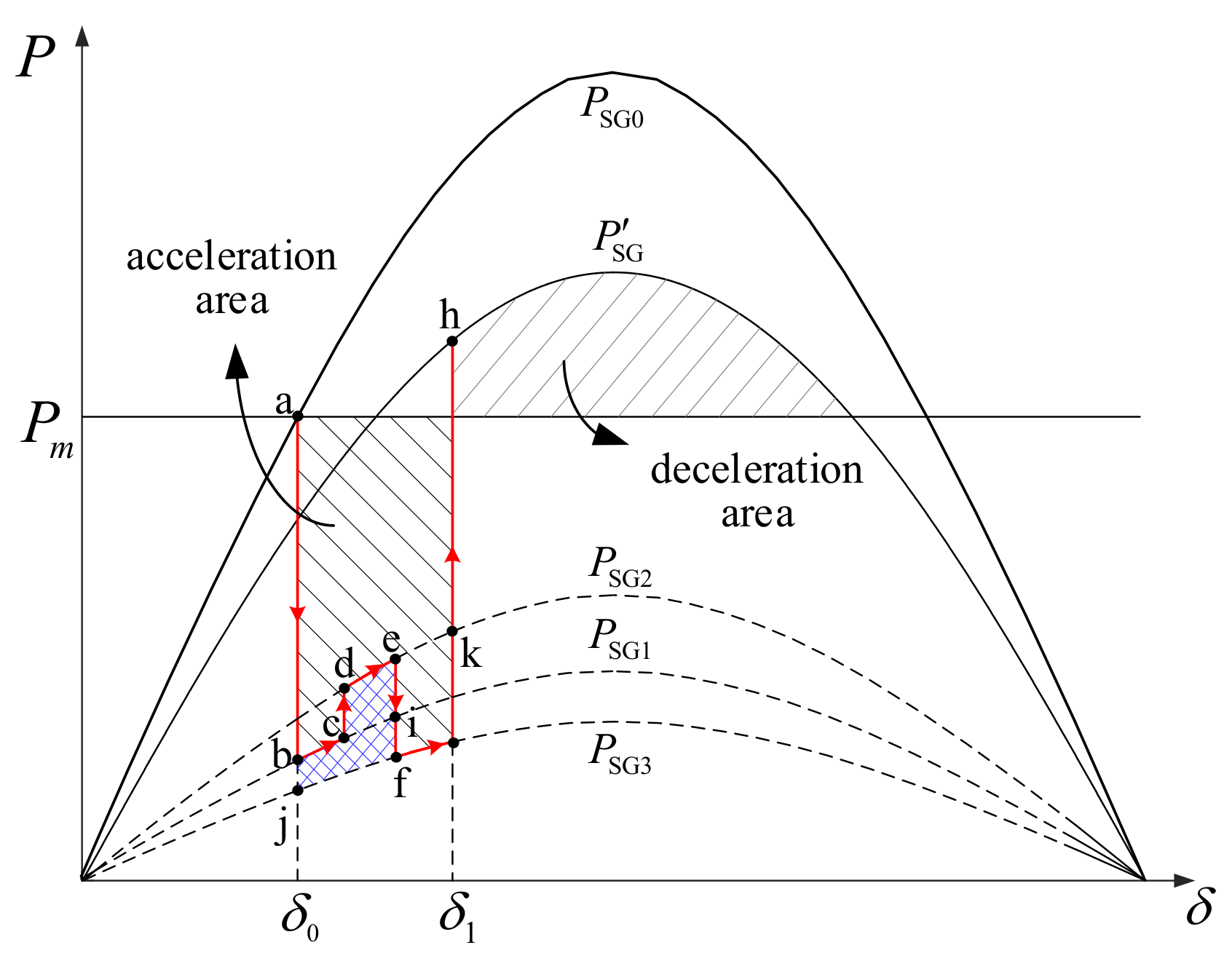
The rotor angle characteristics of SG with the influence of DFIG is shown in
Figure 3. The active power of SG decreases after the grid fault. With the transient control of DFIG working, the operation point of SG moves from point
a on curve
to point
b on curve
. As the mechanical power exceeds the active power, the SG rotor accelerates. The DFIG reduces the active power and enlarges the reactive power, which raises the voltage amplitude of bus B. Therefore, the operation point of SG moves from point
c to point
d. If the DFIG disconnects from the grid because of overspeed at point
e, the reactive power support that is provided by the DFIG disappears. It results in the decrease in the voltage amplitude of bus B and active power of SG. The operation point of SG moves to point
f on
. Finally, the grid fault is cleared at point
g, and the operation point of SG moves to point
h on
.
In this entire process, the acceleration area of SG decreases by
(the blue area in
Figure 3) when compared with curve
without the influence of DFIG. The acceleration area of SG decreases by
as compared with curve
due to more reactive power being contributed by the DFIG at point
c. If the DFIG does not overspeed throughout, then the operation point of SG will move from point
e to point
k instead of point
f. Therefore, the acceleration area of SG decreases by
when compared with present operation path. According to the analysis above, the DFIG should not overspeed and supply more reactive power for the good of system rotor angle stability. However, the reactive power of DFIG is limited by the maximum converter current and the rotor speed.
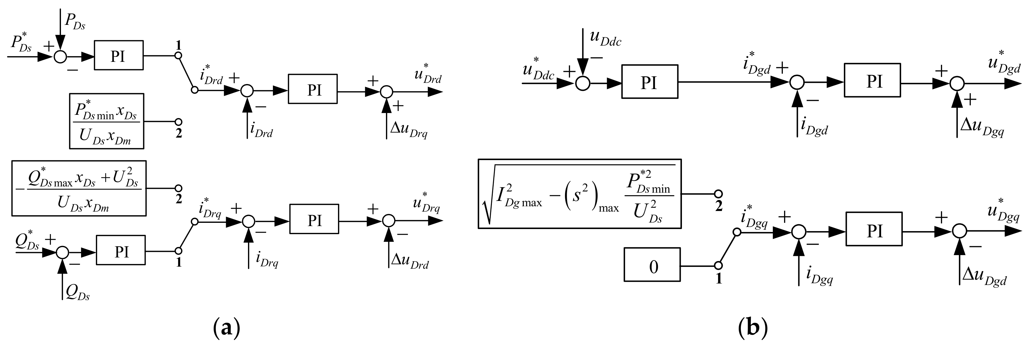
6. System Rotor Angle Stability Enhancement Control Method
A system rotor angle stability enhancement control method using the DFIG while considering its reactive power constraints is proposed as shown in
Figure 4. The double closed-loop structure is utilized in the RSC to control the active and reactive power in normal operation. The references of the inner-loop controller are determined by the outer-loop controller. The outer loop of the GSC controls the DC bus voltage. After the grid fault, the proposed control and emergency pitch control are activated. The initial rotor speed that makes
exactly equal to zero is defined as the critical rotor speed:
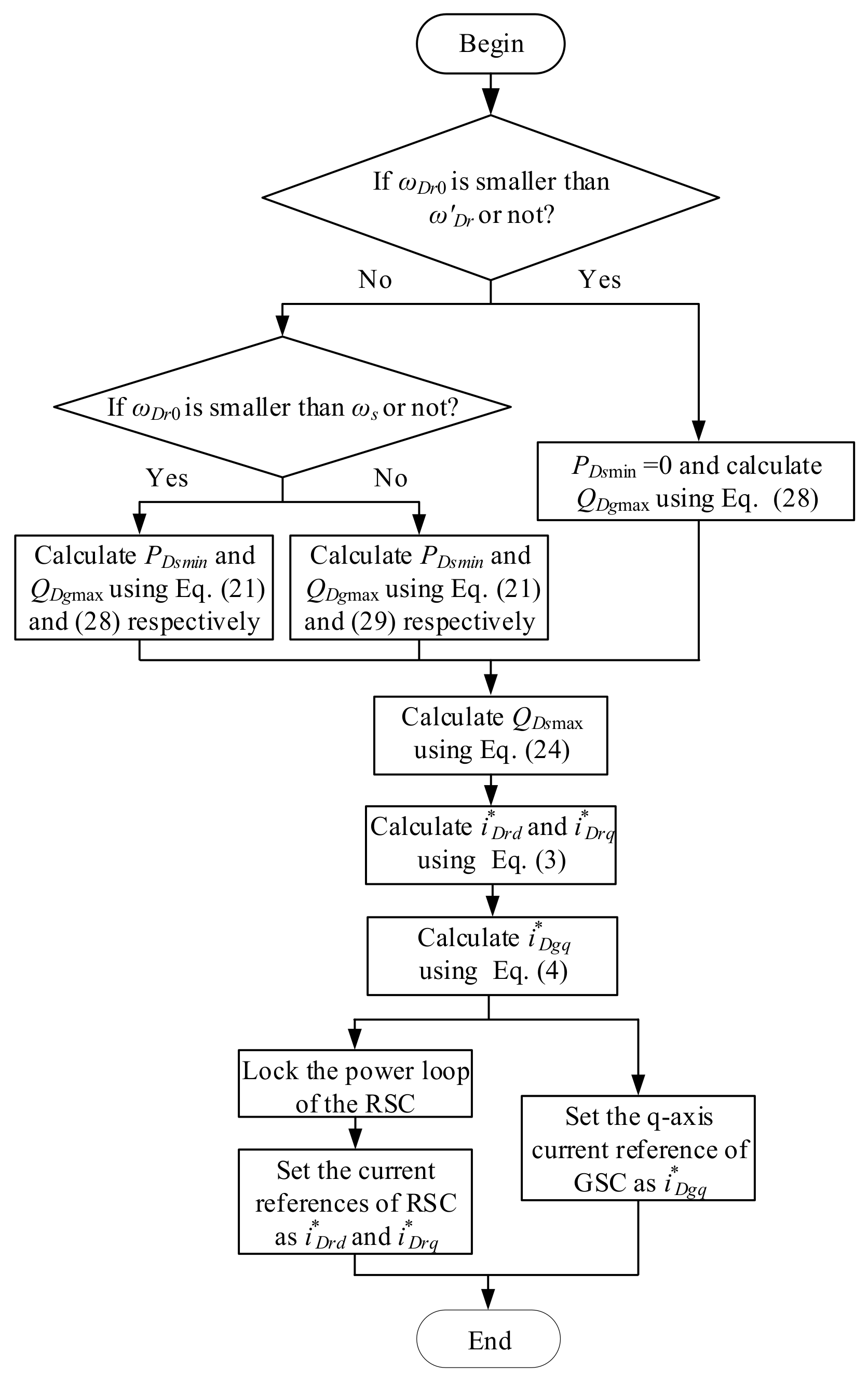
The control flowchart is shown in
Figure 5. First, if the initial speed
is greater than
, then
is calculated using Equation (21) and
is calculated using Equation (29). If
is between
and
,
and
are calculated using Equations (21) and (28) respectively. If
is smaller than
,
is directly set as zero whereas
is calculated using Equation (28). According to
and the power that is calculated above,
and
can be calculated using Equation (3), and
can be calculated using Equation (4). Then, the outer loop of the RSC is locked, and the inner loop of the RSC and GSC switches from steady-state control to the proposed control.
7. Case Studies
The simulation system that is shown in
Figure 6 is established in MATLAB/Simulink. The DFIG wind farm is equaled as a single DFIG. The SG connects to the bus M through a 30-km line, whereas the DFIG connects to bus M directly. Bus M connects to the grid through a 100-km line. The rated capacity of SG is 300 MVA, with initial output active power of 120 MW. The rated capacity of DFIG is 225 MVA, with a rated wind speed of 15 m/s. The rated rotor speed of the generator of DFIG is 1.20 p.u., whereas the threshold of overspeed protection is 1.30 p.u. The maximum currents of the RSC and GSC are 1.10 p.u. and 0.33 p.u., respectively. The maximum power point tracking control is adopted in normal operation. The proposed control and pitch control are conducted immediately after the grid fault. Moreover, the pitch angle is adjusted to 10°/s.
The DFIG operates in the rated condition at the initial time. A three-phase permanent short-circuit fault occurs at the point
f on the transmission line when t = 1 s. Four different simulation cases are shown in
Table 1 and are described as follows:
The stator voltage of DFIG declines to 0.70 p.u. in Cases 1 and 2 after the grid fault. The current reference values of the RSC at the q-axis in Cases 1 and 2 are the same, whereas those of the RSC and GSC at the d-axis are different. The stator voltage of DFIG decreases to 0.28 p.u. in Cases 3 and 4 after the grid fault. The current reference value at the q-axis of the RSC in Case 3 is set as 1.08 p.u. based on the existing grid code of China, and the current reference value at the d-axis is 0.19 p.u., accordingly. The proposed control in this study is utilized in Case 4, with the minimum active power of 0.24 p.u. and maximum speed of 1.29 p.u. Furthermore, the current reference values of the RSC at the d- and q-axes are 0.79 p.u. and 0.76 p.u., respectively, and that of the GSC at the q-axis is 0.25 p.u.
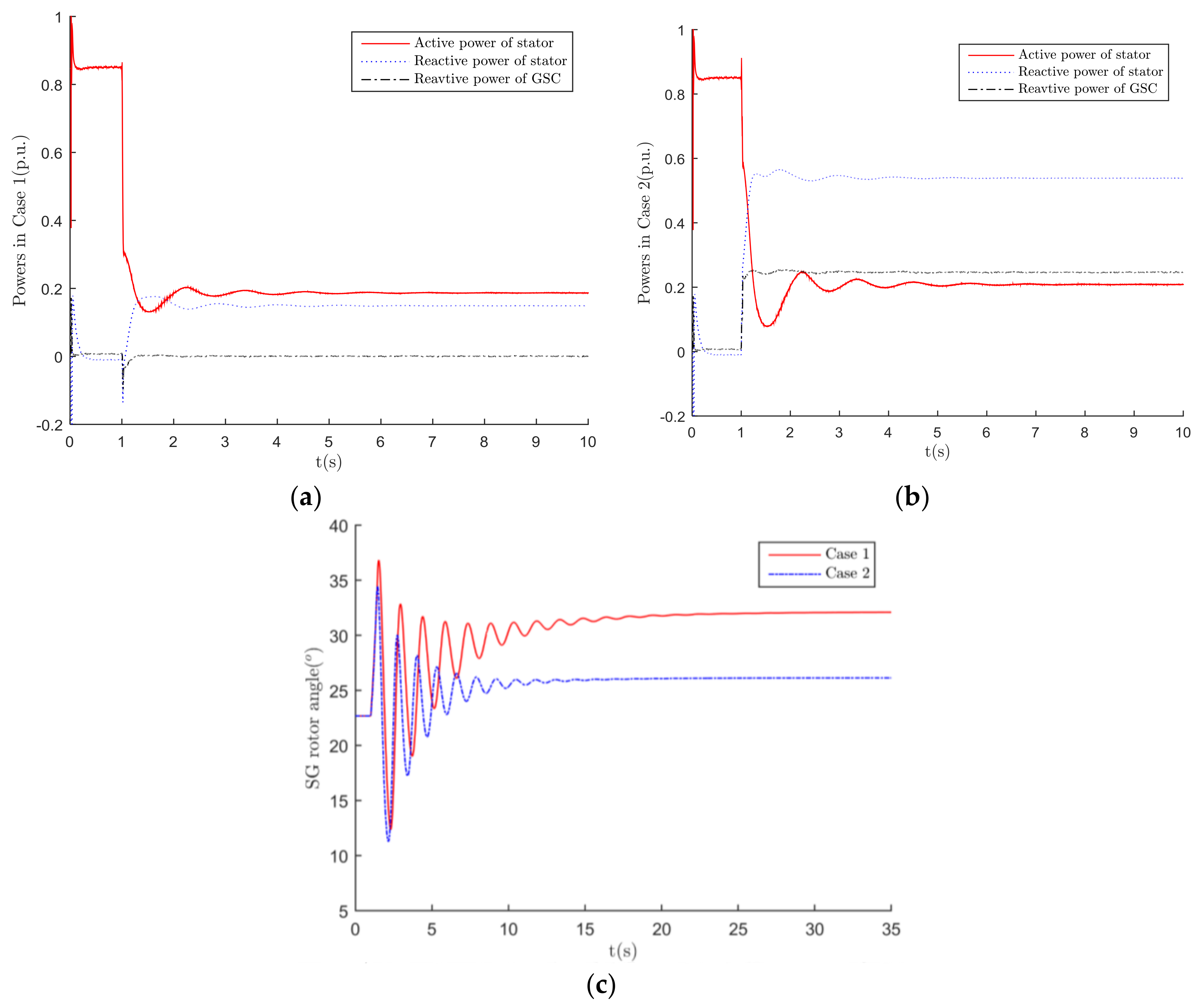
The transient power curves of the stator and GSC of DFIG in Cases 1 and 2 are shown in
Figure 7a,b, respectively. The active power of the stator is approximately 0.20 p.u. in both cases. The reactive power of the stator and that of GSC stabilize to about 0.15 p.u. and 0 p.u., respectively in Case 1. The reactive power of the stator and that of GSC stabilize to approximately 0.54 p.u. and 0.25 p.u., respectively, in Case 2.
Figure 7c shows the rotor angles of SG in Cases 1 and 2. The first three wings of the SG rotor angle in Case 1 are 36.82°, 32.86°, and 31.70°. Those in Case 2 are reduced by 2.34°, 2.84° and 3.53° respectively. The post-fault steady rotor angles in Cases 1 and 2 are 32.09° and 26.14°, respectively. Therefore, the rotor angle oscillation of SG decreases with the increase of DFIG reactive power, thereby improving the system rotor angle stability.
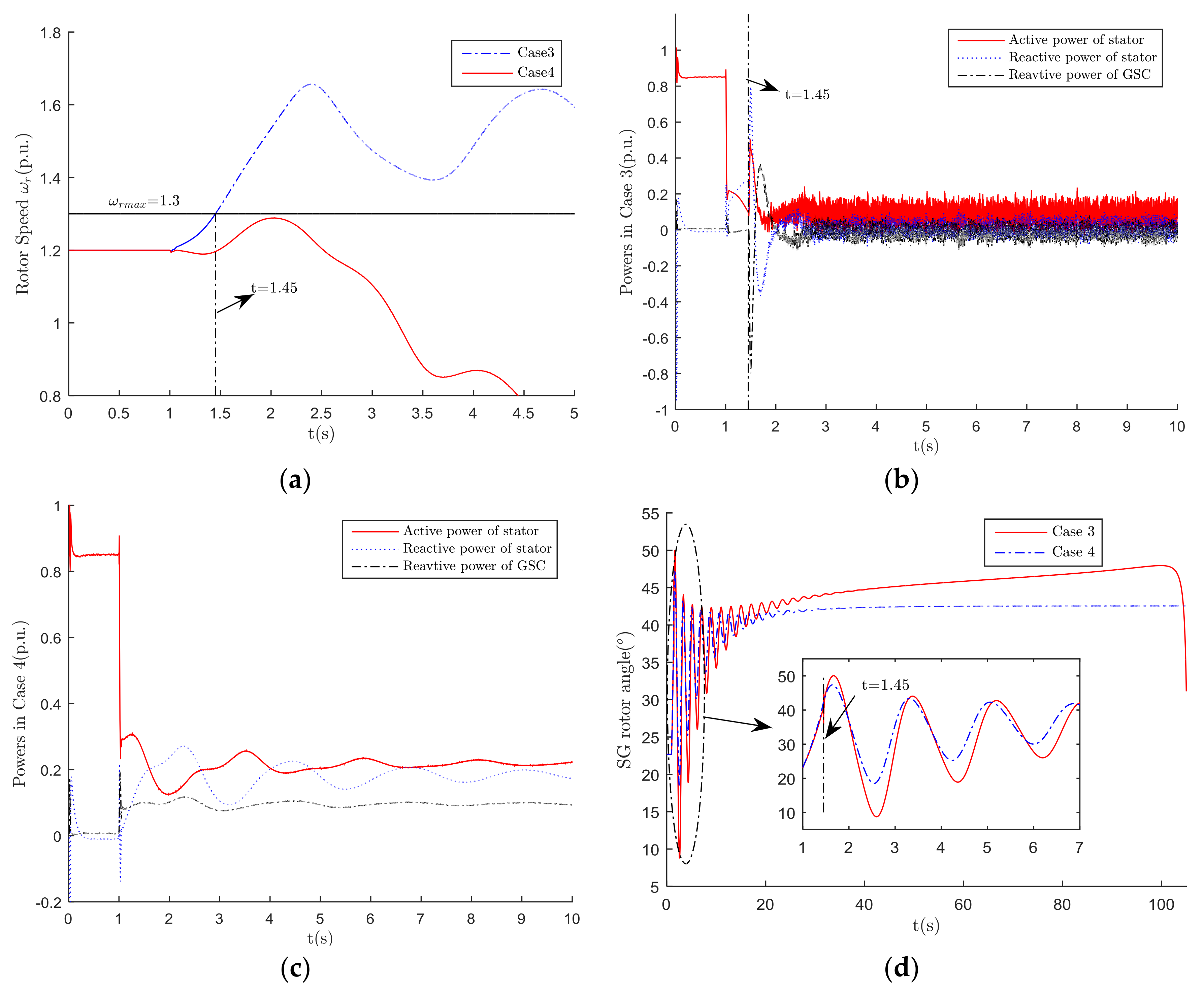
The rotor speed curves of DFIG in Cases 3 and 4 are shown in
Figure 8a. When the current reference of the RSC is set according to existing grid code, the active power of the stator is extremely small to balance the mechanical power, which results in the rotor speed exceeding 1.30 p.u. at 1.45 s. Although the reactive power of DFIG in Case 3 should be larger than that in Case 4, it can no longer be supplied because of overspeed and tripping. The tripping of DFIG contributes to the acceleration area of SG, which finally results in the rotor angle instability of SG.
The proposed method is used in Case 4 for avoiding overspeed. The rotor speed of DFIG maintains smaller than the threshold of overspeed protection, as expected. The reactive power capacity of the GSC is fully utilized. The reactive power of the stator is approximately 0.18 p.u., whereas that of the GSC is 0.10 p.u. After the oscillation, the rotor angle of SG converges gradually and stabilizes to 42.55°. The first wing of the rotor angle in Case 4 is 47.36° which is smaller than that in Case 3 by 2.70°. The overspeed of DFIG and rotor angle instability of SG that occurred in Case 3 are avoided in Case 4. It is proved that the proposed method is more effective for improving the rotor angle stability of SG and avoiding the DFIG overspeed when compared with the conventional LVRT method.
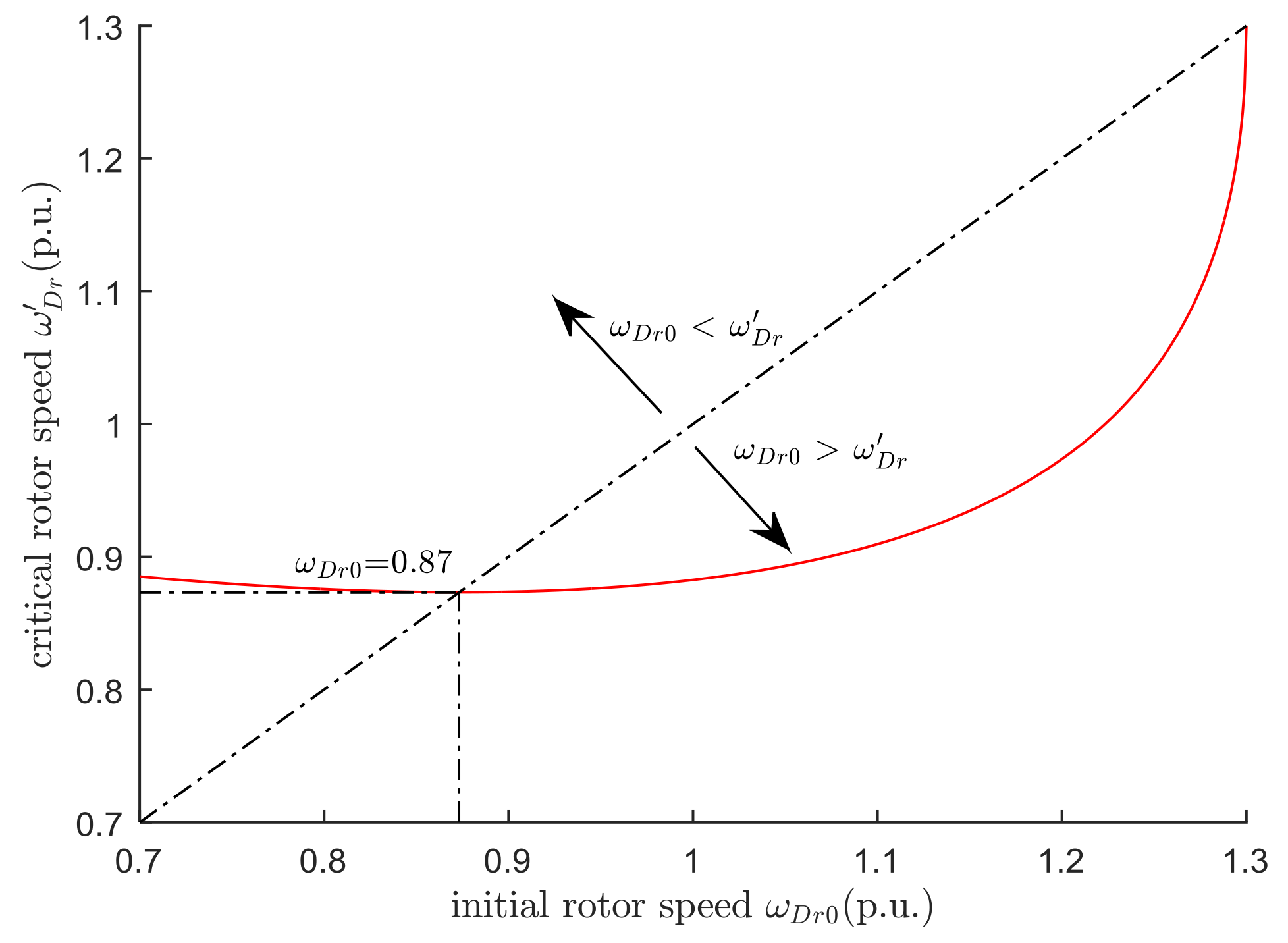
Furthermore, the applicability of the proposed method is discussed. According to the definition of the critical rotor speed, when the initial rotor speed
,
is positive; thus, the reactive power capacity of DFIG is limited by the converter current and the rotor speed. When
,
can be set as 0. So, no difference exists between the proposed method and the conventional method without considering the rotor speed. The conventional method can be regarded as an exceptional condition of the proposed method. In the common rotor speed region,
changes with the increase of
, as
Figure 9 shown.
Figure 9 shows that when the initial rotor speed
exceeds 0.87 p.u., it will be larger than the critical rotor speed
. It is essential to consider the rotor speed constraint on reactive power when the initial rotor speed is between 0.87 and 1.30 p.u. The proposed method can be applied in most of the maximum-power point-tracking region (0.87–1.20 p.u.). In the constant speed region, the pitch angle is a positive value that is increasing along with the wind speed while the rotor speed maintains the rated value. Adjusting
to 0 in the constant speed region is faster than that under the rated condition. Thus, the calculation result in the rated condition is also applicable for the constant speed region. The proposed method has a relatively large application scope.
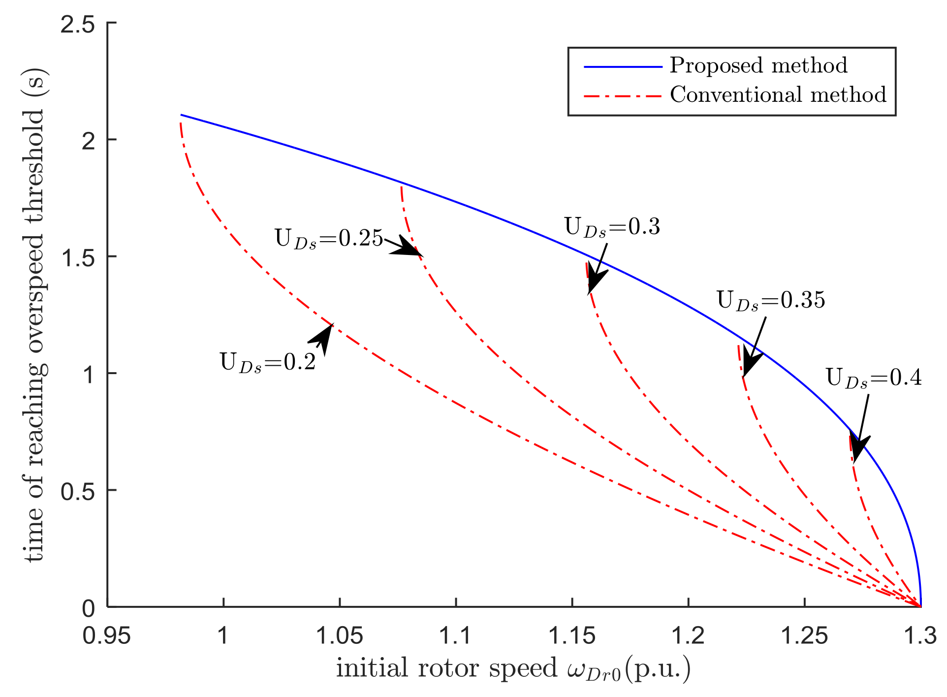
Figure 10 shows the time of reaching the overspeed threshold with the proposed method and conventional method. The time decreases with the initial rotor speed
increasing. The left end of red dash-dot line presents the minimum rotor speed
at which rotor speed can reach the overspeed threshold. When
is smaller than
, the DFIG provides more reactive power with the proposed method than that with the conventional method; when
is larger than
, it takes more time to reach the overspeed threshold with the proposed method than that with conventional method, which means that it is more safe.
For example, when
is 0.3 p.u.,
is 1.156 p.u. Two kinds of initial rotor speed conditions are compared in
Table 2. When
is 1.1 p.u., the reactive power of DFIG is 0.2435 p.u. with the proposed method, which is greater than that with the conventional method. When
is 1.2 p.u., it takes 1.286 s to reach the overspeed threshold and the rotor decelerates afterwards with the proposed method. The DFIG will not trip. While with the conventional method, the rotor speed exceeds the overspeed threshold at 0.704 s and continues to increase which leads to tripping.


