Suppression of Squeal Noise Excited by the Pressure Pulsation from the Flapper-Nozzle Valve inside a Hydraulic Energy System


1
Department of Fluid Control and Automation, Harbin Institute of Technology, Harbin 150001, China
2
MCC Huatian Engineering & Technology Corporation, Nanjing 210019, China
*
Authors to whom correspondence should be addressed.
Energies 2018, 11(4), 955; https://doi.org/10.3390/en11040955
Submission received: 25 February 2018
/
Revised: 11 April 2018
/
Accepted: 13 April 2018
/
Published: 17 April 2018
Abstract
:Squeal noise often occurs in a two-stage electrohydraulic servo-valve, which is an unfavorable issue of modern hydraulic energy systems. The root causes of such noise from the servo-valve are still unclear. The objective of this paper is to explore the noise mechanism in a servo-valve excited by the pressure pulsations from the hydraulic energy system perspective. The suppressing capability of squeal noise energy is investigated by changing the pressure pulsation frequency and natural frequency of the flapper-armature assembly. The frequencies of the pressure pulsations are adjusted by setting different speeds of the hydraulic pump varying from 10,400–14,400 rpm, and two flapper-armature assemblies with different armature lengths are used in the tested hydraulic energy system. The first eight vibration mode shapes and natural frequencies of the flapper-armature assembly are obtained by numerical modal analysis using two different armature lengths. The characteristics of pressure pulsations at the pump outlet and in the chamber of the flapper-nozzle valve, armature vibration and noise are tested and compared with the natural frequencies of the flapper-armature assembly. The results reveal that the flapper-armature assembly vibrates and makes the noise with the same frequencies as the pressure pulsations inside the hydraulic energy system. Resonance appears when the frequency of the pressure pulsations coincides with the natural frequency of the flapper-armature assembly. Therefore, it can be concluded that the pressure pulsation energy from the power supply may excite the vibration of the flapper-armature assembly, which may consequently cause the squeal noise inside the servo-valve. It is verified by the numerical simulations and experiments that setting the pressure pulsation frequencies different from the natural frequencies of the flapper-armature assembly can suppress the resonance and squeal noise.
1. Introduction
Hydraulic control energy systems are widely used in the mechanical industry, which can control the airplane or missile wings requiring very high power density. The electrohydraulic servo-valve is the heart of these hydraulic energy systems. It is the ideal interface device between the low-power electrical control signals and high-power actuation. However, the servo-valve is more often troubled by the self-excited noise felt as squeal noise in the aerospace field [1,2,3]. It can deteriorate the performance of the servo-valve and even give rise to the failure of the hydraulic energy system. Meanwhile, the unfavorable noise is accompanied by the pressure pulsations in the flapper-nozzle valve flow field and the high-frequency vibration of the flapper-armature assembly of the servo-valve [4].
To date, understanding of the noise in flow control valves has been provided by many analyses. Several hypotheses to identify the cause of noise were proposed. Yi et al. [5] revealed that the Helmholtz resonance induced the squeal noise. They stated that the frequency of the squeal noise increased with a larger cavitation volume in the poppet valves. The instability of the shear layer resulting in the squeal noise in the counterbalance valve was reported in [6]. In addition, Watton [7] discussed the sufficient condition for the high frequency noise and stated that it had a relation to the oil supply pressure and return pressure in the two-stage servo-valve. According to some authors, vortex shedding in the valve can also induce noise. Smith [8] observed that the noise was caused by vortex shedding over the valve seat cavity coupled with an acoustic resonance across the throat of the valve. The study of Tamura et al. [9] concluded that the acoustic waves causing flow-acoustic resonance were generated by the unsteady vortices in the stub pipes of the safety relief valves. An expansion wave generated around the downstream corner was found in their studies. Besides, vibrations were also induced by vortex shedding due to some interior valve geometries or integrated parts from the research of Janzen et al. [10].
It is noticeable that the noise also can be generated by the mechanical vibration. Some other researchers revealed that the pressure pulsation is a very dominant factor for producing vibration in flow control valves. According to the research results from Yonezawa et al. [11], both occurrence conditions for the forced vibration and self-excited vibration of a Venturi-type valve were clarified. It was found that the greater pressure pulsations caused by the unsteady flow and negative damping acting on the valve head played a major role in the transition between the forced vibration and self-excited vibration of the Venturi-type valve. The pressure pulsations became periodic with the same frequency as that of the valve head vibration when the self-excited vibration appeared in their work. In the study of Misra et al. [12], the self-excited vibration occurred when the negative hydraulic stiffness, water hammer and high acoustic resistance were close to each other. It was concluded that the pressure fluctuation was a key spark for the self-excited vibration based on the fluid-structure dynamic model. Furthermore, in the surveys interested in this, some works have been investigated with respect to flapper-nozzle valve. The flapper-nozzle-type servo-valves were recognized as the mechanical vibration sources in the studies of Wakui [13]. It was proven that the high frequency vibration of the servo-valve body was suppressed remarkably by using viscoelastic materials. Bergada et al. [14] explored how the pressure pulsations and forces acting on the flapper caused by flows going from the nozzle to the flapper could induce the instability vibration of the armature. Kawashima et al. [15] analyzed how using a slit structure instead of an orifice plate could reduce the pressure fluctuation by 75% and the noise level approximately by 15 dB in the flapper-nozzle type servo-valve. Peng et al. [4,16] also studied how the pressure pulsations could induce resonance excitation in the flapper-nozzle valve. They indicated that self-excited oscillation of the flapper-armature generated by the fluid-structure interaction can cause the self-excited noise and squeal noise. Nevertheless, the relationships between the pressure pulsations, armature vibration and noise were not revealed in their studies. Moreover, a number of studies have shown the flow field characteristic inside the flapper-nozzle valve and reported that the pressure pulsations and noise could be generated by the cavitation phenomenon under some certain conditions [17,18,19].
Therefore, the pressure pulsation is one of the main causes of the vibration and noise of the valve according to the previous works. The pump parameters such as the pump speed, piston number and maximum supply pressure greatly affected the pressure pulsations of the hydraulic energy system and its components in practice [20,21,22]. However, from the previous works, it can be seen that the self-excited (squeal) noise of the servo-valve has been paid little attention in their studies since it was hardly excited by the servo-valve in the experiment. The occurrence of the squeal noise was not only dependent on the servo-valve structure, but also highly influenced by the whole hydraulic energy system characteristics. Therefore, to explore the mechanism of the squeal noise of the servo-valve, a hydraulic energy system to control airplane swing with the characteristic of a very high power-mass ratio is investigated in this paper, which can produce squeal noise easily. The pump speeds are adjusted to change the pressure pulsations traveling through the whole hydraulic energy system. Moreover, the pressure pulsations at the pump outlet and in the chamber of the flapper-nozzle, armature vibration and noise are all analyzed from the hydraulic system perspective in this paper.
2. Instability Analysis of the Flapper-Armature Assembly
2.1. Transmission of the Pressure Pulsations inside a Hydraulic Energy System
In this paper, the hydraulic energy system mainly includes an axial piston pump, a servo-valve and a processing unit (computer). The axial piston pump including nine pistons is driven by a variable-speed motor. One noticeable point is that the source flow ripple radiated from the axial piston pump can interact with the characteristics of the hydraulic circuit to produce pressure pulsations in the hydraulic energy system [22,23,24]. The pressure pulsations are transmitted from the source (pump) through the servo-valve to the oil tank. Therefore, the frequencies of the pressure pulsations traveling in the whole hydraulic energy system are mostly governed by the motor speed. Generally, the natural pressure pulsations and backflow pressure pulsations can be found in the hydraulic energy system caused by the axial piston pump [21,25].
From the characteristic of the axial piston pump, the natural frequency of the pressure pulsations for an odd number of pistons (nine pistons of the pump used in this work) can be defined as [20,25]:
The backflow frequency of the pressure pulsations is [20,25]:
where fpn is the natural frequency (Hz), fpb is the backflow frequency (Hz), z is the number of pistons of the axial piston pump and n is the motor speed (rpm).
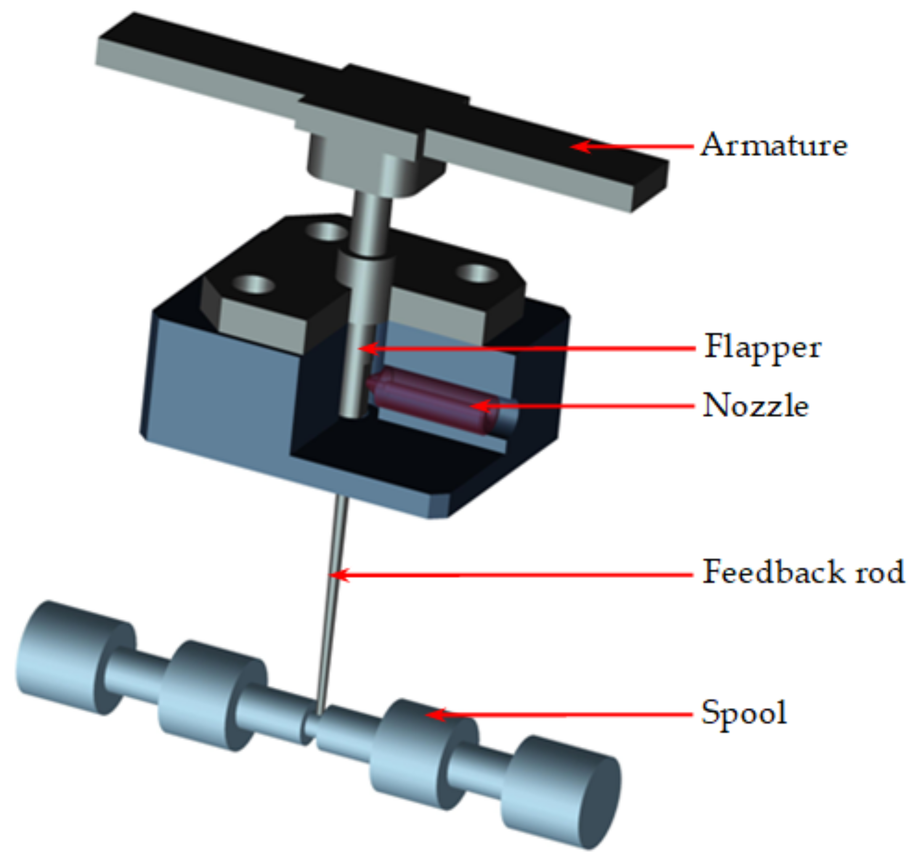
The flapper-nozzle electrohydraulic servo-valve is composed of a flapper, a nozzle, an armature, a feedback rod and a spool, as shown in Figure 1. The flapper-nozzle valve serves as an electro-hydraulic converter and plays a vital role in achieving accurate movement of the spool. When the input current is zero to the torque motor, the flapper remains in the neutral position, which equally controls the flow from twin nozzles balancing the pressures on both sides of the spool. On the other hand, the torque motor can rotate the flapper clockwise or contour-clockwise, being subject to nonzero input current. Therefore, the unbalanced pressures on the left and right sides of the nozzle cause the spool to move in the net pressure direction. Following along the spool movement, the feedback rod attains a tension and finally overcomes the torque motor force and pulls back the flapper. The spool remains at the required flow control position proportional to the input current. Thus, the static and dynamic characteristics of the flapper-nozzle valve are significant in the design of the servo-valve.
2.2. Forces Working on the Flapper-Armature Assembly
Although the flapper works in a fluid environment and the fluid may exert an influence on the vibration of the flapper by changing the natural frequency or increasing the viscous damping, its influence is actually negligible. Therefore, the influence from the fluid on the vibration of the flapper can be omitted. To achieve a clear judgment of the instability of the flapper-armature assembly, the movement and force of the flapper-armature assembly are analyzed. Figure 2 describes the angular movement of flapper-armature assembly. The governing equation for the angular movement of flapper-armature assembly is given as:
where Td is developed torque by magnetic force, θ is the rotary angle of the flapper-armature assembly, J is the rotational inertia of the flapper-armature assembly, B is the damping, K is the stiffness matrices and TL is the load torque.
On the other hand, the total net torque developed on the armature can be linearized as:
where ∆i is the input current difference to the coil, Kt is the torque constant and Km is the magnetic spring constant.
The load torque can be calculated by:
where TN is the load torque from the nozzle, Ts is the load torque from the spool valve, F1 and F2 are the forces due to the flows acting on two sides of the flapper, respectively, Tf is the feedback rod force, pLp is the pressure difference between the two nozzles, AN is the area at the nozzle, Xf0 is the flapper nozzle null clearance, xf is the flapper displacement from null position, Cdf is the discharge coefficient, ps is the supply pressure of the hydraulic energy system, r is the distance between the nozzle centerline and center of rotation, b is the distance between the nozzle centerline and spool valve and xs is the displacement of the spool valve.
To explore the mechanism of the noise from the flapper-nozzle valve in this paper, the input current difference to the coil is always kept at zero to rule out the external force as a contributing factor. Therefore, according to the above force analysis, the forces due to the flows (F1 and F2) play a major role in the instability of the flapper-armature assembly at the zero input current condition. Specifically, it is reasonable to see that the unavoidable pressure pulsations of the F1 and F2 in the flapper-nozzle valve traveling from the source (axial piston pump) could result in the instability of the flapper-armature assembly, which favors the occurrence of undesirable noise. Meanwhile, the pressure pulsations radiating from the pump are greatly dependent on the shaft speed of the pump. Therefore, it is very necessary to investigate the characteristics of the pressure pulsations at different motor speeds.
3. Modal Analysis of the Flapper-Armature Assembly
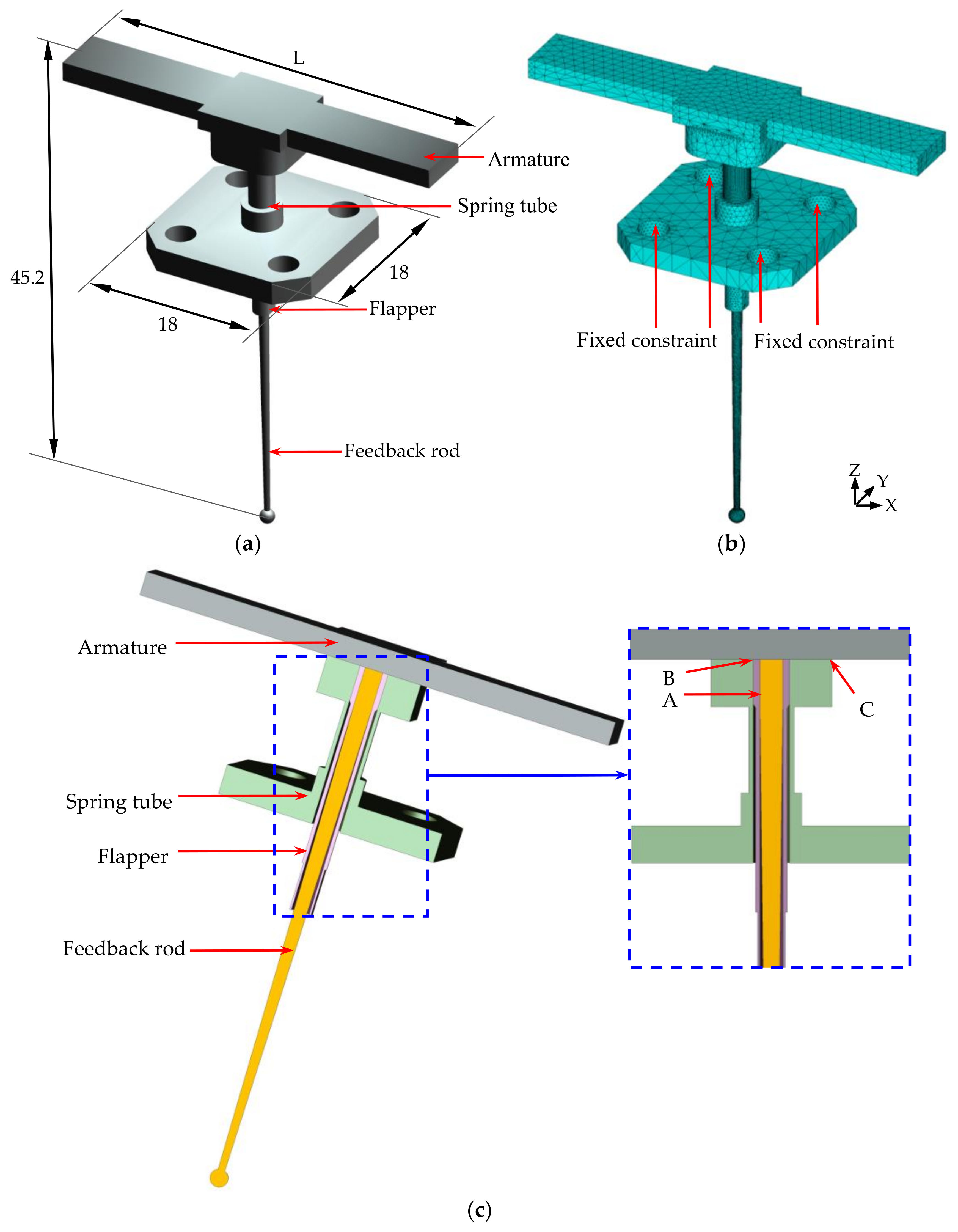
Figure 3a shows the 3D geometry model and the main dimensions of the flapper-armature assembly. To study the suppression of the squeal noise, the natural frequencies of the flapper-armature assembly are changed by setting different armature lengths. The length of the armature (L) is set as 40 and 48 mm for two different flapper-armature assemblies (Types A and B). The other geometry dimensions are the same between Type A and B flapper-armature assemblies. The finite element model is established by using the tetrahedron element type and meshed with a free mesh as shown in Figure 3b. The fixed constraint boundary conditions are set on the four flange holes. As depicted in Figure 3c, firstly, the feedback rod and flapper are connected by the interference fit at Location A. Then, the flapper is installed in the spring tube by laser tack-welding at Location B. In addition, the spring tube is also connected to the armature by laser tack-welding at Location C. Finally, the spring tube is bolted to the main part of the servo-valve. The material properties of the flapper-armature assembly are shown in Table 1. The block Lanczos method is used to extract the modal parameters of the flapper-armature assembly.
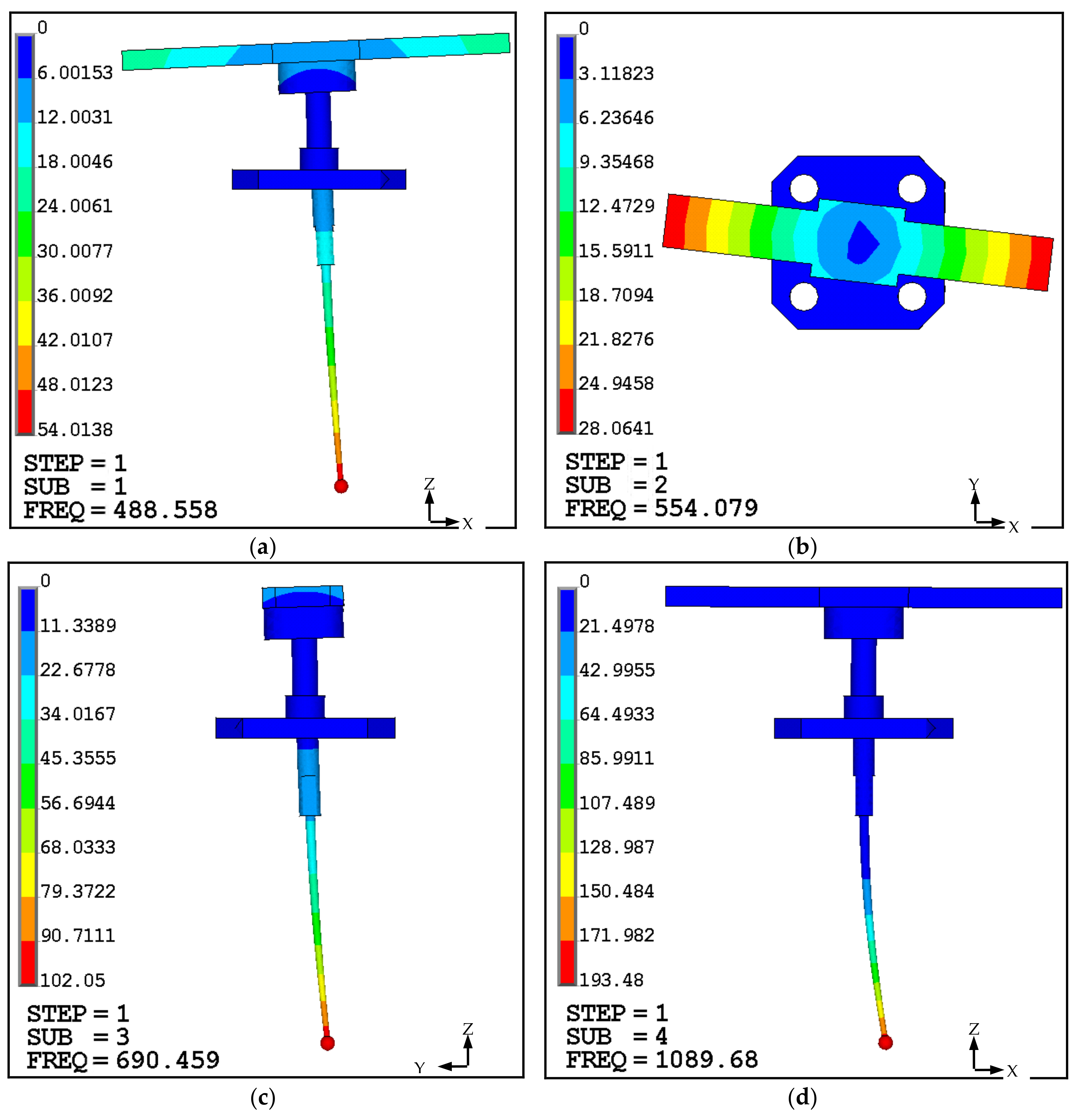
The first eight natural frequencies and mode shapes of the flapper-armature assembly are obtained as demonstrated in Figure 4 with the Type A flapper-armature assembly. The SUB represents the modal order and the FREQ is short for frequency in Figure 4 and Figure 5. It can be observed that the armature vibrates with the first and second modes in the form of whole rotation in the XZ and XY plane, respectively. In addition, the third mode is the swinging style in the YZ plane. Then, the fourth, fifth, sixth and seventh modes behave as second order bending vibration. Finally, the warping vibration occurs in the eighth mode in the XZ plane with a natural frequency of 3747 Hz for the largest deformation at the end of the armature. Furthermore, the eighth mode shapes for the Type B flapper-armature assembly are shown in Figure 5, in which the resonance is more likely to occur in this study. Additionally, the other seven mode shapes for the Type B flapper-armature assembly have a fair agreement with those of Type A correspondingly. The natural frequencies corresponding to these mode shapes for the Type A and Type B flapper-armature assemblies can be seen in Table 2.
4. Measurement of the Pressure Pulsations, Vibration and Noise
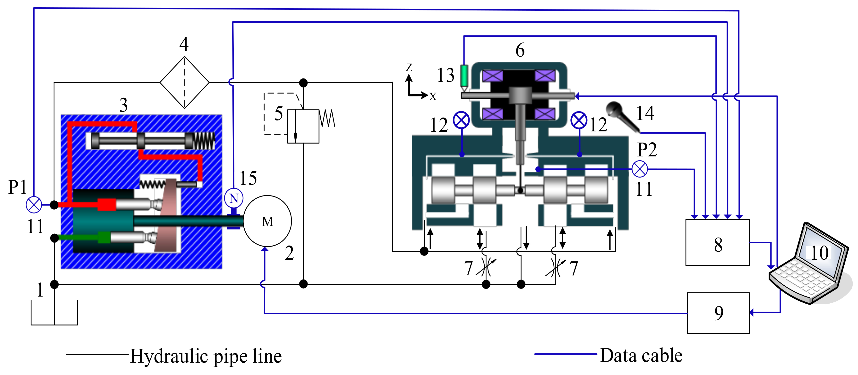
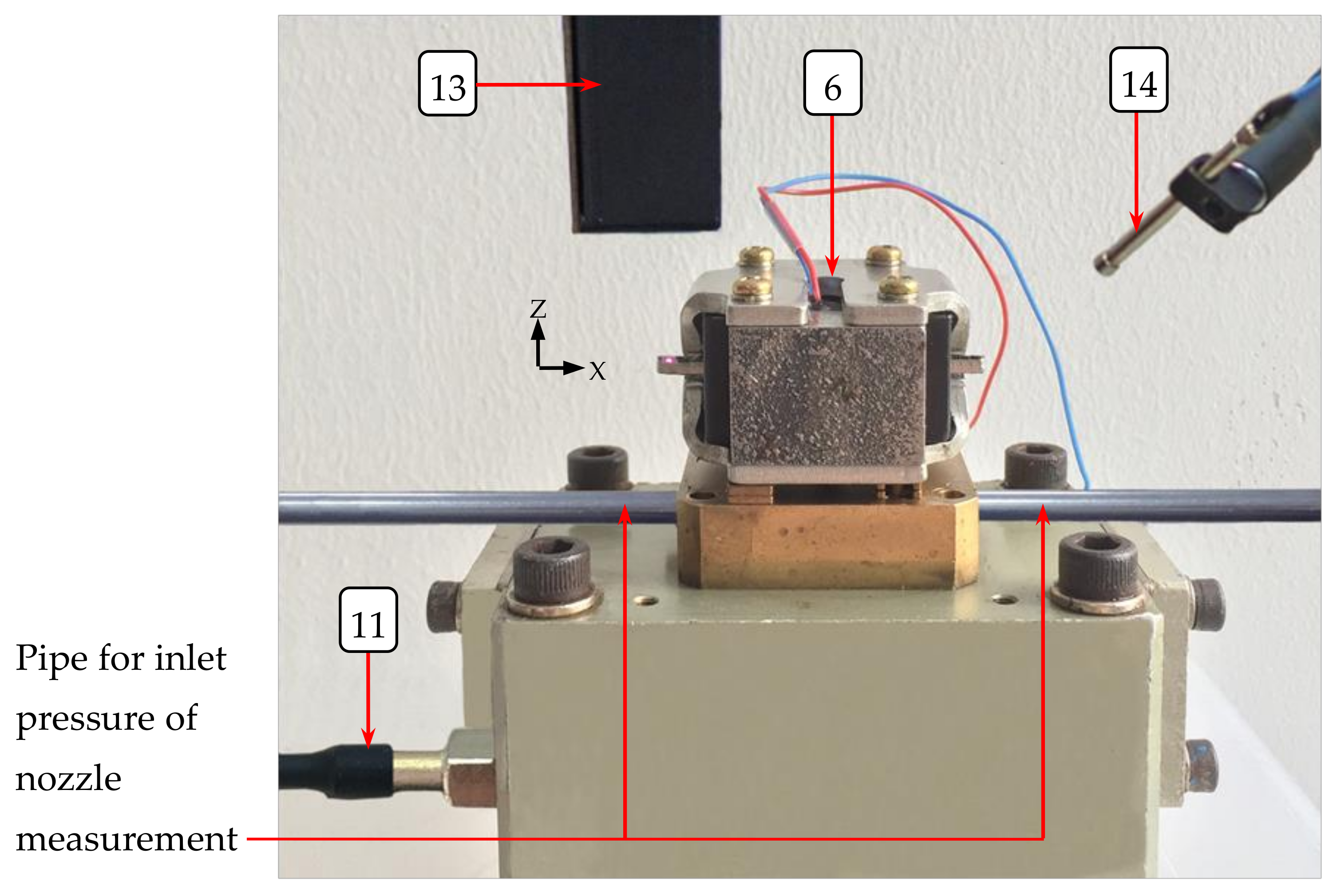
To discover the effect of the pressure pulsations as the main excitation to the flapper-armature assembly, the input current to the servo-valve is set to zero, which can exclude the external force as the excited force from the energy circuit to the armature vibration. This hydraulic energy system is used in the aerospace industry, which requires very high power density. The pump speeds can just be adjusted to high speeds from 10,000–15,000 rpm in our actual application. The 12,400 rpm speed corresponds to the rated flow rate of the pump. Therefore, in this experiment, the pressure pulsations at pump outlet (P1) and in the chamber of the flapper-nozzle valve (P2), armature vibration and noise are experimentally measured and compared at five different pump speeds of 10,400, 11,400, 12,400, 13,400 and 14,400 rpm using two types of flapper-armature assemblies (Types A and B) with different armature lengths. Figure 6 shows the schematic diagram of the experimental setup. It comes in two parts: the hydraulic part and the control part. The hydraulic part is mainly composed of a motor, an axial piston pump, a two-stage servo-valve and two throttle valves. The control part consists of a piezoelectric pressure sensor, a piezoelectric microphone, a laser displacement sensor, a data-acquisition board, a motor controller and a processing unit (computer). The axial piston pump has a capacity of 20 L/min, the rated pressure of which is 18 MPa. In addition, the rated supply pressure of the two-stage servo-valve is 21 MPa, and the rated flow rate is 20 L/min (5 MPa for valve pressure drop). The throttle valves are installed to simulate a load on the valve. The picture of the tested servo-valve is shown in Figure 7.
In every run, a stable flow condition firstly is attained by setting the required motor speed. As shown in Figure 6, the pressure pulsations at P1 and P2 are measured by a piezoelectric pressure sensor (113B22, PCBPIEZOTRONICS Co., Ltd.: New York, NY, USA). At the same time, the armature vibration in the Z direction is recorded by the laser displacement sensor (LK-G5000, KEYENCE Co., Ltd.: Itasca, IL, USA), whose measurement range is from −3 mm–+3 mm, and resolution is 0.01 μm. Meanwhile, the noise is recorded by a piezoelectric microphone (130E22, PCBPIEZOTRONICS Co., Ltd.: New York, NY, USA), which is placed 0.02 m away from the servo-valve. The data of these parameters are recorded simultaneously and sent to the processing unit (computer) through the data-acquisition board. The sampling frequency of the pressure pulsations and noise is 10 kHz. The oil properties can be seen in Table 3. In addition, to ensure the twin nozzles have the same pressures for every run, two inlet pressures at the nozzles are measured by the pressure gauges. In every run, the flapper is always maintained at the center position during the measurement processes by setting zero input current from the computer at different motor speeds. The related details of the experimental apparatus can be seen in Table 4.
5. Results and Discussion
5.1. Pressure Pulsations’ Characteristics
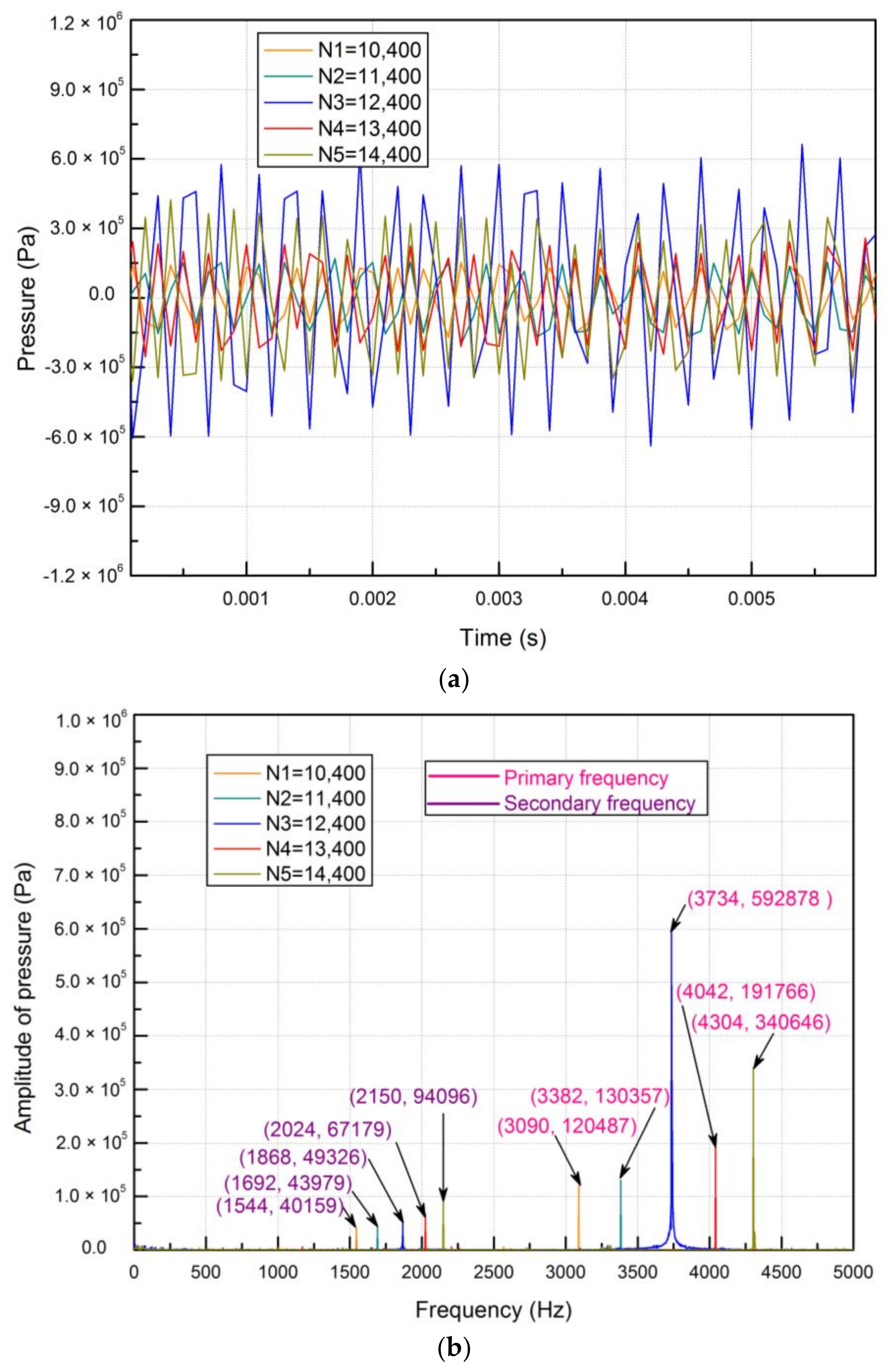
The characteristics of the tested pressure pulsations at the pump outlet (P1) for the Type A flapper-armature assembly can be seen in Figure 8. Figure 8a shows the measured pressure pulsations in the time domain for a specific duration for five different motor speeds of 10,400, 11,400, 12,400, 13,400 and 14,400 rpm, respectively. At the lowest speed of 10,400 rpm, the amplitude of the measured pressure pulsations is about 1.2 × 10⁵ Pa. With the increment of the motor speed, the amplitude of the pressure pulsations increases gradually except at the speed of 12,400 rpm. Abnormally, the amplitude of the pressure pulsations dramatically increases to about 6 × 10⁵ Pa when the motor speed rises to 12,400 rpm. Then, the amplitude of pressure pulsations reduces back to around 2 × 10⁵ Pa when the motor speed is adjusted to 13,400 rpm.
The frequencies of the measured pressure pulsations at P1 for the five different motor speeds are compared in Figure 8b. The frequency spectrum contains two distinct frequencies of pressure pulsations (primary and secondary frequencies) with peak amplitudes for different motor speeds. All the primary frequencies are double the secondary frequencies. This phenomenon appears due to the fact that the axial piston pump produces primary frequencies corresponding to the natural pulsation frequency. The secondary frequencies are dependent on the backflow pulsation frequency. Besides, the amplitudes of pressure pulsations corresponding to primary frequencies (hereafter referred to as primary pressure pulsations) are larger than those for secondary frequencies (hereafter referred to as secondary pressure pulsations) for every motor speed. This reveals that the primary pressure pulsations dominate the pressure wave propagated in the whole hydraulic energy system. Moreover, it can be noted that both the primary and secondary frequencies of the pressure pulsations increase with the increment of the motor speeds. The smallest amplitudes of primary pressure pulsations are 1.2 × 10⁵ with the lowest primary frequencies of 3090 Hz for the case of 10,400 rpm. Unusually, the largest amplitude is 5.9 × 10⁵ Pa with a primary frequency of 3734 Hz at a motor speed of 12,400 rpm. In addition, the amplitude of the pressure pulsations increases with the increment of the motor speed except at the speed of 12,400 rpm.
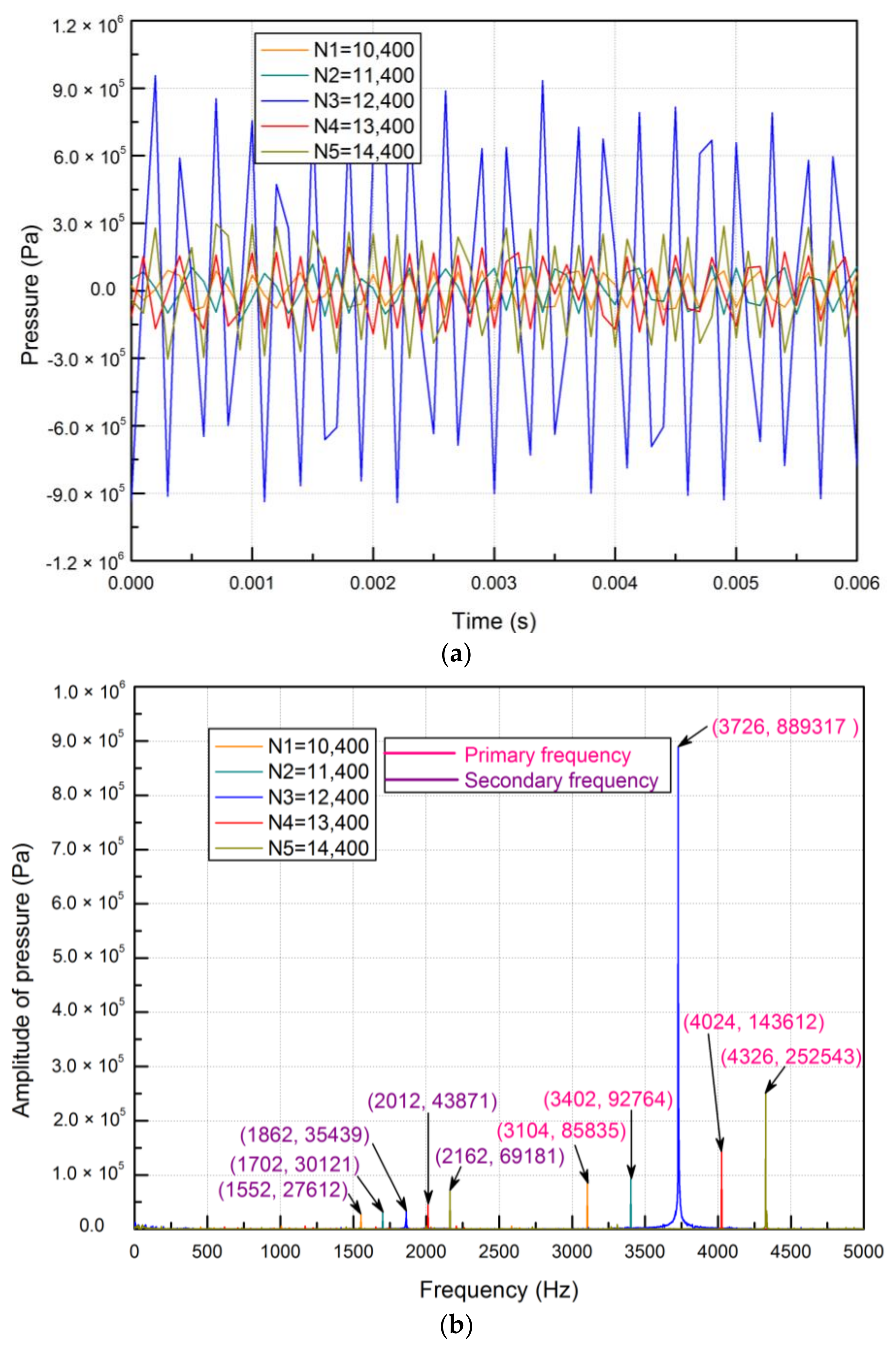
Figure 9a,b shows the comparison of the experimental pressure pulsations in the chamber of the flapper-nozzle (P2) with different motor speeds for the Type A flapper-armature assembly. One can observe that the primary and secondary frequencies at P1 and P2 are consistent, and these frequencies are close to each other at every motor speed. This proves that the pressure pulsations with the primary and secondary frequencies were generated by the axial piston pump and traveled through the whole hydraulic energy system. Therefore, P1 and P2 located at the upstream and downstream of the hydraulic energy system share a common pressure pulsations source. On the other hand, the amplitudes of the pressure pulsations at P1 are larger than those at P2 for every motor speed except at the speed of 12,400 rpm. The reason is that the pressure pulsations decrease constantly due to the influence of flow resistance and friction of the pipeline and hydraulic components.
5.2. Armature Vibration Characteristics
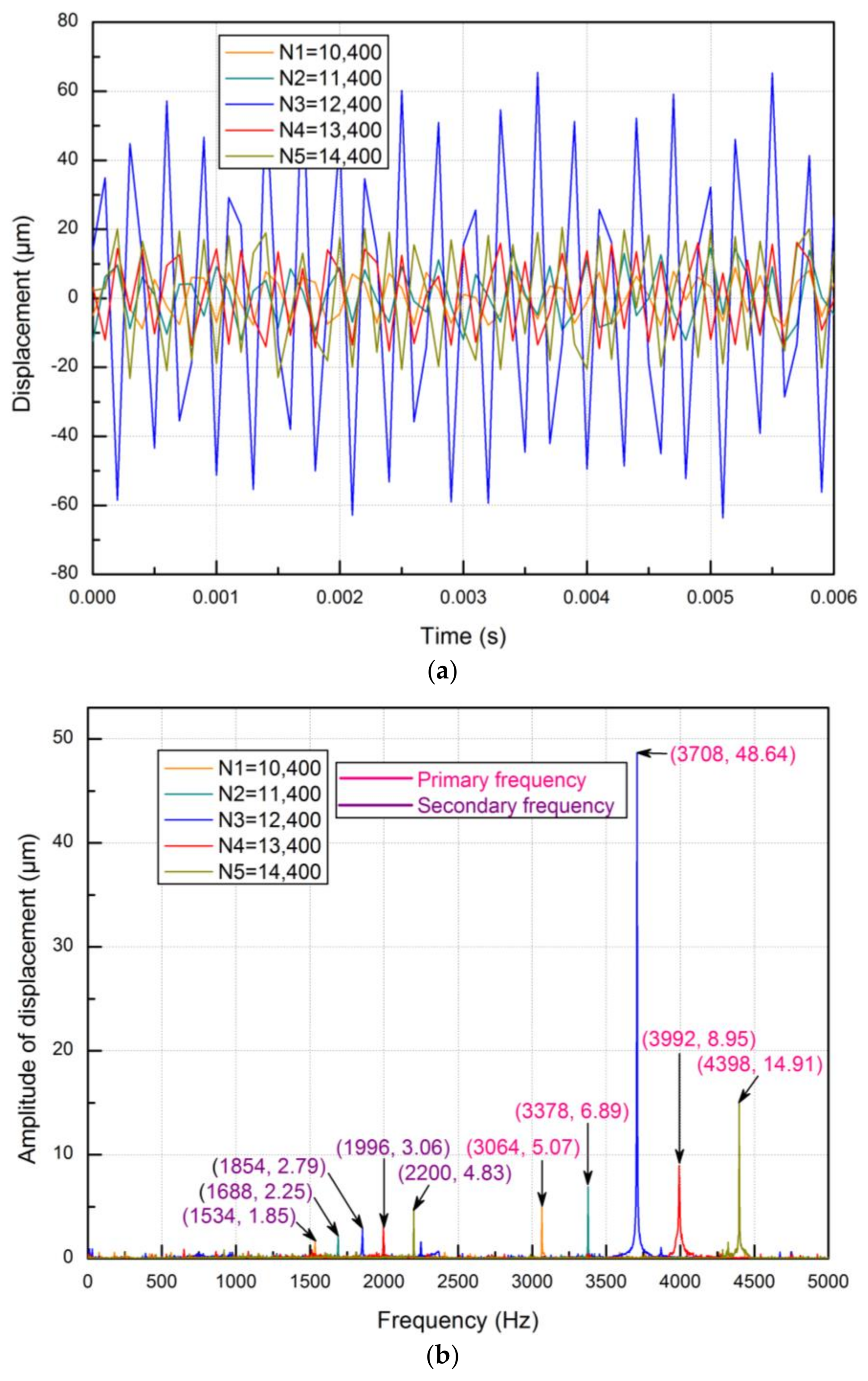
To explore the unusual phenomenon of the abrupt amplitude change of the primary pressure pulsations at the speed of 12,400 rpm for the Type A flapper-armature assembly, the armature vibration and servo-valve noise are studied. It is very difficult to perform direct measurement of the flapper vibration due to its structural limitation. According to the servo-valve construction, the armature is rigidly connected to the flapper, which directly interacts with the flow field. Thus, it is reasonable to measure and analyze armature vibration. Figure 10a,b presents the responses of the endpoint of the armature vibration along the Z-direction for the Type A flapper-armature assembly. The characteristics of the armature vibration show a great similarity to the characteristics of the measured pressure pulsations at P2. Generally, the higher frequency of armature vibration occurs at a higher motor speed, as shown in Figure 10b. As for the experimental pressure pulsations, a maximum amplitude of 48.64 μm with a primary frequency of 3708 Hz were found at the motor speed of 12,400 rpm, which is also far stronger than those in any other motor speeds. One noticeable point is that the armature vibration is correlated greatly with the experimental pressure pulsations at P2. As for the previous analysis, the pressure pulsations are the main unstable forces acting on the flapper when the input current is zero. The pressure pulsations are magnified sharply at the motor speed of 12,400 rpm for the Type A flapper-armature assembly because resonance occurs. Therefore, it can be concluded that the armature vibration is the excitation response of the pressure pulsations in the flapper-nozzle valve.
5.3. Noise Characteristics
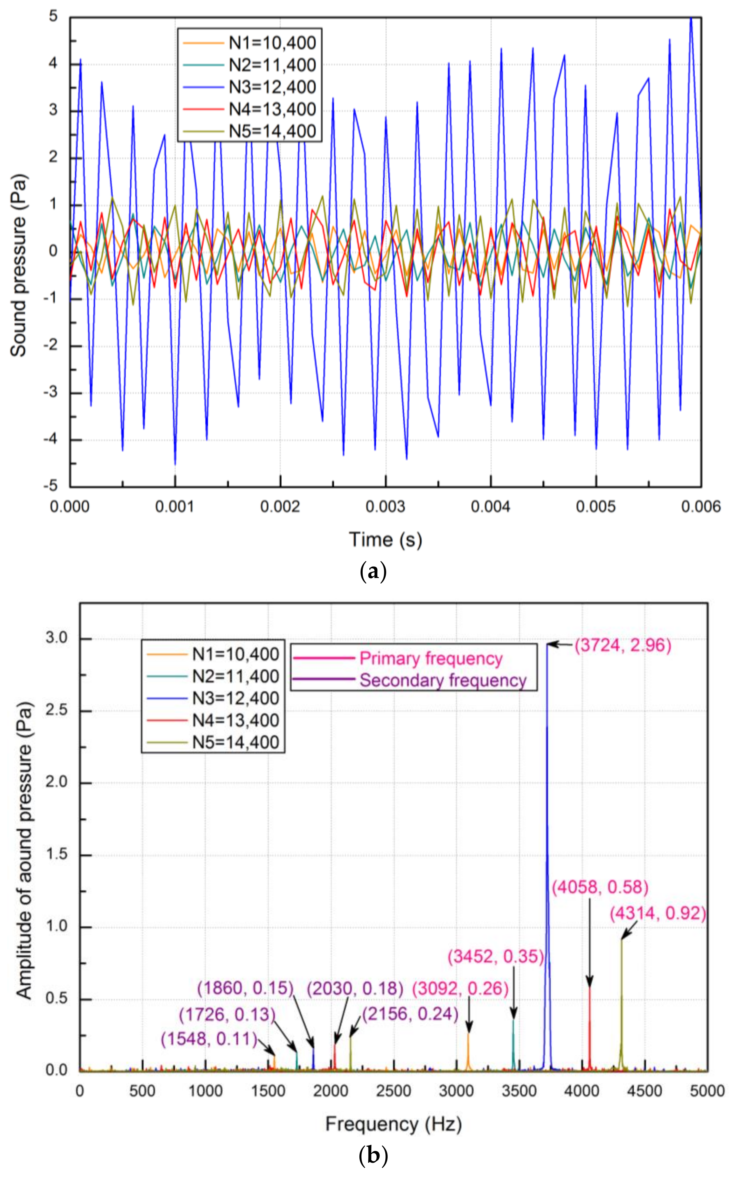
To study the noise characteristics, the noise is recorded in terms of sound pressure for the same specific duration. Figure 11a,b shows the recorded sound pressure in the time domain and frequency domain using the Type A flapper-armature assembly. The noise characteristics also agree well with the characteristics of the armature vibration and measured pressure pulsations at P2 for the Type A flapper-armature assembly. The primary frequencies of the sound pressure increase from 3092–4314 Hz with the increment of motor speed. Meanwhile, the amplitude also increases continuously with the increment of motor speed except for the case of 12,400 rpm, at which the highest sound pressure of 2.96 Pa was found with the primary frequency of 3724 Hz. It can be understood that the experimental pressure pulsations, armature vibration and noise all produce amplification amplitudes with approximate frequencies at the same motor speed of 12,400 rpm using the Type A flapper-armature assembly.
5.4. Results Comparison
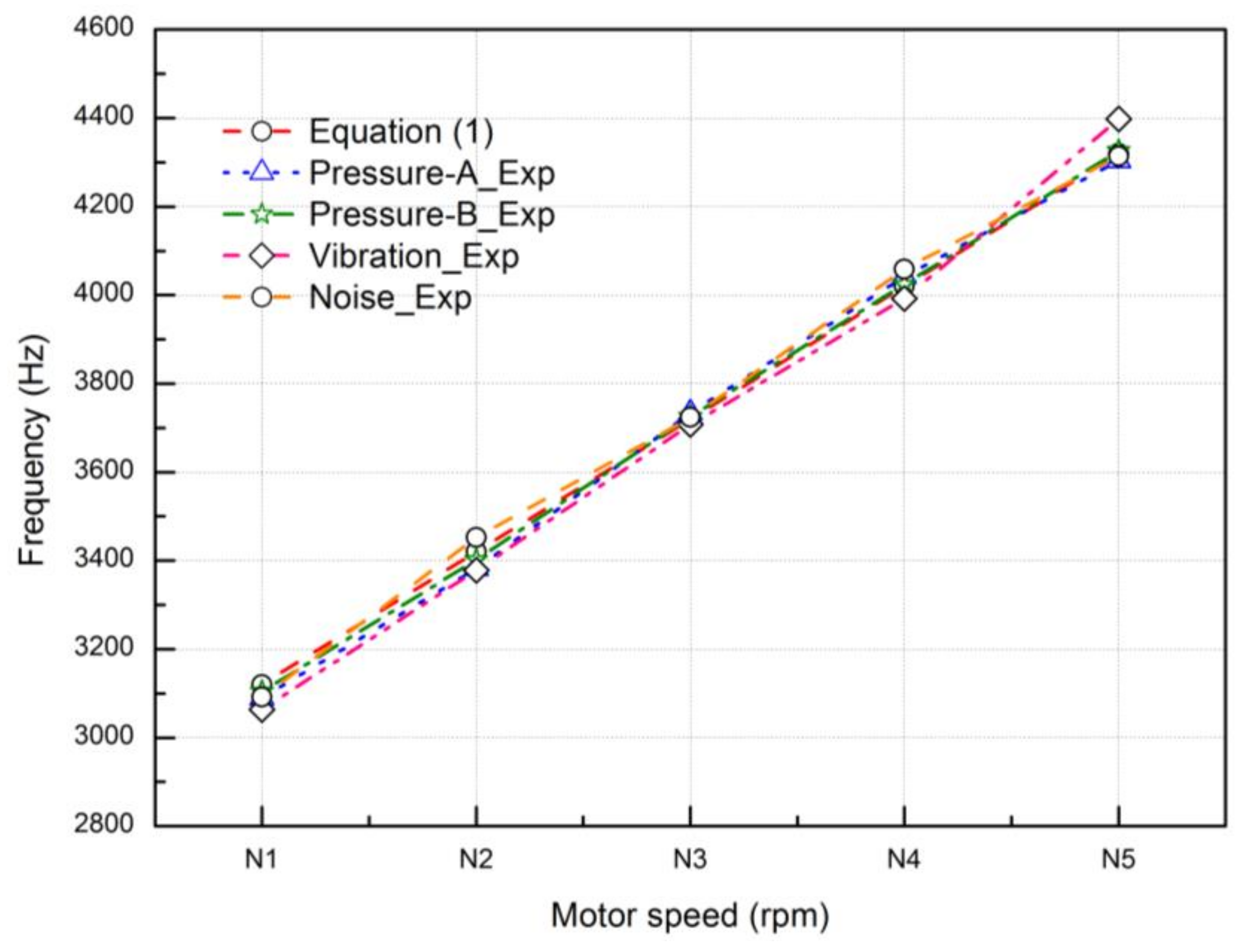
All the calculated frequencies corresponding to natural frequency (Equation (1)) and experimental frequencies are shown in Table 5. The “Rev” is short for the revolution. The resonance frequencies of the experimental pressure pulsations at P1 and P2, armature vibration and noise are 3734, 3726, 3708 and 3724 Hz, respectively, for the Type A flapper-armature assembly. Here, the eighth-order natural frequency of the flapper-armature assembly in the XZ work plane is around 3747 Hz for the Type A flapper-armature assembly as shown in Figure 4, when the largest deformation appears at the end of the armature. Hence, it is noticeable that the resonance frequencies of the investigated experimental parameters (measured pressure pulsations at P1 and P2, armature vibration and noise) almost coincide with the eighth-order natural frequency for the Type A flapper-armature assembly when the squeal noise occurs.
For further understanding, the comparisons of the experimental parameters for the Type A flapper-armature assembly are holistically presented in Table 6. Figure 12 describes the comparisons of the frequencies between different motor speeds using the Type A flapper-armature assembly. The corresponding primary frequencies of the calculated pressure pulsations and experimental parameters (measured pressure pulsations at P1 and P2, armature vibration and noise) almost linearly increase in the range of 3064–4398 Hz with the increment of the motor speed. It also shows a well-matched trend between the calculated data and experimental data. In comparisons of these frequencies, the largest error is only 1.3%. This is because the characteristics of all the experimental parameters are radiated from the axial piston pump, creating the pulsation frequencies.
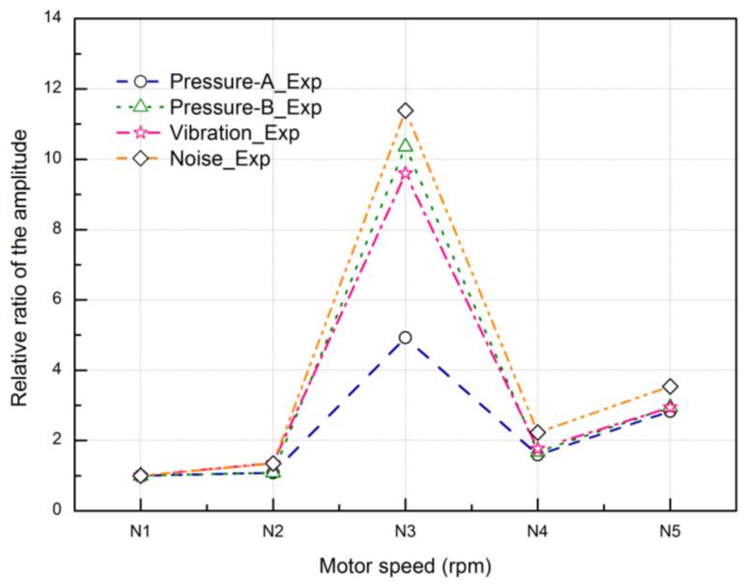
To compare the change of the amplitudes, the amplitudes of these investigated experimental parameters are normalized by setting the amplitudes at the lowest motor speed of 10,400 rpm as the reference ones. The relative amplitudes of these parameters at other motor speeds are obtained divided by the reference ones. Figure 13 describes the relative amplitudes of the investigated parameters corresponding to the different motor speeds using the Type A flapper-armature assembly. The results highlight that there is a set of resonance frequencies at which the amplitudes of measured pressure pulsations at P1 and P2, armature vibration and noise become peaks. The resonance condition magnifies the pressure pulsations tested at P2, armature vibration and noise greatly. In the resonance condition, the armature vibrates with peak amplitudes and enhances the self-excited noise heard as squeal noise to the surroundings. Here, we can notice that the amplitude of the pressure pulsations at P1 is smaller than that at P2 at the motor speed of 12,400 rpm for the Type A flapper-armature assembly, which has a distinct trend for these at other motor speeds. This is reasonable because P2 becomes the resonance source, when the self-excited oscillation of the flow field inside the flapper-nozzle valve occurs at the motor speed of 12,400 rpm.
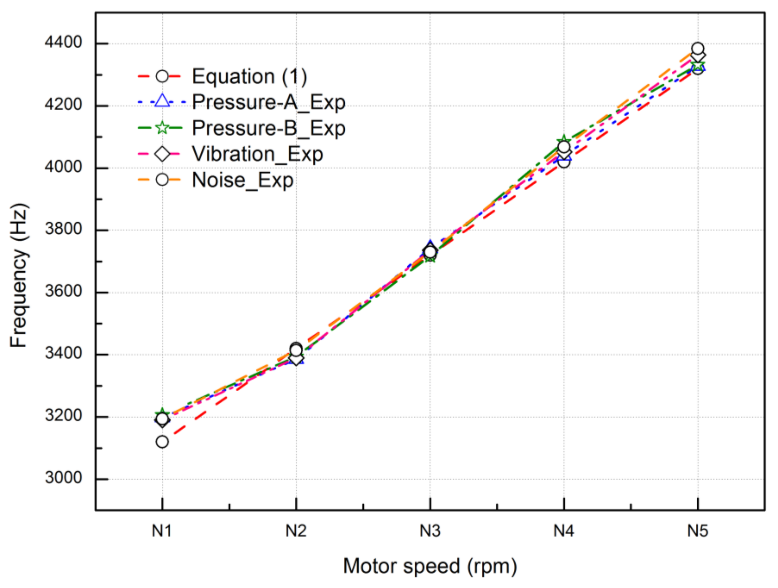
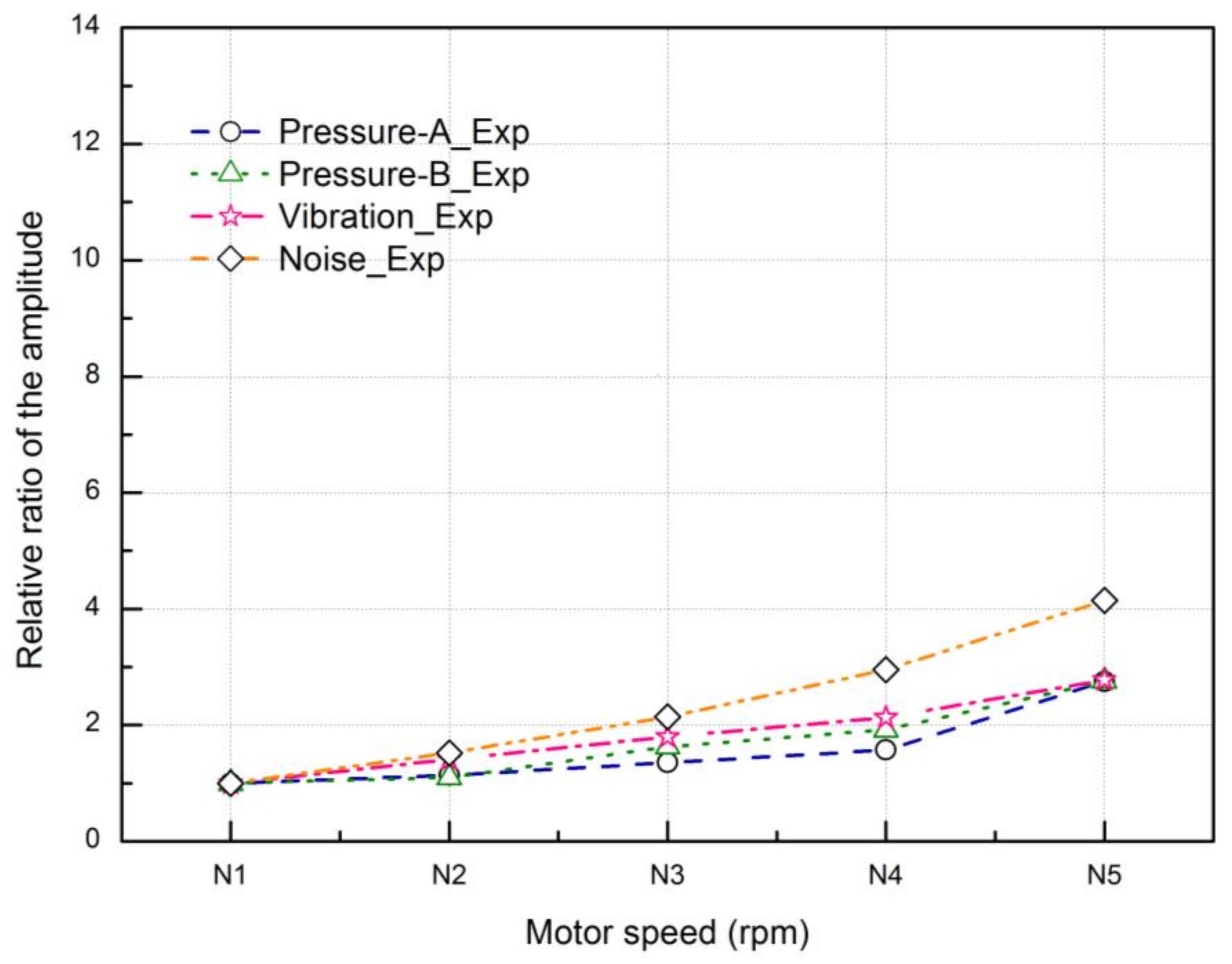
To verify the suppression capability of squeal noise, the natural frequencies of the flapper-armature assembly are changed by setting different armature lengths. The comparisons of the experimental parameters varying the pump speeds from 10,400–14,400 rpm for the Type B flapper-armature assembly are shown in Table 7. It can be observed that the frequency characteristics using the Type B flapper-armature assembly achieve a good agreement with those using the Type A flapper-armature assembly, as shown in Figure 14. However, the abrupt amplitude phenomenon disappears when the eighth natural frequency of the Type B flapper-armature assembly is very far away from the pressure pulsation frequencies, as described in Figure 15.
5.5. Mechanism and Suppression of the Noise
To sum up, the mechanism of the self-excited noise inside the flapper-nozzle valve can be identified as follows. The axial piston pump with rotational frequencies including primary and secondary frequencies as the source of the pressure pulsations greatly depends on the motor speed. It is confirmed that the frequencies of the pressure pulsations are intensified with the increment of motor speed. When the pressure pulsation frequency approaches the natural frequency of the flapper-armature assembly, it becomes the resonance frequency, which can magnify the pressure pulsations sharply in turn. Thus, the self-excited oscillation of the flow field inside the flapper-nozzle valve will cause the resonance of the flapper-armature, which propagates through air as a self-excited noise at high frequency felt as squeal noise. In this resonance condition, the flapper-armature vibrates with peak amplitudes that can enhance the noise to the surroundings. However, the self-excited noise can be suppressed by making the excited frequencies of the pressure pulsations near the flapper different from the natural frequencies of the flapper-armature assembly. Therefore, it can be concluded that the flow pressure pulsations inside the flapper-nozzle valve of the servo-valve comprise one of the possible causes of self-excited (squeal) noise.
6. Conclusions
In this paper, the system-dependent self-excited noise experienced as squeal noise from the flapper-nozzle valve of the servo-valve is investigated. The numerical modal analyses of the flapper-armature assembly are conducted using two different armature lengths by ANSYS. Experiments are performed to have a better understanding of the relationship between the pressure pulsations of the hydraulic energy system, armature vibration and noise characteristics. Frequencies of the pressure pulsations are changed by adjusting the driven motor speeds from 10,400–14,400 rpm in the experiments. Two different flapper-armature assemblies with different armature lengths installed on the servo-valve to change the natural frequency are tested in the experiments.
From the above discussion, it can be seen that the investigated parameters (experimental pressure pulsations at the pump outlet and in the chamber of the flapper-nozzle, armature vibration and noise) are strongly related to the pulsations source (pump) of the hydraulic energy system. Primary and secondary frequencies of the pressure pulsations in the hydraulic energy system are found in the frequency spectrum at every motor speed. The amplitudes of the pressure pulsations corresponding to primary frequencies are dominant, which play a significant role in the excitation to the armature vibration. The results show that all the primary and secondary frequencies of the investigated parameters increase with the increment of the driven motor speed. The axial piston pump with rotational frequencies is the source of the pressure pulsations in the flow field of the flapper-nozzle valve. Therefore, the frequency distribution of the investigated parameters in the experiments shows a well-matched trend with the change of motor speed. The results also confirm that the armature vibration is the response to the excitation of pressure pulsations around the flapper.
The resonance will occur with the amplitude increase of the pressure pulsations, armature vibration and noise, when the excitation frequency of the pressure pulsations matches the natural frequency of the flapper-armature assembly. It can induce the self-excited vibration of the armature propagating through air as a self-excited noise experienced as squeal noise. It is possible to suppress the self-excited (squeal) noise by keeping the frequency of the pressure pulsations very different from the natural frequency of the flapper-armature.
Acknowledgments
The authors would like to give acknowledgement to the National Natural Science Foundation of China (No. 51675119) for the financial support on the paper.
Author Contributions
Meng Chen carried out the numerical simulations and experiment analysis and wrote the paper. Dong Xiang helped the analysis with constructive discussions and provided a deeper insight into the related published work. Songjing Li built up the research project and was responsible for improving the quality of this article. Changfang Zou provided suggestions for the research.
Conflicts of Interest
The authors declare no conflict of interest.
References
- Zhang, K.; Yao, J.; Jiang, T. Degradation assessment and life prediction of electro-hydraulic servo valve under erosion wear. Eng. Fail. Anal. 2014, 36, 284–300. [Google Scholar] [CrossRef]
- Li, S.; Song, Y. Dynamic response of a hydraulic servo-valve torque motor with magnetic fluids. Mechatronic 2007, 17, 442–447. [Google Scholar] [CrossRef]
- Li, S.; Bao, W. Influence of magnetic fluids on the dynamic characteristics of a hydraulic servo-valve torque motor. Mech. Syst. Signal Process. 2008, 22, 1008–1015. [Google Scholar] [CrossRef]
- Peng, J.H.; Fan, Y.B.; Li, S.J. Modeling of armature-flapper assembly in a hydraulic servo valve by finite element analysis and acoustic excitation measurements. In Proceedings of the International Conference on Fluid Power and Mechatronics IEEE, Harbin, China, 5–7 August 2015; pp. 301–306. [Google Scholar]
- Yi, D.; Lu, L.; Zou, J.; Fu, X. Squeal noise in hydraulic poppet valves. J. Zhejiang Univ. Sci. A 2016, 17, 317–324. [Google Scholar] [CrossRef]
- Porteiro, J.L.; Weber, S.T.; Rahman, M.M. An experimental study of flow induced noise in counterbalance valves. In Proceedings of the 4th International Symposium on Fluid-Structure Interactions Aeroelasticity Flow-Induced Vibration and Noise, Dallas, TX, USA, 16–21 November 1997; pp. 557–562. [Google Scholar]
- Watton, J. The effect of drain orifice damping on the performance characteristics of a servovalve flapper/nozzle stage. J. Dyn. Syst. Meas. Control 1987, 109, 19–23. [Google Scholar] [CrossRef]
- Smith, B.A.; Luloff, B.V. The effect of seat geometry on gate valve noise. J. Press. Vessel Technol. 2000, 122, 401–407. [Google Scholar] [CrossRef]
- Tamura, A.; Okuyama, K.; Takahashi, S.; Ohtsuka, M. Development of numerical analysis method of flow-acoustic resonance in stub pipes of safety relief valves. J. Nucl. Sci. Technol. 2012, 49, 793–803. [Google Scholar] [CrossRef]
- Janzen, V.P.; Smith, B.A.; Luloff, B.V. Acoustic noise reduction in large-diameter steam-line gate valves. In Proceedings of the ASME Pressure Vessels and Piping Conference, San Antonio, TX, USA, 22–26 July 2007; pp. 513–522. [Google Scholar]
- Yonezawa, K.; Ogawa, R.; Ogi, K. Flow-induced vibration of a steam control valve. J. Fluids Struct. 2012, 35, 76–88. [Google Scholar] [CrossRef]
- Misra, A.; Behdinan, K.; Cleghorn, W.L. Self-excited vibration of a control valve due to fluid-structure interaction. J. Fluids Struct. 2002, 16, 649–665. [Google Scholar] [CrossRef]
- Wakui, S.; Watanabe, T.; Takahashi, M. An identification of vibration reduction of nozzle-flapper type servo valve using in an air-spring type anti-vibration apparatus and reduced vibration effect on isolated table. Trans. Jpn. Soc. Mech. Eng. C 2009, 75, 1941–1949. [Google Scholar] [CrossRef]
- Bergada, J.M.; Codina, E. Discharge coefficients for a four nozzle two flapper servovalve. In Proceedings of the National Conference on Fluid Power, Chicago, IL, USA, 23–24 March 1994; pp. 213–218. [Google Scholar]
- Kawashima, K.; Youn, C.; Kagawa, T. Development of a nozzle-flapper-type servo valve using a slit structure. J. Fluids Eng. 2007, 129, 573–578. [Google Scholar] [CrossRef]
- Peng, J.; Li, S.; Fan, Y. Modeling and parameter identification of the vibration characteristics of armature assembly in a torque motor of hydraulic servo valves under electromagnetic excitations. Adv. Mech. Eng. 2014, 6, 247384. [Google Scholar] [CrossRef]
- Li, S.J.; Aung, N.Z.; Zhang, S.Z. Experimental and numerical investigation of cavitation phenomenon in flapper-nozzle pilot stage of an electrohydraulic servo-valve. Comput. Fluids 2013, 88, 590–598. [Google Scholar] [CrossRef]
- Aung, N.Z.; Li, S.J. A numerical study of cavitation phenomenon in a flapper-nozzle pilot stage of an electrohydraulic servo-valve with an innovative flapper shape. Energy Convers. Manag. 2014, 77, 31–39. [Google Scholar] [CrossRef]
- Zhang, S.Z.; Li, S.J. Cavity shedding dynamics in a flapper–nozzle pilot stage of an electro-hydraulic servo-valve: Experiments and numerical study. Energy Convers. Manag. 2015, 100, 370–379. [Google Scholar] [CrossRef]
- Jaroslav, I.; Monika, I. Hydrostatic Pumps and Motors: Principles, Design, Performance, Modelling, Analysis, Control and Testing, 1st ed.; Indian National Science Academy: New Delhi, India, 2000; pp. 185–203. [Google Scholar]
- Merritt, H.E. Hydraulic Control System, 1st ed.; John Wiley & Sons: New York, NY, USA, 1967; pp. 54–66. [Google Scholar]
- Harrison, K.A.; Edge, K.A. Reduction of axial piston pump pressure ripple. Proc. Inst. Mech. Eng. Part I J. Syst. Control Eng. 2000, 214, 53–64. [Google Scholar] [CrossRef]
- Kim, J.K.; Kim, H.E.; Jung, J.Y.; Oh, S.H.; Jung, S.H. Relation between pressure variations and noise in axial type oil piston pumps. KSME Int. J. 2004, 18, 1019–1025. [Google Scholar] [CrossRef]
- Xu, B.; Ye, S.G.; Zhang, J.H. Flow ripple reduction of an axial piston pump by a combination of cross-angle and pressure relief grooves. Anal. Optim. J. Mech. Sci. Technol. 2016, 30, 2531–2545. [Google Scholar] [CrossRef]
- Gao, F.; Ouyang, X.; Yang, H.Y. A novel pulsation attenuator for aircraft piston pump. Mechatronic 2013, 23, 566–572. [Google Scholar] [CrossRef]
Figure 1.
Local cutaway view of the servo-valve.

Figure 2.
Angular movement of the flapper-armature assembly.
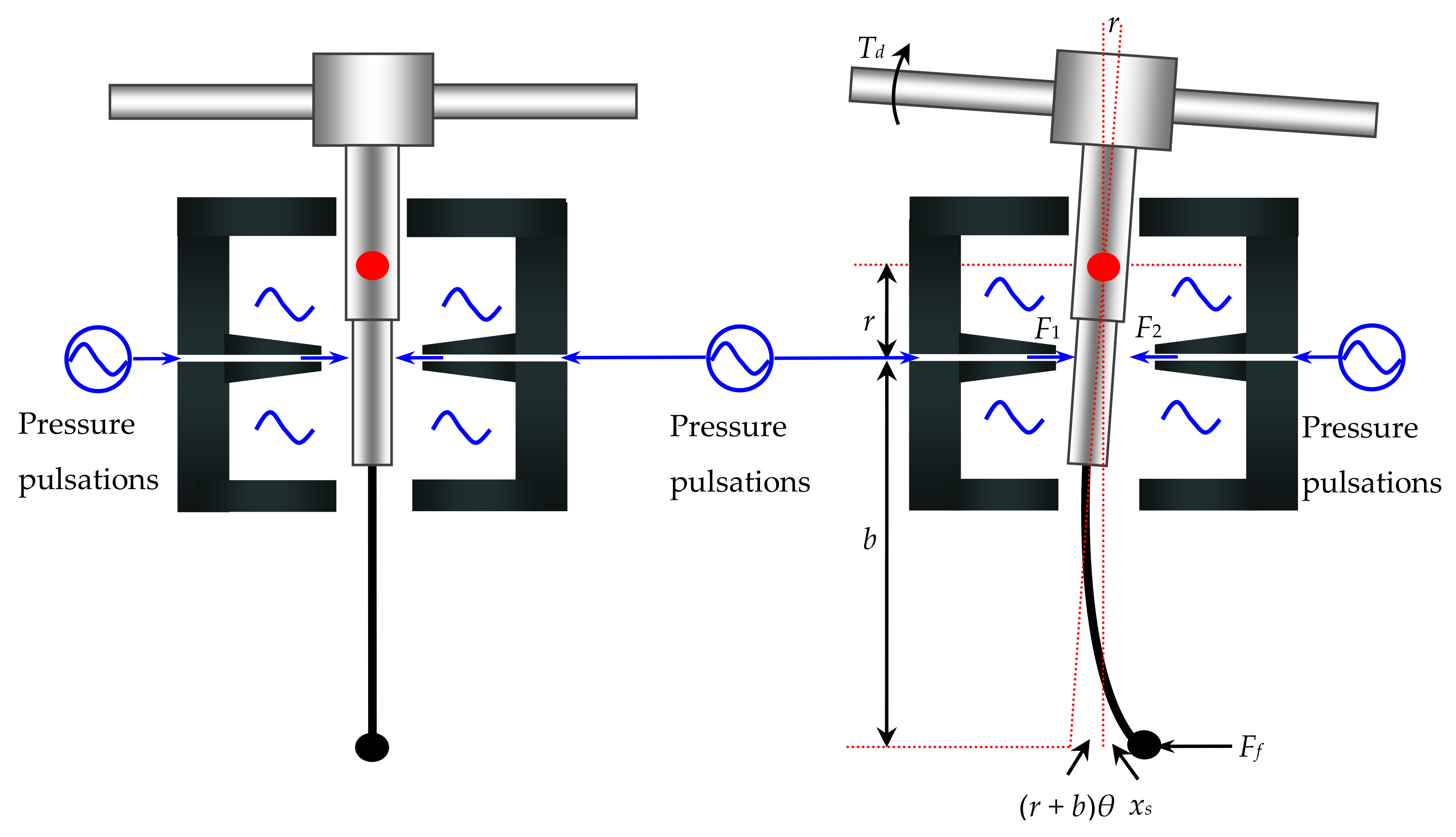
Figure 3.
Flapper-armature assembly: (a) 3D geometry model of the assembly; (b) meshed model and boundary conditions of the assembly; (c) assembly profile.
Figure 3.
Flapper-armature assembly: (a) 3D geometry model of the assembly; (b) meshed model and boundary conditions of the assembly; (c) assembly profile.

Figure 4.
The eight mode shapes of the Type A flapper-armature assembly: (a) First mode; (b) second mode; (c) third mode; (d) fourth mode; (e) fifth mode; (f) sixth mode; (g) seventh mode; (h) eighth mode.
Figure 4.
The eight mode shapes of the Type A flapper-armature assembly: (a) First mode; (b) second mode; (c) third mode; (d) fourth mode; (e) fifth mode; (f) sixth mode; (g) seventh mode; (h) eighth mode.

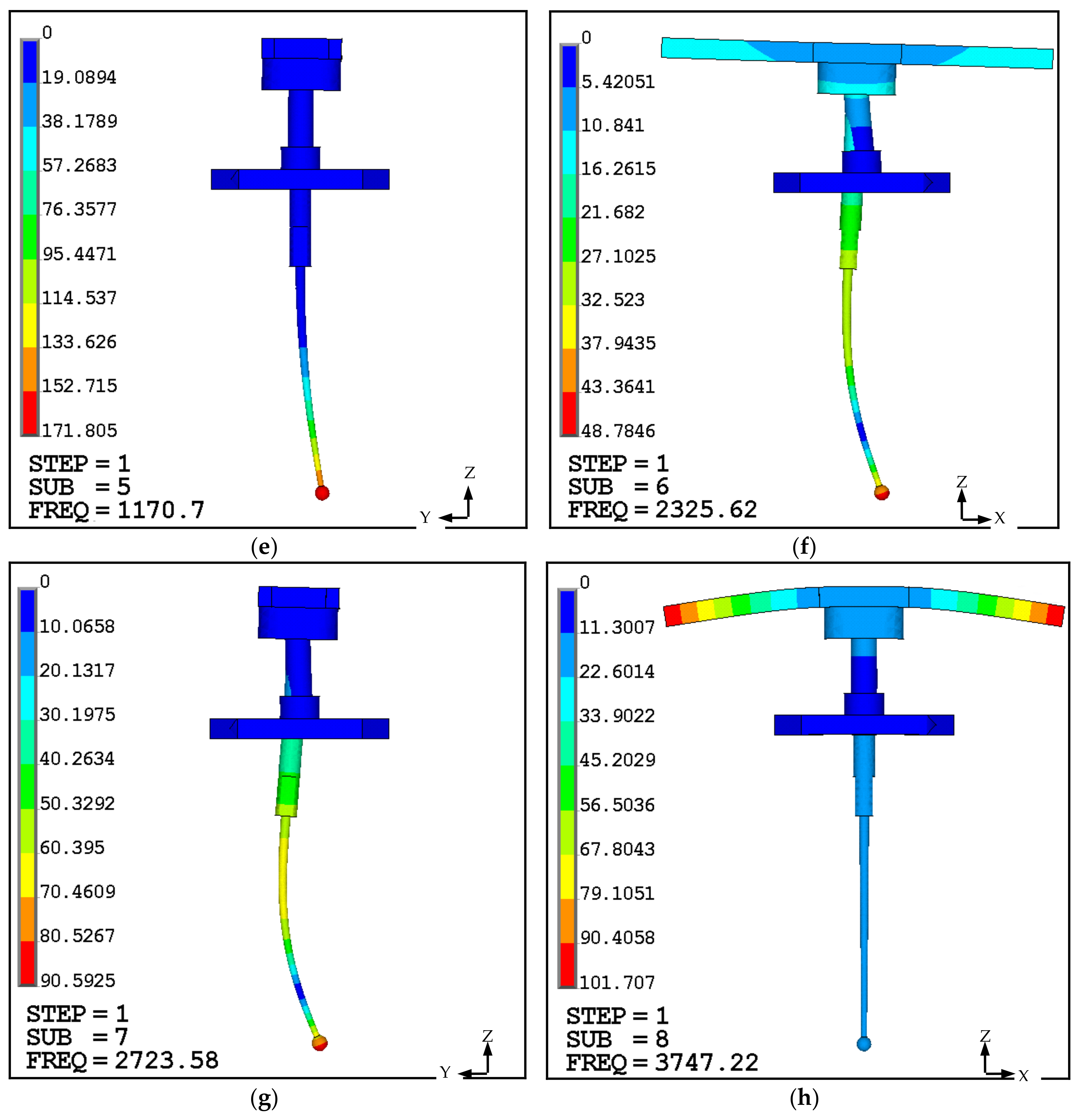
Figure 5.
The eighth mode shape of the Type B flapper-armature assembly.
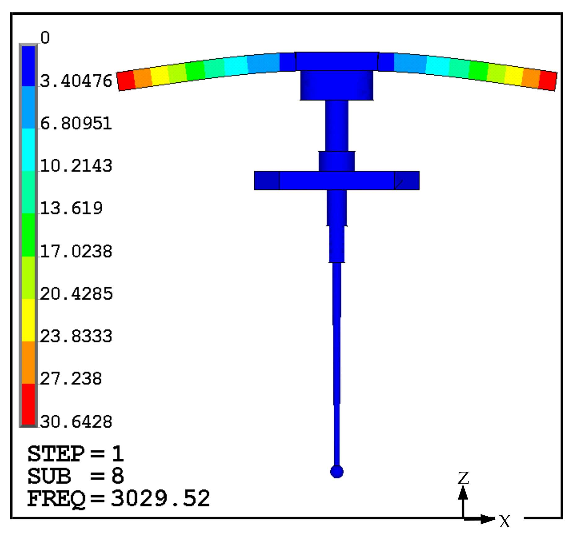
Figure 6.
Schematic diagram of the experimental setup: 1, Oil tank; 2, motor; 3, axial piston pump; 4, filter; 5, relief valve; 6, servo, valve; 7, throttle valve; 8, data acquisition board; 9, motor controller 10, computer; 11, piezoelectric pressure sensor; 12, pressure gauge; 13, laser displacement sensor; 14, piezoelectric microphone; 15, rotation speed sensor.

Figure 7.
Picture of the experimental measurement.

Figure 8.
Characteristics of the pressure pulsations at P1 for the Type A flapper-armature assembly: (a) in the time domain; (b) in the frequency domain.
Figure 8.
Characteristics of the pressure pulsations at P1 for the Type A flapper-armature assembly: (a) in the time domain; (b) in the frequency domain.

Figure 9.
Characteristics of the pressure pulsations at P2 for the Type A flapper-armature assembly: (a) in the time domain; (b) in the frequency domain.
Figure 9.
Characteristics of the pressure pulsations at P2 for the Type A flapper-armature assembly: (a) in the time domain; (b) in the frequency domain.

Figure 10.
Characteristics of the armature vibration for the Type A flapper-armature assembly: (a) in the time domain; (b) in the frequency domain.
Figure 10.
Characteristics of the armature vibration for the Type A flapper-armature assembly: (a) in the time domain; (b) in the frequency domain.

Figure 11.
Noise characteristics for the Type A flapper-armature assembly: (a) in the time domain; (b) in the frequency domain.
Figure 11.
Noise characteristics for the Type A flapper-armature assembly: (a) in the time domain; (b) in the frequency domain.

Figure 12.
Comparison of the primary frequencies between the calculated and experimental results for the Type A flapper-armature assembly.
Figure 12.
Comparison of the primary frequencies between the calculated and experimental results for the Type A flapper-armature assembly.

Figure 13.
Comparison of the amplitudes corresponding to the primary frequencies for the Type A flapper-armature assembly.
Figure 13.
Comparison of the amplitudes corresponding to the primary frequencies for the Type A flapper-armature assembly.

Figure 14.
Comparison of the primary frequencies between the calculated and experimental results for the Type B flapper-armature assembly.
Figure 14.
Comparison of the primary frequencies between the calculated and experimental results for the Type B flapper-armature assembly.

Figure 15.
Comparison of the amplitudes corresponding to the primary frequencies for the Type B flapper-armature assembly.
Figure 15.
Comparison of the amplitudes corresponding to the primary frequencies for the Type B flapper-armature assembly.


Table 1.
Material properties of the flapper-armature assembly.
| Group | Material | Young’s Modules (Pa) | Poisson’s Ratio | Density (kg·m−3) |
|---|---|---|---|---|
| Armature | 1J50 | 1.57 × 10¹¹ | 0.3 | 8200 |
| Spring tube | QBe1.9 | 1.25 × 10¹¹ | 0.35 | 8230 |
| Flapper and feedback rod | 3J1 | 1.9 × 10¹¹ | 0.3 | 8000 |
Table 2.
First eight order natural frequencies of the flapper-armature assembly.
| Mode | First | Second | Third | Fourth | Fifth | Sixth | Seventh | Eighth | |
|---|---|---|---|---|---|---|---|---|---|
| Frequency (Hz) | Type A | 489 | 554 | 690 | 1090 | 1171 | 2326 | 2724 | 3747 |
| Type B | 406 | 427 | 663 | 1072 | 1145 | 2132 | 2708 | 3030 | |
Table 3.
Properties of the hydraulic oil.
| Parameter | Density (kg/m3) | Viscosity (N·s/m2) | Surface Tension (N/m) |
|---|---|---|---|
| Liquid | 850 | 0.0085 | 0.0273 |
Table 4.
Detailed specifications and probable uncertainties in measuring devices.
| Devices | Specifications | |
|---|---|---|
| Axial piston pump | Rated supply pressure | 18 MPa |
| Rated flow rate | 20 L/min | |
| Pistons number | 9 | |
| Servo-valve | Rated current | 10 mA |
| Rated supply pressure | 21 MPa | |
| Rated flow rate | 20 L/min | |
| Laser displacement sensor | Model | LK-G5000 KEYENCE Co., Ltd. |
| Measurement range | ±3 mm | |
| Resolution | 0.01 μm | |
| Piezoelectric microphone | Model | 130E22 PCBPIEZOTRONICS Co., Ltd. |
| Sensitivity | 45 mV/Pa | |
| Phase match (5 kHz–10 kHz) | ±10° | |
| Piezoelectric pressure sensor | Model | 113B22 PCBPIEZOTRONICS Co., Ltd. |
| Maximum pressure | 34 MPa | |
| Nonlinearity | <1% | |
| Pressure gauges | Maximum pressure | 16 MPa |
| Uncertainty | <1.5% | |
| Data acquisition board | Model | NI cDAQ-9172 |
Table 5.
Comparison of the calculated and experimental primary frequencies for the Type A flapper-armature assembly.
Table 5.
Comparison of the calculated and experimental primary frequencies for the Type A flapper-armature assembly.
| Group | Motor Speed (Rev/min) | Frequency | ||||
|---|---|---|---|---|---|---|
| Equation (1) (Hz) | Pressure-A (Hz) | Pressure-B (Hz) | Vibration (Hz) | Noise (Hz) | ||
| N1 | 10,400 | 3120 | 3090 | 3104 | 3064 | 3092 |
| N2 | 11,400 | 3420 | 3382 | 3402 | 3378 | 3452 |
| N3 | 12,400 | 3720 | 3734 | 3726 | 3708 | 3724 |
| N4 | 13,400 | 4020 | 4042 | 4024 | 3992 | 4058 |
| N5 | 14,400 | 4320 | 4304 | 4326 | 4398 | 4314 |
Table 6.
Comparison of experimental results for the Type A flapper-armature assembly.
| Group | Primary Frequencies and Amplitudes | |||||||
|---|---|---|---|---|---|---|---|---|
| Pressure-A | Pressure-B | Vibration | Noise | |||||
| Frequency (Hz) | Amplitude (Pa) | Frequency (Hz) | Amplitude (Pa) | Frequency (Hz) | Amplitude (μm) | Frequency (Hz) | Amplitude (Pa) | |
| N1 | 3090 | 120,487 | 3104 | 85,835 | 3064 | 5.07 | 3092 | 0.26 |
| N2 | 3382 | 130,357 | 3402 | 92,764 | 3378 | 6.89 | 3452 | 0.35 |
| N3 | 3734 | 592,878 | 3726 | 889,317 | 3708 | 48.64 | 3724 | 2.96 |
| N4 | 4042 | 191,766 | 4024 | 143,612 | 3992 | 8.95 | 4058 | 0.58 |
| N5 | 4304 | 340,646 | 4326 | 252,543 | 4398 | 14.91 | 4314 | 0.92 |
Table 7.
Comparison of the experimental results for the Type B flapper-armature assembly.
| Group | Primary Frequencies and Amplitudes | |||||||
|---|---|---|---|---|---|---|---|---|
| Pressure-A | Pressure-B | Vibration | Noise | |||||
| Frequency (Hz) | Amplitude (Pa) | Frequency (Hz) | Amplitude (Pa) | Frequency (Hz) | Amplitude (μm) | Frequency (Hz) | Amplitude (Pa) | |
| N1 | 3198 | 118,364 | 3206 | 82,493 | 3190 | 4.35 | 3194 | 0.21 |
| N2 | 3386 | 134,612 | 3394 | 90,502 | 3390 | 6.14 | 3414 | 0.32 |
| N3 | 3742 | 160,457 | 3718 | 134,317 | 3736 | 7.82 | 3730 | 0.45 |
| N4 | 4040 | 186,391 | 4084 | 158,413 | 4052 | 9.27 | 4068 | 0.62 |
| N5 | 4328 | 325,489 | 4332 | 227,358 | 4364 | 12.08 | 4384 | 0.87 |
© 2018 by the authors. Licensee MDPI, Basel, Switzerland. This article is an open access article distributed under the terms and conditions of the Creative Commons Attribution (CC BY) license (http://creativecommons.org/licenses/by/4.0/).
Share and Cite
MDPI and ACS Style
Chen, M.; Xiang, D.; Li, S.; Zou, C. Suppression of Squeal Noise Excited by the Pressure Pulsation from the Flapper-Nozzle Valve inside a Hydraulic Energy System. Energies 2018, 11, 955. https://doi.org/10.3390/en11040955
AMA Style
Chen M, Xiang D, Li S, Zou C. Suppression of Squeal Noise Excited by the Pressure Pulsation from the Flapper-Nozzle Valve inside a Hydraulic Energy System. Energies. 2018; 11(4):955. https://doi.org/10.3390/en11040955
Chicago/Turabian StyleChen, Meng, Dong Xiang, Songjing Li, and Changfang Zou. 2018. "Suppression of Squeal Noise Excited by the Pressure Pulsation from the Flapper-Nozzle Valve inside a Hydraulic Energy System" Energies 11, no. 4: 955. https://doi.org/10.3390/en11040955
Note that from the first issue of 2016, this journal uses article numbers instead of page numbers. See further details here.