Digital Soft Start Implementation for Minimizing Start Up Transients in High Power DAB-IBDC Converter


School of Electrical Engineering, Pusan National University, Busandaehak-ro 63 Beon-gil 2, Busan 46241, Korea
*
Author to whom correspondence should be addressed.
Energies 2018, 11(4), 956; https://doi.org/10.3390/en11040956
Submission received: 2 April 2018
/
Revised: 12 April 2018
/
Accepted: 14 April 2018
/
Published: 17 April 2018
(This article belongs to the Section D: Energy Storage and Application)
Abstract
:The dual active bridge isolated bidirectional DC-DC converter (DAB-IBDC) is one of the prime converters used in dual active bridge renewable energy storage system (RESS) applications, particularly where a high-power density is required. The digital DSP (Digital Signal Processer) control technique also provides intelligence to applications and achieves a super compact elegant system by reducing the complicated control hardware. All power converters, including the DAB-IBDC converter, often draw an inrush current, which is many times higher than their steady state current. The inrush current is the maximum current drawn by a converter for a very few milliseconds while being freshly energized. Although it appears for only a very few milliseconds, it can cause severe damage to the entire energy storage system, including the sources and loads. To save the RESS system from the starting inrush current and peak overshoot voltages, this paper proposes a five-phase digital soft-start control algorithm for a high-power DAB-IBDC converter that was implemented at a renewable energy storage system aimed at developing an intelligent self-powered energy zone. The proposed five phase digital soft-start algorithm can alone solve the startup transients without the use of any additional hardware. First, it prevents the output current and voltages from transients, such as the inrush current and peak overshoot voltages, by ensuring that the output current does not increase too rapidly while starting up. Second, it also eliminates the large backflow inrush current released by a partially discharged energy storage device at the starting period. Third, it helps achieve a simple super compact size DAB-IBDC converter with a simple elegant design by ensuring the control and soft-start in digital technology.
1. Introduction
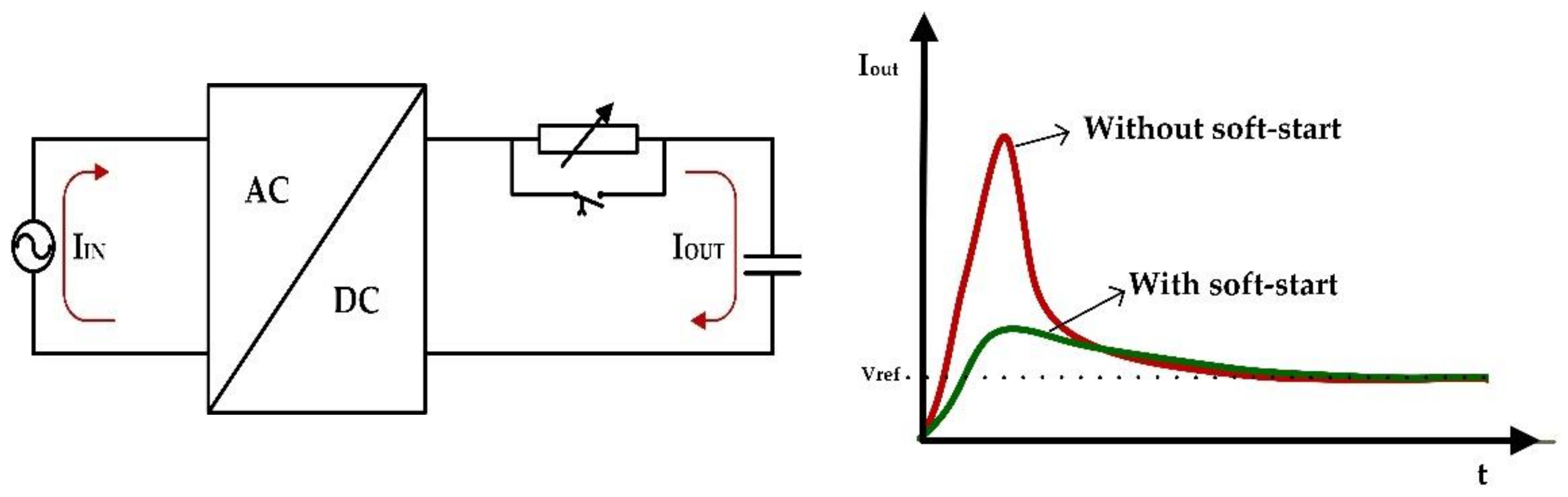
The inrush current or input surge current is the maximal large amount of current drawn by an electrical device while being freshly energized. This startup surge current exceeds the steady state current of the device [1,2]. For example, when electric motors and transformers are switched on, they may draw a large inrush current that is several times higher than the normal full load current, for a few input cycles and this can cause severe damage. Therefore, the inrush current must be avoided to achieve reasonable life cycles of an electrical device along with other safety features. In high power energy systems, it is strongly advised to remove the inrush current completely because it can affect the source and loads. Therefore, every high-power converter and inverter circuit is being designed with start-up topologies to avoid or reduce the inrush current [3,4]. In the below Figure 1, the given plot is shown that the inrush current effect at converter circuit in both cases that with soft-start and without soft-start.
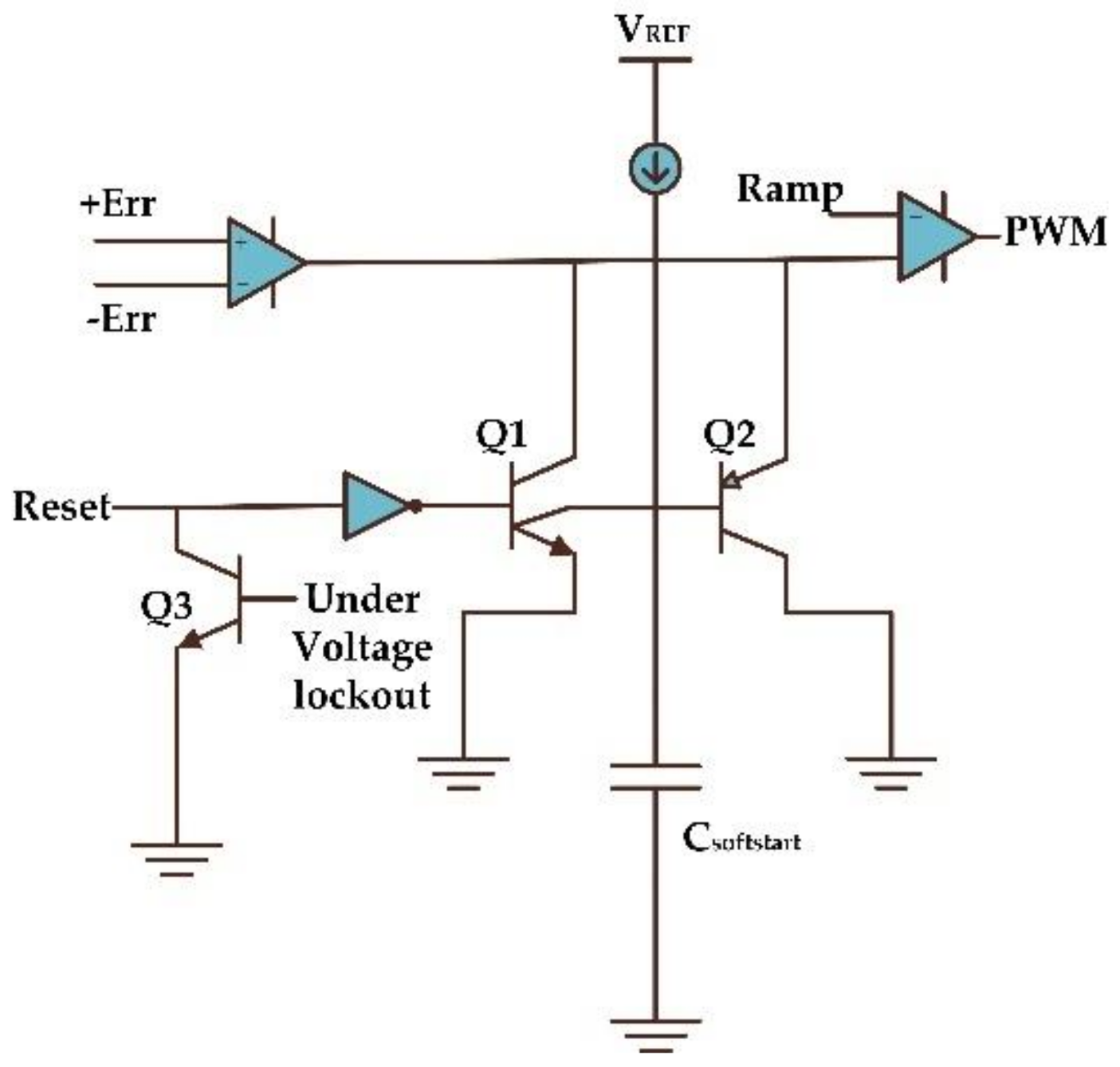
Almost all power converters contain in their designs large volume smooth capacitors and magnetizing components, such as transformers and inductors, which are principally associated with the inrush current and overshoot voltages. The entire power management system may be ruined because of the inrush current and a peak overshoot voltage appears, even for a few milliseconds during the startup period. The soft-start minimizes the inrush current in the circuit and later achieves a safe start-up; it then switches to the normal operation mode. Both analog and digital methods are currently used to build up the soft-start techniques. Analog soft starts can be implemented in various ways, either using discrete components [5,6] or integrated circuits (IC) [7,8]. The choice depends on the power rating of the power supply, which varies according to the application. The soft-start feature is commonly used in PWM (Pulse Width Modulation) controller ICs, which are currently available on the market, such as the UC1526, UC2526, TL594, LM5045, BM1P107FJ, and UC3526. This limits the inrush current and avoids the overshoot voltage at the output during start-up transients. For example, Figure 2 shows the PWM controller IC UC2526’s inbuilt soft start circuit. The circuit guarantees that the duty cycle is increased progressively at start up, which is employed upon first powering of the chip and enables a soft-start for the converter circuit.
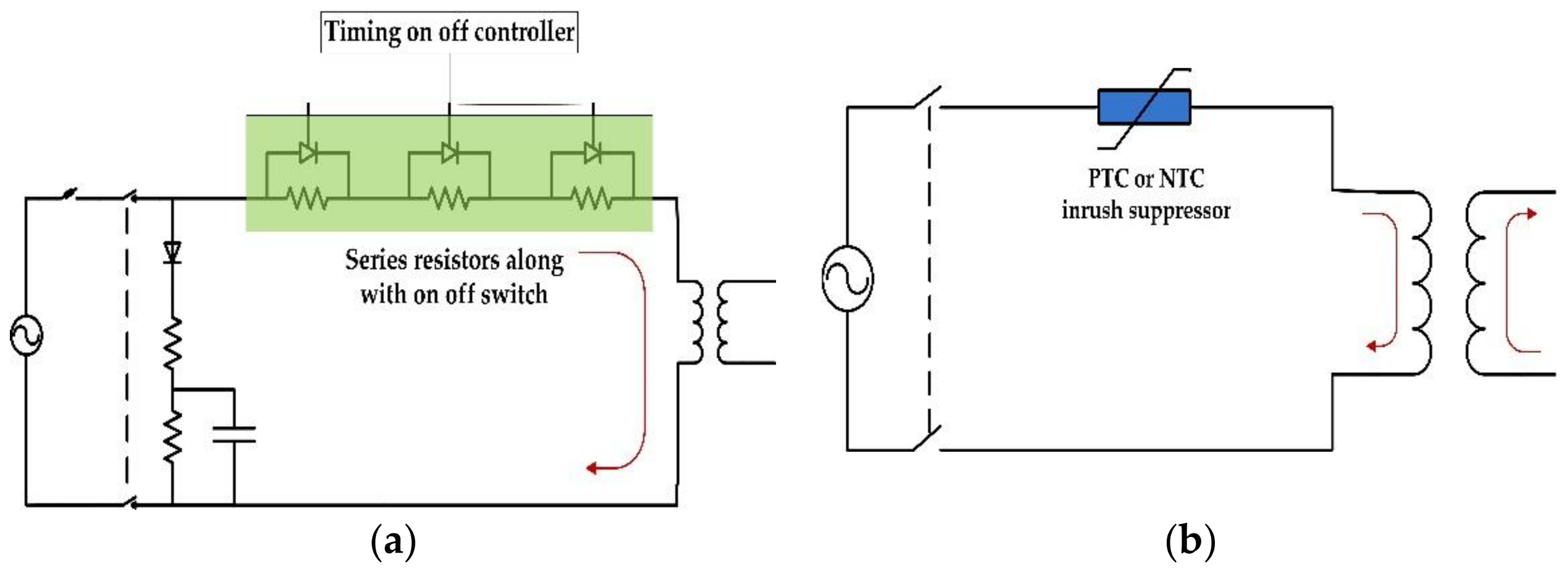
Figure 3 shows some traditional soft-start circuits, where the soft-start is implemented using discrete components. Usually, during start-up, high resistive devices are added temporarily to the circuit for a short duration, which is shown in Figure 3a. This provides high resistance to the starting current and minimizes the inrush current and peak overshoots at the output. However, the circuit sizes are more complex and losses high at this resistive soft-start method. In order to achieve soft-start with simple design, thermometric devices were proposed, such as resettable PTC (Positive Temperature Co-efficient), a NTC (Negative Temperature Co-efficient) inrush suppressor which shown in Figure 3b. If a power failure does occur, however, the device might be unstable and cause problems, and the power returns before the device has cooled sufficiently to achieve its high resistance. Therefore, applying a universal soft-start solution across multiple applications would be extremely challenging.
This study developed a self-powered energy zone that consists of renewable energy sources and energy storage systems. The self-powered energy zone called the no grid power zone depends entirely on renewable energy sources, such as solar, wind, and fuel cells [9]. The authors are developing a standalone renewable energy storage system that combines a high power solar module with hybrid energy storage systems, which is a combination of super capacitors and batteries. A high power dual active bridge isolated bidirectional DC-DC converter (DAB-IBDC) converter was developed as an intermediate circuit between renewable energy sources and hybrid energy storage systems [10]. Many DC-DC converter topologies have been proposed for standalone renewable energy storage system applications with the aim of achieving the maximum power density, maximum conversion efficiency, and secure rapid charging-discharging [11,12,13,14]. Based on reviews, among all the DC-DC converters, the DAB-IBDC converter provides an attractive solution by interconnecting different DC buses, particularly where a high power density with higher efficiency is required. Among the many researchers in the dc power conversion field, DAB-IBDC topology is the most popular converter because of its galvanic isolation, bi-directional power flow ability, buck/boost capability, high efficiency, handling high power density, and inherent soft switching property [15,16,17,18]. Moreover, it can be used in a wide range of applications, such as photovoltaic systems, energy storage systems, electric vehicles, renewable energies integration, and avionics applications.
On the other hand, as with other topologies, soft-start inrush current issues are also the main drawbacks of this topology. The starting inrush current in DAB-IBDC converter cannot be determined by the controlled phase shift because it is directly proportional to the equivalent input voltage [19]. The starting process with a high input voltage and zero output voltage is not recommended in high power and high voltage applications because of the starting inrush current, which causes severe damage [20]. On the other hand, In ESS applications, energy storage systems perform reliably when freshly charged; hence, there is a fraction of full capacity unable to support a high starting inrush current [21]. Therefore, additional soft start circuits or soft start control algorithms are required to minimize the effects of the inrush current in the DAB-IBDC converter which implemented in ESS applications [22,23]. As digital soft-start techniques have attracted increasing attention in power converters [24,25], this paper focuses on a digital soft starting method for the DAB-IBDC converter to eliminate the huge, unacceptable, and potentially harmful currents experienced during start-up. In this study, a novel five phase digital soft-start algorithm for the DAB-IBDC converter was developed. The developed algorithm achieved a rapid soft-start with fast response and avoided the inrush current and peak overshoot voltages at the output of the converter.
In [26], Choi et al. proposed a soft-start algorithm to address the problem of the inrush current during cold start state in DAB converter. The algorithm is divided into three sequences (OPDC, OLPSC and CLPSC) in terms of output voltage level. The control algorithm suppresses the inrush current according to the output voltage level. The novel soft start two phase strategy was proposed in [27]. This can be designed especially for double source applications, where an inverse inductor current must be avoided. The soft start function uses subtractive type and time average capacitor multipliers has been described in [28]. This subtractive type soft-start helped much to relax the restrictions of the capacitance and the charging current. The soft start capacitance can be integrated easily into a chip and the overshoot voltage can be suppressed. In [29], Kurokawa et al., proposed a new digital load dependent soft start for a DC-DC converter in energy storage system applications. This prevents the negative effect in a power supply. The speed of the soft start is dependent on the load condition. In [30], Zhu et al. invented a product for reducing the inrush current in a high power isolated full bridge boost DC-DC converter. Here, a primary circuit with a clamping switch or at least two choke diodes, which include push pull and L type configurations and resistors, was used to dissipate the energy clamped from the voltage spike. Kurokawa et al. proposed an exponential function-based soft-start [31] and a linear function-based soft-start [32] and discussed how to change the speed of the soft-start operation depending on the load current. They could improve the soft-start characteristics compared to the conventional method, but they could not improve the performance in a wide range of load conditions.
This paper proposes a five-phase digital soft-start algorithm for a DAB-IBDC converter in RESS applications. The proposed five-phase digital soft-start algorithm can alone minimize the inrush current and peak over shoot voltages in the DAB-IBDC converter without being supported by any additional hardware. The proposed algorithm was verified at the DAB-IBDC converter with various power ratings (500 W, 1.5 kW, and 2.5 kW) and verified at different loads, such as non-linear ESS (supercapacitor) and linear-resistive loads. The proposed five phase digital soft-start algorithm working principle and concept are described in Section 2. The implementation of the soft-start in TMS320F28335 DSP is described in Section 3. The experimental setup is outlined in Section 4 and the results and discussion with detailed explanations are given in Section 5.
2. Digital Soft Start Theory for DAB-IBDC Converter
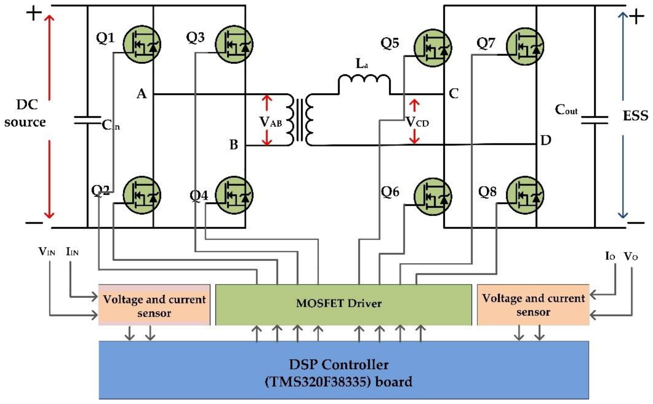
A DAB-IBDC converter consists of two full bridge circuits isolated by a high frequency transformer with a leakage inductance, as shown in Figure 4. A renewable DC energy source and load was connected to the primary side and the energy storage system was connected to the secondary side of the converter. Each bridge consists of four MOSFET switches that are controlled by PWM signals to provide a DC bus square wave voltage. These two bridge DC square waves can be suitably phase shifted with respect to each other to control the power flow from one side to the other. In the forward mode or buck mode of operation, the phase of the secondary square wave (VS) is shifted by the primary square wave (VP) and achieves power flow from the primary to the secondary side. In backward mode or boost mode of operation, the power flow achieved in the reverse direction by the set phase of the primary square wave (VP) is shifted by the secondary square wave (VS). Both digital and analog control methods are being developed to control the DAB-IBDC converter. In this study, the digital control method was selected because of its accessible wide bandwidth applications and designed digital control DAB-IBDC converter.
The DAB-IBDC output waveform is periodic over a half cycle. Thus, dividing the area by the duration Ts/2, the average output current of the DAB converter:
Normally the average output current depends on :
From Equation (2), by substituting full control range 0~1 to the phase shift d, it can be observed that maximum power transfer occurs for a duty ratio of 0.5. The total transmission power and backflow power can be derived as follows:
where, n = transformer turns ratio, k = voltage transfer ratio, d-phase shift between Vab and Vcd, Vin = input voltage, Vout = charging voltage, L = inductance of a converter, Ts = switching time.
With increasing backflow power, the forward power also increases to compensate for the loss caused by backflow power. The circulating power and current stress are then increased, which result in great loss in power devices and magnetic components and low efficiency of the converter:
The high frequency-high power density DAB-IBDC topology is made up with the prime energized components, such as coupling capacitors, inductor, and high frequency transformer, which are principally associated with the inrush current and over shoot voltage. Moreover, in Figure 4 the DC and ESS side terminals are provided with rather large capacitors which will cause inrush currents to appear. When the power is first applied to the converter, the capacitors must be charged from zero to their final values while the transformers and inductors need to have their flux stabilized. Similarly, the other active components and integrated circuits in a converter must be changed from the inactive states to active states. At this circumstance, the control algorithm is not determined by the starting current but by the peripheral circuit. Since the transformer secondary voltage is zero, the maximum current appears at the starting period:
Therefore, the input impedance of the converter is very low during startup which causes a large inrush current flow into the circuit when freshly energized. As the large inrush currents are many times greater than the DAB-IBDC converter steady state current, they can easily damage the converter components by increasing the stress and causing short circuits. This may also affect the main power supply sources along with converters. The proposed five phase digital soft-start algorithm aims to minimize the inrush current in a DAB-IBDC converter without adding any additional circuits and resistive devices. This turns on the converter with a controlled time delay that gradually increases the startup current at a slower rate from zero to the required value. It ruptures the initial startup process into five phases and provides a controlled time delay in each phase according to the principle of the DAB-IBDC topology. The time delay ranges, which lie between few micro seconds to milliseconds, depend the power ratings of the converter circuit and load. The proposed five phase digital soft-start algorithm ensures that the desired output voltage and current is achieved without stressing the components placed in a DAB-IBDC converter circuit. This allows the transformer and inductors to overcome the steadied flux, the capacitor to charge the desired output voltage, and all integrated ICs to change their states from inactive to active at a safe pace.
In the normal mode of operation, the primary and secondary bridge are both operated with the same frequency and 50% duty pulse width. The PI controller controls the phase shift between the primary and secondary bridge square wave voltage to achieve the proper line regulation with a valid output voltage. When newly energized, however, the circuit is damaged in normal operation mode because of the starting inrush current. For example, exceeding a MOSFET current rating for a few milliseconds is sufficient to destroy it. Therefore, before switching to the normal operation mode, a soft start mode is necessary to prevent circuit from damage. The proposed digital control algorithm introduces five phase of operation as a soft start algorithm before switching to the normal mode of operation. Each phase works towards increasing the output current progressively with different time durations based on its own principles. This step by step five phase soft start process decreases the inrush current and helps achieve the required output nominal voltage at a safe pace. Once it reaches the nominal output voltage, the algorithm then switches the process from a soft-start mode to normal mode of operation. The five-phase digital soft-start algorithm is given below with a detailed explanation of each phase:
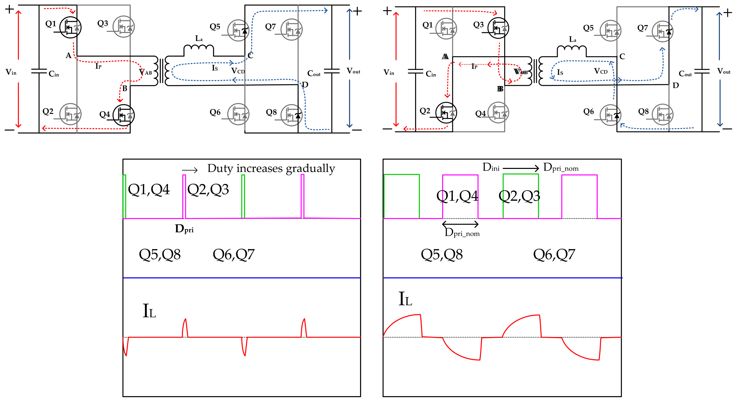
Phase A: In five-phase soft-start mode, phase A is the initial state of process. The duty cycle of the primary bridge PWM signals is increased from a relatively small value (Dini) to the prime nominal value (Dpri_nom) at a linear and minimum rising rate by keeping the secondary bridge switches OFF. The initial duty Dini value has been set by the controller itself based on the initial voltage of the energy storage system or output capacitor. The PWM duty is increased progressively until the output current reaches the steady value and that duty value is set to Dpri_nom. In the N-channel enhancement MOSFET (Metal Oxide Semiconductor Field Effect Transistor), the current can typically flow in both directions from the drain to the source and vice versa when the gate channel be triggered properly. Owing to the internal body diode polarity, the current can still flow from the source to drain even the MOSFET in the OFF state or the gate channel is not induced. In phase A, even the secondary full bridge is OFF; this conducts the current due to the body diode of the MOSFET, which acts as full bridge diode, as shown in Figure 5.
Phase B: Phase B is the second stage process of the soft-start algorithm, where the secondary bridge PWM square wave VCD duty cycle is increased progressively from a zero duty to the maximum nominal duty (Dnom), i.e., a 50% duty cycle. During the entire process, the primary bridge PWM square wave duty is maintained at Dpri_nom, which was set at end of the previous phase A. The current flow path for phase B is given in Figure 6, which appears to be like the phase A current flow. On the other hand, because the MOSFET was triggered, the current flows into the switches instead of the body diode and increases the output current slightly. In phase B, the output current increases at a lower rate because the voltage difference across the inductor decreases with increasing secondary side average dc square wave (VCD) voltage. Therefore, the phase B process time duration can be set by the controller much faster than phase A because the output current increases at a lower rate. Phase B process is also considered as the time delay zone which provides sufficient delay and waits to rise the output current sufficiently after the phase A process is complete.
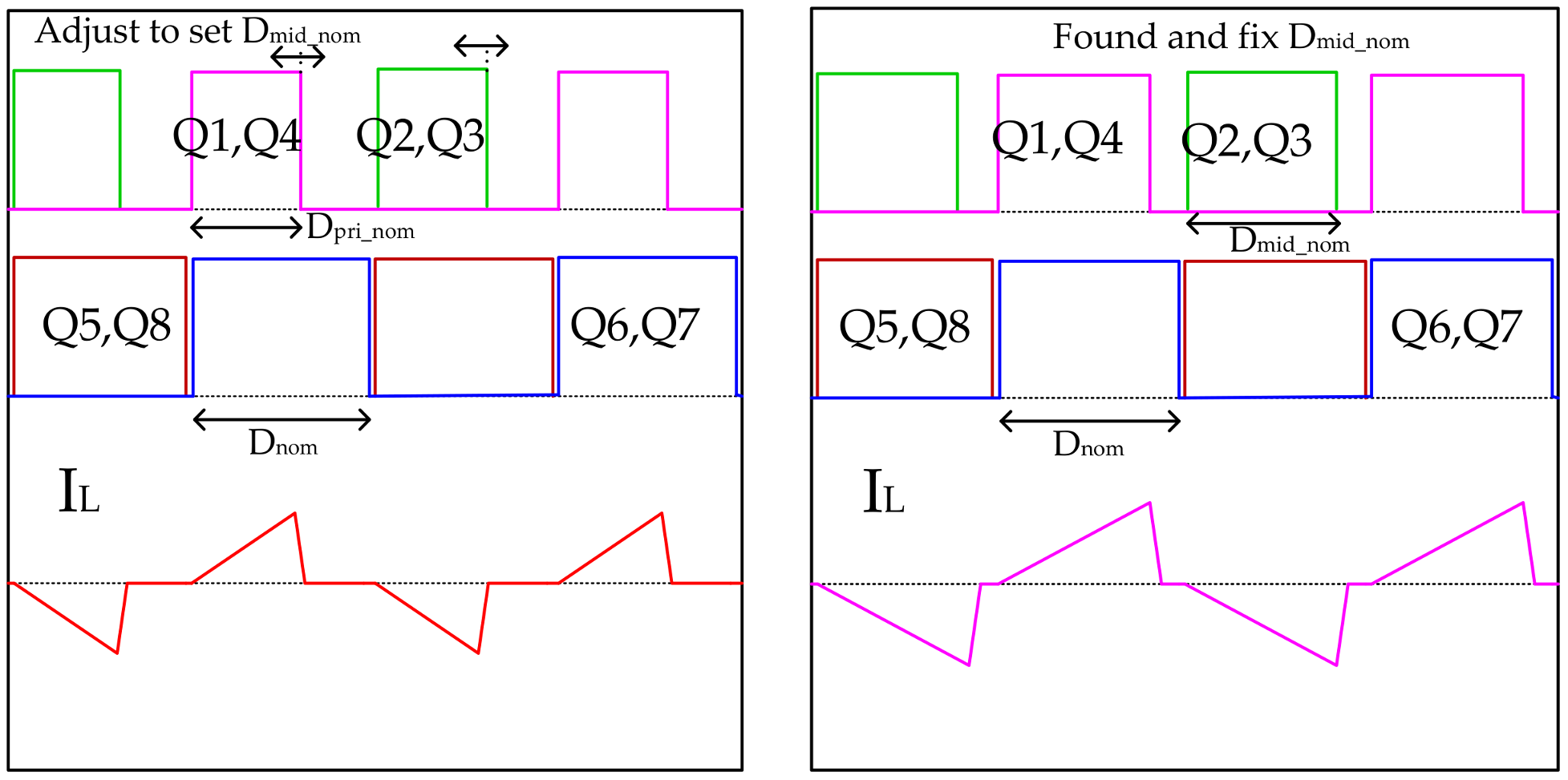
Phase C: The Phase C process is started as the third stage of the soft-start algorithm after the secondary bridge PWM duty is reached by Dnom at the end of the phase B process. In this phase C, the secondary bridge PWM is maintained at Dnom and the Primary bridge PWM square wave duty adjusts to reach Dmid_nom from Dpri_nom based on the output voltage/current feedback signals. The Phase C stage helps increase the output current linearly with help of the gradually increasing duty Dpri_nom. Fluctuations occur in the output current when an increasing duty output current rises to a particular duty value called Dmid_nom. The digital controller senses this fluctuation through the feedback signal and stops increasing the duty value at Dmid_nom and sets this value as the duty cycle. The phase C increases the primary PWM square wave duty as much as possible before applying the phase shift between the primary and secondary PWM square waves at Phase D. The primary and secondary PWM signals with respective inductor current at initial and end stage of the Phase C process are shown in Figure 7.
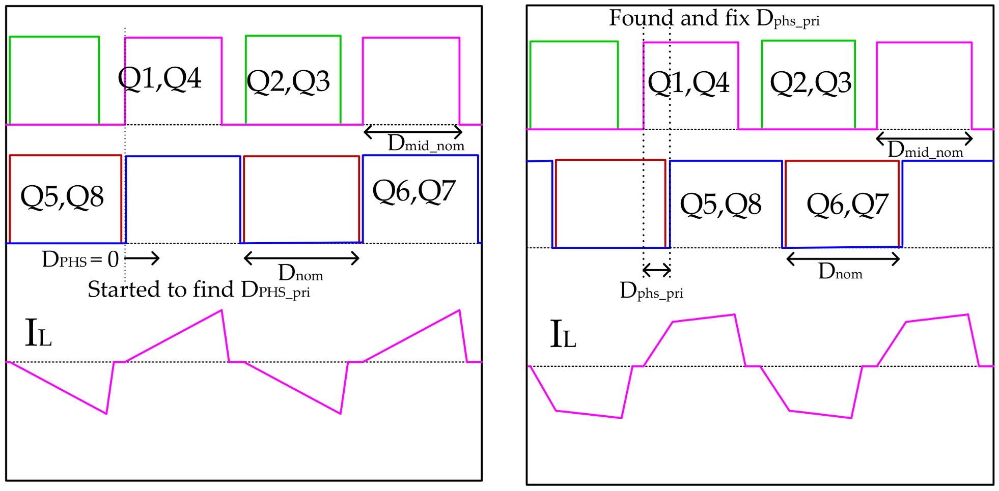
Phase D: This is the fourth stage of the soft-start process. In this phase D, during the whole process the primary and secondary bridge PWM signals maintain the same duty value Dnom and Dmid_nom, set by the end of the previous stage phase C. The phase shift between the primary DC square wave voltage and secondary DC square wave voltage are maintained at zero until the third stage phase C. In phase D, the output current progressively raised through increasing the phase shift between the two square waves at slow raising rate until DPHS_PRI. In most cases, before reaching DPHS_PRI, the output reaches its threshold value and passes over to the next stage. Initially the primary phase shift DPHS_PRI and frequency were set by the designer based on the review studies, and other converter specifications were designed through this. Although the duty shift is introduced, the DAB-IBDC converter does not begin to work in the normal mode because the primary PWM duty is not at the nominal range and the PI controller also off. Therefore, phase D is called the partial normal operation mode. The primary and secondary PWM signals with respective inductor current at initial and end stage of the Phase D process are shown in Figure 8.
Phase E: After introducing the phase shift in phase D, Phase E is started as the final stage of the soft-start controller algorithm. The primary bridge duty shift increases rapidly to Dnom and waits for a small period for the output voltage/current to reach its threshold value. This then switches to normal operation mode once the output has reached its threshold value. In normal operation mode, the PI controller is introduced to achieve a steady state error that controls the output current and voltage by varying the phase shift (DPHS) between the two square wave voltages. If the output threshold cannot be achieved, even by phase E mode, it will stop the converter process and the error signal will be given to the users. Figure 9 shows the PWM square wave signals and respective inductor current for phase E.
3. Digital Soft Start Implementation in DSP Controller
The digital control board was designed using a DSP (TMS320F28335) IC (Texas Instruments, Dallas, TX, USA) along with many analog subcircuits, such as isolation, filters, amplifiers, short circuit protection, temperature protection, PWM protection, and voltage and current sensing circuits. This receives a feedback signal from the DAB-IBDC converter and processes it using a high performance CPU. The board then generates a controlled PWM signal based on the control algorithm. The TMS320F28335 device is a member of the TMS320C28x/Delfino™ DSC/MCU generation (Texas Instruments, Dallas, TX, USA), highly integrated, high-performance solutions for demanding control applications. This is a very efficient C/C++ engine, enabling the users to develop their system control software in a high-level language. This device also enables math algorithms to be developed using C/C++. The device is as efficient as the DSP (Digital Signal Processor) math tasks because it comprises system control tasks that are typically handled by microcontroller devices. The designed DSP digital control board shown in Figure 10 can access the eight PWM signal port, six ADC (Analog to Digital Converter) port, and six other GPIO (General Purpose Input/Output) ports. The six feedback input signals are converted to a low voltage or DSP accessible voltage range (0 to 3 V) by isolated voltage-current sensing circuits before being applied to the controller ADC port. The feedback signals are processed by the CPU unit based on the control algorithm and the corresponding PWM signals are produced at the PWM port. In addition to the ADC, PWM port, some of the GPIO ports can be accessed with this design, which is mainly associated with additional protecting devices, such as controlling relays, programmable fuses, and monitors. The DC supply with various voltage ranges, 5 V, 15 V, and ±24 V, are needed for biasing the digital controller board along with subcircuits.
Figure 11 presents a flow chart and waveform timing diagram for the proposed five phase digital soft start algorithm. The soft-start process is started before commencing the normal operation mode when the circuit is first energized. The output voltage and current are sensed and fed to the DSP controller through isolated sensing circuits. The ADC module samples these feedback signals and converts them to the respective digital signals. The isolated voltage and current sensing circuits provide the isolation between the high-power converters and low power digital control board. Through isolation, common grounding between the high voltage converter and low voltage control circuits can be avoided, which enhance the additional protection to the digital controller board. The output voltage and current compared to its respective threshold value (VTH and ITH) is commonly set to 90% of the required output value, where the chances of transient occurrence are completely avoided. The five-phase soft-start process will be started and increases the output gradually to its threshold level without transients. The output voltage and current are always monitored and validated during the entire soft start process. If either VO or IO reaches the threshold level during the mid of the soft-start process, the soft start mode stops suddenly and switches to normal mode without continuing the remaining phases of the soft-start control algorithm.
Figure 11b presents the waveform timing diagram for the five-phase soft-start algorithm, which started with the off-state mode and ended with the normal operation mode. The controlled output current waveform during the soft-start process for each five phases are exposed separately in the given timing diagram. Each five phases help increase the output current gradually without an inrush current and peak over shoots. Because the converter has very low impedance at the starting duration, it is more likely to cause an inrush current, so the first phase time duration is slightly higher than all the other phases. In first phase, the average low input voltage is initially applied to avoid starting the inrush current, once the output capacitor reaches the minimum charge, the output current increases gradually to threshold level through help of the other phases. A soft start-enabled flag is used to allow a soft-start. This then operates the converter either in soft-start mode or normal mode. During the soft-start process, the phase-enabled flag is used to enable any one of five phases at one time. Using this, it can stop the process at the mid stage of any phase and can switch over to any other forward phases. Figure 11 shows the primary bridge square wave voltage duty cycle, secondary bridge square wave voltage duty cycle, and phase shift between the two square wave voltage waveforms for each phase of soft-start mode operation.
The TMS320F28335 DSP controller contains a 12-bit ADC module, which can auto sequence a series of conversions that perform multiple conversions automatically in the single start of a conversion request. In the designed DAB-IBDC model, four feedback signals, Vin, Vout, Iin, and Iout, are applied to the ADC as a feedback signals. Four input channels can be selected through the analog mix sequentially and after conversion, the respective digital values are stored in the appropriate result registers. The ADC module is operated in oversampling mode that samples the same signal multiple times and over writes the conversion results continuously by the main process. The ADC routine is programmed into TI-reserved OTP memory by the factory. The boot ROM automatically calls the ADC routine to initialize the ADCREFSEL (ADC Reference Select Register) and ADCOFFTRIM (ADC Offset Trim Register) registers with the device specific calibration data. During normal operation, this process occurs automatically, and no action is required by the user.
An effective PWM peripheral can generate complex pulse width waveforms with minimal CPU intervention. The PWM output signals are made available to an external device through the GPIO peripheral. The synchronization signals daisy chain the ePWM modules together. Each ePWM module has its own time-base submodule that determines all the event timings for the ePWM module. The counter-compare submodule compares the CMPA and CMPB registers with the time-base counter value. When the time-base counter is equal to one of the compare registers, the counter-compare unit generates an appropriate event. Based on this event, the action qualifier submodule controls the output PWM signals. The action-qualifier submodule considers the control direction either up or down and allows for independent output action. If changes in the CMPA (Counter Compare A register) and CMPB (Counter Compare B register) value alter the duty cycle of the PWM signal, a phase shift is provided through the PHS register for each PWM module.
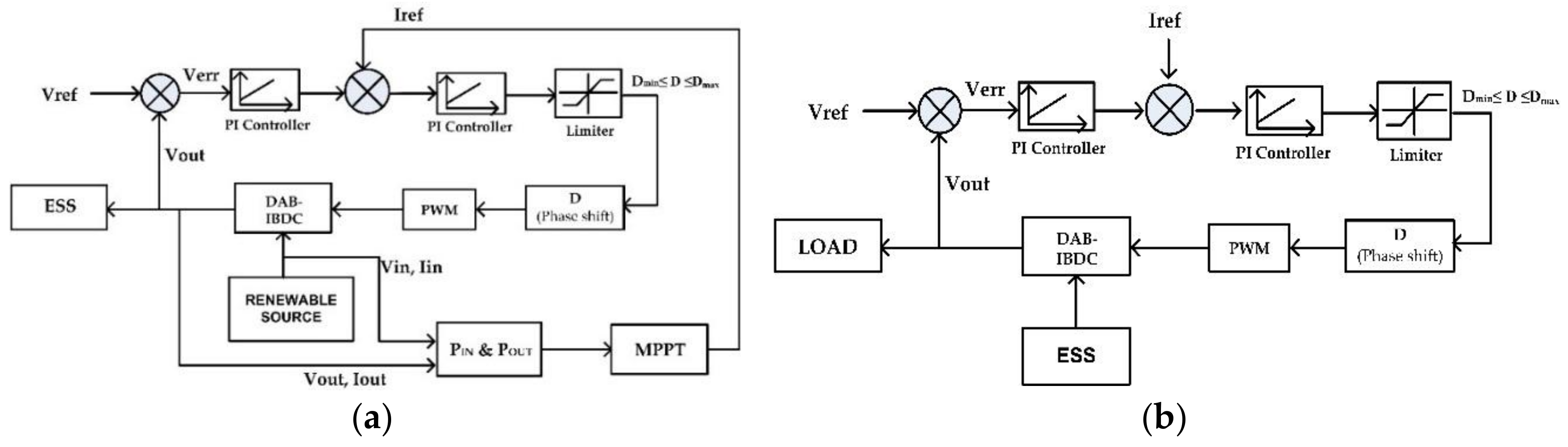
Figure 12 shows the single-phase shift and maximum power point digital control loop. The digital proportional integral (PI) controller has been designed to achieve a zero-steady state error in DAB-IBDC topology by finding the proper phase shift angle between the primary and secondary square waves. In the feedback loop, we have voltage PI controller loop as an outer loop and current PI controller loop as an inner loop. In the forward mode of operation, Voltage PI controller gives control value based on the error voltage (VErr) between reference value (Vref) and feedback voltage (Vfeed). Inner Current PI controller loop generates the control value based on the error voltage between voltage PI controller value and MPPT algorithm value (Iref). Parallelly the MPPT algorithm receives the input voltage-current, output voltage-current as feedback signals and processed it based on the MPPT algorithm. It finds the current reference and send to the inner current loop routinely. The required phase shift value (D) is generated by current PI controller and controls the DAB converter output towards achieving steady state error. These output signals fed back to the voltage PI controller as a feed-back signals. In the backward mode of operation, ESS discharging through the load and current flow is straight opposite to the forward mode current flow direction. As MPPT algorithm not needed in the discharging mode, Vref and Iref set by the designer and backward control loop is performed based on the same inner and outer loop. PI controller feedback loop sets the phase shift angle towards achieving steady state error for the backward power conversion.
The digital PI controller is given by:
PI_out = Pre_PI_out + Err × (Kp + 0.5 × Ki × Ts) + Pre_Err × (0.5 × Ki × Ts − Kp)
- Err = Ref−Variable
- Pre_Err = previous Err value
- Pre_PI_out = Previous PI_out value
- Kp—Proportional controller gain, Ki—integral controller gain.
4. Experiment
Figure 13 shows the developed DAB-IBDC converter circuit along with the experimental setup. In DAB-IBDC topology, each active bridge is designed with four power MOSFET switches. In the current design, the IXFK64N50P N channel enhancement power MOSFETs, which consist of an internal avalanche-rated fast intrinsic diode are used. According to the IXFK64N50P datasheet, the maximum drains source voltage can be 500 V and the maximum drain current is 64 A. The internal resistance is 85 mΩ and the maximum drain pulse current is 150 A. To trigger the MOSFET switches at high frequencies (f > 20 kHz), a ±6 to ±30 voltage with a 10 mA current need to be applied across the gate terminal. The MOSFET driver was designed with a FOD3180 opto-coupler (Fairchild semiconductor corporation, Sunnyvale, CA, USA) to drive the MOSFET switches with the required voltage and current. This receives the control low voltage PWM signals from DSP and boost it up to the required gate source (VGS) voltage of MOSFET. The designed MOSFET driver provides noiseless PWM signals and isolation between the power switches and DSP controller. The required inductance for the power conversion is shared by the secondary leakage inductance of the transformer and auxiliary inductance, which is provided by the additional inductor connected series with the secondary side of the transformer. The proposed five phase soft-start controller was verified using the designed DSP control DAB-IBDC converter with various power ratings, such as no load, 500 W, 1.5 kW, and 2.5 kW.
The input source of the DAB-IBDC converter was a 300 V renewable solar energy DC source, which was obtained from eight 38 V, 340 W solar panels connected in series. The output was connected to a supercapacitor bank, which was constructed with three 48 V, 165 F, and 53 Wh Maxwell supercapacitors connected in parallel. The overall supercapacitor bank specifications were 48 V, 495 F, and 159 Wh. Supercapacitors complement the primary energy source that cannot provide quick bursts of power repeatedly, such as an internal combustion engine, fuel cell or battery. The future horizon appears brilliant for supercapacitors, which already rank as a powerful alternative energy resource. The proposed DAB-IBDC converter was controlled by the digital control board, which was designed using a DSP (TMS320F28335) IC along with many subcircuits. Table 1, Table 2 and Table 3 list the DAB-IBDC converter specifications for 500 W, 1.5 kW, and 2.5 kW, respectively. The converter specifications for different power ratings are the same except for the inductance of the circuit. Therefore, various auxiliary inductors were designed with different values, 12.3 µH, 2.8 µH, and 1.1 µH, and added to the converter circuit to achieve the required power ratings for the DC conversion.
5. Results and Discussion
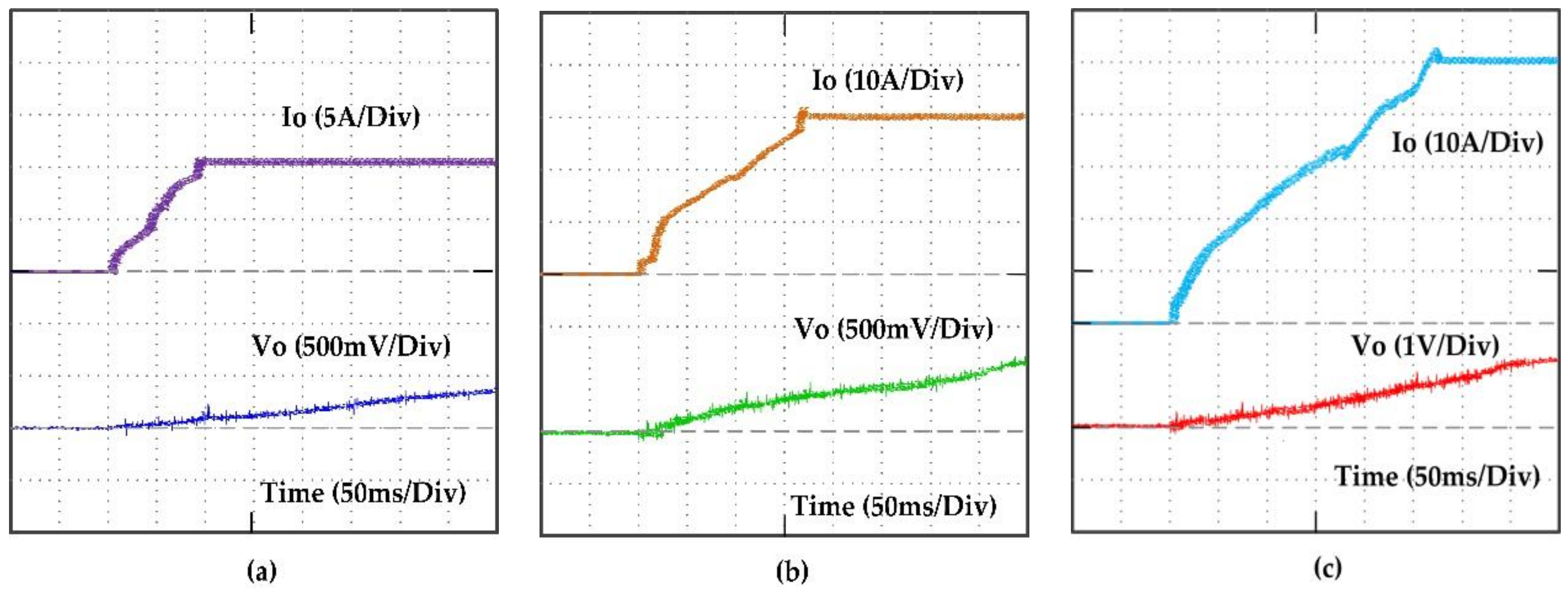
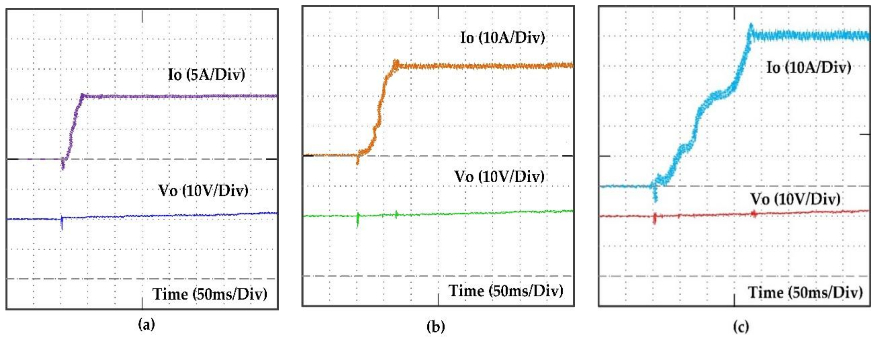
A supercapacitor bank (159 Wh) was connected to the converter output side and the experiment was conducted for different power ratings, 500 W, 1.5 kW and 2.5 kW. First, the initial charged voltage of the super capacitor bank was maintained at a zero voltage and the proposed five phase digital soft-start algorithm was verified at the DAB-IBDC converter with the stated three different power ratings. Figure 14a–c present the experimental results for three power ratings, 500 W, 1.5 kW and 2.5 kW, respectively. The supercapacitor charging voltage and current are plotted during the soft-start region. In this case, the five-phase digital soft-start algorithm achieved a steady state response by minimizing the inrush current and peak overshoot voltage at the output. The speed of the soft-start controls, or timing response was varied automatically to avoid the inrush current at various power ratings. The 500 W, 1.5 kW, and 2.5 kW DAB-IBDC converter reached a steady state current in 93, 167 and 274 ms, respectively.
On the other hand, the supercapacitor bank or battery bank using the renewable energy storage application cannot be discharged completely or until a zero voltage. Some of the voltage drop is always there and cannot be used by the load called the ESS terminal voltage. Therefore, keeping some of the terminal voltage, if an attempt is made to charge it again, a sudden back current flow will rise and a peak overshoot will occur; the energized components, such as the transformer and inductor, gain more stress and can be damaged instantly. Therefore, the designed soft-start controller also must concern the initial charging voltage of the energy storage system. The proposed soft-start control algorithm also focuses on this issue and achieves the required output current and voltage without incurring inrush currents and peak overshoot voltages at the output; even batteries or supercapacitors hold some of the initial voltages. To confirm this, the supercapacitor bank was maintained with an initial charge voltage of 20 V and the experiment in the DAB-IBDC converter was conducted at three different power ratings. Figure 15a–c present the experimental results for the power ratings of 500 W, 1.5 kW, and 2.5 kW, respectively. In this case, the proposed five phase soft-start control algorithm did not allow backflow power and reduced the inrush current and peak overshoot voltages. The soft-start response achieved a steady state current in 43, 77 and 173 ms at the 500 W, 1.5 kW, and 2.5 kW converter, respectively.
In the first two cases, the non-linear load of a supercapacitor was used and the soft-start algorithm was verified. In these cases, the soft-start controller addressed the output charging current and achieved transient a lower maximum output current; even the output voltage did not reach its threshold value. In the third case, the proposed algorithm was verified at the linear resistive loads, where the output voltages depends directly on the output current. The high power resistive loads are connected to the output of the DAB-IBDC converter instead of the supercapacitor bank and the experiment was done. The proposed five phase soft-start control algorithm was verified using DAB-IBDC converter with three different power ratings at the full load condition. For the full load condition, the power resistors were selected so they could draw the maximum current from the source such that the 5 Ω resistor (two 10 Ω, 2000 W resistors connected in parallel) was connected to the 500 W converter circuit, 1.65 Ω resistor (three 5 Ω, 2000 W connected in parallel) was connected to the 1.5 kW converter circuit, and 1 Ω resistor (two 2 Ω, 2000 W resistors connected in parallel) was connected to the 2.5 kW converter circuit. Figure 16a–c show the output voltage and current as a function of time for 500 W, 1.5 kW and 2.5 kW, respectively. While connected to the linear load, the soft-start speed response was increased and a smaller transient output response was achieved. The proposed five phase soft-start at the linear resistive load achieved a steady state output voltage and current in 62, 116 and 157 ms with the 500 W, 1.5 kW, and 2.5 kW, respectively.
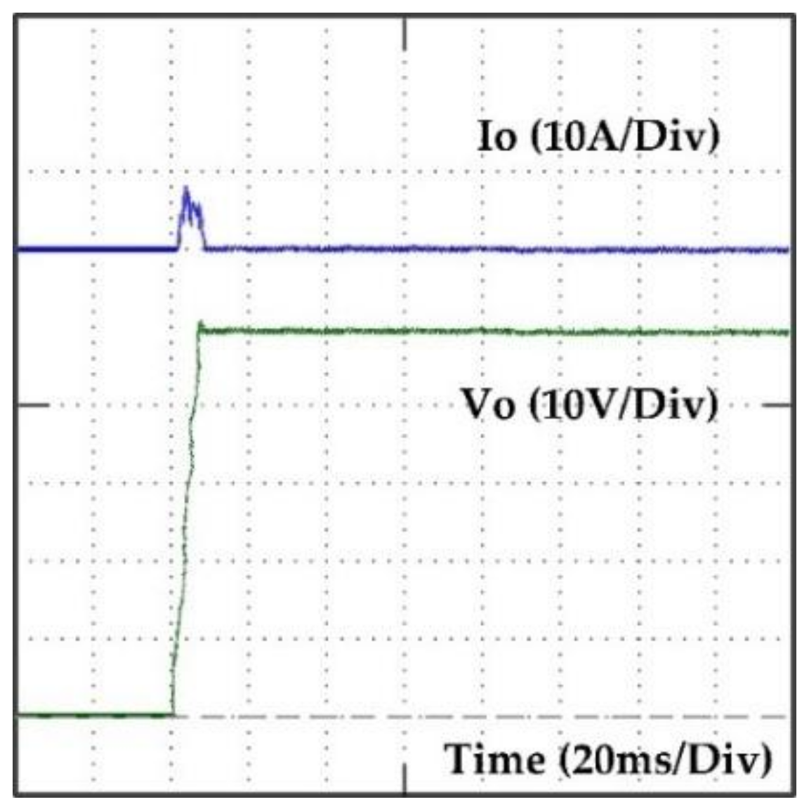
In case four, the proposed five phase soft-start control algorithm was verified in a DAB-IBDC converter under the no load condition. The high-power DAB-IBDC converter (2.5 kW) was connected to neither the supercapacitor bank nor resistive load. The output of the converter not connected to any load was kept freely opened. The soft-start control algorithm was started when the circuit was freshly energized. As no load was connected to the converter, no current flowed into it. Therefore, the proposed five phase soft-start algorithm was concerned on the output capacitor charging voltage and achieved a steady state output voltage without allowing any peak overshoot. At no load, the soft-start algorithm responded in high speed in that the 2.5 kW DAB-IBDC converter achieved a steady state output voltage in 7 ms without any peak over shoot. Figure 17 shows the output voltage and current response as a function of time plot during soft-start period.
6. Conclusions
The proposed five phase digital soft-start algorithm allows the output voltage and current to reach the required value over a precise period, which eradicates the starting inrush current and peak overshoot voltage problems. This prevents the output current and output voltage from an inrush current and peak overshoot voltages by ensuring that the output current does not rise too fast. In addition, the large backflow inrush current released by partially discharging the batteries during the starting period was eliminated. The proposed five phase digital soft-start algorithm alone can prevent the DAB-IBDC converter at standalone renewable energy storage system from an inrush current and peak overshoot voltages without being supported by any additional hardware circuits. A simple super compact size with an elegant design and high reliability were achieved in the DAB-IBDC converter using the proposed five phase digital soft-start and SPS digital control algorithm.
Acknowledgments
This research was supported by Basic Research Laboratory through the National Research Foundations of Korea funded by the Ministry of Science, ICT and Future Planning (NRF-2015R1A4A1041584).
Author Contributions
P. Sathishkumar, Hee-Je Kim conceptualized the idea of this research project. P. Sathishkumar and T. N. V. Krishna designed the DAB-IBDC converter, MOSFET driver, and power units. P. Sathishkumar, Muhammad Adil Khan and Kamran Zeb designed the DSP controller board. P. Sathishkumar, Himanshu developed the magnetic component for the circuits such as the high frequency transformer and inductors. P. Sathishkumar designed the control algorithm and developed the DSP program under the guidance of Hee-Je Kim. P. Sathishkumar, and T. N. V. Krishna made the experimental setup and conducted the experiment. The data were analyzed and organized by Hee-Je Kim and the paper was written by P. Sathishkumar.
Conflicts of Interest
The authors declare no conflict of interest.
References
- Lin, C.E.; Cheng, C.L.; Huang, C.L.; Yeh, J.C. Investigation of magnetizing inrush current in transformers. II. Harmonic analysis. IEEE Trans. Power Deliv. 1993, 8, 255–263. [Google Scholar] [CrossRef]
- Ge, B.; de Almeida, A.T.; Zheng, Q.; Wang, X. An equivalent instantaneous inductance-based technique forbdiscrimination between inrush current and internal faults in power transformers. IEEE Trans. Power Deliv. 2005, 20, 2473–2482. [Google Scholar]
- Shibata, S.; Yamada, H.; Tanaka, T.; Okamoto, M. AC-Chopper-based inrush current suppressor in a wind power generation system with squirrel-cage induction machines. Energies 2018, 11, 397. [Google Scholar] [CrossRef]
- Rico, J.J.; Acha, E.; Madrigal, M. The study of inrush current phenomenon using operational matrices. IEEE Trans. Power Deliv. 2001, 16, 231–237. [Google Scholar] [CrossRef]
- Bukhari, S.S.H.; Atiq, S.; Kwon, B. Elimination of the inrush current phenomenon associated with single phase offline UPS systems. Energies 2016, 9, 96. [Google Scholar] [CrossRef]
- Chetty, P.R.K.; Gallowa, G.; Thollot, P. Soft-Start Circuit for a Power Converter. U.S. Patent No. 4,625,271 A, 25 November 1986. [Google Scholar]
- Shih, F.-Y.; Chen, Y.-T.; Chen, D.Y.; Wu, Y.-P. A Pspice-compatible model of PWM IC for switching power converters with soft-start characteristic. IEEE Power Electron. Drive Syst. 1995. [Google Scholar] [CrossRef]
- Liou, W.-R.; Yeh, M.-L.; Kuo, Y.L. A high efficiency dual-mode buck converter IC for portable applications. IEEE Trans. Power Electron. 2008, 23, 667–677. [Google Scholar] [CrossRef]
- Khan, M.A.; Ko, B.; Alois Nyari, E.; Park, S.E.; Kim, H.-J. Performance Evaluation of Photovoltaic Solar System with Different Cooling Methods and a Bi-Reflector PV System (BRPVS): An Experimental Study and Comparative Analysis. Energies 2017, 10, 826. [Google Scholar] [CrossRef]
- Sathishkumar, P.; Himanshu; Piao, S.; Khan, M.A.; Kim, D.-H.; Kim, M.-S.; Jeong, D.-K.; Lee, C.; Kim, H.-J. A Blended SPS-ESPS Control DAB-IBDC Converter for a Standalone Solar Power System. Energies 2017, 10, 1431. [Google Scholar] [CrossRef]
- Shi, X.; Jiang, J.; Guo, X. An efficiency-optimized isolated bidirectional DC-DC converter with extended power range for energy storage systems in microgrids. Energies 2013, 6, 27–44. [Google Scholar] [CrossRef]
- Xiang, C.; Wang, Y.; Hu, S.; Wang, W. A new topology and control strategy for a hybrid battery-ultracapacitor energy storage system. Energies 2014, 7, 2874–2896. [Google Scholar] [CrossRef]
- Tao, C.; Chen, W.-M. Buck converter with soft switching cells for PV panel applications. Energies 2016, 9, 148. [Google Scholar] [CrossRef]
- Kim, Y.-S.; Hwang, C.-S.; Kim, E.-S.; Cho, C. State of charge based active power sharing method in a standalone microgrid with high penetration level of renewable energy sources. Energies 2016, 9, 480. [Google Scholar] [CrossRef]
- Jeong, D.-K.; Ryu, M.-H.; Kim, H.-G.; Kim, H.-J. Optimized design of bidirectional dual active bridge converter for low voltage battery charger. J. Power Electron. 2014, 14. [Google Scholar] [CrossRef]
- Naayagi, R.T.; Andrew, J.; Shuttleworth, R. High-Power bidirectional DC-DC converter for Aerospace applications. IEEE Trans. Power Electron. 2012, 27, 4366–4397. [Google Scholar] [CrossRef]
- Silva, W.W.A.G.; Donoso-Garcia, P.F.; Seleme, S.I.; Oliveira, T.R.; Santos, C.H.G.; Bolzon, A.S. Study of the application of bidirectional dual active bridge converters in DC nanogrid energy storage systems. In Proceedings of the IEEE Power Electronics Conference (COBEP), Gramado, Brazil, 27–31 October 2013. [Google Scholar] [CrossRef]
- Xiong, F.; Wu, J.; Hao, L.; Liu, Z. Backflow power optimization control for dual active bridge DC-DC converters. Energies 2017, 10, 1403. [Google Scholar] [CrossRef]
- Hua, B.; Chris, M. Eliminate reactive power and increase system efficiency of isolated bidirectional dual-active-bridge DC-DC converters using novel dual-phase-shift control. IEEE Trans. Power Electron. 2008, 23, 2905–2914. [Google Scholar]
- Maruta, H.; Sakai, T.; Shibata, Y.; Kurokawa, F.; Hirose, K. Function switched soft-start method of DC-DC converter for energy management of HVDC system. In Proceedings of the IEEE 2nd international conference on future energy electronics (IFEEC) 2015, Taipei, Taiwan, 1–4 November 2015. [Google Scholar] [CrossRef]
- Zhou, N.; Liu, N.; Zhang, J.; Lei, J. Multi-Objective Optimal Sizing for Battery Storage of PV-Based Microgrid with Demand Response. Energies 2016, 9, 591. [Google Scholar] [CrossRef]
- Clotea, L.R.; Scortaru, P.; Nistor, C.-G. A Novel Start-up Method for Full-Bridge Isolated DC-DC Converter in RES Applications; Transilvania University of Brasov: Brasov, Romania, 2017. [Google Scholar]
- Giuliani, F.; Delmonte, N.; Cova, P.; Costabeber, A.; Castellazzi, A. Soft-Starting Procedure for Dual Active Bridge Converter. In Proceedings of the 2015 IEEE 16th Workshop on Control and Modeling for Power Electronics (COMPEL), Vancouver, BC, Canada, 12–15 July 2015. [Google Scholar] [CrossRef]
- Wen, X.; Zhang, J.; Lu, H. Automatic J-A model parameter tuning algorithm for high accuracy inrush current simulation. Energies 2017, 10, 480. [Google Scholar] [CrossRef]
- Fei, C.; Lee, F.C.; Li, Q. Digital Implementation of Soft Start-Up and Short-Circuit Protection for High-Frequency LLC Converters with Optimal Trajectory Control (OTC). IEEE Trans. Power Electron. 2017, 32, 10. [Google Scholar] [CrossRef]
- Choi, H.-J.; Jung, J.-H. Practical design of dual active bridge converter as isolated bi-directional power interface for solid state transformer applications. J. Electr. Eng. Technol. 2016, 11, 1265–1273. [Google Scholar] [CrossRef]
- Yang, M.; Jin, K.; Ruan, X.; Xu, M. Soft Start Strategy for Bi-directional DC-DC Converter. In Proceedings of the IEEE Power Electronics Specialists Conference (PESC 2007), Orlando, FL, USA, 17–21 June 2007. [Google Scholar] [CrossRef]
- Liu, P.-J.; Hsu, C.-Y.; Chang, Y.-H. Techniques of Dual-Path Error Amplifier and Capacitor Multiplier for On-Chip Compensation and Soft-Start Function. IEEE Trans. Power Electron. 2015, 30, 1403–1410. [Google Scholar] [CrossRef]
- Kurokawa, F.; Sagara, S.; Kurokawa, F.; Shibata, Y.; Kajiwara, K.; Tanaka, T.; Hirose, K. Digital load-dependent soft-start method of DC-DC converter for energy management system. In Proceedings of the International Conference on Renewable Energy Research and Applications (ICRERA), Madrid, Spain, 20–23 October 2013. [Google Scholar] [CrossRef]
- Zhu, L.; Lai, J.-S.; Lee, F.C. Start-Up Circuit and Control for High Power Isolated Boost DC/DC Converters. U.S. Patent No. 6,587,356 B2, 1 July 2003. [Google Scholar]
- Kurokawa, F.; Takano, J.; Takahashi, T.; Bansho, K.; Tanaka, T.; Hirose, K. A novel digital soft-start circuit for dc-dc converter. In Proceedings of the IEEE ICPE, Jeju, Korea, 30 May–3 June 2011; pp. 1761–1766. [Google Scholar] [CrossRef]
- Kurokawa, F.; Sagara, S.; Maruta, H.; Shibata, Y.; Kajiwara, K.; Tanaka, T.; Hirose, K. Digital load-dependent soft-start method of DC-DC converter for energy management system. In Proceedings of the IEEE ICRERA, Madrid, Spain, 20–23 October 2013; pp. 950–954. [Google Scholar] [CrossRef]
Figure 1.
Inrush current without soft-start and with soft-start.

Figure 2.
Soft-start circuit in IC UC2526.

Figure 3.
Traditional resistive soft-start circuits.

Figure 4.
Dual Active Bridge bi-directional DC-DC Converter (DAB-IBDC).

Figure 5.
Circuit current flow diagram and PWM (Pulse Width Modulated) signals plot at phase A soft-start mode.
Figure 5.
Circuit current flow diagram and PWM (Pulse Width Modulated) signals plot at phase A soft-start mode.

Figure 6.
PWM signals plot at phase B soft-start mode.
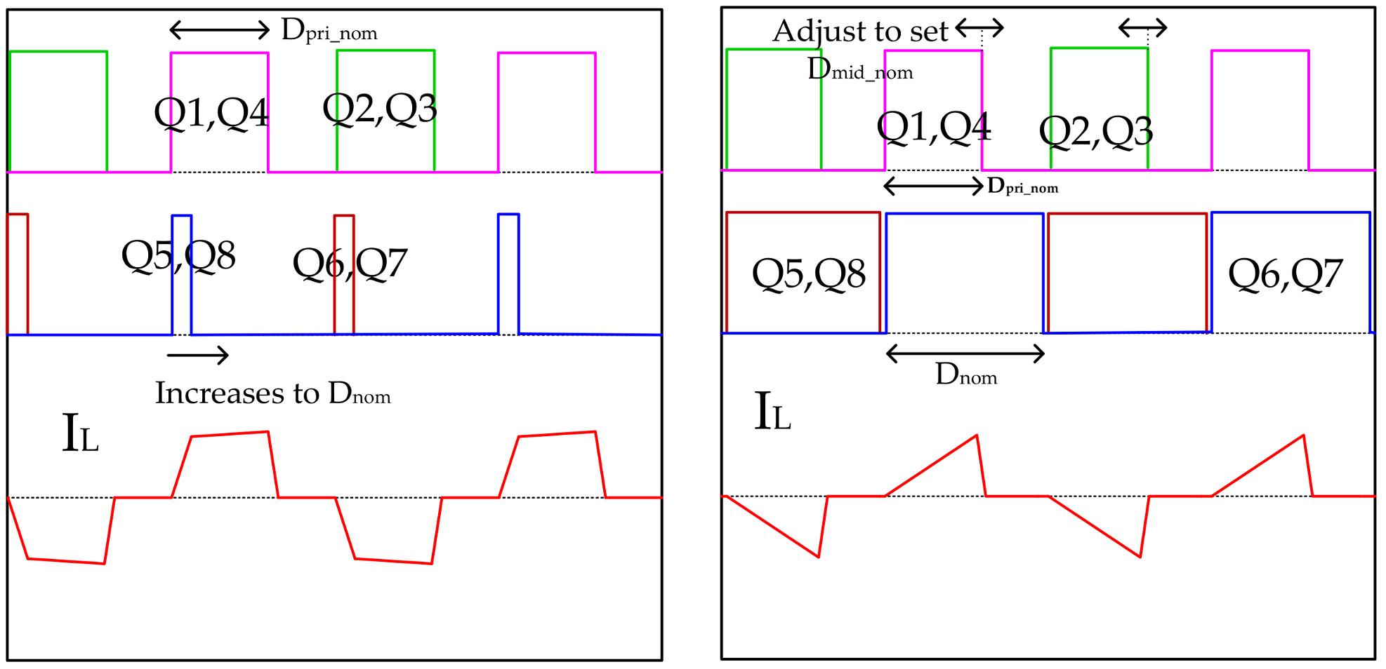
Figure 7.
PWM signals plot at phase C soft-start mode.

Figure 8.
PWM signals plot at phase D soft-start mode.

Figure 9.
PWM signals plot at phase E soft-start mode.
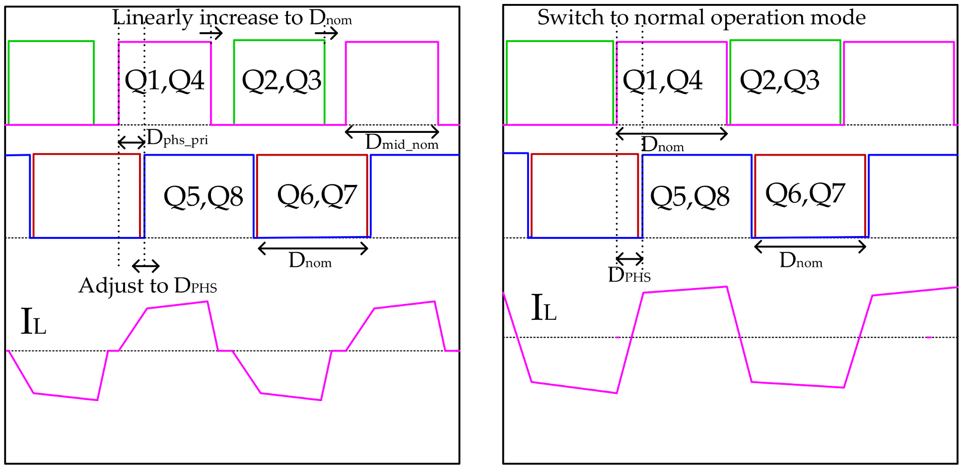
Figure 10.
Digital control board.
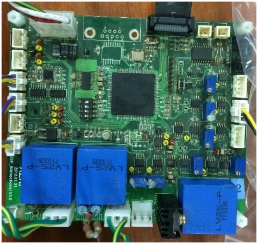
Figure 11.
Five phase soft-start algorithm (a) Flow chart (b) timing diagram.
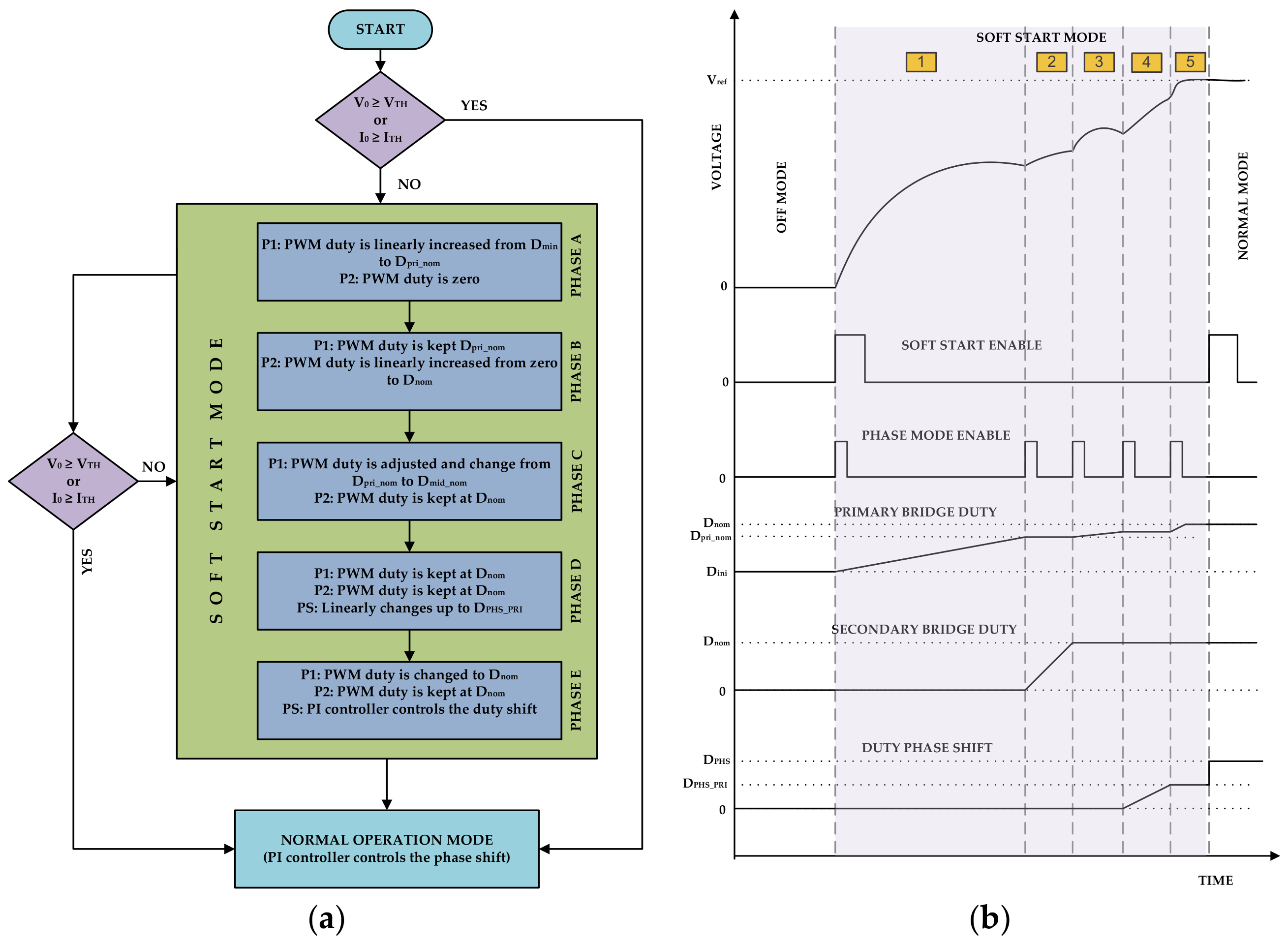
Figure 12.
Digital control loop diagram for DAB-IBDC converter (a) Forward mode charging control loop with MPPT (b) Backward mode dis-charging control loop.
Figure 12.
Digital control loop diagram for DAB-IBDC converter (a) Forward mode charging control loop with MPPT (b) Backward mode dis-charging control loop.

Figure 13.
DAB-IBDC converter with an experimental setup.
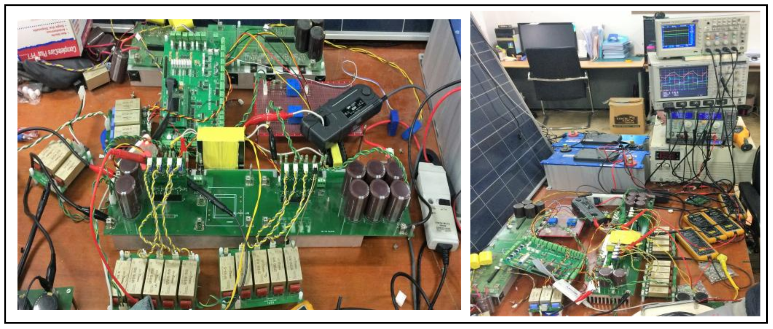
Figure 14.
The supercapacitor bank (153 Wh) with zero initial charging voltage, connected to DAB-IBDC converter. The output voltage and current waveform during the soft-start period (a) 500 W, (b) 1.5 kW and (c) 2.5 kW.
Figure 14.
The supercapacitor bank (153 Wh) with zero initial charging voltage, connected to DAB-IBDC converter. The output voltage and current waveform during the soft-start period (a) 500 W, (b) 1.5 kW and (c) 2.5 kW.

Figure 15.
The supercapacitor bank (153 Wh) with an initial charging voltage 20 V connected to DAB-IBDC converter. The output voltage and current waveform during the soft-start period (a) 500 W, (b) 1.5 kW and (c) 2.5 kW.
Figure 15.
The supercapacitor bank (153 Wh) with an initial charging voltage 20 V connected to DAB-IBDC converter. The output voltage and current waveform during the soft-start period (a) 500 W, (b) 1.5 kW and (c) 2.5 kW.

Figure 16.
The output current and voltage waveform of DAB-IBDC converter during soft-start period while various resistive loads connected to the circuit. (a) 2.5 Ω resistive load at 500 W converter (b) 1.65 Ω resistive load at 1.5 kW converter and (c) 1 Ω resistive load at 2.5 kW converter.
Figure 16.
The output current and voltage waveform of DAB-IBDC converter during soft-start period while various resistive loads connected to the circuit. (a) 2.5 Ω resistive load at 500 W converter (b) 1.65 Ω resistive load at 1.5 kW converter and (c) 1 Ω resistive load at 2.5 kW converter.
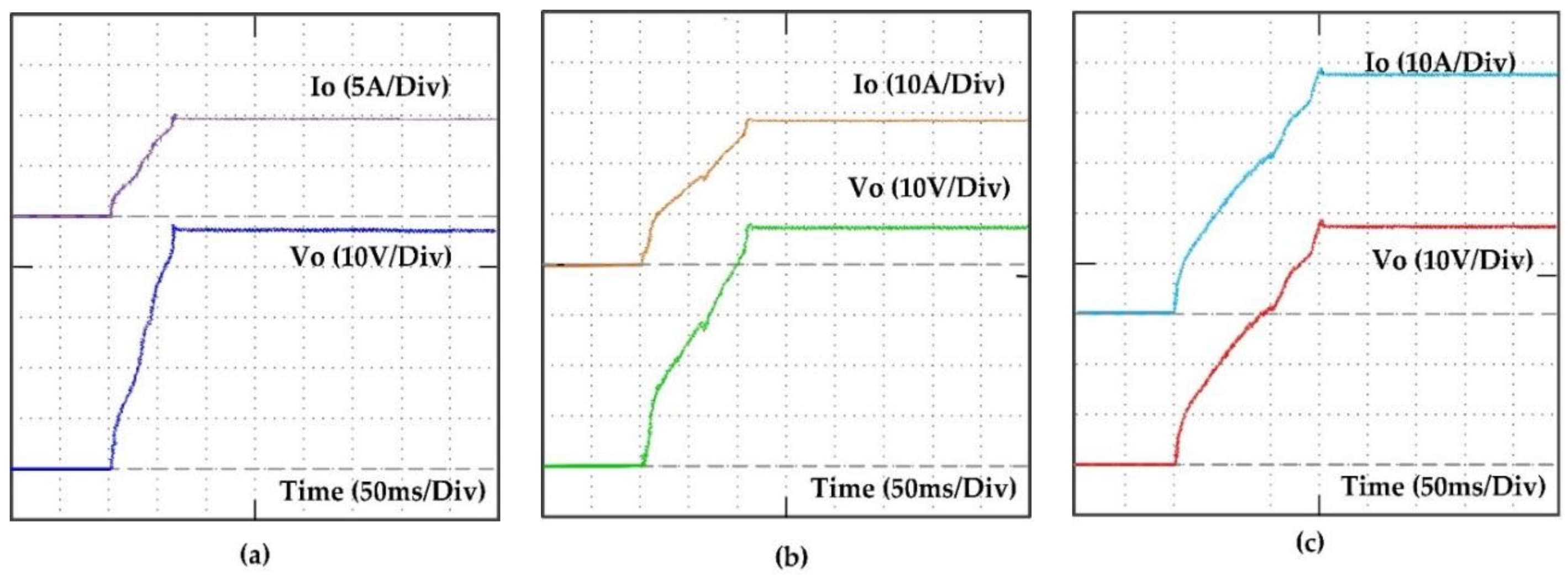
Figure 17.
The output current and voltage waveform of the 2.5 kW DAB-IBDC converter during soft-start period at no load.
Figure 17.
The output current and voltage waveform of the 2.5 kW DAB-IBDC converter during soft-start period at no load.

Table 1.
DAB-IBDC converter design specifications 500 W.
| Parameter | Rating |
|---|---|
| Input Voltage | 290~310 V |
| Power | 500 W |
| Output Voltage | 50 V |
| Transformer turns ratio | 10:2 |
| Switching frequency | 50 kHz |
| Secondary leakage inductance | 2.1 µH |
| Auxiliary inductance | 12.3 µH |
| Input capacitor | 1360 µF |
| Output capacitor | 2040 µF |
Table 2.
DAB-IBDC converter design specifications 1.5 kW.
| Parameter | Rating |
|---|---|
| Input Voltage | 290~310 V |
| Power | 1500 W |
| Output Voltage | 50 V |
| Transformer turns ratio | 10:2 |
| Switching frequency | 50 kHz |
| Secondary leakage inductance | 2.1 µH |
| Auxiliary inductance | 2.8 µH |
| Input capacitor | 1360 µF |
| Output capacitor | 2040 µF |
Table 3.
DAB-IBDC converter design specifications 2.5 kW.
| Parameter | Rating |
|---|---|
| Input Voltage | 290~310 V |
| Power | 1500 W |
| Output Voltage | 50 V |
| Transformer turns ratio | 10:2 |
| Switching frequency | 50 kHz |
| Secondary leakage inductance | 2.1 µH |
| Auxiliary inductance | 2.8 µH |
| Input capacitor | 1360 µF |
| Output capacitor | 2040 µF |
© 2018 by the authors. Licensee MDPI, Basel, Switzerland. This article is an open access article distributed under the terms and conditions of the Creative Commons Attribution (CC BY) license (http://creativecommons.org/licenses/by/4.0/).
Share and Cite
MDPI and ACS Style
Sathishkumar, P.; Krishna, T.N.V.; Himanshu; Khan, M.A.; Zeb, K.; Kim, H.-J. Digital Soft Start Implementation for Minimizing Start Up Transients in High Power DAB-IBDC Converter. Energies 2018, 11, 956. https://doi.org/10.3390/en11040956
AMA Style
Sathishkumar P, Krishna TNV, Himanshu, Khan MA, Zeb K, Kim H-J. Digital Soft Start Implementation for Minimizing Start Up Transients in High Power DAB-IBDC Converter. Energies. 2018; 11(4):956. https://doi.org/10.3390/en11040956
Chicago/Turabian StyleSathishkumar, P., T. N. V. Krishna, Himanshu, Muhammad Adil Khan, Kamran Zeb, and Hee-Je Kim. 2018. "Digital Soft Start Implementation for Minimizing Start Up Transients in High Power DAB-IBDC Converter" Energies 11, no. 4: 956. https://doi.org/10.3390/en11040956
Note that from the first issue of 2016, this journal uses article numbers instead of page numbers. See further details here.