High-Efficiency Small-Scale Combined Heat and Power Organic Binary Rankine Cycles


1
Department of Mechanical and Industrial Engineering, University of Brescia, Via Branze 38, 25123 Brescia, Italy
2
Department of Mechanical Engineering, International Islamic University, 44000 Islamabad, Pakistan
*
Author to whom correspondence should be addressed.
†
These authors contributed equally to this work.
Energies 2018, 11(4), 994; https://doi.org/10.3390/en11040994
Submission received: 31 March 2018
/
Revised: 15 April 2018
/
Accepted: 17 April 2018
/
Published: 19 April 2018
Abstract
:Small-CHP (Combined Heat and Power) systems are generally considered a valuable technological option to the conventional boilers, in a technology developed context. If small-CHP systems are associated with the use of renewable energies (biomass, for example) they could play an important role in distributed generation even in developing countries or, in any case, where there are no extensive electricity networks. Traditionally the considered heat engines for micro- or mini-CHP are: the gas engine, the gas turbine (with internal combustion), the steam engine, engine working according to the Stirling and to the Rankine cycles, the last with organic fluids. In principle, also fuel cells could be used. In this paper, we focus on small size Rankine cycles (10–15 ) with organic working fluids. The assumed heat source is hot combustion gases at high temperature (900–950 ) and we assume to use only single stages axial turbines. The need to work at high temperatures, limits the choice of the right organic working fluids. The calculation results show the limitation in the performances of simple cycles and suggest the opportunity to resort to complex (binary) cycle configurations to achieve high net conversion efficiencies (15–16%).
1. Introduction
A sharp rise in global energy demand and ambitions to curtain global greenhouse gas emissions have led to various innovative alternatives in energy sector. Utilisation of low quality heat source, for example, is one of the key ingredient of the solution to improve efficiencies of current energy conversion and electricity generation processes. Among these ideas and technologies, the Organic Rankine Cycle (ORC) has gained much attention over almost a century. Unlike the conventional Steam Rankine Cycle, ORC uses unconventional fluids, low boiling and stable hydrocarbons mostly, to extract work from the medium to low grade sources with a broad power sizes interval.
Rankine cycles with organic fluids can also be used, in principle, to convert high temperature heat from any source in useful work, but applications in this context comes up against the thermochemical stability of the working fluid and the very high volumetric expansion ratios of the thermodynamic cycles, which involve many turbine stages, technologic difficulties and high costs, in particular for small-size engines. On the other hand, the low electric efficiency of the small-scale power generation systems, justifies and makes convenient to recover heat from the engine, to realise the so called CHP (Combined Heat and Power) systems. Nevertheless, choosing appropriate working fluid for the operation of ORC is essential for its thermo-economic viability, [1,2,3].
CHP-based generation systems have ramped up over the last decade especially in Europe. For instance, in UK only the share of CHP-based systems is around by 2015, and about 10% of CHP systems used renewable fuel sources, [4]. However, the size of CHP plants and their connectivity to non-connected zones or off-grid areas is an issue.
With increasing global pressure for the reduction of the carbon footprint, mechanical utilisation of natural resources such as biomass, for small CHP engines, in an efficient and environment friendly manner is highly recommended. Indeed, for lesser grade biomass and derived fuels, several plants using organic fluids are already operational for low to medium power rating range (1–10 ). Unfortunately, small scale ORC supplied by the external combustion of wood are affected by intrinsic rather low electrical efficiencies.
As it is well known among the main operational modes to convert solid and dry biomass in electrical energy there are the direct combustion and the gasification, [5]. Usually, the syn-gas from small scale gasifiers is utilised as fuel in internal combustion engines (ICE) or micro-gas turbines, [5,6,7].
With regard to the ICE, small CHP engines (nearly ) fuelled with natural gas, have electrical efficiencies approximately of 25%, [8]. Micro-gas turbines have turbo-machines rotating at very high speeds (50,000–250,000 rpm), with efficiencies of about 25% (in the power range about ten ), decreasing to 10% when the power is some , [9]. External combustion micro-gas turbines, working with lower maximum temperatures, have also lower electric efficiencies. Potentially, the syn-gas can be used in fuel cells, also, [10].
Among the external combustion engines, Stirling engines, [11,12,13], and the small steam engines and steam turbines must also be mentioned.
Nevertheless, in this paper, we concentrate only on small size ORC (Organic Rankine Cycle) engines, without to have pretensions to compare each other all the available and usable different heat engines. The aim is, considering the limits of design and utilisation of single stage axial turbines, to discuss and to identify some technically possible configurations of the thermodynamic cycles. Exploring so the potential of small ORC engines at high temperatures.
As the specific application here considered is the heat recovery from a high temperature source, one has to expect very large volumetric expansion ratios (of the order of many tens). As a consequence, the natural expander to choose is a turbine. Volumetric expander combined with organic Rankine cycles are considered in literature, and, in accordance with their peculiar characteristics, the expansion ratios are limited to 2–10, [14,15]. Furthermore, (for some ) the isentropic efficiency of the commercially available volumetric expanders, basically, decreases to fifty per cent for pressure ratios greater than about 10, [15].
As the engines working according to the Rankine cycles convert external heat into mechanical work, we assumed, as a reference example, the availability of a mass flow rate of syn-gas of about (as available from some marketable small gasifiers), with a lower heating value of about (a value roughly equal to the lower heating values of wood chips with high moisture content −40 to 60%). The combustion of the syn-gas produces gases at high temperatures (900–950 ), making it particularly difficult to achieve a full exploitation of the heat source by a simple organic Rankine cycle. These severe conditions, associated with the small size power, worsen the design problems, and to carry that thermodynamic engines out proves to be really demanding.
The topic is not entirely new. For example, in [16,17] some small engines from to (with solar, geothermal or exhaust gases as heat sources) are cited and described. In [18] the design of a small solar engine of using scroll expanders is discussed. A supersonic turbine (at a design rotational speed of 100,000 rpm, with a measured efficiency of about fifty per cent) for a unit of is presented in [19]. In [20] a modular, hermetically sealed turbine-generator unit is discussed. The working fluid, a refrigerant, has an inlet design temperature of 200–220 and the expansion ratio is about 10–30. The turbine rotor and the high-speed generator are hermetically sealed and the shafts are magnetically levitated. The design turbine rotational speed is 20,000 rpm.
A biomass Rankine engine is described in [21]. The considered working fluid is toluene, with turbine, electrical generator and pump running at 25,000 rpm.
Usually, the selected working fluids are common refrigerants, the maximum temperatures are rather low (though the maximum temperature of the gaseous heat source is high) or, on the contrary, the considered Rankine cycles have a substantial superheating, often with volumetric expanders, [24]. In this work we assume as calculation hypotheses the use of only one stage (axial) turbine, to minimise the mechanical complexity of the expander, and to resort only to saturated thermodynamic cycles that, fixed the maximum operative temperature, have potentially the better thermodynamic efficiency. The superheating could be useful but, it adds a further design variable and increases the thermal power of the recuperator. For simplicity it was here neglected.
These assumptions, together with the small power levels and the high temperature of the heat source, to a large degree influence the working fluids selection and the choice of the evaporation and condensation temperatures. Given the specific application, not many are the working fluids available on the market and the choice is reduced. A discussion of the properties of some available organic working fluid for high temperature applications is in Section 2.
A great current disadvantage of small power Rankine cycles is the considerable specific cost of the engine in comparison with the reciprocating internal combustion engines and, basically, in the small power sizes range, the lower efficiencies. Nevertheless, economic considerations (discussed, for example, in references [18,22,23]) are not here considered. In the following analysis, the efficiency of a hypothetical gasifier (or wood combustor) is not taken into account because we focused on the ORC engine.
2. The Working Fluids
In our case, the selection of the right working fluid was primarily conditioned by the low level of the useful mechanical power. In the cases here discussed the turbine power will result in about 10–15 ; so, strictly from the thermodynamic point of view, the ideal working fluid should have (i) a large molecular mass, (ii) an high critical temperature and an high boiling point and (iii) a low molecular complexity, [25,26,27,28], and ([29], Chapter 3, p. 125). In addition, the fluid has to be thermally stable at the operating temperatures and, if possible, non corrosive and with a good environmental acceptability.
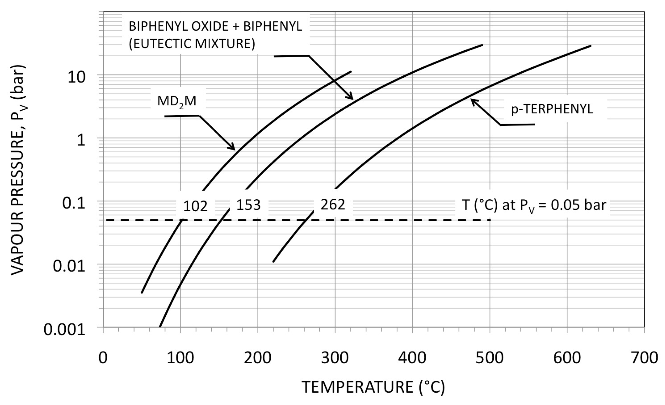
Unfortunately, frequently, high boiler temperatures and high molecular mass involve a great number of atoms and, as a consequence, a great molecular complexity and the need of recuperators after the expansion in turbine. The molecular complexity of a working fluid is a function of the number of atoms in the molecule. As the molar specific heat at constant pressure of the vapour augments essentially with the number of atoms in the molecule, when this latter increases the vapour slope in the Temperature-Entropy thermodynamic plane increases too. Fixed at such a temperature, when the (positive) local contribution of the heat capacity to the slope, exceeds the (negative) contribution of the vapour pressure, the saturation dome inclines to the right. In this cases, the expansion ends in the superheating phase. In addition, fixed a pressure expansion ratio, the temperature drop during the expansion decreases and a recuperator after the expansion results really necessary. In Table 1 there are some properties of working fluids considered in this work. In Figure 1 are reported the vapour pressures of the considered fluids; in Figure 2 there are the dew and the bubble lines in the Temperature-Entropy plane. The three considered working fluids are all suitable for high temperature applications.
Decamethyl-tetra-siloxane () is a member of the siloxane family. Poly-dimethyl-siloxanes are largely used and are characterised by a relatively high thermal stability (used up to 250–300 ). They are physiological inert and they have good lubricating properties. Siloxanes are used as working fluids in commercial biomass Rankine cycles, [30]. In [31] the design of a small radial turbine (of about ) with a siloxane is discussed. The evaluated turbine efficiency is said to be about 0.76, at a rotational speed of 31,000
The eutectic mixture of diphenyl (, 26.5% in mass) and diphenyl oxide (, 73.5% in mass), is a well-known synthetic heat transfer fluid. The mixture, according to the manufacturers, is utilizable up to , [32] The p-terphenyl, the most common isomer among the terphenyls, has an high critical temperature (about ) and it is probably as thermally stable as the eutectic mixture of diphenyl and diphenyl oxide. Terphenyls, for their high boiling point and thermal stability, were considered and thoroughly studied as cooling and moderating fluids in some particular nuclear reactors, ([33], Chapter 17, p. 411). Among the organic fluids, the eutectic mixture of biphenyl oxide and biphenyl and the p-terphenyl are considered the most thermally stable. The eutectic mixture is proposed as heat transfer fluid up to .
3. The Cycle Performances
The assumed parameters for the calculations are in Table 2. The product , or the product between the mechanical efficiency and the generator efficiency , is assumed unitary in the following calculations. An exception are the results in Table 3 and Table 4, where the product was assumed equal to 0.9.
To assign an exact value to the product is not really simple. Usually, the friction power loss is proportional to the rotational speed and, for an alternator, in addition to electrical losses, the windage power loss increases with the cube of the rotational speed. Furthermore, the magnetic losses are also connected with the rotational speed. In reference [34], for example, for the design of a turbo-alternator of , the assumed alternator and mechanical efficiencies were about eighty per cent and ninety seven per cent respectively. Where necessary and just as a reference, here, optimistically, we assumed for their product a value of ninety per cent.
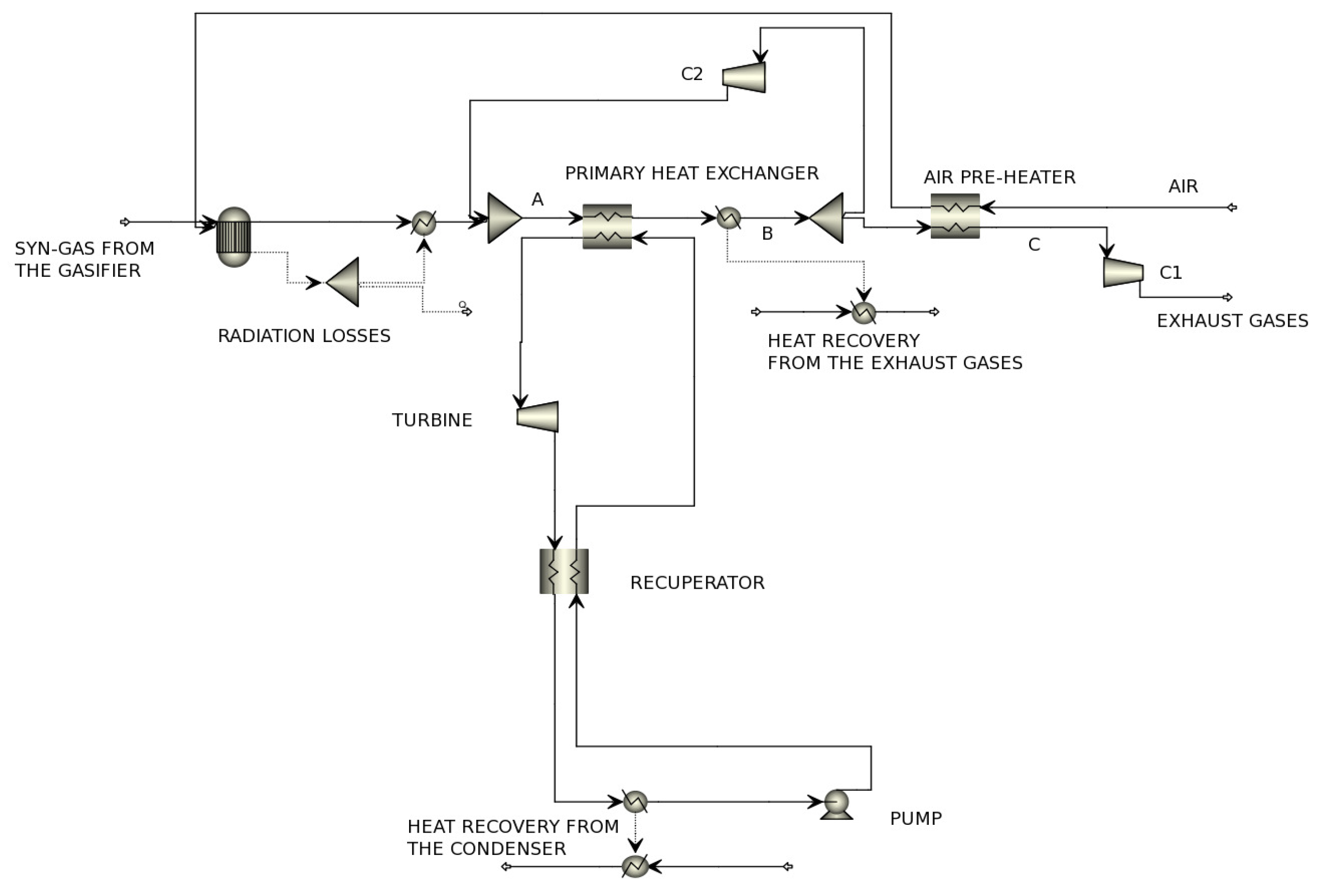
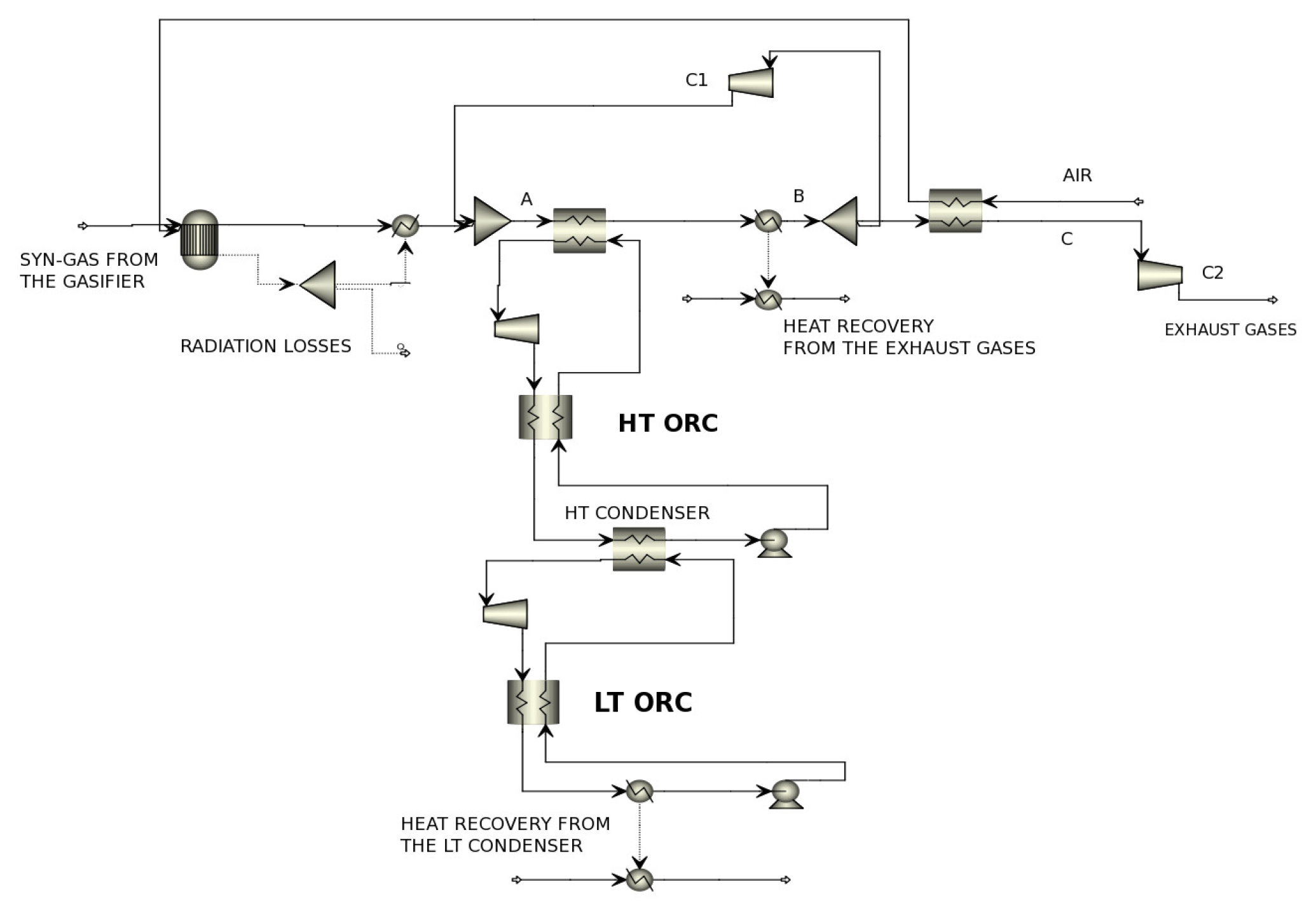
In Figure 3 there is the considered plant scheme for the syn-gas boiler whit a recovery Organic Rankine cycle. For the boiler section, for simplicity and just as a reference, we assumed a simplifying configuration of the biomass boiler described in [35]. The combustion chamber was simulated (using AspenPlus V7.3®, by a Gibbs Reactor, with a radiation loss equals to one per cent of the thermal chemical reaction power. A circulation of an appropriate mass flow rate of gases assures a temperature in the stream A of . A direct primary heat exchanger provides the heat recovery from the hot combustion gases to the working fluid of the Rankine cycle. The temperature in the stream B was assumed equal to and an air pre-heater cools the gases to , the temperature in stream C, before their discharge in the atmosphere. The fans and provide the circulation and the discharge of the exhausted gases, respectively. Radiation losses in the chimney stack were neglected. After the primary heat exchanger, before the point B, we supposed a possible heat recovery with water (heated from to ); a second heat recovery is on the condenser of the ORC.
For the analysis of the performances of the different single Rankine cycle we supposed the following design constraints:
- a single stage axial turbine, to minimise the mechanical complexity of the expander;
- only saturated cycles. Firstly for simplicity, avoiding so a further design variable, and then to avoid to increase the thermal power of the recuperator. In addition, saturated cycles have, fixed the maximum and minimum temperatures, the better thermodynamic efficiency.
In the following, firstly, we will discuss the results with regard to the scheme configuration in Figure 3.
Case (a)—single heat recovery cycle
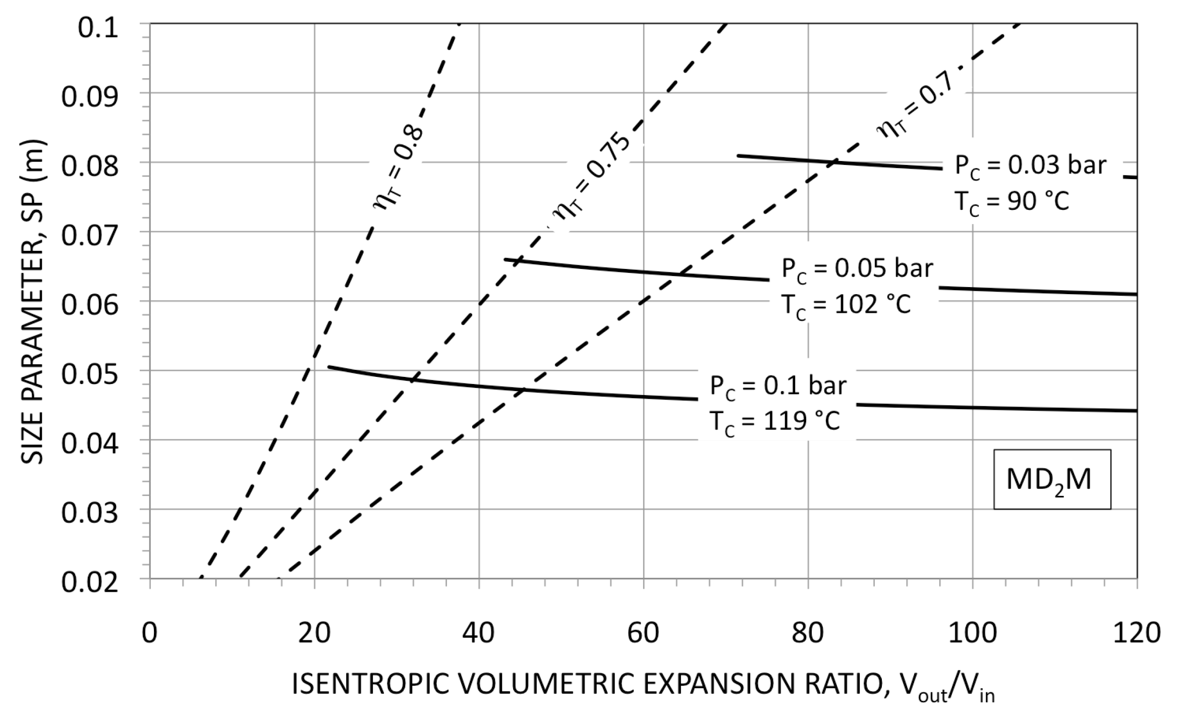
As the turbine efficiency depends on the size parameter and on the isentropic volumetric expansion ratio , [36], Figure 4 gives the parameter and the ratio for cycles with as working fluid. In Figure 4 the condensation pressure was assumed equal to , and . The ratio , fixed a condensation pressure , results a function of the evaporation pressure and increases with it.
In the case of a condensation pressure equal to , for example, (see Figure 4) it seems very difficult to design an efficient single-stage turbine; if , the size parameter almost halves, but, as also the isentropic volumetric expansion ratio decreases substantially, it is possible to realise single stage turbines with a very good efficiency (≈80%). At least for isentropic expansion ratios between 20 and 30.
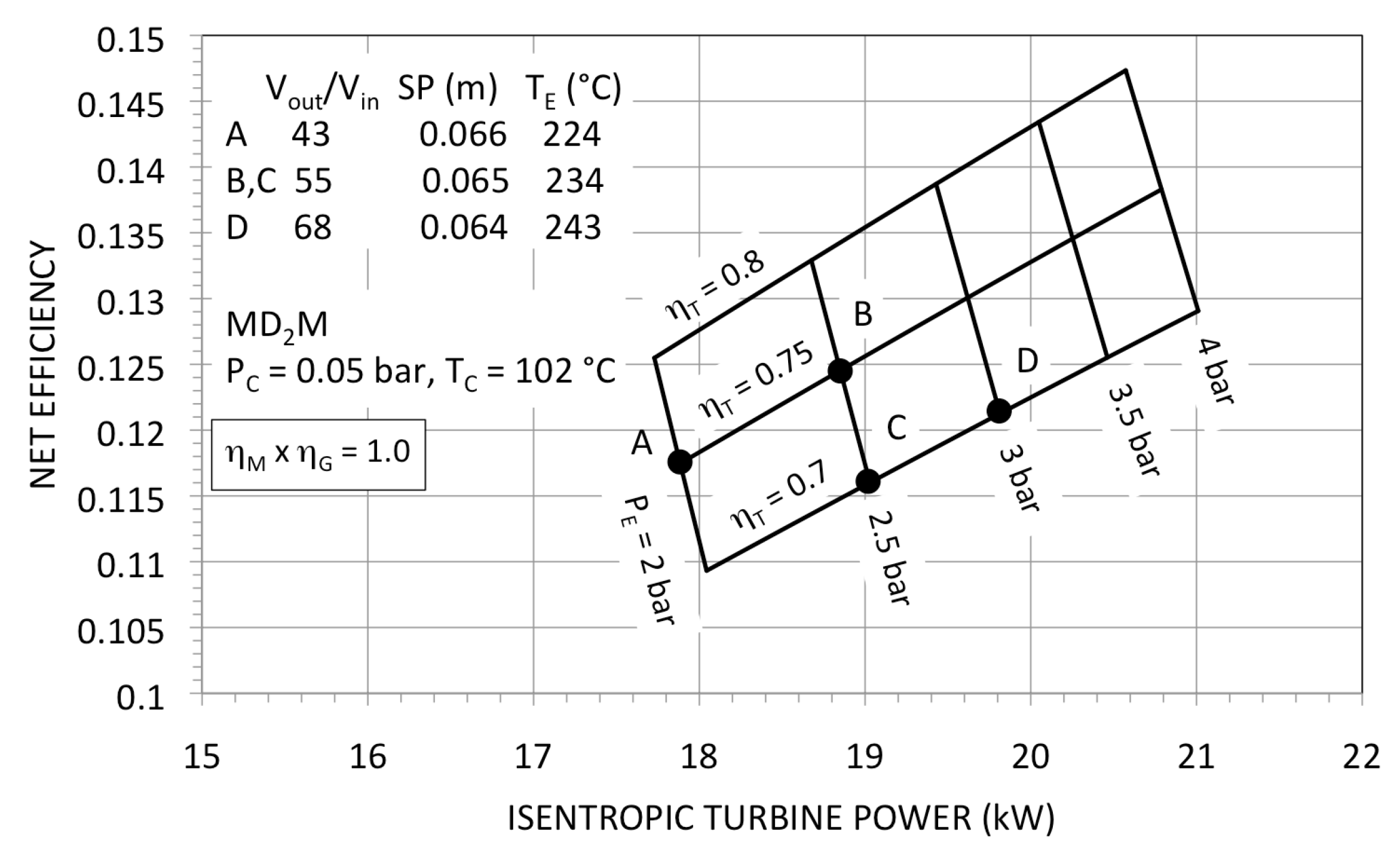
Assuming, as a reference, a condensation pressure of , in Figure 5 are the net cycle efficiency and the isentropic turbine power for different evaporation pressures and for three values of turbine efficiency (0.7, 0.75 and 0.8).
Points , , and represent different cycle configurations. For example, fixing (evaporation temperature ), cycles and have the same isentropic expansion ratio ( 55) and the same size parameter ( 0.065). Then, in principle, according to Figure 4, the turbine efficiency could take an intermediate value between 0.7 and 0.75. If 0.7 (cycle ) the cycle efficiency results about 0.116; if 0.75 (cycle ) the cycle efficiency increases to about 0.125.
As the condensation is at about () it is possible to recover heat from the condenser of the thermodynamic cycle and, consistently with the plant scheme assumed (see Figure 3), it is possible to recover heat also from the pre-cooling of the exhaust gases. Considering the recovered thermal power as a further useful effects, the a “First Law” efficiency (the CHP efficiency) for cycle , for example, increases to about 0.9.
As you can derive from Figure 5, the evaporation temperature , in the allowable cases A, B, C and D, is rather low in comparison with the maximum temperature of the available hot gases (), so it is worth considering binary cycles too: a topping cycle at 350–400 and a bottoming cycle at 200–250 . As a matter of fact (with the considered constraints), it is impossible, using a single fluid, to realise the full expansion in a one stage turbine.
Case (b)—binary heat recovery cycle
Assuming as a basic constrain a one stage axial turbine, the need to limit the volumetric expansion ratio has as a result (fixed a condensation pressure of ) an evaporation temperature rather low: see Figure 4 and Figure 5.
As the heat source is, according to the assumed model of the boiler, at a temperature of , a possible option to attempt a better exploitation of its thermodynamic potential could be to resort to a binary system, see the scheme in Figure 6. The condenser of the “High Temperature” module provides the heat for the evaporation of the “Low Temperature” thermodynamic cycle.
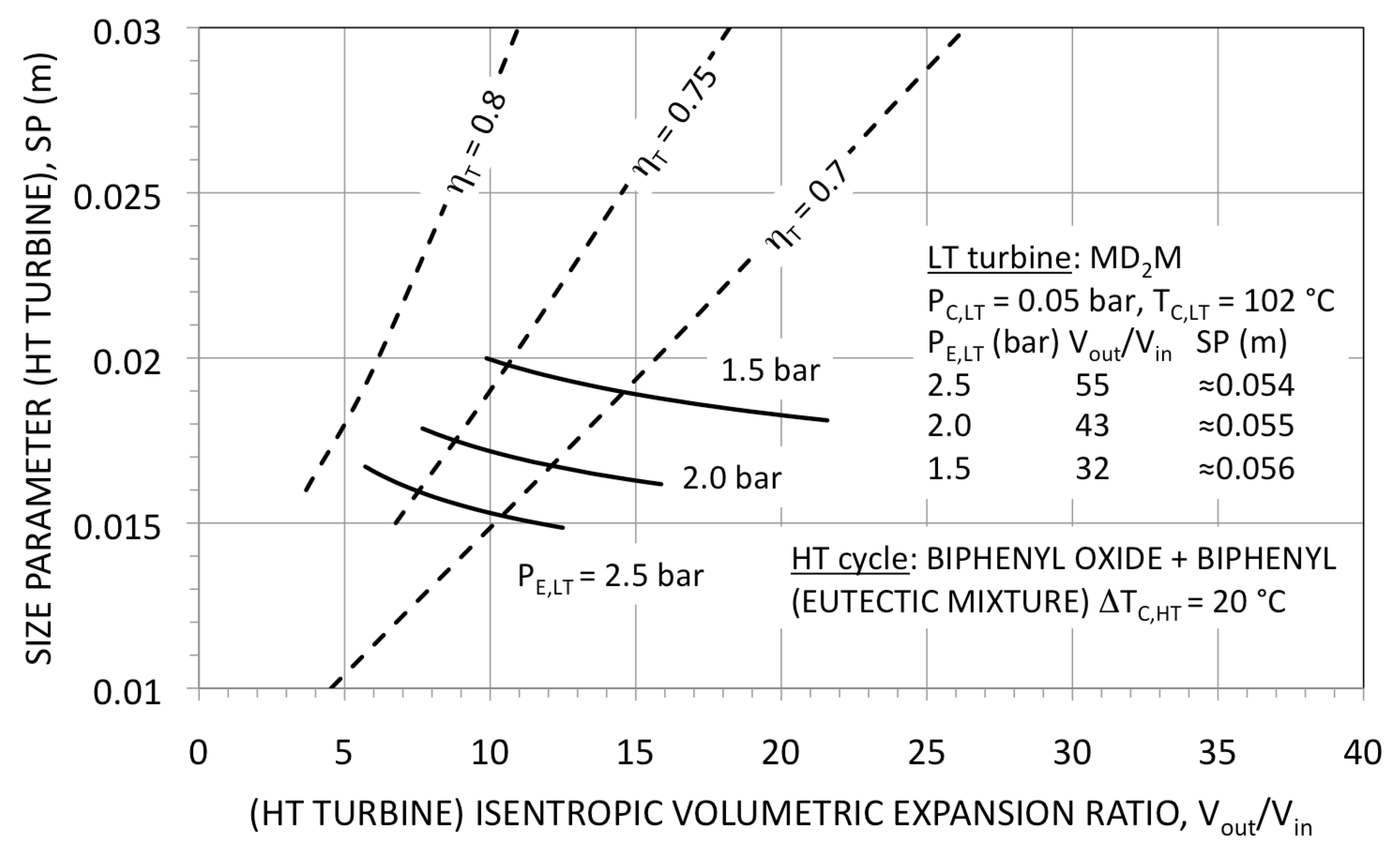
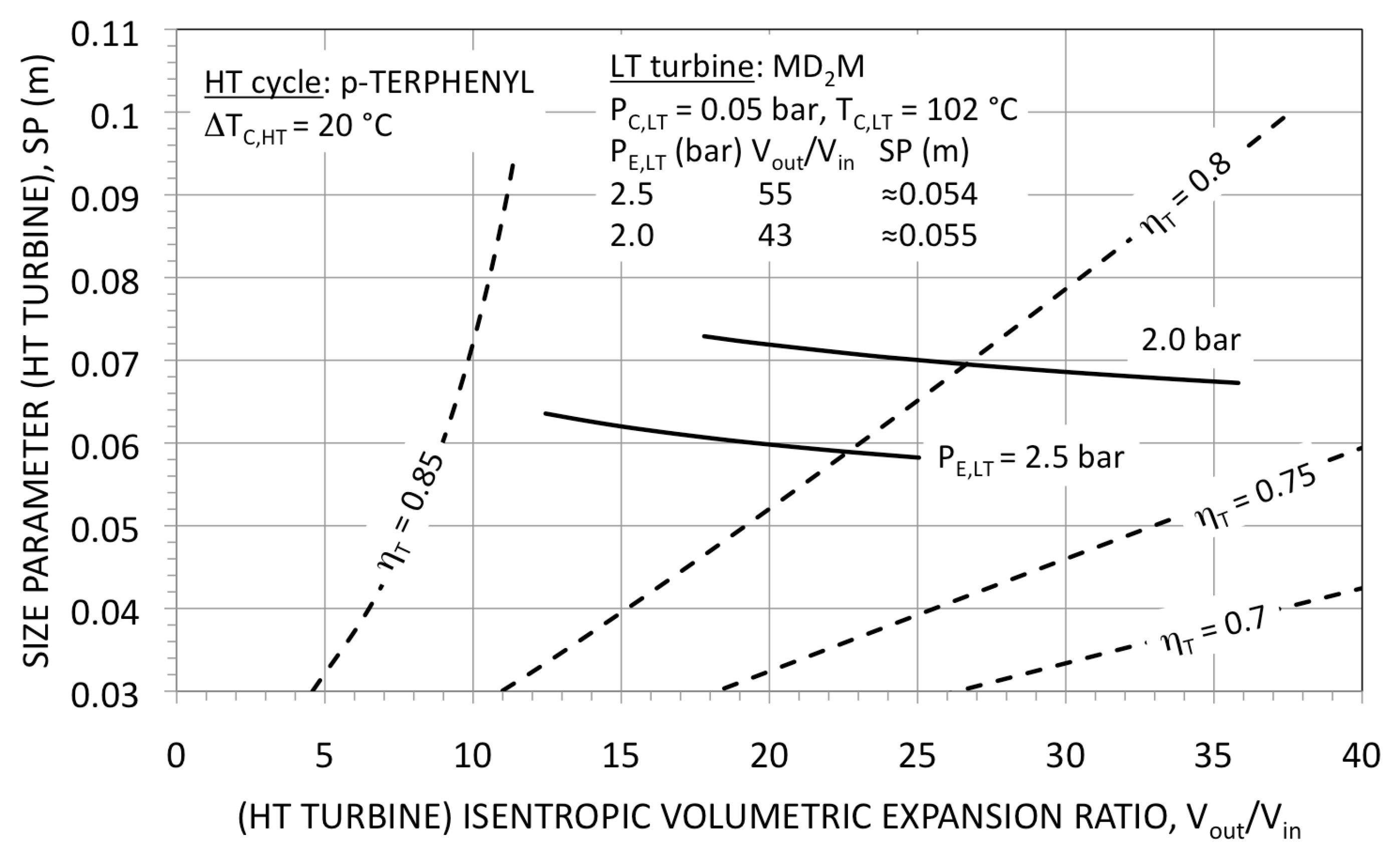
Assuming as working fluid in the “Low Temperature” module, Figure 7 and Figure 8 give the size parameter and the isentropic volumetric expansion ratio for the HT turbine. In Figure 7 and Figure 8 an eutectic mixture of biphenyl oxide and biphenyl and pure p-terphenyl as working fluids in the HT cycle are considered, respectively.
Against ratios of the same magnitude, the turbine with p-terphenyl has size parameters four times greater than the corresponding values for the eutectic mixtures, allowing so the design of better turbines.
The results of net cycle efficiency and of isentropic power for binary cycles with the eutectic mixture and with p-terphenyl as working fluids in the HT cycles are in Figure 9 and Figure 10, respectively. Resorting to binary systems, the net efficiency increases from about 12–13% to about 18–19% (whit ). In all considered cases the CHP efficiencies result about 90%.
In Table 3 there are some results for the cycle corresponding to the point in Figure 5. Assuming , the cycle efficiency results 12.5%, while the net efficiency is 11%. The recovered thermal power, supposed to be available in hot water at , is about 6 times the electrical turbine power.
In Table 4 there are the results for two binary configurations. In the first case, the working fluid for the HT section is terphenyl (case C of Figure 10), in the second one the working fluid is the eutectic mixture of biphenyl oxide and biphenyl (case D of Figure 9). The gain in electric efficiency is of 0.051 points in the first case and 0.041 in the second case with respect to the single cycle, respectively. The electrical power, in the case of the binary cycles, increases of about .
Although with the assumed calculation hypotheses, the global performances of the two considered binary cycles are quite similar, the turbines of the two HT modules results are very different. For its limited Size Parameter (see Figure 7) the turbine with the eutectic mixture requires a partial admission and a very small admission degree (see Table 5). Then its efficiency result could be considerably lower than the values here assumed.
4. Conclusions
From the analysis and from the results presented and discussed in the previous sections, it follows that the design of truly efficient small high temperature Rankine engines is really very difficult, as one has to reconcile high efficiencies with low cost and demanding technological constraints.
In conclusion:
- Rankine cycles at high temperatures and small useful power require in general very high volumetric expansion ratios that, combined with small Sizes Parameters, usually demands: (i) axial multi-stages turbines with (ii) a high rotating speed, that is, very expensive turbomachines with rather low internal efficiencies. Assuming one-stage turbines the worked out expansion ratios are limited and the resulting thermodynamic cycle efficiencies are modest. A possible way to solve the problem is to resort to “standard” HT and LT Rankine modules and to combine them properly, achieving binary cycles.
- A significant contribution to the final cost of the engine is certainly due to the heat exchangers. The surface of all the necessary heat exchangers can be considered proportional to the sum : the sum of the total heat transfer coefficients times the heat transfer area, in which the index i represents the i-th heat exchanger. For the single cycle in Table 3, results , while for the binary cycle with terphenyl (in Table 4), is : 55% more, but against an efficiency and an electrical power 46% and 39% higher, respectively. In the case of the binary (LT)/Terphenyl (HT) cycle, the of the HT condenser represents the 35 per cent of the and it could results so a demanding component to design.
Here we investigated the potential gains in efficiency and power resorting to binary modules each one with single axial turbines, in comparison with simple cycles, for high temperature and small size power Rankine cycles. An in-depth economic analysis - being very difficult without detailed calculations and design and off-design evaluation - is outside the aims of this work. However, the complexity and (probably) an higher maintenance needs for the binary systems must be cited and should be taken in account.
In principle, the design of axial turbines could be easily adapted to any expansion ratio and to any power size. The machine does not require lubrication (and this is an advantage: the oil mixed with the working fluid can produce thermal degradation at high temperature) and even single stages, as discussed in the previous Sections, for the power sizes here considered, can have good efficiencies. Therefore, in the opinion of the authors, small dynamic expanders are generally preferable to volumetric expanders.
The considered reference syn-gas flow rate, from a small commercial gasifier, was selected with the intent of exploring the lower power limits. Increasing the available thermal power, the “scale effects” offer advantage to costs and to efficiencies. The coupling of ORC modules and small biomass stoves could be, strictly from the thermodynamic point of view, certainly less problematic, but the efficiencies will result lower.
Lastly, the problem of the choice of the right working fluids should be mentioned. Steam for small power sizes cannot be used. However, if one wants to make the most of the high temperature sources, the thermal stability limits the choice of the available organic fluids.
In the case of external combustion of syn-gas, the obtainable CHP efficiencies (of about 80–90%) are in agreement with those of the conventional ICE of similar mechanical power. However the electrical efficiencies result lower (about 10–15% against 15–25%).
On the credit side, the small Rankine engines with organic fluids can convert heat from any source and the development of small HT and LT modules could be interesting in many different applications. From this point of view, the choice of single-stage turbines could favour the design of small ORC modules as simple as possible, efficient and best used in well-defined temperature ranges. Small modules are potentially combinable with each other or used separately, according to the requirements.
Author Contributions
The authors contributed equally to this paper.
Conflicts of Interest
The authors declare no conflict of interest.
Abbreviations
The following abbreviations, symbols and subscripts are used in this manuscript:
| molar heat capacity at constant pressure, | |
| P | pressure, |
| condensation pressure, | |
| evaporation pressure, | |
| R | gas constant, |
| S | entropy, |
| T | temperature, or |
| minimum temperature difference in the “Primary Heat Exchanger”, | |
| minimum temperature difference in the condenser, | |
| total heat transfer coefficient times heat transfer area, | |
| cycle efficiency | |
| pump efficiency | |
| isentropic turbine efficiency | |
| mechanical and electrical efficiency (pump and turbine) | |
| isentropic volume flow at turbine inlet | |
| isentropic volume flow at turbine outlet | |
| specific speed () | |
| specific diameter () | |
| High Temperature cycle | |
| Low Temperature cycle | |
| Organic Rankine Cycle | |
| inlet | |
| outlet | |
| property in critical conditions |
References
- Lakew, A.A.; Bolland, O. Working fluids for low-temperature heat source. Appl. Therm. Eng. 2010, 30, 1262–1268. [Google Scholar] [CrossRef]
- Ngoc Anh, L.; Wendland, M.; Fischer, J. Working fluids for high-temperature organic Rankine cycles. Energy 2011, 36, 199–211. [Google Scholar]
- Scaccabarozzi, R.; Tavano, M.; Invernizzi, C.M.; Martelli, E. Thermodynamic Optimization of heat recovery ORCs for heavy duty Internal Combustion Engine: Pure fluids vs. zeotropic mixtures. Energy Procedia 2017, 129, 168–175. [Google Scholar] [CrossRef]
- Anonymous. Digest of UK Energy Statistics; Statistical Report; Department of Energy and Climate Change: London, UK, 2016.
- Carrara, S. Small-Scale Biomass Power Generation. Ph.D. Thesis, University of Bergamo, Bergamo, Italy, 2010. [Google Scholar]
- Bocci, E.; Sisinni, M.; Moneti, M.; Vecchione, L.; Di Carlo, A.; Villarini, M. State of art of small scale biomass gasification power systems: A review of the different typologies. Energy Procedia 2014, 45, 247–256. [Google Scholar] [CrossRef]
- Gonzales, A.; Riba, J.-R.; Puig, R.; Navarro, P. Review of micro- and small-scale technologies to produce electricity and heat from Mediterranean forests’ wood chips. Renew. Sustain. Energy Rev. 2015, 43, 143–155. [Google Scholar] [CrossRef]
- Capaldi, P. A high efficiency 10kWe microgenerator based on an Atkinson cycle internal combustion engine. Appl. Therm. Eng. 2014, 71, 913–920. [Google Scholar] [CrossRef]
- Visser, W.P.J.; Shakariyants, S.A.; Oostveen, M. Development of a 3kW Microturbine for CHP Applications. Trans. ASME J. Eng. Gas Turbines Power 2011, 133, 229–238. [Google Scholar] [CrossRef]
- Moriconi, N.; Laranci, P.; D’Amico, M.; Bartocci, P.; D’Alessandro, B.; Cinti, G.; Baldinelli, A.; Discepoli, G.; Bidini, G.; Desideri, U.; et al. Design and preliminary operation of a gasification plant for micro-CHP with internal combustion engine and SOFC. Energy Procedia 2015, 81, 298–308. [Google Scholar] [CrossRef]
- Podesser, E. Electricity production in rural villages with a biomass Stirling engine. Renew. Energy 1999, 16, 1049–1052. [Google Scholar] [CrossRef]
- Szewczyk, M.; Trzepieciński, T. Application of biomass-powered Stirling engines in cogenerative systems. Econtechmod 2012, 1, 53–56. [Google Scholar]
- Arco Sola, J.; Nelson, O. Applications of biomass Stirling engines for electrification. A case study of rural areas in Bolivia. Bachelor’s Thesis, KTH School of Industrial Engineering and Mamagement, Stockholm, Sweden, 2014. [Google Scholar]
- Weiss, A.P. Volumetric expander versus turbine—Which is the better choice for small ORC plants? In Proceedings of the Third International Seminar on ORC Power Systems, Brussels, Belgium, 12–14 October 2015. [Google Scholar]
- Dumond, O.; Dickes, R.; Lemort, V. Experimental investigation of four volumetric expanders. Energy Procedia 2017, 129, 859–866. [Google Scholar] [CrossRef]
- Facchini, U. The thermodynamic Conversion on Small Scale of Solar and of the Geothermal Energies; Liguori Editore: Napoli, Italy, 1982. (In Italian) [Google Scholar]
- Angelino, G.; Gaia, M.; Macchi, E. A review of Italian activity in the field of Organic Rankine Cycles. In Proceedings of the International VDI-Seminar, VDI Berichte 539, Zürich, Switzerland, 10–12 September 1984; pp. 465–482. [Google Scholar]
- Georges, E.; Declaye, S.; Dumont, O.; Quoilin, S.; Lemort, V. Design of a small-scale organic Rankine cycle engine used in a solar power plant. Int. J. Low-Carbon Technol. 2013, 8, i34–i41. [Google Scholar] [CrossRef]
- Seume, J.R.; Peters, M.; Kunte, H. Design and test of a 10kW ORC supersonic turbine generator. In Proceedings of the First International Seminar on Non-Ideal Compressible-Fluid Dynamics for Propulsion and Power, Varenna, Italy, 19–20 October 2016. [Google Scholar]
- Di Bella, F.A. Gas turbine waste heat recovery using a 20,000 rpm, sealless, turbine generator/ORC system. In Proceedings of the Symposium of the International Application of Gas Turbines Committee, Paper 15-IAGT-105, Banff, AB, Canada, 12–14 October 2015. [Google Scholar]
- Ganassin, S.; van Buijtenen Jos, P. Small scale solid biomass fuelled ORC plants for combined heat and power. In Proceedings of the Third International Seminar on ORC Power Systems, Brussels, Belgium, 12–14 October 2015. [Google Scholar]
- Villarini, M.; Bocci, E.; Moneti, M.; Di Carlo, A.; Micangeli, A. State of the art of small scale solar powered ORC systems: A review of the different typologies and technology perspectives. Energy Procedia 2014, 45, 257–267. [Google Scholar] [CrossRef]
- Tocci, L.; Pal, T.; Pesmazoglou, I.; Franchetti, B. Small Scale Organic Rankine Cycle (ORC): A Techno-Economic Review. Energies 2017, 10, 413. [Google Scholar] [CrossRef]
- Bracco, R.; Micheli, D.; Petrella, R.; Reini, M.; Taccani, R.; Toniato, G. Micro-Organic Rankine Cycle systems for domestic cogeneration. In Organic Rankine Cycle (ORC) Power Systems. Technologies and Applications; Macchi, E., Astolfi, M., Eds.; Woodhead Publishing and Elsevier: Cambridge, UK, 2017. [Google Scholar]
- Khristenko, P.I. On the thermodynamic feasibility of driving turbines with organic liquids heated in nuclear reactors. React. Sci. Technol. Parts A/B 1961, 15, 50–53. [Google Scholar] [CrossRef]
- Tabor, H.; Bronicki, L. Establishing Criteria for Fluids for Small Vapor Turbines. In Proceedings of the SAE National Transportation, Powerplant, and Fuels and Lubricants Meeting, SAE Paper 931C, Baltimore, MD, USA, 19–23 October 1964; pp. 561–576. [Google Scholar]
- Horn, G.; Norris, T.D. The selection of working fluids other than steam for future power generation cycles. Chem. Eng. 1966, CE298–CE305. [Google Scholar]
- Bjerklie, J.; Luchter, S. Rankine Cycle Working Fluid Selection and Specification Rationale. Sae Trans. 1969, 78, 76. [Google Scholar]
- Invernizzi, C.M. Closed Power Cycles—Thermodynamic Fundamentals and Applications; Springer: London, UK, 2013. [Google Scholar]
- Erhart, T.G.; Gölz, J.; Eicker, U.; van den Broek, M. Working Fluid Stability in Large-Scale Organic Rankine Cycle-Units Using Siloxanes—Long-term Experiences and Fluid Recycling. Energies 2016, 9, 422. [Google Scholar] [CrossRef] [Green Version]
- Turunen-Saaresti, T.; Uusitalo, A.; Honkatukia, J. Design and testing of high temperature micro-ORC test stand using Siloxane as working fluid. In Proceedings of the First International Seminar on Non-Ideal Compressible-Fluid Dynamics for Propulsion and Power, Varenna, Italy, 19–20 October 2016. [Google Scholar]
- Bombarda, P.; Invernizzi, C. Binary liquid metal-organic Rankine cycle for small power distributed high efficiency systems. Proc. Inst. Mech. Eng. Part A 2015, 229, 192–209. [Google Scholar] [CrossRef]
- El-Wakil, M.M. Nuclear Power Engineering; McGraw-Hill: New York, NY, USA, 1962. [Google Scholar]
- Rodgers, C. Performance Development History—10kW Turboalternator. In Proceedings of the National Aerospace Engineering and Manufacturing Meeting, SAE Paper 740849, San Diego, CA, USA, 1–3 October 1974. [Google Scholar]
- Brentegani, A. A Model of Biomass Boilers for Organic Rankine Cycles. Master’s Thesis, University of Brescia, Brescia, Italy, 2005. (In Italian). [Google Scholar]
- Macchi, E.; Astolfi, M. Axial flow turbines for Organic Rankine Cycle applications. In Organic Rankine Cycle (ORC) Power Systems. Technologies and Applications; Macchi, E., Astolfi, M., Eds.; Woodhead Publishing and Elsevier: Cambridge, UK, 2017. [Google Scholar]
Figure 1.
Vapour pressure of the considered working fluids as a function of the temperature.

Figure 2.
Dew and bubble lines of the considered working fluids in the Temperature-Entropy plane.

Figure 3.
Plant scheme for the considered high temperature source. A single cycle ORC engine.

Figure 4.
Turbine size parameter and isentropic volumetric expansion ratio for . The parameter represents the efficiency of a one-stage axial turbine. The relationship between turbine efficiency, size parameter and isentropic volumetric expansion ratio was taken from ref [36]. The solid lines are at different fixed condensation pressures , increasing the ratio increases the evaporation pressure.

Figure 5.
Net cycle efficiency and isentropic turbine power for . The condensation pressure is fixed at . The parameter represents the efficiency of a one-stage axial turbine.
Figure 5.
Net cycle efficiency and isentropic turbine power for . The condensation pressure is fixed at . The parameter represents the efficiency of a one-stage axial turbine.

Figure 6.
Plant scheme with a binary cycle configuration.

Figure 7.
Size parameter and isentropic volumetric expansion ratio for the “High Temperature” turbine at different evaporation pressures . The working fluid for the HT cycle is the eutectic mixture of biphenyl oxide and biphenyl. The solid lines are at different fixed evaporation pressures , and . Increasing the ratio increases then the evaporation pressure of the HT cycle.

Figure 8.
Size parameter and isentropic volumetric expansion ratio for the “High Temperature” turbine at two different evaporation pressures . The working fluid for the HT cycle is p-terphenyl. The solid lines are at two different fixed evaporation pressures and . Increasing the ratio increases then the evaporation pressure of the HT cycle.

Figure 9.
Net cycle efficiency and isentropic turbine power for binary cycles. Working fluids: for the bottoming (LT) cycle; a eutectic mixture for the topping one.
Figure 9.
Net cycle efficiency and isentropic turbine power for binary cycles. Working fluids: for the bottoming (LT) cycle; a eutectic mixture for the topping one.

Figure 10.
Net cycle efficiency and isentropic turbine power for binary cycles. Working fluids: for the bottoming (LT) cycle; p-terphenyl for the topping (HT) one.
Figure 10.
Net cycle efficiency and isentropic turbine power for binary cycles. Working fluids: for the bottoming (LT) cycle; p-terphenyl for the topping (HT) one.


Table 1.
Some properties of the considered working fluids.
| Fluid Property | a | Biphenyl Oxide + Biphenyl b | p-Terphenyl |
|---|---|---|---|
| Critical Temperature () | 326.25 | 490 | 643.85 |
| Critical Pressure () | 12.27 | 33.1 | 29.9 |
| Boiling Temperature () | 194.35 | 257 | 382 |
| Melting Temperature () | −68 | 12 e | 213 |
| Molecular Weight | 310.69 | 166.31 | 230.31 |
| Parameter of Molecular Complexity | 64.19 | 33.48 | 64.36 |
a Decamethyl-tetra-siloxane; b Eutectic Mixture; c at ambient pressure; d ; e crystallizing point.
Table 2.
The main assumptions for the power cycles calculations.
| Assumed Design Parameter | Value |
|---|---|
| Syn-gas mass flow rate () | 60 |
| Gas energy density () | 6.5 |
| Pump and fans efficiencies , | 0.5 |
| Mechanical and electric generator efficiencies , | 1.0 or 0.9 |
| Minimum temperature difference in the Recuperators, () | 20.0 |
| Minimum temperature difference in the Primary Heat Exchanger, () | 25.0 |
| Minimum temperature difference in the “Hot” Condenser , () | 20.0 |
| No pressure drops (in the main thermodynamic cycle components) | - |
| No chimney radiation losses | - |
| Radiation losses in the combustion chamber | 1% |
| Exhaust gaseous temperature () | 120 |
a comprehensive of the mechanical and of the electrical efficencies; b according to the considered conditions; c in a binary system, the condenser of the “High Temperature” cycles is, at the same time, the evaporator of the “Low Temperature” cycle.
Table 3.
Some results for a simple cycle. Working fluid .
| - Single Cycle | Result Value |
|---|---|
| Net efficiency | 0.110 |
| CHP efficiency | 0.780 |
| Electrical turbine power () | 12.724 |
| Thermal power () | 75.028 |
| Evaporation pressure () | 2.5 |
| Condensation pressure () | 0.05 |
| Cycle efficiencies | 0.136 |
| Mass flow rate in the turbine () | 0.38229109 |
| Turbine isentropic enthalpy drop () | 49.310 |
a 0.75, 0.90.
Table 4.
Some results for binary cycles.
| (LT)/Terphenyl (HT) Cycle | LT | HT |
| Net efficiency (LT + HT) | 0.161 | - |
| CHP efficiency (LT + HT) | 0.884 | - |
| Electrical turbine power () | 17.657 | - |
| Thermal power () | 69.538 | - |
| Evaporation pressure () | 2.5 | 0.9 |
| Condensation pressure () | 0.05 | 0.039 |
| Cycle efficiencies | 0.144 | 0.119 |
| Mass flow rate in the turbine () | 0.27467604 | 0.16751581 |
| Turbine isentropic enthalpy drop () | 49.310 | 70.589 |
| Electrical turbine power () | 9.143 | 8.514 |
| (LT)/Eutectic Mixture Biphenyl Oxide+Biphenyl (HT) Cycle | LT | HT |
| Net efficiency (LT + HT) | 0.154 | - |
| CHP efficiency (LT + HT) | 0.884 | - |
| Electrical turbine power () | 17.245 | - |
| Thermal power () | 70.207673 | - |
| Evaporation pressure () | 2.0 | 7.0 |
| Condensation pressure () | 0.05 | 0.73 |
| Cycle efficiencies | 0.136 | 0.111 |
| Mass flow rate in the turbine () | 0.28603896 | 0.19022992 |
| Turbine isentropic enthalpy drop () | 45.817 | 65.408 |
| Electrical turbine power () | 8.846 | 8.399 |
a 0.75, 0.80, 0.90; b 0.75, 0.75, 0.90.
Table 5.
Some calculated approximate geometrical turbine features for the binary cycles.
| (LT)/Terphenyl (HT) Cycle | LT | HT |
| Rotational speed (rpm) | 20000 | 20000 |
| Nozzle exit flow angle () | 15 | 15 |
| Reaction degree at mean radius | 0.2 | 0.15 |
| Mean radius () | 0.0839 | 0.0975 |
| Mean rotor blade hight () | 0.0129 | 0.0135 |
| Blade height on mean diameter ratio | 0.0767 | 0.0694 |
| Mean peripheral velocity () | 176 | 204 |
| Mach number at the nozzle discharge (mean radius) | 2.56 | 2.39 |
| Stage inlet volume flow rate () | 0.0126 | 0.0424 |
| Rotor inlet volume flow rate () | 0.324 | 0.594 |
| Rotor outlet volume flow rate () | 0.698 | 0.951 |
| Stage Specific Speed | 0.506 | 0.449 |
| Stage Specific Diameter | 3.037 | 3.313 |
| (LT)/Eutectic Mixture Biphenyl Oxide+Biphenyl (HT) Cycle | LT | HT |
| Rotational speed (rpm) | 20000 | 20000 |
| Nozzle exit flow angle () | 15 | 18 |
| Reaction degree at mean radius | 0.2 | 0.0 |
| Admission degree | 1.0 | 0.1 |
| Mean radius () | 0.0808 | 0.0866 |
| Mean rotor blade hight () | 0.0143 | 0.0120 |
| Blade height on mean diameter ratio | 0.0882 | 0.0693 |
| Mean peripheral velocity () | 169 | 181 |
| Mach number at the nozzle discharge (mean radius) | 2.49 | 2.20 |
| Stage inlet volume flow rate () | 0.0164 | 0.00725 |
| Rotor inlet volume flow rate () | 0.343 | 0.0771 |
| Rotor outlet volume flow rate () | 0.708 | 0.0771 |
| Stage Specific Speed | 0.539 | 0.131 |
| Stage Specific Diameter | 2.85 | 10.25 |
a the ratio between the admitted inlet arc length and the total inlet arc length.
© 2018 by the authors. Licensee MDPI, Basel, Switzerland. This article is an open access article distributed under the terms and conditions of the Creative Commons Attribution (CC BY) license (http://creativecommons.org/licenses/by/4.0/).
Share and Cite
MDPI and ACS Style
Invernizzi, C.M.; Ahmed Sheikh, N. High-Efficiency Small-Scale Combined Heat and Power Organic Binary Rankine Cycles. Energies 2018, 11, 994. https://doi.org/10.3390/en11040994
AMA Style
Invernizzi CM, Ahmed Sheikh N. High-Efficiency Small-Scale Combined Heat and Power Organic Binary Rankine Cycles. Energies. 2018; 11(4):994. https://doi.org/10.3390/en11040994
Chicago/Turabian StyleInvernizzi, Costante Mario, and Nadeem Ahmed Sheikh. 2018. "High-Efficiency Small-Scale Combined Heat and Power Organic Binary Rankine Cycles" Energies 11, no. 4: 994. https://doi.org/10.3390/en11040994
Note that from the first issue of 2016, this journal uses article numbers instead of page numbers. See further details here.