Article

Hybrid Electric Powertrain with Fuel Cells for a Series Vehicle

1
National Research and Development Institute for Cryogenic and Isotopic Technologies—ICSI Rm. Valcea, Uzinei Street, No. 4, P.O. Box 7 Raureni, 240050 Rm. Valcea, Romania
2
SC ACI Cluj SA, Avenue Dorobantilor, No. 70, 400609 Cluj-Napoca, Romania
3
Stefan cel Mare University of Suceava, Faculty of Electrical Engineering and Computer Science, 720229 Suceava, Romania
4
MANSiD Integrated Center, PROTHILSYS Lab, Stefan cel Mare University, 720229 Suceava, Romania
*
Author to whom correspondence should be addressed.
Energies 2018, 11(5), 1294; https://doi.org/10.3390/en11051294
Submission received: 18 April 2018 / Revised: 11 May 2018 / Accepted: 15 May 2018 / Published: 18 May 2018

Abstract

:
Recent environmental and climate change issues make it imperative to persistently approach research into the development of technologies designed to ensure the sustainability of global mobility. At the European Union level, the transport sector is responsible for approximately 28% of greenhouse gas emissions, and 84% of them are associated with road transport. One of the most effective ways to enhance the de-carbonization process of the transport sector is through the promotion of electric propulsion, which involves overcoming barriers related to reduced driving autonomy and the long time required to recharge the batteries. This paper develops and implements a method meant to increase the autonomy and reduce the battery charging time of an electric car to comparable levels of an internal combustion engine vehicle. By doing so, the cost of such vehicles is the only remaining significant barrier in the way of a mass spread of electric propulsion. The chosen method is to hybridize the electric powertrain by using an additional source of fuel; hydrogen gas stored in pressurized cylinders is converted, in situ, into electrical energy by means of a proton exchange membrane fuel cell. The power generated on board can then be used, under the command of a dedicated management system, for battery charging, leading to an increase in the vehicle’s autonomy. Modeling and simulation results served to easily adjust the size of the fuel cell hybrid electric powertrain. After optimization, an actual fuel cell was built and implemented on a vehicle that used the body of a Jeep Wrangler, from which the thermal engine, associated subassemblies, and gearbox were removed. Once completed, the vehicle was tested in traffic conditions and its functional performance was established.

1. General Considerations

With climate change becoming of increasing concern in recent years, vast global efforts have focused on producing renewable energy sources and reducing greenhouse gas emissions [1]. In addition to energy production, the transport sector has been a major focus of such efforts due to the vast amount of emissions from vehicles [2,3]. In the European Union, for example, the transport sector is responsible for approximately 28% of greenhouse gas emission, of which 84% are associated with road vehicles [3]. Due to this, there has been a huge industrial drive to develop low emission, electric alternatives to standard combustion engine vehicles.
Fully electric vehicles have many obvious advantages, including the absence of pollution associated with internal combustion (greenhouse gases, other gaseous and particulate pollutants, noise), lower refueling costs, and lower maintenance costs. Despite these advantages, there remain several major disadvantages to electric vehicles: reduced driving autonomy, long battery charging time, and increased cost. Further development of the electric car market is largely dependent on solutions which minimize these disadvantages. For this reason, sustained efforts are being made in research and development to obtain products and technologies to help overcome these problems and promote the use of electric vehicles [3].
One suggested solution to mitigate the problems described above is to develop hybrid vehicles which can reduce the time between two successive refueling events. The implementation of a second energy storage vector on a vehicle, which can allow the battery to charge during movement, will increase the time span between successive refueling and also improve travel autonomy [2]. One such hybrid system is the tandem hydrogen and proton-exchange membrane fuel cell. The hydrogen-based fuel cell has proven its effectiveness in storing and converting chemical energy directly into electricity, and possesses several advantages [1,2]:
-
The main reaction product is water. Hence, energy production does not directly generate CO2 emissions and does not pollute, provided that the fuel hydrogen is produced using renewable energy sources [3,4].
-
Such fuel cell systems have a high efficiency, [5,6] between 40% and 45% for complete systems including the electrical power consumed by ancillary equipment [7].
Due to such benefits, the world’s leading manufacturers in the automotive industry have included the problem of implementing hydrogen and fuel-cell-based technologies on their agenda.
The optimization and implementation of hydrogen-based fuel cells for electric vehicles requires further and more in-depth research, despite the dedicated efforts that have been carried out so far. In this manuscript, we design a proton exchange membrane fuel cell (PEMFC) to hybridize the electric powertrain of a vehicle. By implementing simulations of a vehicle’s performance, we optimized the design of the fuel cell system. Inspired by the simulation results, a real fuel cell was created and implemented in a modified Jeep Wrangler. The resulting vehicle was tested under standard traffic conditions. This paper presents the results of this study, which was initiated in 2009 at the Hydrogen and Fuel Cells Center of National Research and Development Institute for Cryogenic and Isotopic Technologies—ICSI Rm. Valcea.
In Section 2, we describe the chosen system structure for the hybrid vehicles studied here and the operating principles of the different system components. This is followed by a description of the simulations performed to optimize the fuel cell operating parameters, in Section 3. In Section 4, we overview the control system employed to ensure the hybrid runs efficiently. In Section 5, the results of the simulations are employed in a case study of a real vehicle, and the results are discussed. Finally, in Section 6, we conclude the manuscript with an overview of the work and outlook.

2. Structure and Operating Principles of an Electric Vehicle Powered by a Hybrid Fuel Cell Energy Source

Previous studies have investigated different means of implementing of hybrid fuel cells in the energy storage systems (ESS) of electric vehicles [8]. Based on these studies, we chose a configuration with as many advantages as possible [8]; a configuration with three energy flows is shown in Figure 1. The objectives of this hybrid configuration are
-
Minimization of hydrogen consumption [9];
-
Protection of the fuel cell from fast transitions of the load;
-
Storage of energy in a battery-ultracapacitor assembly; and
-
The maintenance of power over the load within the prescribed limits.
A hybrid system with three energy flows is built by connecting the three components of energy production and storage—the fuel cell, ultracapacitor, and battery [10,11,12,13]—to the same DC bus operating at constant voltage. The current distribution on the bus is dictated by the internal impedance of each component at any given time. The ultracapacitor, having the smallest impedance, discharges the fastest, and thus takes over in rapid transient regimes. The battery has a higher impedance than the ultracapacitor and supports higher currents for longer periods, which means it takes over in longer transient regimes, relative to the ultracapacitor. The fuel cell has the highest internal impedance and thus provides constant power to charge the ultracapacitor and batteries during periods of low energy consumption on the load. Two fuel cell assemblies (FC1 and FC2), with a net power of 33 kW each, are connected in series. To compensate for the technological dispersion, the two assemblies are independently controlled by hydrogen and an air regulator, whose flow rates are calculated according to the working parameters. The hydrogen supply is from two cylinders (H2 tank) with a capacity of 10 L and a pressure of 350 bar. Each fuel cell assembly contains an individual cooling system, which includes deionized water recirculation pumps (P1, P2, P4), heat exchangers (HE1, HE2), and a fan radiator (R1). The cooling system was designed to provide the optimum operating temperature (about 60 °C), irrespective of external environmental conditions.
A battery pack containing two 12 V batteries ensures the 12 V and 24 V supply voltages for all the auxiliary equipment of the vehicle. Taking into account low-voltage consumption of the vehicle, these batteries need to generate 3 kW of power on a continuous basis. A buck converter (Converter 3) ensures the charging of the two batteries on the DC bus.
The ultracapacitor (UC) bench is formed of five 165 F/48 V ultracapacitors and is coupled to the DC bus via the bidirectional converter, DC/DC Converter 2. The ultracapacitors are able to provide 46.5 kW of available power to the bus. The UC bench operation at 50–90% state of charge (SoC) is provided by the general control system (Control 1), which acts on the bidirectional Converter 2 DC/DC.
A 400 V/350 A battery is directly connected to the DC bus, provides an output power of 30 kW, and is one of the three energy sources of the powertrain. A charger ensures battery charging from the 230 V AC network.
The powertrain itself consists of two inverters, Inverter 1 and Inverter 2, two 30 kW AC engines mounted on wheels (M1 and M2), a traction control unit (Control 2), and a communication interface with the general control system of the vehicle. The type of motor used requires a cooling circuit according to the manufacturer’s requirements. For this reason, a second cooling system consisting of the P3 water recirculation pump and the R2 radiator provides the optimum operating temperature for the engines, inverters, and converters 1 and 2. The general control system (Control 1) is where the command algorithms are implemented; it monitors the vehicle speed and acceleration, battery and ultracapacitor state of charge, load power (driving system), and other parameters required for decision-making (currents, voltages, temperatures, etc.). The measured parameters can be displayed on a monitor.
A protection module ensures the security of the equipment and operators in the event of hydrogen leakage in the vehicle, the reduction of insulation on high-voltage lines, or major deviations in the values of some functional parameters from a preset range.
Generated power transients at the fuel cell output are relatively high, with only 2 s for a power excursion from 10% to 90%. However, operating with large and fast transients in a load power is likely to drastically reduce the service life of the fuel cell, mainly due to failure, by various mechanisms, of the cells’ membrane–electrode assemblies [14,15,16]. Fuel cell hybrid propulsion systems allow, by adopting appropriate energy management strategies [17,18,19,20,21], the use of the fuel cell as a stationary power generator. The energy stored in the battery systems and in the ultracapacitor provides a double benefit; preserving the life of the fuel cell and achieving a better dynamic response to load variations, as shown in Figure 2.
In Figure 2, charging regimes of 40 A, 150 A, 250 A were simulated and the current distribution to the three sources (battery, ultracapacitor, fuel cell) demonstrates several rapid 2 s load peaks up to 150 A and 250 A, respectively. During these peaks, when speed and acceleration was constant, ultracapacitor, battery and fuel cell contributed to the power flow. During the long-term charging at 40 A, the fuel cell ensures the main power flow, charging battery and ultracapacitor.
One problem that arises when connecting a hybrid system made up of a fuel cell, battery, and ultracapacitor to a bus is that the power distribution must be synchronized such that all components generate a constant voltage on the bus, and therefore a corresponding power on the load.

3. Simulating the Electric Vehicle Powertrain

Modelling plays a significant and important role in designing a hybrid electric propulsion system with fuel cell. In this regard, we used the program Simulink package, allowing dynamic modelling of the behavior of the vehicle, the introduction of variable parameters (speed, torque), as well as the European extra-urban driving cycle (EUDC) profile and duty cycles acceleration from 0 to 100 km/h in 30 s. Fixed-pitch simulation was selected at a time step of 0.0001 s, the step being at least one order of magnitude smaller than the constants in the model. MATLAB/Simulink allows building component blocks (see Figure 3) using the Mask option.
To model and simulate common electric vehicles, several design parameters are required. For this study, we modeled a vehicle with a 2100 kg mass, a 2.5 m2 front area, and a 0.6 m wheel diameter. For performance characteristics, we adopted 0.3 for the aerodynamic coefficient, and 0.001 for the coefficient of friction. In our model, the vehicle did not have recuperative breaking. Starting from these features, the electric drive motor was designed to respect certain driving cycles of the vehicle: the European extra-urban driving cycle (EUDC) and an acceleration cycle from 0 to 100 km/h in 30 s.
Figure 3 shows the complete simulation model of the drivetrain. The driving cycle was configured from the vehicle driving profile block, and the entire propulsion system was controlled and monitored by the Control System. All data were viewed on the monitoring panel. In the simulations, the input data of the energy management system were the current and voltage of the load, and the state of charge (SoC) of the battery. The output data were the control signals of each DC/DC converter. A snapshot of the simulated vehicle is shown in Figure 3.
Figure 4 represents the run at the standard, extra-urban European Driving Cycle with acceleration and decelerations to thresholds of 70 km/h, 50 km/h, 100 km/h and 120 km/h and final deceleration from 120 km/h, to 0 km/h in a total of 400 s total cycle length. Taking into account the EUDC driving cycle, Figure 4 and Figure 5 show the simulated vehicle speed and resulting power distribution by the various components of the powertrain, respectively. To meet the speed requirements of this cycle, it was necessary that the engine power be a minimum of 48 kW [22,23]. The power requirement was distributed to meet current engine power needs, and the power distribution was made according to the voltage on the DC bus (battery voltage). For example, if the voltage was over 415 V, the battery could support the power demand; however, when the voltage dropped below this threshold, the ultracapacitor would operate, since it has the capacity to support power peaks of up to 40.2 kW. It is worth mentioning that in this study, the fuel cell was operated in steady state for acceleration zones where the extra power required is supplied by the battery and ultracapacitor, while in the cruise/deceleration zones, the fuel cell assured the charging of the ultracapacitors up to 90% state of charge (SoC).
In Figure 5, in the acceleration zone, the fuel cell is in equilibrium (e.g., between 30–60 s, the power is provided by battery and ultracapacitor). Equilibrium fuel cell output happens when battery voltage drops below 415 V, and it can no longer support the power demand, and the ultracapacitors are discharged. For example, during the 60–120 s interval, we have a speed cruise, battery and ultracapacitor that do not have the ability to support engine power, at which point FC is out of balance. In the 200–270 s interval, the fuel cell is back in equilibrium.
In order to provide a driving cycle with acceleration from 0 to 100 km/h in 30 s, as shown in Figure 6, a propulsion engine with power of at least 85 kW is required. The power profile (FC/Battery/UC) on the DC Bus to cover the load power demand for such a drive cycle is shown in Figure 7.

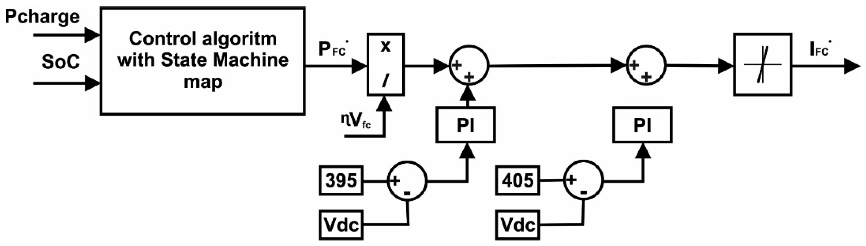
4. Power Management Strategy in a FC/Battery/UC Hybrid System

In order to ensure the efficient operation of the fuel cell (FC), the battery, and the ultracapacitor (UC), while taking into account their constraints, an energy management system is required. The main objectives of the energy management system are
-
to guarantee low hydrogen consumption [24,25,26],
-
to increase the overall system efficiency [27,28],
-
to ensure the battery SoC remains in a narrow operating range [29,30,31,32], and
-
to increase component lifetime [33].
These objectives are achieved by controlling the power flow to each of the three sources in order to meet the load requirements through their associated converters, using a particular energy management strategy (EMS). In the case of the given application, the control strategy was based on a state machine (SM) map strategy [34,35]. The management strategy was designed to meet several requirements: to preserve the fuel cell lifetime by avoiding an insufficient supply of reactants (fuel cell starvation) and by limiting the supplied current rate to a maximum of 40 A/s [17]; for efficient battery system operation, the battery SoC was kept above 60% at all times. The voltage on the DC bus (or UC SoC) was regulated by controlling DC/DC converter 1 of the cell [36,37,38].
The employed control strategy, based on the state machine map, consisted of eight states, as shown in Table 1 and Figure 8. The fuel cell power is determined by the battery state of charge and the required load power (Pload). As shown, the output of the algorithm is the reference for the fuel cell power. Both this quantity relative to the fuel cell voltage and the efficiency of the DC/DC converter lead to the value of the fuel cell reference current. To determine power of fuel cell, we used an emulator. The state of charge is measured by the Control System using a method known as Coulomb counting. Required load power measured torque transducer [39,40,41].

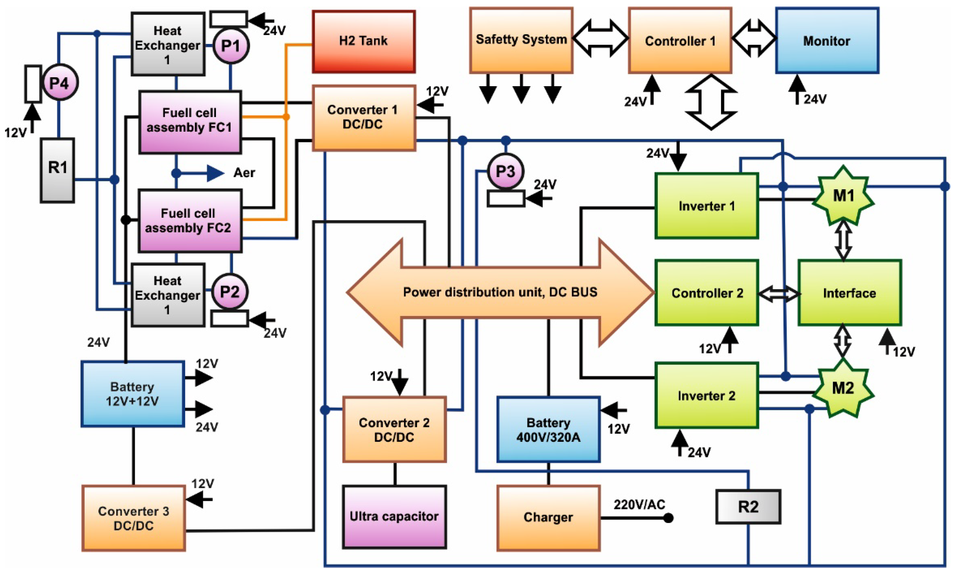
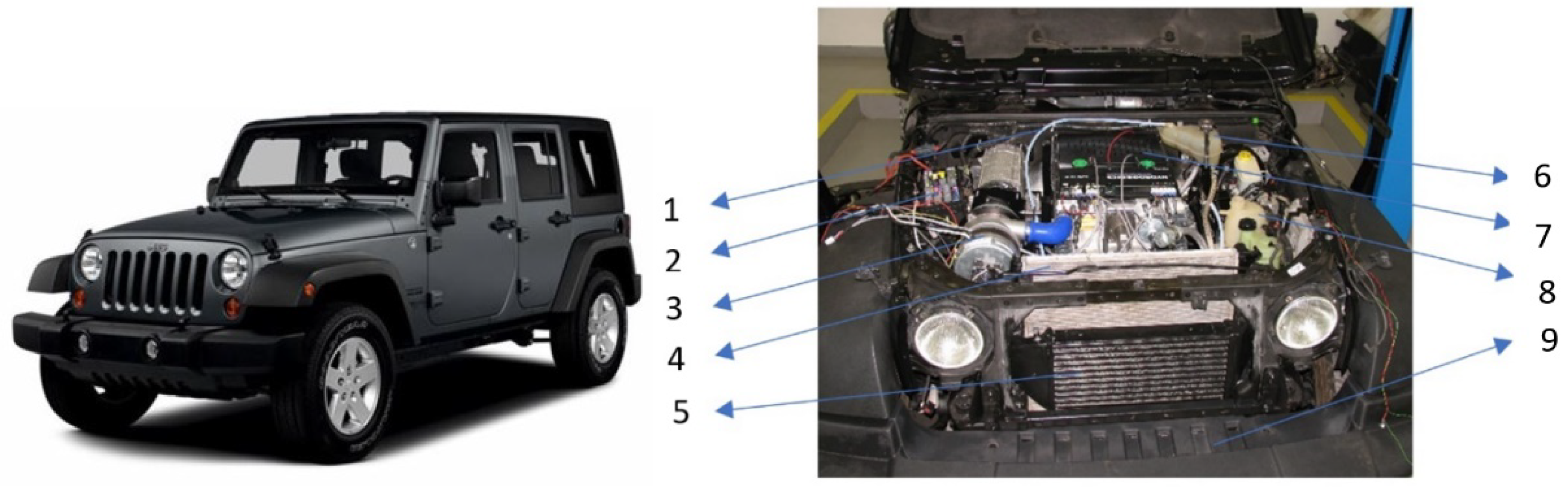
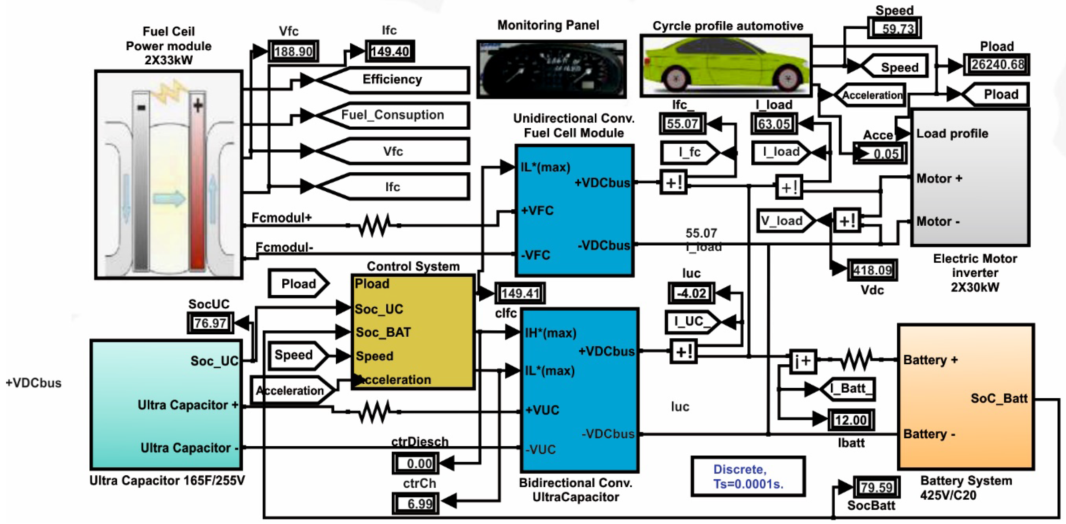
5. Case Study: Electric Vehicle in Fuel Cell/Battery/Ultracapacitor Hybrid Topology

In order to test the simulations described in the previous sections, a case study was performed in which a fuel cell hybrid system was employed in an electric vehicle. The case study vehicle used the body of a Jeep Wrangler, from which the internal combustion engine, its associated subassemblies, and the gearbox were removed. The total weight of the removed equipment was approximately 650 kg, resulting in a body weight of 1200 kg. Figure 9 shows images of the studied vehicle.
The electric propulsion system installed in the vehicle comprised:
  • two fuel cells each with 33 kW of power, connected in a series;
  • a 30 kW rechargeable battery pack;
  • five 48 V and 165 F ultracapacitor units connected in series;
  • a power distribution unit (PDU);
  • a unidirectional converter for connecting the fuel cell to the PDU;
  • a bidirectional converter to connect the ultracapacitor to the PDU;
  • a 24 V auxiliary battery charger (2 × 12 V);
  • a main battery charging module from 230 V (AC);
  • two 33 kW electric motors mounted on the rear wheels;
  • two motor inverters;
  • command and control modules for the propulsion system;
  • two 50 L at 350 bar hydrogen cylinders; and
  • auxiliary equipment (water pumps, vacuum pumps, temperature sensors, hydrogen sensors, etc.).
Figure 10 shows the experimentally determined power distributions of the completed vehicle. Measurements were made using a National Instruments data-acquisition system.
From the experimental results in Figure 10, the following can be mentioned:
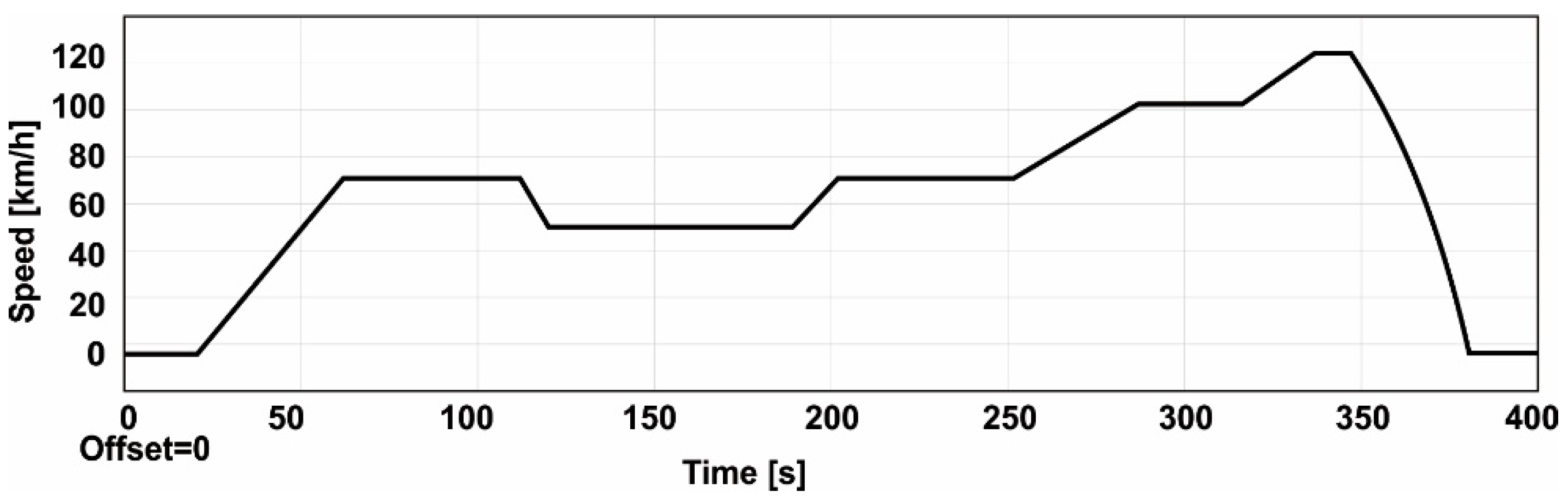
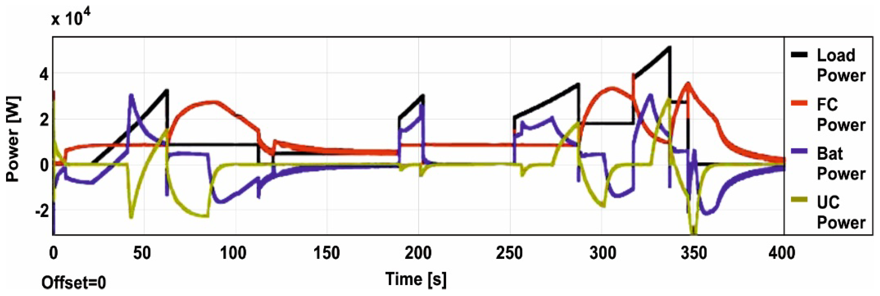
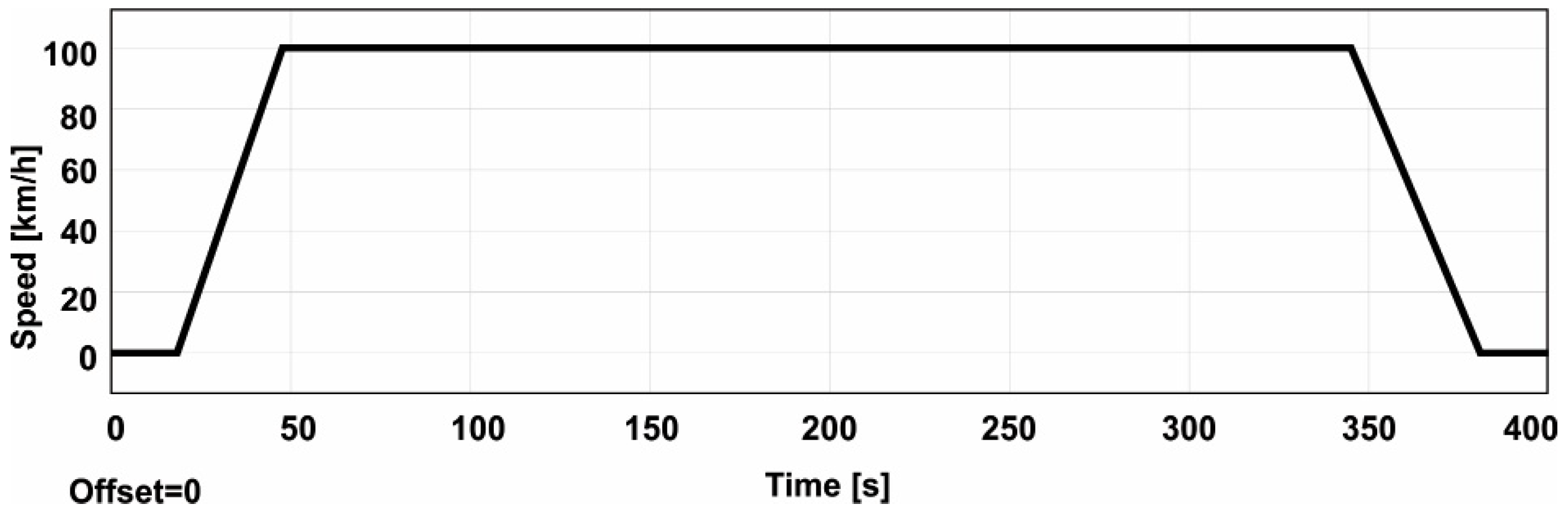
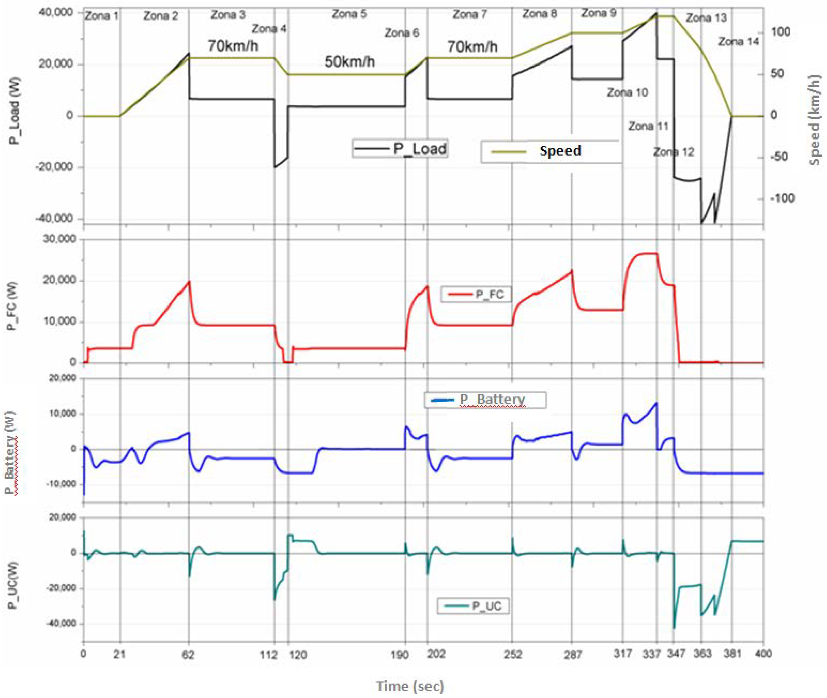
  • The urban cycle driving autonomy was 2 h 20 min at an average speed of 45 km/h.
  • The extra-urban cycle driving autonomy was 2 h 50 min at an average speed of 70 km/h.
  • The maximum imposed speed was 120 km/h.
  • The vehicle, upon departure, reached 100 km/h in 38 s.
Clearly, the tested vehicle performed as expected. The power calculated for simulation of the vehicle was 100 km/h in 30 s and experimental results was 100 km/h in 38 s.
From the beginning, there was a difference in power output between versions resulting from simulations and what is actually performed by the vehicle. In the configuration, real consumption of self-sustaining vehicles mention energy needs for power subassemblies components, pumps circulation of coolant for steering and brake circuits and signaling lights, etc., introduce consumption of significance to be taken into account. Also, a more detailed analysis includes the vehicle power management algorithm, depending on which functional parameters are obtained for the three energy streams, but this is the subject of a work underway, in which different management algorithms are considered [42].

6. Conclusions

This paper presents a study on the implementation of hydrogen fuel cell technologies in electric vehicles. This approach originated because the use of hydrogen as a fuel produces no pollution while providing in-situ power generation through electrochemical conversion. Additionally, hydrogen fuel cells can efficiently convert hydrogen into energy and be used to recharge batteries and ultracapacitors, improving the time between refueling. The results presented here lead to better knowledge of the technology and enable a solution to the practical issue of energy management in a hybrid fuel cell electric vehicle.
The hybrid electric vehicle developed here is not state-of-the-art, but rather, demonstrates the capabilities and functionality of the technology. The result can be considered innovative from the point of view of both the proposed technology and the expected results—the production of a hybrid series car with the ability to travel in traffic with a degree of autonomy is comparable to classic combustion engine vehicles. The power calculated for simulation of the vehicle has 100 km/h in 30 s and in experimental results has 100 km/h in 38 s.
It is likely that at this time, the investment cost of these vehicles is too high when compared to classic vehicles. However, it should be noted that this area is making very rapid progress. For example, the price of a PEM fuel cell has decreased by one third over the past ten years and is expected to be 20% of the current value (per kW) in 2020. Thus, once this technology is ready for deployment in real scenarios, the costs will be competitive. In addition, the economic advantage of the proposed solution is its versatility in employing hydrogen fuel cells in vehicles in several ways, each being suited to particular conditions and subject to the provisions of national standards and regulations.

Author Contributions

I.A.—Concept, Edit paper, State-of-the-arts, Case study, Conclusions; M.V.—Simulations; M.C.—State-of-the-arts, Power management strategy; M.I.—Block Diagram; M.R.—Simulating of the electric vehicle powertrain; A.E.—Control strategy; M.S.R.—Edit paper, Simulation; G.R.—Structure and operating principles, Conclusions; C.F.—Concept, Control strategy, Simulations.

Acknowledgments

This work was supported by a grant of the Romanian Ministery of Research and Innovation, CCCDI-UEFISCDI, project number PN-III-P1-1.2-PCCDI-2017-0776/No. 36 PCCDI/15.03.2018, within PNCDI III.

Conflicts of Interest

The authors declare no conflict of interest.

References

  1. Larminie, J.; Dicks, A. Fuel Cell Systems Explained, 2nd ed.; Wiley & Sons Ltd.: Chichester, UK, 2003. [Google Scholar]
  2. Balat, M. Potential importance of hydrogen as a future solution to environmental and transportation problems. Int. J. Hydrogen Energy 2008, 33, 4013–4029. [Google Scholar] [CrossRef]
  3. European Economic Area. Renewable Energy in Europe 2016; European Environment Agency, EU Publication: Copenhagen, Denmark, 2016. [Google Scholar] [CrossRef]
  4. Dincer, I.; Acar, C. Review and evaluation of hydrogen production methods for better sustainability. Int. J. Hydrogen Energy 2015, 40, 11094–11111. [Google Scholar] [CrossRef]
  5. Piela, P.; Mitzel, J. Polymer electrolyte membrane fuel cell efficiency at the stack level. J. Power Sources 2015, 292, 95–103. [Google Scholar] [CrossRef]
  6. Pavelka, M.; Marsik, F. Detailed thermodynamic analysis of polymer electrolyte membrane fuel cell efficiency. Int. J. Hydrogen Energy 2013, 38, 7102–7113. [Google Scholar] [CrossRef]
  7. Hwang, J.-J. Effect of hydrogen delivery schemes on fuel cell efficiency. J. Power Sources 2013, 239, 54–63. [Google Scholar] [CrossRef]
  8. Das, H.S.; Tan, C.W.; Yatim, A.H.M. Fuel cell hybrid electric vehicles: A review on power conditioning units and topologies. Renew. Sustain. Energy Rev. 2017, 76, 268–291. [Google Scholar] [CrossRef]
  9. Ahmadi, S.; Bathaee, S.M.T.; Hosseinpour, A.H. Improving fuel economy and performance of a fuel-cell hybrid electric vehicle (fuel-cell, battery, and ultra-capacitor) using optimized energy management strategy. Energy Convers. Manag. 2018, 160, 74–84. [Google Scholar] [CrossRef]
  10. Munteanu, R.; Cimpeanu, A.; Graur, A.; Filote, C.; Liuba, G. Quasi-stationary and Transient Regime of Induction Machine Supplied by Two Stator Frequencies. Adv. Electr. Comput. Eng. 2014, 14, 131–136. [Google Scholar] [CrossRef]
  11. Song, Z.; Zhang, X.; Li, J.; Hofmann, H.; Ouyang, M.; Du, J. Component sizing optimization of plug-in hybrid electric vehicles with the hybrid energy storage system. Energy 2018, 144, 393–403. [Google Scholar] [CrossRef]
  12. Ruan, J.; Walker, P.D.; Zhang, N.; Wu, J. An investigation of hybrid energy storage system in multi-speed electric vehicle. Energy 2017, 140, 291–306. [Google Scholar] [CrossRef]
  13. Bizon, N. A new topology of fuel cell hybrid power source for efficient operation and high reliability. J. Power Sources 2011, 196, 3260–3270. [Google Scholar] [CrossRef]
  14. Wang, G.; Huang, F.; Yu, Y.; Wen, S.; Tu, Z. Degradation behavior of a proton exchange membrane fuel cell stack under dynamic cycles between idling and rated condition. Int. J. Hydrogen Energy 2018, 43, 4471–4481. [Google Scholar] [CrossRef]
  15. Gazdzick, P.; Mitzel, J.; Garcia Sanchez, D.; Schulze, M.; Friedrich, K.A. Evaluation of reversible and irreversible degradation rates of polymer electrolyte membrane fuel cells tested in automotive conditions. J. Power Sources 2016, 327, 86–95. [Google Scholar] [CrossRef]
  16. Dafalla, A.M.; Jiang, F. Stresses and their impacts on proton exchange membrane fuel cells: A review. Int. J. Hydrogen Energy 2018, 43, 2327–2348. [Google Scholar] [CrossRef]
  17. Fletcher, T.; Thring, R.; Watkinson, M. An Energy Management Strategy to concurrently optimise fuel consumption & PEM fuel cell lifetime in a hybrid vehicle. Int. J. Hydrogen Energy 2016, 41, 21503–21515. [Google Scholar] [CrossRef]
  18. Marzougui, H.; Amari, M.; Kadri, A.; Bacha, F.; Ghouili, J. Energy management of fuel cell/battery/ultracapacitor in electrical hybrid vehicle. Int. J. Hydrogen Energy 2017, 42, 8857–8869. [Google Scholar] [CrossRef]
  19. Bizon, N.; Oproescu, M.; Raceanu, M. Efficient energy control strategies for a Standalone Renewable/Fuel Cell Hybrid Power Source. Energy Convers. Manag. 2015, 90, 93–110. [Google Scholar] [CrossRef]
  20. Bizon, N. Real-time optimization strategy for fuel cell hybrid power sources with load-following control of the fuel or air flow. Energy Convers. Manag. 2018, 157, 13–27. [Google Scholar] [CrossRef]
  21. Zhou, D.; Ravey, A.; Al-Durra, A.; Gao, F. A comparative study of extremum seeking methods applied to online energy management strategy of fuel cell hybrid electric vehicles. Energy Convers. Manag. 2017, 151, 778–790. [Google Scholar] [CrossRef]
  22. Ravey, A.; Watrin, N.; Blunier, B.; Bouquain, D.; Miraoui, A. Energy—Source-sizing methodology for hybrid fuel cell vehicles based on statistical description of driving cycles. IEEE Trans. Veh. Technol. 2012, 60, 4164–4174. [Google Scholar] [CrossRef]
  23. Liu, C.; Liu, L. Optimal power source sizing of fuel cell hybrid vehicles based on Pontryagin’s minimum principle. Int. J. Hydrogen Energy 2015, 40, 8454–8464. [Google Scholar] [CrossRef]
  24. Zhang, W.; Li, J.; Xu, L.; Ouyang, M. Optimization for a fuel cell/battery/capacity tram with equivalent consumption minimization strategy. Energy Convers. Manag. 2017, 134, 59–69. [Google Scholar] [CrossRef]
  25. Fernandez, R.A.; Caraballo, S.C.; Cilleruelo, F.B.; Lozano, J.A. Fuel optimization strategy for hydrogen fuel cell range extender vehicles applying genetic algorithms. Renew. Sustain. Energy Rev. 2018, 81 Pt 1, 655–668. [Google Scholar] [CrossRef]
  26. Bravo, J.; Ribau, J.; Silva, C. The influences of energy storage and energy management strategies on fuel consumption of a fuel cell hybrid vehicle. IFAC Proc. Vol. 2012, 45, 233–240. [Google Scholar] [CrossRef]
  27. Bizon, N. Energy efficiency for the multiport power converters architectures of series and parallel hybrid power source type used in plug-in/V2G fuel cell vehicles. Appl. Energy 2013, 102, 726–734. [Google Scholar] [CrossRef]
  28. Hu, X.; Murgovski, N.; Johannesson, L.; Egardt, B. Energy efficiency analysis of a series plug-in hybrid electric bus with different energy management strategies and battery sizes. Appl. Energy 2013, 111, 1001–1009. [Google Scholar] [CrossRef]
  29. Opitz, A.; Badami, P.; Shen, L.; Vignarooban, K.; Kannan, A.M. Can Li-Ion batteries be the panacea for automotive applications? Renew. Sustain. Energy Rev. 2017, 68 Pt 1, 685–692. [Google Scholar] [CrossRef]
  30. Ruiz, V.; Pfrang, A.; Kriston, A.; Omar, N.; Van den Bossche, P.; Boon-Brett, L. A review of international abuse testing standards and regulations for lithium ion batteries in electric and hybrid electric vehicles. Renew. Sustain. Energy Rev. 2018, 81, 1427–1452. [Google Scholar] [CrossRef]
  31. Li, Z.; Huang, J.; Liaw, B.Y.; Zhang, J. On state-of-charge determination for lithium-ion batteries. J. Power Sources 2017, 348, 281–301. [Google Scholar] [CrossRef]
  32. Hannan, M.A.; Lipu, M.S.H.; Hussain, A.; Mohamed, A. A review of lithium-ion battery state of charge estimation and management system in electric vehicle applications: Challenges and recommendations. Renew. Sustain. Energy Rev. 2017, 78, 834–854. [Google Scholar] [CrossRef]
  33. Han, J.; Park, Y.; Park, Y.-S. A novel updating method of equivalent factor in ECMS for prolonging the lifetime of battery in fuel cell hybrid electric vehicle. IFAC Proc. Vol. 2012, 45, 227–232. [Google Scholar] [CrossRef]
  34. Li, Q.; Yang, H.; Han, Y.; Li, M.; Chen, W. A state machine strategy based on droop control for an energy management system of PEMFC-battery-supercapacitor hybrid tramway. Int. J. Hydrogen Energy 2016, 41, 16148–16159. [Google Scholar] [CrossRef]
  35. Lai, C.M.; Yang, M.J. A High-Gain Three-Port Power Converter with Fuel Cell, Battery Sources and Stacked Output for Hybrid Electric Vehicles and DC-Microgrids. Energies 2016, 9, 180. [Google Scholar] [CrossRef]
  36. Aschilean, I.; Rasoi, G.; Raboaca, M.S.; Filote, C.; Culcer, M. Design and Concept of an Energy System Based on Renewable Sources for Greenhouse Sustainable Agriculture. Energies 2018, 11, 1201. [Google Scholar] [CrossRef]
  37. Tribioli, L. Energy-Based Design of Powertrain for a Re-Engineered Post-Transmission Hybrid Electric Vehicle. Energies 2017, 10, 918. [Google Scholar] [CrossRef]
  38. Sim, K.; Oh, S.-M.; Kang, K.-Y.; Hwang, S.-H. A Control Strategy for Mode Transition with Gear Shifting in a Plug-In Hybrid Electric Vehicle. Energies 2017, 10, 1043. [Google Scholar] [CrossRef]
  39. Ott, T.; Onder, C.; Guzzella, L. Hybrid-Electric Vehicle with Natural Gas-Diesel Engine. Energies 2013, 6, 3571–3592. [Google Scholar] [CrossRef]
  40. Solouk, A.; Shahbakhti, M. Energy Optimization and Fuel Economy Investigation of a Series Hybrid Electric Vehicle Integrated with Diesel/RCCI Engines. Energies 2016, 9, 1020. [Google Scholar] [CrossRef]
  41. Han, Y.; Chen, W.; Li, Q. Energy Management Strategy Based on Multiple Operating States for a Photovoltaic/Fuel Cell/Energy Storage DC Microgrid. Energies 2017, 10, 136. [Google Scholar] [CrossRef]
  42. Odeim, F.; Roes, J.; Heinzel, A. Power Management Optimization of an Experimental Fuel Cell/Battery/Supercapacitor Hybrid System. Energies 2015, 8, 6302–6327. [Google Scholar] [CrossRef]
Figure 1. Block diagram for the chosen configuration. The system includes several water recirculation pumps (P1–P4), fan radiators (R1, R2), and two wheel-mounted engines (M1, M2). The orange track represents hydrogen-pulled, blue track represents cooling fluid, and black track represents —energy. Orange boxes are DC/DC converters and controller, blue boxes are batteries, green boxes are inverters and Powertrain System, magenta boxes are fuel cells and ultracapacitor, and the red box represents a hydrogen tank.
Energies 11 01294 g001
Figure 2. Current distribution for the three directly connected power flows.
Energies 11 01294 g002
Figure 3. The complete model for powertrain simulation.
Energies 11 01294 g003
Figure 4. Vehicle speed profile for the European extra-urban driving cycle (EUDC).
Energies 11 01294 g004
Figure 5. Power profile for the load (black) and the three system components—the fuel cell (FC, red); the battery (Bat, blue) and the ultracapacitor bank (UC, yellow)—on the DC Bus for load power demand coverage on the EUDC.
Energies 11 01294 g005
Figure 6. Vehicle speed profile to accelerate to 100 km/h from rest in 30 s.
Energies 11 01294 g006
Figure 7. Power profile for the load (black) and the three system components—the fuel cell (FC, red); the battery (Bat, blue) and the ultracapacitor bank (UC, yellow)—on the DC Bus for coverage of power demand on the load for an acceleration cycle from rest to 100 km/h in 30 s.
Energies 11 01294 g007
Figure 8. Control strategy based on the State Machine map.
Energies 11 01294 g008
Figure 9. Electric vehicle in hybrid topology. 1 indicates PEM fuel cells hydrogen supply system, 2 indicates command and control system, 3 indicates PEM fuel cells air supply system, 4 indicates primary cooling radiator, 5 indicates secondary cooling radiator, 6 indicates cooling agent storage vessel, 7 indicates PEM fuel cells stack, 8 indicates coolant agent expansion tank, and 9 indicates car bodywork.
Energies 11 01294 g009
Figure 10. Power distribution for state machine control strategy in the case study vehicle.
Energies 11 01294 g010
Table 1. State Machine Map. The inputs are the battery state of charge (SoC) and the load power (Pload). Additional parameters include the maximum, minimum, and optimum fuel cell power (Pfc); and the charging power Pcharge.
If SoC > 90 & Pload < PfcminStatus = 1Pfc = Pfcmin
If SoC > 90 & Pload ϵ [Pfcmin, Pfcmax]Status = 2Pfc = Pload
If SoC > 90 & Pload ≥ Pfcmax Status = 3Pfc = Pfcmax
If SoC ϵ [65.85] & Pload < PfcoptStatus = 4Pfc = Pfcopt
If SoC ϵ [65.85] & Pload ϵ [Pfcopt, Pfcmax]Status = 5Pfc = Pload
If SoC ϵ [65.85] & Pload ≥ PfcmaxStatus = 6Pfc = Pfcmax
If SoC < 60 & Pload < PfcmaxStatus = 7Pfc = Pload + Pcharge
If SoC < 60 & Pload ≥ PfcmaxStatus = 8Pfc = Pfcmax

