Article

An Integrated Current-Voltage Compensator Design Method for Stable Constant Voltage and Current Source Operation of LLC Resonant Converters

The Department of Electrical and Biomedical Engineering, Hanyang University, Seoul 04763, Korea
*
Author to whom correspondence should be addressed.
Energies 2018, 11(6), 1325; https://doi.org/10.3390/en11061325
Submission received: 27 April 2018 / Revised: 18 May 2018 / Accepted: 21 May 2018 / Published: 23 May 2018
(This article belongs to the Special Issue Power Electronics 2018)

Abstract

:
This paper proposes a method to charge a lithium ion battery with an integrated compensator. Unlike the conventional charging method which uses separate voltage/current compensators based on a constant voltage-constant current charge profile, the proposed method uses a single compensator. The conventional method requires a complicated design process such as separate plant modeling for compensator design and the compensator tuning process in the frequency domain. Moreover, it has the disadvantage of a transient state between the mode change. However, the proposed method simplifies the complicated process and eliminates the transient response. The proposed compensator is applied to the LLC resonant converter and is designed to provide smooth and reliable performance during the entire charging process. In this paper, for the compensator design, the frequency domain models of the LLC resonant converter at the constant voltage and constant current charging mode are derived including the impedance model of the battery pack. Additionally, the worst condition of the compensator design during the entire charging process is considered. To demonstrate the effectiveness of the proposed method, the theoretical design procedure is presented in this paper, and it is verified through experimental results using a 300 W LLC converter and battery pack.

1. Introduction

As the demand for energy storage and renewable energy systems grows rapidly, batteries are playing important roles. In particular, lithium-ion (Li-ion) batteries have no memory effect, high energy density, and low self-discharge effects, making them suitable for a variety of applications, from small portable devices to electric vehicles. This trend has also increased the importance of Li-ion battery chargers and charging methods [1,2].
Battery chargers were designed using a variety of pulse width modulation (PWM) converters, including buck and fly-back converters. However, the importance of high power density and high efficiency operation has recently been emphasized, and LLC resonator converters research is also actively underway. The LLC resonant converter is capable of high-switching frequency operation and high-efficiency operation because it performs zero voltage switching under the entire load condition [3,4,5]. In addition, since the leakage inductance of the transformer is used as a resonant inductor, there is an advantage in terms of cost and power density [6].
On the other hand, studies on the charging method have been actively carried out for efficient and stable charging of Li-ion batteries [7,8,9,10,11,12]. In Ref. [7,8,9], the optimum charging pattern of a Li-ion battery is proposed which computes the cost function based on hardware/software setup to increase the charging efficiency and charge the Li-ion battery in a short time. Another previous study [8] proposed a method of detecting the lowest impedance of a battery and charging it with a pulse of the corresponding frequency for quick charging. Other previous studies [10,11,12] established the equivalent circuit model of the battery and proposed the optimal charging pattern. However, the above methods have limitations in terms of cost, volume, and the complexity to be applied to the battery charger. Therefore, in industry, the constant current and constant voltage (CC-CV) charging method which has a relatively simple operation and robust characteristics is widely used among the aforementioned methods [13].
In this method, when the voltage of the battery pack is lower than the full charge voltage, the charger is operated as a constant current source to prevent overcurrent charging, and when the full charge voltage is reached, the charger is operated as a constant voltage source. The CC-CV charging method has the advantage that it can guarantee the state of charge (SOC) of the battery up to 100%. However, since the output current and voltage of the charger have a wide range of variation during the whole charging process, it is difficult to select the worst case condition for compensator design. Moreover, in general, as in previous literature [14], the compensator for constant current charging and the compensator for constant voltage charging are separated. Therefore, there is a disadvantage that a transient state exists at the change of charging mode.
Conventional studies using constant-current and constant-voltage charging methods for LLC resonant converters have presented various solutions to solve these problems [15,16,17,18,19]. However, many studies have attempted hardware modifications to meet wide output voltage and output current ranges or have focused only on selecting optimal circuit parameters [16,17,18].
Although there have been studies on compensator design considering the dynamic characteristics of the LLC resonant converter, it is difficult to guarantee stable operation during the entire charging period without considering the worst condition when designing the compensator. Still, the separated voltage and current compensator has been adopted and the transient state exists at the time of mode switching [19,20,21,22].
In previous research [18,19,23], the compensator was designed by modeling the battery as an equivalent resistance. However, it cannot reflect all the dynamic characteristics of the battery, so it is difficult to guarantee stable operation in various situations. Previous studies [24,25] for eliminating the transient state during mode switching have removed the transient state through adopting additional circuitry. However, the disadvantage is that the complexity increases due to the additional hardware.
In this paper, the integrated voltage and current compensator of a battery charger based on the LLC resonant converter is proposed and the design method for solving the above problems is presented. The design of the proposed compensator is based on the model of the LLC resonant converter obtained by using the extended describing function and the frequency domain model of the Li-ion battery pack obtained by using a frequency analyzer. Since the proposed method uses only one compensator unlike the conventional separated compensator, it is possible to simplify the compensator design procedure, and it is possible to eliminate the transient state during the mode change without an additional circuit. Moreover, it does not require separate hardware setups or complex algorithms, making it easy to apply to a variety of applications. In addition, since the compensator is designed considering the worst operating condition by comparing the stability of the system in the entire charging area, stable operation is ensured in the entire charging area. The proposed method is explained in detail through a 300 W battery charger design example and its effectiveness is verified through experiments.

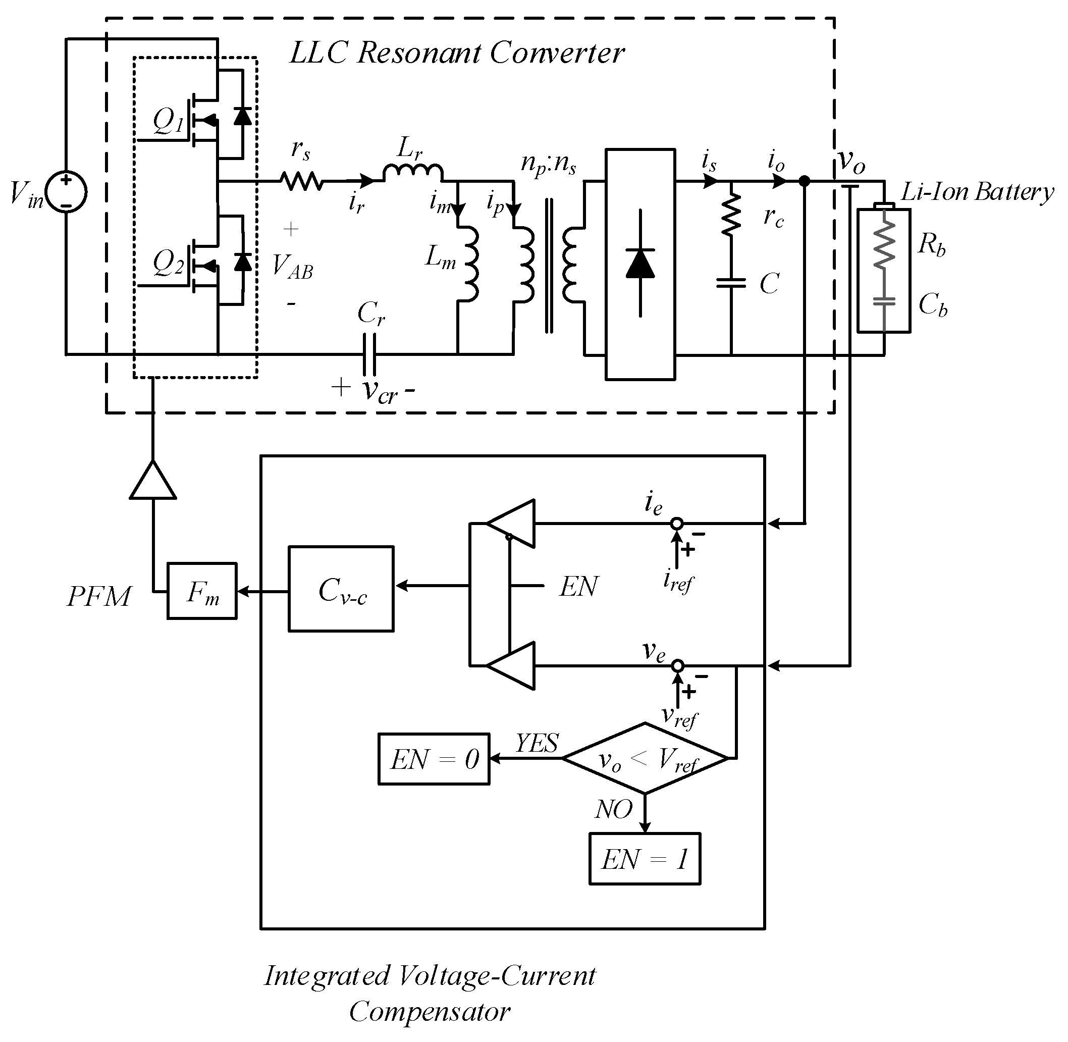
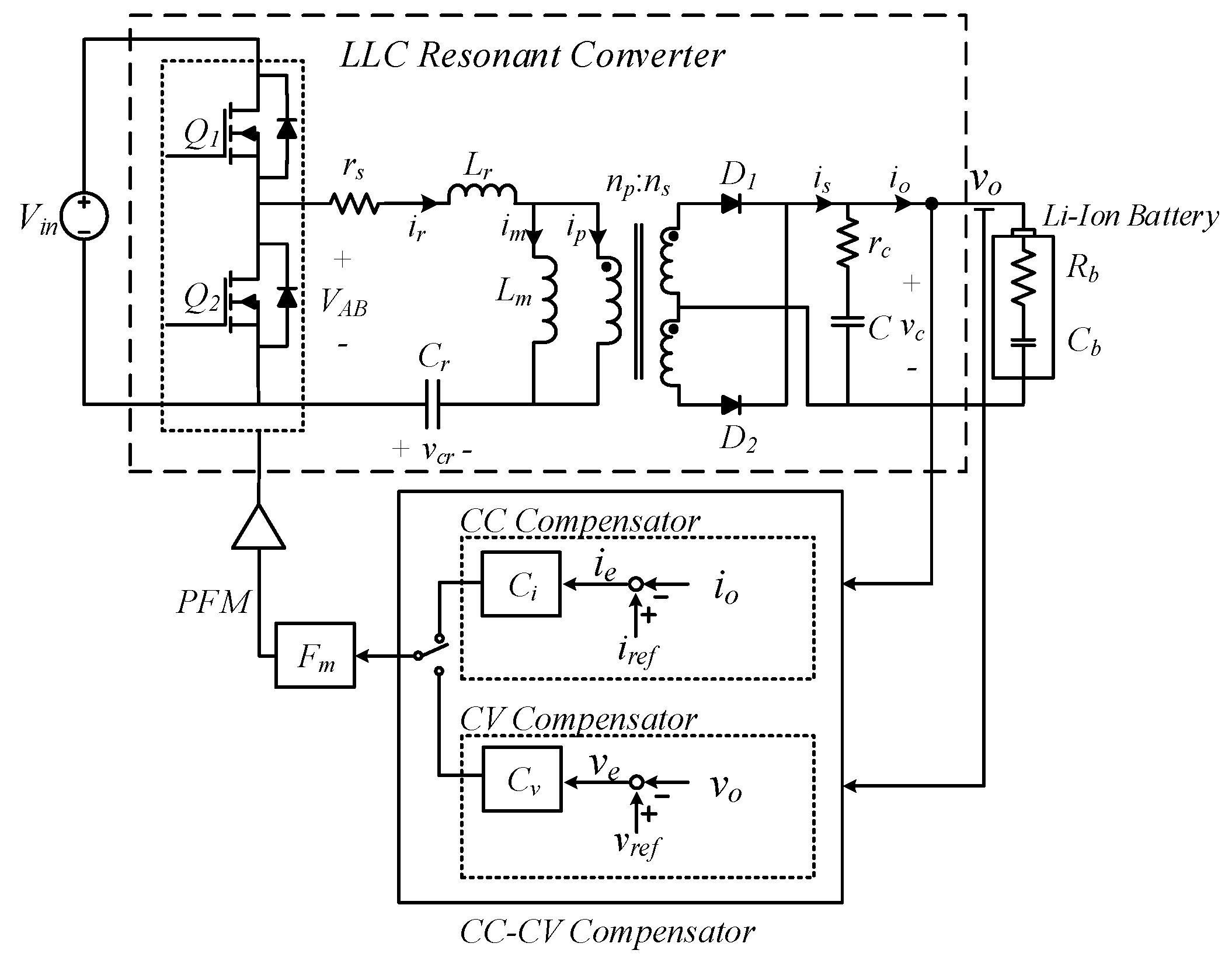
2. LLC Resonant Converter-Based Battery Charger

2.1. System Description

Figure 1 shows a circuit of a half bridge LLC resonant converter battery charger and a Li-ion battery where Lm is the magnetizing inductor, Lr is the resonant inductor, Cr is the resonant capacitor, np and ns are the primary and secondary transformer windings, respectively, Q1 and Q2 are the switches, Fm is the pulse frequency modulator, rs is the resonant tank parasitic resistance, D1 and D2 denote rectifying diodes, and C and rc denote the output capacitor and equivalent series resistor of C. ir, iLm, ip, is, io, and vo are the resonant current, the magnetizing current, the primary transformer current, the rectified secondary current, the output current, and the output voltage, respectively.
The LLC resonant converter consists of a switch network, a resonant network, and a rectifying network on the secondary side [26]. The switch network performs complementary switching with a duty ratio of 50%, and the resonant network consists of resonant capacitors, resonant inductors, and magnetizing inductors of the transformer where the resonant inductor can be integrated into the leakage inductance of the transformer.
The rectifying network of the LLC resonant converter serves to smoothen the output voltage to the secondary side by using a rectifying diode and an output capacitor. In the case of a battery charger application in which a large current flows in the rectifying network, a center tap structure is mainly adopted to reduce conduction loss.
For constant current-constant voltage charging, a current compensator and a voltage compensator are required, as shown in Figure 1. Constant current charging is performed where the battery pack voltage is higher than the cutoff voltage and lower than the full charge voltage. During the charging process, the compensator maintains the output current through the switching frequency adjustment so that the error ie between the detected io and the current reference iref decreases. When the voltage of the battery pack becomes equal to the full charge voltage, the constant current charging is terminated and the constant voltage charging starts. During the constant voltage charging, the voltage compensator maintains the output voltage through the switching frequency adjustment so that the error ve between the detected vo and the voltage reference vref decreases. If the charge current during constant voltage charging is less than the predetermined cutoff current value, IT, the charging process is terminated.

2.2. Li-Ion Battery Pack Modeling

The equivalent resistance modeling of the Li-ion battery used in previous research [18,19,23] has been derived based on the output voltage and current of the LLC converter, so it does not reflect the exact dynamic characteristics of the Li-ion battery pack. Therefore, in this paper, a more accurate battery model is obtained through frequency domain analysis of an actual battery pack. The lithium-ion battery consists of 4 parallel and 10 serial connections of the INR18650-29E cell manufactured by SAMSUNG SDI (Gyeonggi Province, Korea). Figure 2 shows the frequency analysis results of the Li-ion battery pack obtained from the frequency analyzer at the nominal voltage.
The approximated magnitude and phase of the analyzed battery pack in the frequency domain are shown in Figure 3. In this paper, assuming that the crossover frequency of the CC-CV compensator is near 100 Hz, approximation is performed while ignoring frequency components more than 10 times the crossover frequency. Equation (1) shows this relationship and it is represented by a series-connected resistor and capacitor. The values of the approximated elements are 87.02 mΩ and 28.73 F, respectively.
G b a t t   ( s ) = 0.034807   1 + 2.5 s s

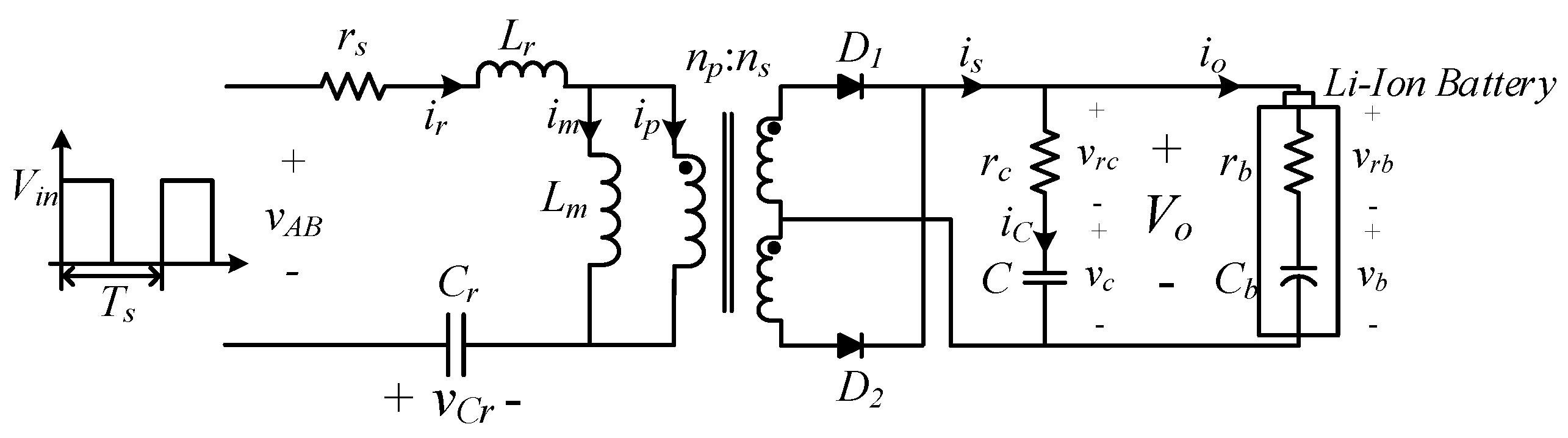
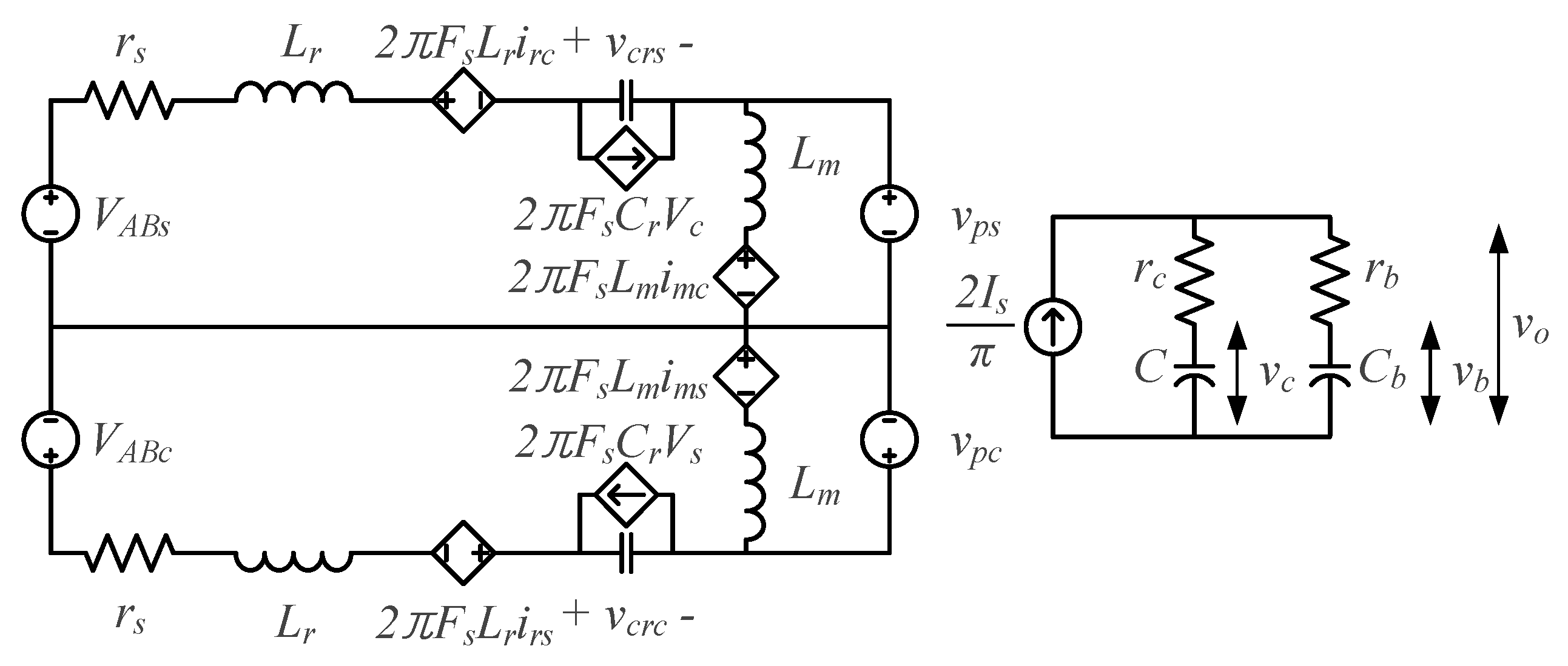
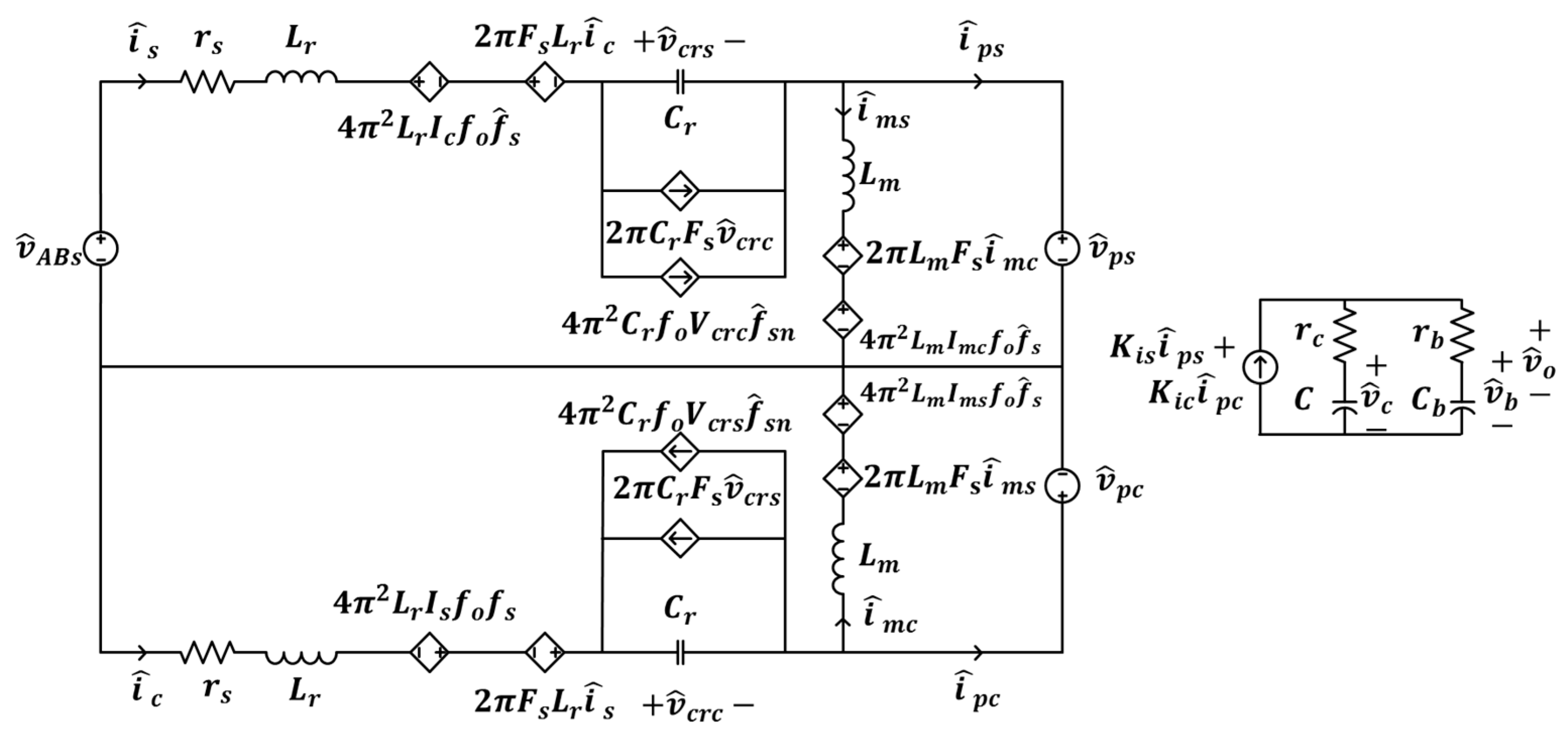
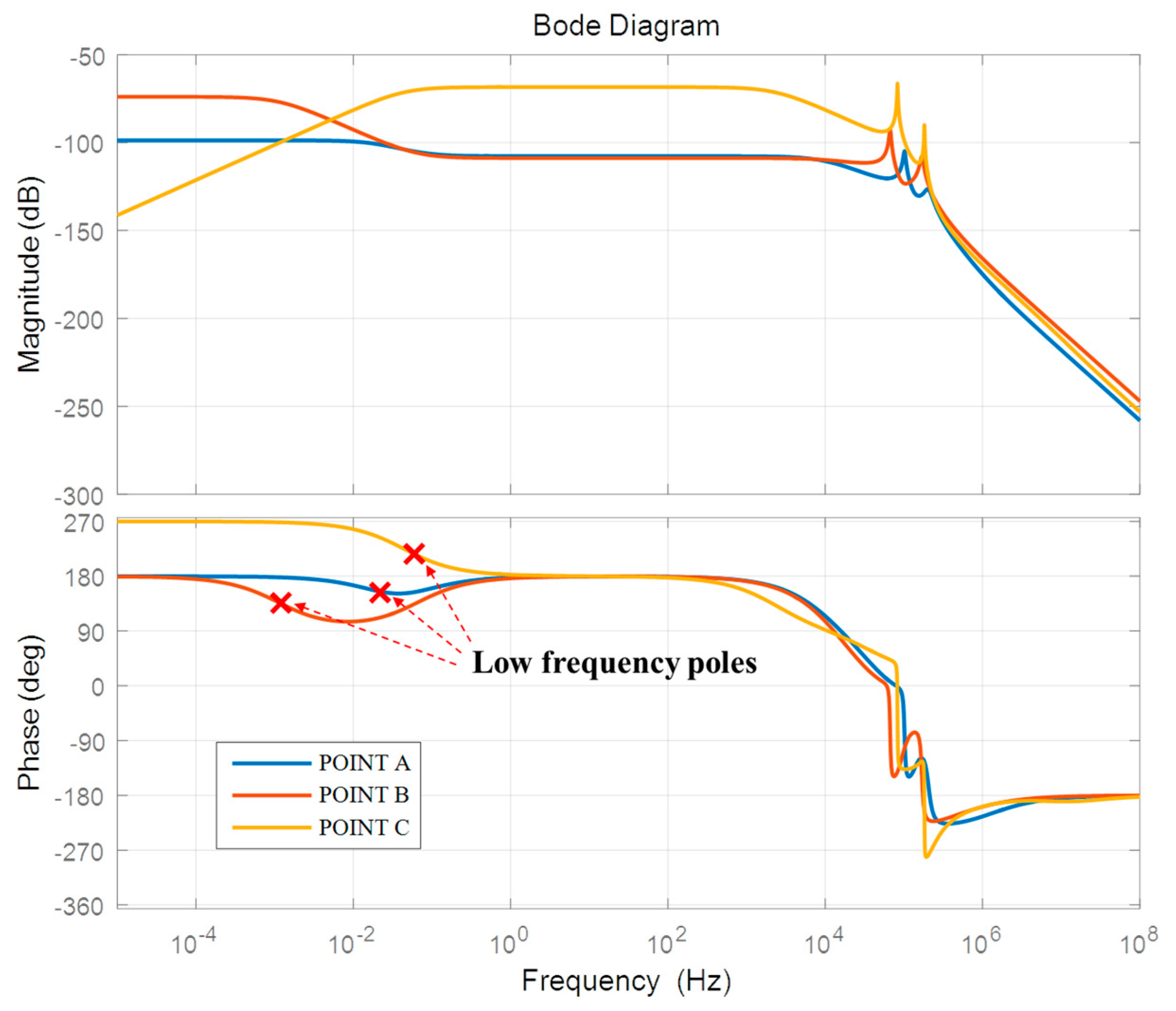
2.3. Modeling of LLC Resonant Converter-Based Battery Chargers

Modeling of the LLC resonant converter-based battery charger is based on the method used in previous studies [27,28,29,30], in which the voltage and current components in the circuit are divided into sine and cosine components. Figure 4 is an equivalent circuit of an LLC resonant converter that simplifies the switch network to a square wave and the approximated battery pack model where VAB is the square wave applied to the resonance tank, vcr is the resonant capacitor voltage, vrc is the voltage applied to the parasitic resistance of the output capacitor, vC is the voltage applied to the output capacitor, and vb and vrb represent voltages applied to rb and Cb included in the approximated battery model. When Kirchhoff’s voltage law (KVL) is applied to the resonant tank, vAB is expressed as follows:
v A B = i r r s + L r ( d i r d t ) + v c r + s g n ( i p ) n V o
Resonant current ir is expressed as follows:
i r = C r ( d v c r d t )
Additionally, n represents the turns ratio and is expressed as follows
n = n p n s
sgn represents the signum function that determines the polarity according to the direction of the current flowing in the primary transformer.
s g n ( i p ) = { 1 f o r i p < 0 1 f o r i p 0
The voltage applied to the primary magnetization inductor is as follows.
v L m = L m d i L m d t = n V o { s g n ( i p ) }
Applying KCL to the output capacitor node, the rectified secondary current is expressed as Equation (7).
i s = i c + i o
The output voltage is expressed as Equation (8) and is the same as Equation (9).
v o = v c + r c ( i s i o )
v o = ( v c + r c i s + r c r b v b ) r b r b + r c
Similarly, the output current is expressed as Equation (10).
i o = ( v c + r c i s v b ) 1 r b + r c
In order to separate the resonant current and voltage into fundamental sine and cosine components, by using the harmonic approximation, the resonant current, resonant capacitor voltage, and magnetizing inductor current are expressed as Equations (11)–(13). The differentiation result of Equations (11)–(13) is Equations (14)–(16) where the subscript s represents the sine component and c represents the cosine component.
i r = i r s sin ( 2 π f s t ) i r c cos ( 2 π f s t )
v c r = v c r s sin ( 2 π f s t ) v c r c cos ( 2 π f s t )
i m = i m s sin ( 2 π f s t ) i m c cos ( 2 π f s t )
d i r d t = ( d i r s d t + 2 π f s i r c ) sin ( 2 π f s t ) ( d i r c d t 2 π f s i r s ) cos ( 2 π f s t )
d v c r d t = ( d v c r s d t + 2 π f s v c r c ) sin ( 2 π f s t ) ( d v c r c d t 2 π f s v c r s ) cos ( 2 π f s t )
d i m d t = ( d i m s d t + 2 π f s i m c ) sin ( 2 π f s t ) ( d i m c d t 2 π f s i m s ) cos ( 2 π f s t )
The result of applying the extended description function (EDF) to vAB, which is the voltage applied to the resonance tank, is as follows, where the function f is the result of applying EDF and the constants in parentheses are the harmonic coefficients at state variables [29,30]:
v A B f 1 ( d ,   v i n ) sin ( 2 π f s t )
f1() is as follows, where d is the effective duty, excluding the dead time θ:
f 1 ( d ,   v i n ) = 2 2 π θ π θ v i n sin ( 2 π f s t ) d ( 2 π f s ) t = 2 v i n π sin ( π 2 d )
Applying EDF to the voltage applied to the primary transformer is as follows, where ipp denotes the rms value of the primary transformer current:
s g n ( i p ) n V o = f 2 ( i p s ,   i p p ,   v L m ) sin ( 2 π f s t ) f 3 ( i p c ,   i p p ,   v L m ) cos ( 2 π f s t ) where ,   f 2 ( i p s ,   i p p ,   v L m ) = 4 n π i p s i p p V o ,   f 3 ( i p c ,   i p p ,   v L m ) = 4 n π i p c i p p V o ,   i p p = i p s 2 + i p c 2
In order to derive the operating point of the LLC resonant converter based on the abovementioned relation, the following Equation (20) is obtained by solving only the sine component by substituting Equations (11) and (19) into Equation (2). Also, Equation (21) is obtained by solving only the cosine component in the same manner. Similarly, by substituting Equation (12) into Equation (3), the separated sine component is as shown in Equation (22) and the separated cosine component is as shown in Equation (23). Finally, Equations (24) and (25) are derived by substituting Equation (13) into Equation (6) and separating only the sine and cosine components respectively, where the sine component of the magnetizing inductor current is defined as vps and the cosine component is vpc.
v A B s = L r ( d i r s d t + 2 π f s i r c ) + i r s r s + v c r s + 4 n π i p s i p p V o
v A B c = L r ( d i r c d t 2 π f s i r s ) + i r c r s + v c r c + 4 n π i p c i p p V o
i r s = C r ( d v c r s d t + 2 π f s v c r c )
i r c = C r ( d v c r c d t 2 π f s v c r s )
v m s = L m ( d i m s d t + 2 π f s i m c ) = 4 n π i p s i p p V o = v p s
v m c = L m ( d i m c d t 2 π f s i m s ) = 4 n π i p c i p p V o = v p c
In contrast, to derive the operating point, only by calculating the DC value of the rectified secondary current and substituting into Equations (7) and (8), Equations (26) and (27) are obtained where the resistance rc is defined in Equation (28).
i o = r c r b r c ( r c 2 I s π + v c v b )
v o = r c ( 2 I s π + v c r c v b r b )
r c = r b r c r b + r c
Considering only the DC components of Equations (20) and (21), the relationships are expressed as follows, where the equivalent resistance Re is defined as shown in Equation (31).
v A B s = L r ( 2 π F s I r c ) + ( r s + R e ) I r s + v c r s R e I m s
v A B c = L r ( 2 π F s I r s ) + ( r s + R e ) I r c + v c r c R e I m c
R e = 8 n 2 π 2 V o I o
Considering only the DC components of Equations (22) and (23), the relationships are expressed as follows:
I r s = C r ( 2 π F s v c r c )
I r c = C r ( 2 π F s v c r s )
Considering only the DC components of Equations (24) and (26), the relationships are expressed as follows:
R e I s L m 2 π F s I m c R e I m s = 0
R e I c + L m 2 π F s I m s R e I m c = 0
The sine component IPS and the cosine component IPC of the current flowing in the primary transformer are expressed as:
I p s = I r s I m s
I p c = I r c I m c
The equivalent large-signal model reflecting the above relations is shown in Figure 5. Since VAB, the voltage applied to the resonance tank, is an odd function, VABC is 0 by using the Fourier series, and the large-signal model reflecting the relationships including Equations (29)–(37) is as follows, where U is the input matrix, Y is the output matrix, and X is the variable matrix:
U = [   V A B s   0   0   0   0   0   ] T
Y = [   I r s   I r c   V c r s   V c r c   I m s   I m c   ] T
X = [ r s + R e L s 2 π F s 1 0 R e 0 L s 2 π F s r s + R e 0 1 0 R e 1 0 0 C s 2 π F s 0 0 0 1 C s 2 π F s 0 0 0 R e 0 0 0 R e L m 2 π F s 0 R e 0 0 L m 2 π F s R e ]
Y = X 1 × U
The small-signal modeling is conducted by substituting perturbations of state variables to the operating point of the Y matrix obtained through Equation (41), where capital letters indicate the equilibrium variables and the lower-case letters with the symbol ‘^’ mean the perturbed variables.
v A B s = V A B s + v ^ A B s
v s = V s + v ^ s
v p s = V p s + v ^ p s
v p c = V p c + v ^ p c
i p p = I p p + i ^ p p
i p s = I p s + i ^ p s
i p c = I p c + i ^ p c
i m s = I m s + i ^ m s
i m c = I m c + i ^ m c
i r s = I r s + i ^ r s
i r c = I r c + i ^ r c
v c r s = V c r s + v ^ v r s
v c r c = V c r c + v ^ c r c
d = D + d ^
f s = F s + f ^ s
v c = V c + v ^ c
v b = V b + v ^ b
i o = I o + i ^ o
v o = V o + v ^ o
Equations (42)–(60) are substituted into the large signal model, retaining only linear terms. After that, we conducted the partial differentiation for each variable and rearranged the relations to derive the transfer function for the output voltage and the output current. Finally, the linearized small signal matrices are obtained as follows, where u ^ , y ^ , and x ^ denote the input vector, the output vector and the state vector, respectively. The small-signal equivalent circuit that includes these relations is shown in Figure 6.
u ^ = [ f ^ s ]
y ^ = [ v ^ o   i ^ o ] T
x ^ = [ i ^ r s   i ^ r c   v ^ c r s   v ^ c r c   i ^ m s   i ^ m c   v ^ c   v ^ b ] T
d x ^ d t = A x ^ + B u ^ y ^ = C x ^ + D u ^
where
A = [ H i p + r s L r 2 π L s F s + H i c L r 1 L r 0 H i p L r H i c L r H v o L r 0 2 π L s F s G i p L r G i c + r s L r 0 1 L r G i p L r G i c L r G v o L r 0 1 C r 0 0 2 π F s 0 0 0 0 0 1 C r 2 π F s 0 0 0 0 0 H i p L m H i c L m 0 0 H i p L m H i c + 2 π L m F s L m H v o L m 0 G i p L m G i c L m 0 0 G i p 2 π L m F s L m G i c L m G v o L m 0 K i s r c C r c K i c r c C r c 0 0 K i s r c C r c K i c r c C r c r c C r b r c r c C r b r c K i s r c C b r b K i c r c C b r b 0 0 K i s r c C b r b K i c r c C b r b r c C b r b r c r c C b r b r c ] ,
B = [ 2 π f 0 I c 2 π f 0 I s 2 π f 0 V c 2 π f 0 V s 2 π f 0 I m c 2 π f 0 I m s 0 0 ] T , C = [ r c K i s r c K i c 0 0 r c K i s r c K i c r c r c r c r b r c r b K i s r c r b K i c 0 0 r c r b K i s r c r b K i c r c r b r c r c r b r c ] , D = [ 0 0 ] T , H i p = 4 n V o π   I p c 2 I p p 3 ,   H i c = 4 n V o π I p c I p s I p p 3 ,   H v o = 4 n π I p s I p p , K i s = 2 n π I p s I p p ,   K i c = 2 n π I p c I p p , G i p = 4 n V o π I p s   I p c I p p 3 ,   G i c = 4 n V o π   I p c 2 I p p 3 ,   G v o = 4 n π   I p c I p p .
By using Equation (64), v ^ o and i ^ o are obtained as follows.
i ^ o = r c r b K i s i ^ s + r c r b K i c i ^ c r c r b K i s i ^ m s r c r b K i c i ^ m c + r c r c r b v ^ c r c r c r b v ^ b
v ^ o = r c K i s i ^ s + r c K i c i ^ c r c K i s i ^ m s r c K i c i ^ m c + r c r c v ^ c + r c r b v ^ b
As can be seen through Equations (65) and (66), i ^ o and v ^ o are the same except for the coefficients of each variable. Assuming that the parasitic resistances of the battery and the capacitor are sufficiently small, the output current and the output voltage can be expressed as being the same. Therefore, the CC-CV charging can be performed by only one compensator design. The detailed compensator design process is presented in the integrated current-voltage compensator design example in Section 4.

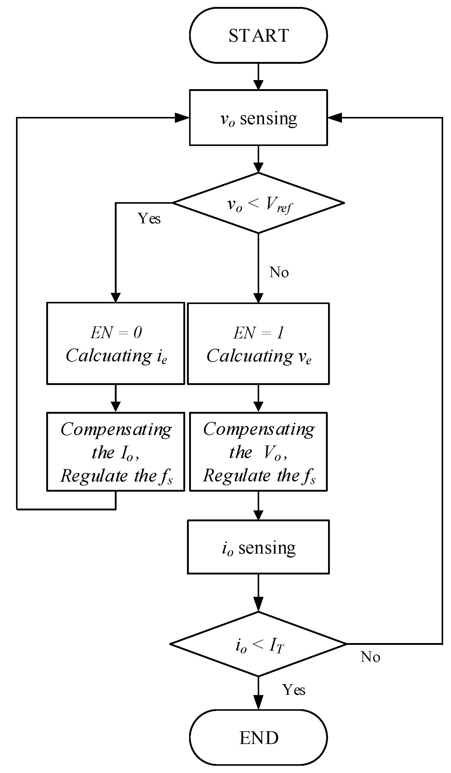
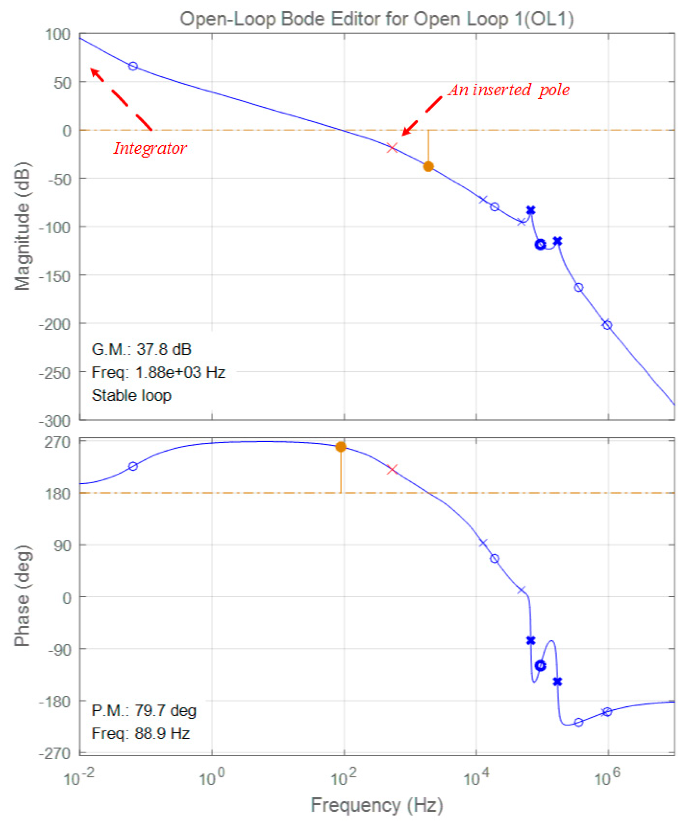
3. Integrated Current-Voltage Compensator

The stable design of the CC and CV compensators requires two small signal transfer functions of the LLC resonant converter with the Li-ion battery, i.e., the control-to-output current Gif for the CC compensator and the control-to-output voltage Gvf for the CV compensator. The transfer functions are derived through Equation (67).
[ G v f ( s ) G i f ( s ) ] = C ( S I A ) 1 B + D
The difference between the two transfer functions results from the difference between the first column and the second column of the C matrix of Equation (64). As mentioned earlier, the variables in the matrix are the same except for the constants rc, rc, and rb, and if the parasitic resistances of the battery and the capacitor are assumed to be sufficiently small, the first and second columns of the C matrix are equal. Consequently, the conventional voltage and current compensator can be incorporated into a single and integrated current-voltage compensator, which helps to eliminate the transient response due to no mode change of the separated CC-CV compensators and to reduce the complexity of the compensator design process. The proposed integrated current-voltage compensator is shown in Figure 7.
Figure 8 shows the operation principle of the proposed integrated current-voltage compensator in the form of a flowchart. When the charging process starts, the integrated current-voltage compensator detects the battery voltage vo. If vo is lower than the voltage reference of CV mode Vref, the enable signal EN becomes 0 and the current error ie, the difference between the output current io and the current reference of CC mode Iref, is fed to the integrated compensator. Consequently, the integrated compensator generates the switching frequency, fs, to regulate the output current io with respect to the current reference of the CC mode Iref. When vo is same as Vref or higher, in contrast, EN becomes 1 and the voltage error ve, the difference between vo and the Vref, is fed to achieve the CV.
CV mode operation. The integrated compensator, in this case, operates to maintain vo with Vref by reducing io. When io is lower than the pre-defined cutoff current, IT, the whole charging process is finished.

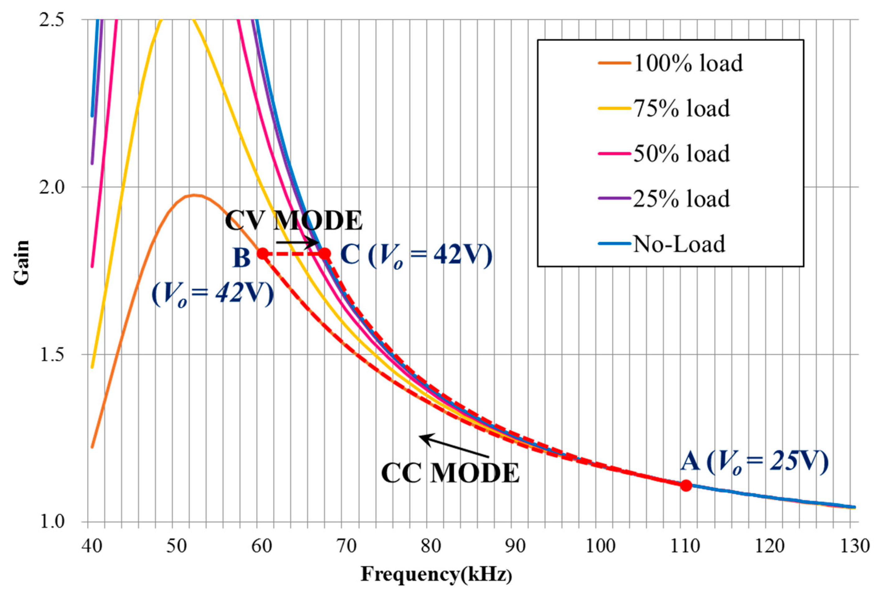
4. Compensator Design Example

Table 1 shows the circuit parameters of the target LLC resonant battery charger. The Iref at the CC mode is set to 7 A and Vref at the CV mode to 42 V. The whole circuit parameters were designed based on the Li-ion battery pack configured with ten series-connected with four paralleled cells as mentioned before. The crossover frequency of the compensator designed in this example was selected near 100 Hz.
The first step in the design of the compensator is to select the operating point for large signal modeling. The operating point selection is obtained using the voltage gain curve derived from fundamental harmonic approximation (FHA) as presented in Ref. [5,26] and the charge profile. Figure 9 shows the voltage gain curve of the LLC resonant converter and operation trajectory obtained by using FHA.
When charging starts, the converter operates in the CC charging mode and changes the switching frequency from point A (110 kHz) to point B (60 kHz) with an output voltage of 42 V. After the voltage of the battery pack reaches 42 V, the converter operates in the CV charging mode and changes the switching frequency from point B to point C (67 kHz), and eventually, the charging process ends. During the charging process, the charging voltage or the charging current varies according to the SOC of the battery, so that the converter operates in the region surrounded by the initial frequency 110 kHz, the output voltage 42 V, and the no-load line. Therefore, the design of the compensator is based on the selection of the worst point of the design in this operating area. In previous research [15], it is reported that the worst equilibrium condition is determined at the intersection of the CC mode and CV mode. Likewise, in this paper, as shown in Figure 10, since the board diagram of point B has the major pole at the lowest frequency, the same point is selected as the design worst condition. At this point, the output voltage is 42 V and the output current is 7 A.
Based on the worst equilibrium condition of case B, the integrated compensator is designed. To achieve zero steady state error, the integrator is added, and then a single pole is added in order to attenuate the high frequency resonant. Finally, the constant gain is tuned to get a proper crossover frequency with sufficient phase margin. In this example, the crossover frequency is set to approximately 100 Hz and the phase margin is approximately 90 degrees. Equation (68) shows the resultant design of the integrated compensator. Figure 11 shows the loop gains with the designed compensator at the worst equilibrium condition of the case. As seen from Figure 11, the crossover frequency is observed at 88.9 Hz and phase margin of 79.7 degrees, which is well matched to the expectation.
C v c ( s ) = 1.4728 × 10 8 1 s ( 1 + 0.000032 s )

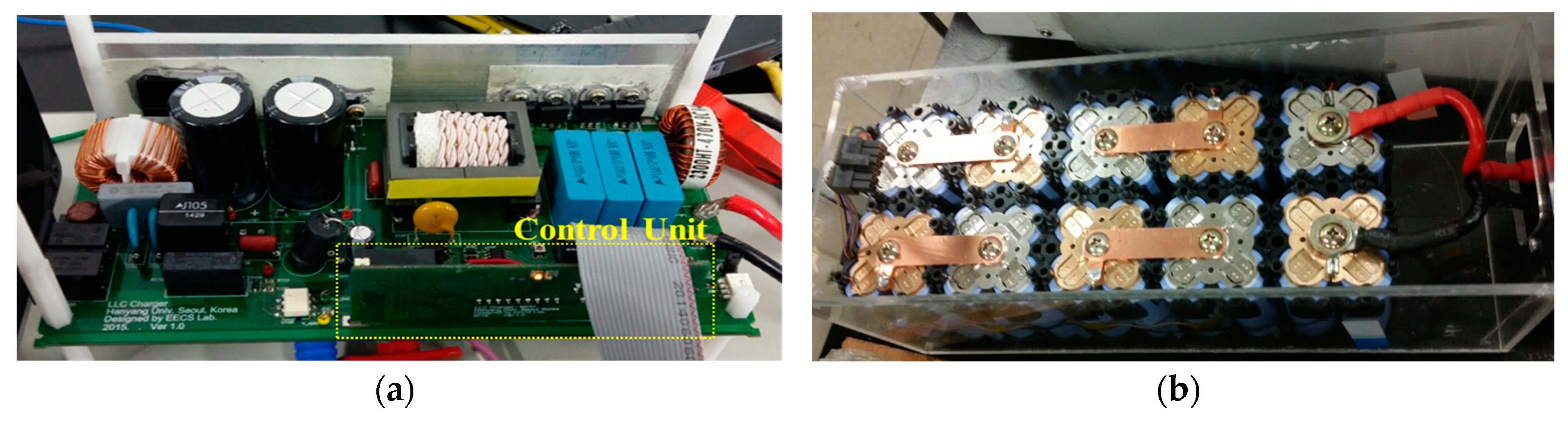
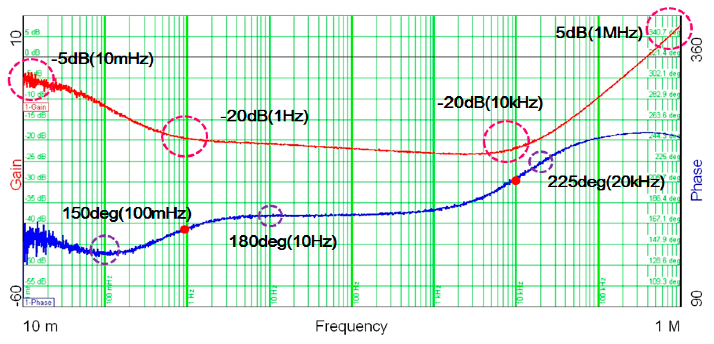
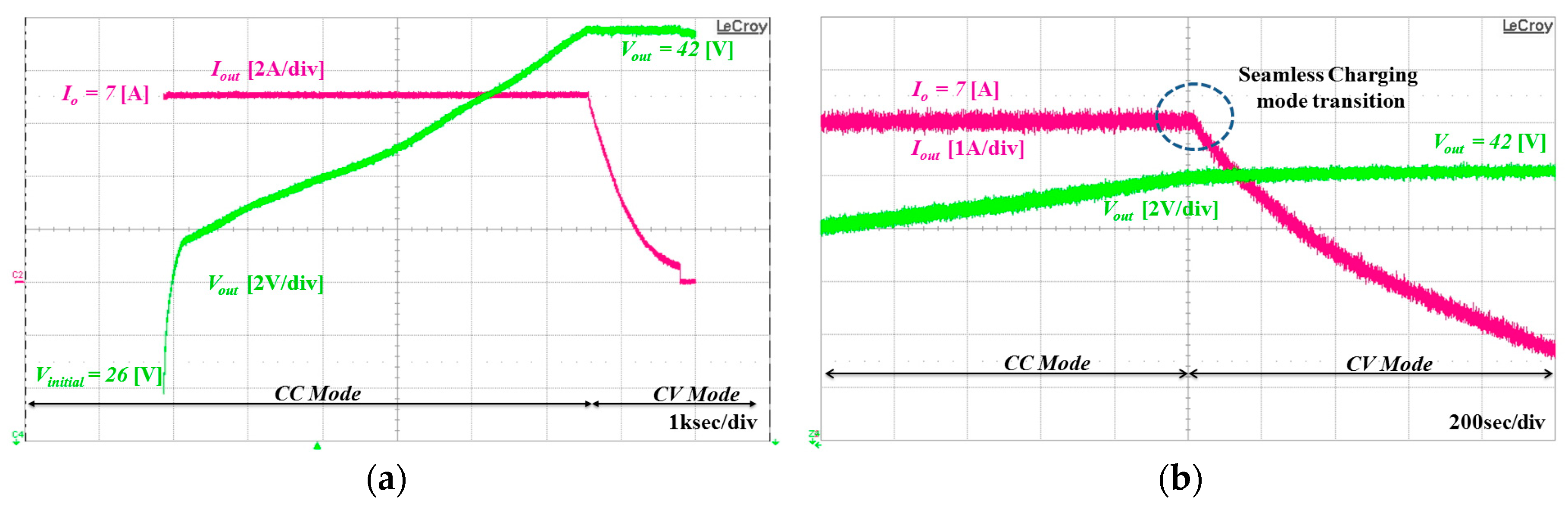
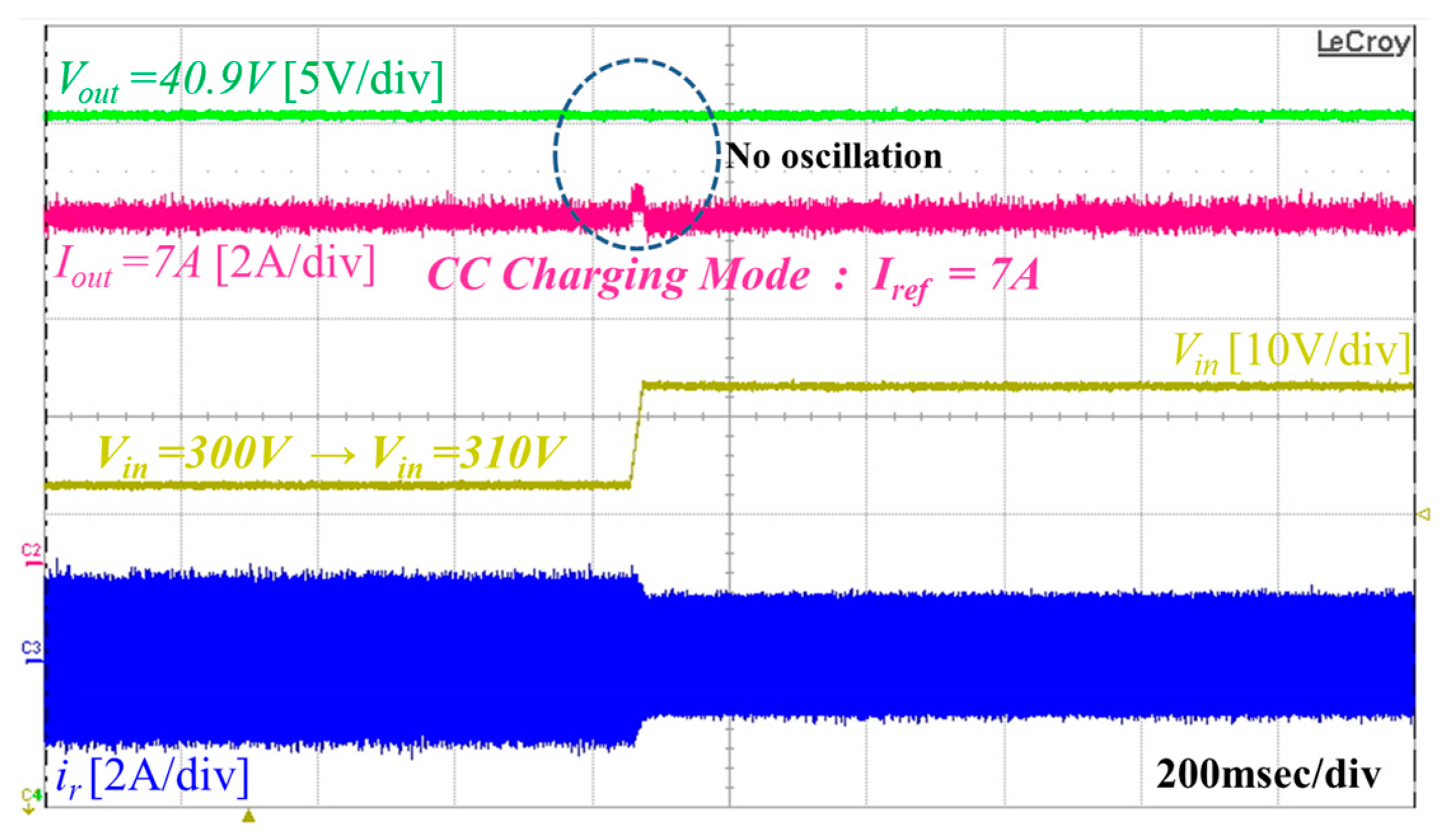
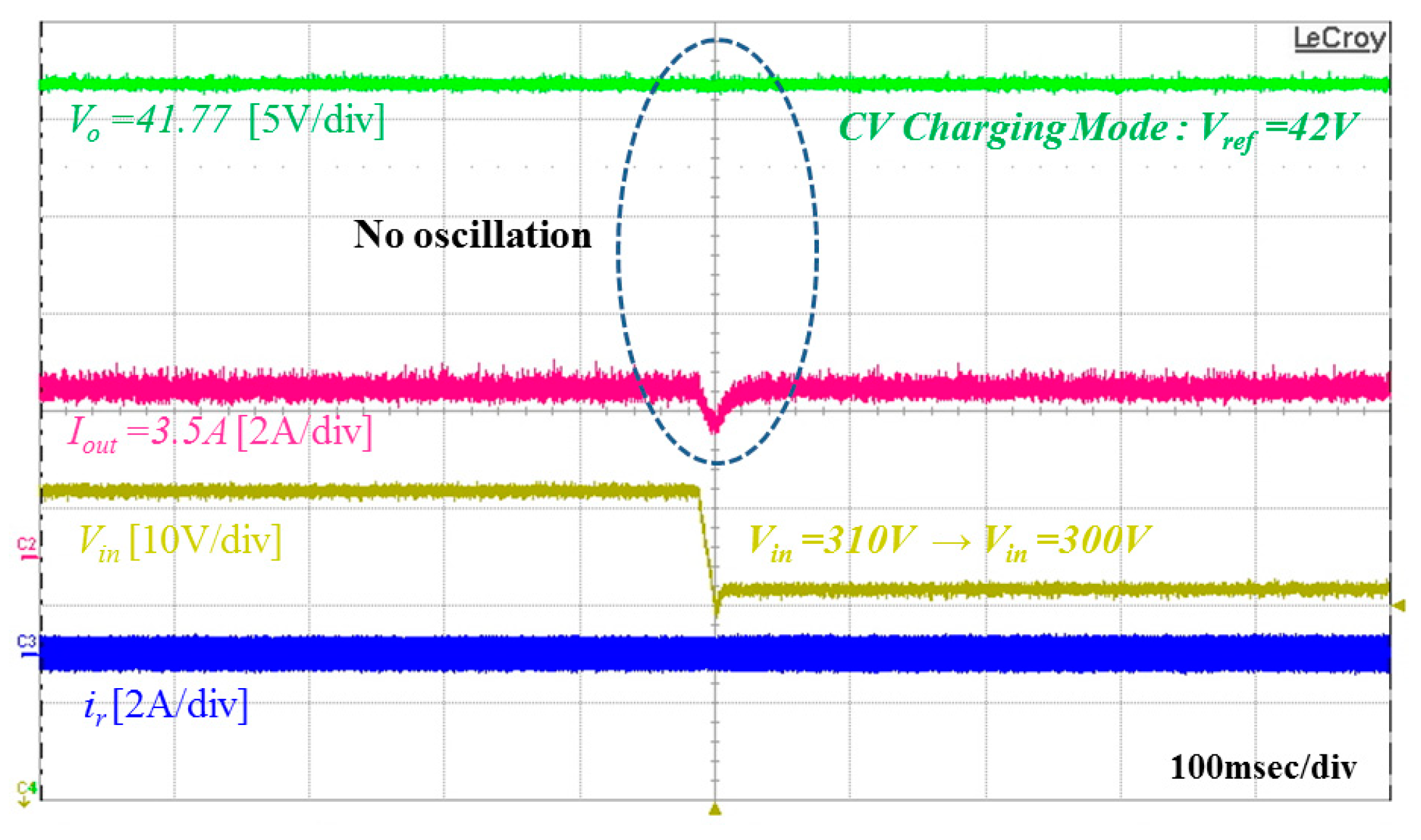
5. Experimental Results

To verify the effectiveness of the proposed compensator, experiments were conducted with a 300 W LLC resonant converter-based battery charger and a Li-ion battery pack, as shown in Figure 12. In the experiment, FSFR2100 (ON semiconductor, Phoenix, AZ, USA) was used for the switching IC and Cortex-M3 (ARM, Cambridge, UK) is used as the digital signal processor (DSP). Detailed circuit parameters are shown in Table 1 of the design example. When the compensation operation is performed, the DSP takes charge of the operation of the proposed compensator and the generation of the output frequency reference, and converts the switching frequency into the voltage value to vary the switching frequency of the switching IC.
Figure 13 shows the experimental result during the overall CC-CV charging process by the proposed integrated current-voltage compensator. The charge process starts at the cut-off voltage of 25 V under the constant-current mode. It can be easily seen that the output current is regulated constantly without any oscillation under the widely varied voltage range.
Figure 13a,b shows the experimental waveform during the CC-CV charging and the magnified waveform during the mode change of the CC-CV mode, respectively, when the proposed compensator is applied. Charging proceeded from a cutoff voltage of the battery pack of 25 V to a full charge voltage of 42 V.
As can be seen from the experimental waveform, the proposed compensator maintains the output current constant without oscillation or transient response during the CC charging mode with wide output voltage range variation, and the output voltage is controlled stably and constantly during the CV charging mode. In addition, CC-CV mode conversion without transient response is achieved.
Figure 14 and Figure 15 show experimental results to confirm the transient response of the compensator during the constant CC charging mode and CV charging mode. As shown in Figure 14, the proposed integrated compensator follows the current reference 7 A well during the CC charging mode without output current fluctuation even under the input voltage variation. The output voltage is also maintained stably. In addition, as shown in Figure 15, the proposed compensator stably follows the output voltage reference during the CV charging mode without oscillation and does not cause charging current oscillation, even when the input voltage is varied from 310 V to 300 V.

6. Conclusions

In this paper, an integrated current-voltage compensator for a battery charger based on the LLC resonant converter and the design procedure is presented. Unlike the conventional CC and CV charging method, the proposed integrated compensator replaces the two separate conventional CC and CV compensators with a single unified compensator. As a result, the compensator design is more intuitive and seamless mode changing is achieved. The proposed compensator is designed through frequency domain analysis, approximation of the Li-ion battery pack, and modeling of the battery charger using FHA and EDF. The proposed compensator performs charging without oscillation or a transient response during the entire charging period and guarantees robust operation even under input voltage variation. In addition, since the proposed compensator performs CC and CV charging by using a single compensator, it is possible to eliminate the transient state under the charging mode conversion and simplify the design process. The proposed method is validated by using a 300 W LLC resonant converter and a Li-ion battery pack. The proposed method does not require additional circuits and simplifies the compensator design process, meaning it can be applied to various applications using CC-CV charging for batteries, from portable devices to E-transportations such as E-bikes or E-scooters.

Author Contributions

Conceptualization, Y.-J.C. and R.-Y.K.; Formal analysis, Y.-J.C. and H.-R.C.; Investigation, Y.-J.C. and R.-Y.K.; Methodology, Y.-J.C.; Project administration, R.-Y.K.; Supervision, S.-M.J.; Validation, Y.-J.C. and H.-R.C.; Writing—original draft, Y.-J.C.; Writing—review & editing, H.-R.C., S.-M.J. and R.-Y.K.

Funding

This research was supported by the Korea Institute of Energy Technology Evaluation and Planning (KETEP) and the Ministry of Trade, Industry & Energy (MOTIE) of the Republic of Korea (No. 20171210201100, No. 20164010200860).

Conflicts of Interest

The authors declare no conflict of interest.

References

  1. Horiba, T.; Maeshima, T.; Matsumura, T.; Koseki, M.; Arai, J.; Muranaka, Y. Applications of high power density lithium ion batteries. IEEE Trans. J. Power Sources 2005, 146, 107–110. [Google Scholar] [CrossRef]
  2. Liu, Y.-H.; Teng, J.-H.; Lin, Y.-C. Search for an optimal rapid charging pattern for lithium-ion batteries using ant colony system algorithm. IEEE Trans. Ind. Electron. 2005, 52, 1328–1336. [Google Scholar] [CrossRef]
  3. Bo, Y.; Lee, F.C.; Zhang, A.J.; Guisong, H. LLC Resonant Converter for Front End DC/DC Conversion. In Proceedings of the APEC 2002, Dallas, TX, USA, 10–14 March 2002; Volume 2, pp. 1108–1112. [Google Scholar]
  4. Yang, B. Topology Investigation for Front End DC/DC Power Conversion for Distributed Power System. Ph.D. Thesis, Virginia Polytechnic Institute and State University, Blacksburg, VA, USA, 2003. [Google Scholar]
  5. Choi, H. Analysis and Design of LLC Resonant Converter with Integrated Transformer. In Proceedings of the APEC 2007, Anaheim, CA, USA, 25 February–1 March 2007; pp. 1630–1635. [Google Scholar]
  6. Spiazzi, G.; Buso, S. Effect of a Split Transformer Leakage Inductance in the LLC Converter with Integrated Magnetics. In Proceedings of the COBEP 2013, Gramado, Brazil, 27–31 October 2013; pp. 135–140. [Google Scholar]
  7. Liu, Y.H.; Luo, Y.F. Search for an optimal rapid-charging pattern for li-ion batteries using the taguchi approach. IEEE Trans. Ind. Electron. 2010, 57, 3963–3971. [Google Scholar] [CrossRef]
  8. Ali, M.U.; Nengroo, S.H.; Khan, M.A.; Zeb, K.; Kamran, M.A.; Kim, H.-J. A Real-Time Simulink Interfaced Fast-Charging Methodology of Lithium-Ion Batteries under Temperature Feedback with Fuzzy Logic Control. Energies 2018, 11, 1122. [Google Scholar]
  9. Wang, S.; Liu, Y. A PSO-Based Fuzzy-Controlled Searching for the Optimal Charge Pattern of Li-Ion Batteries. IEEE Trans. Ind. Electron. 2015, 62, 2983–2993. [Google Scholar] [CrossRef]
  10. Wu, X.; Shi, W.; Du, J. Multi-Objective Optimal Charging Method for Lithium-Ion Batteries. Energies 2017, 11, 1122. [Google Scholar] [CrossRef]
  11. Chen, L.R. Design of duty-varied voltage pulse charger for improving li-ion battery-charging response. IEEE Trans. Ind. Electron. 2009, 56, 480–487. [Google Scholar] [CrossRef]
  12. Huang, J.W.; Liu, Y.H.; Wang, S.C.; Yang, Z.Z. Fuzzy-Control-Based Five-Step Li-Ion Battery Charger. In Proceedings of the PEDS 2009, Taipei, Taiwan, 2–5 November 2009; pp. 1547–1551. [Google Scholar]
  13. Hussein, A.A.-H.; Batarseh, I. A review of charging algorithms for nickel and lithium battery chargers. IEEE Trans. Veh. Technol. 2011, 60, 830–838. [Google Scholar] [CrossRef]
  14. Hoque, M.M.; Hannan, M.A.; Mohamed, A. Optimal CC-CV Charging of Lithium-Ion Battery for Charge Equalization Controller. In Proceedings of the ICAEES 2016, Putrajaya, Malaysia, 14–16 November 2016; pp. 610–615. [Google Scholar]
  15. Dow, Y.S.; Son, H.I.; Lee, H.D. A Study on Half Bridge LLC Resonant Converter for Battery Charger on Board. In Proceedings of the IEEE 8th International Conference on Power Electronics and ECCE Asia (ICPE & ECCE) 2011, Jeju, Korea, 30 May–3 June 2011; pp. 2694–2698. [Google Scholar]
  16. Deng, J.; Li, S.; Hu, S.; Mi, C.C.; Ma, R. Design methodology of LLC resonant converters for electric vehicle battery chargers. IEEE Trans. Veh. Technol. 2014, 63, 1581–1592. [Google Scholar] [CrossRef]
  17. Musavi, F.; Craciun, M.; Gautam, D.S.; Eberle, W.; Dunford, W.G. An LLC resonant DC-DC converter for wide output voltage range battery charging applications. IEEE Trans. Power Electron. 2013, 28, 5437–5445. [Google Scholar] [CrossRef]
  18. Choi, Y.J.; Han, H.G.; Choi, S.Y.; Kim, S.I.; Kim, R.Y. A high efficiency LLC resonant converter-based Li-ion battery charger with adaptive turn ratio variable scheme. Trans. KIEE J. Electr. Eng. Technol. 2018, 13, 124–132. [Google Scholar]
  19. Park, K.H.; Choi, Y.J.; Choi, S.Y.; Kim, R.Y. Design Consideration of CC-CV Controller of LLC Resonant Converter for Li-Ion Battery Charger. In Proceedings of the IFEEC 2015, Taipei, Taiwan, 1–4 November 2015; pp. 1–6. [Google Scholar]
  20. Jang, J.; Joung, M.; Choi, B.; Hong, S.; Lee, S. Dynamic analysis and control design of optocoupler-isolated LLC series resonant converters with wide input and load variations. IET Trans. Power Electron. 2012, 5, 755–764. [Google Scholar] [CrossRef]
  21. Jang, J.; Joung, M.; Choi, S.; Choi, Y.; Choi, B. Current Mode Control for LLC Series Resonant dc-to-dc Converters. In Proceedings of the APEC 2011, Fort Worth, TX, USA, 6–11 March 2011; pp. 21–27. [Google Scholar]
  22. Jang, J.; Joung, M.; Choi, B.; Kim, H.G. Dynamic Analysis and Control Design of Optocoupler-Isolated LLC Series Resonant Converters with Wide Input and Load Variations. In Proceedings of the ECCE 2009, San Jose, CA, USA, 20–24 September 2009; pp. 758–765. [Google Scholar]
  23. Choi, Y.J.; Choi, S.Y.; Kim, R.Y. An Integrated Voltage-current Compensator of LLC Resonant Converter for Li-ion Battery Charger Applications. In Proceedings of the IPEMC-ECCE Asia 2016, Hefei, China, 22–26 May 2016; pp. 3783–3790. [Google Scholar]
  24. Yang, S.H.; Liu, J.W.; Wang, C.C. A single-chip 60-V bulk charger for series Li-ion batteries with smooth charge-mode transition. IEEE Trans. Circuits Syst. I Regul. Pap. 2012, 59, 1588–1597. [Google Scholar] [CrossRef]
  25. Chen, M.; Rincon-Mora, G.A. Accurate, compact, and power-efficient Li-ion battery charger circuit. IEEE Trans. Circuits Syst. II Express Briefs 2006, 53, 1180–1184. [Google Scholar] [CrossRef]
  26. FairChild. AN-4151: Half-Bridge LLC Resonant Converter Design Using FSFR-Series Fairchild Power Switch; FairChild: Sunnyvale, CA, USA, 2014. [Google Scholar]
  27. Chang, C.H.; Chang, E.C.; Cheng, C.A.; Cheng, H.L.; Lin, S.C. Small Signal Modeling of LLC Resonant Converters Based on Extended Describing Function. In Proceedings of the 2012 International Symposium on Computer, Consumer and Control (IS3C), Taichung, Taiwan, 4–6 June 2012; pp. 365–368. [Google Scholar]
  28. Yang, E.X.; Lee, F.C.; Jovanovic, M.M. Small-Signal Modeling of Series and Parallel Resonant Converters. In Proceedings of the APEC 1992, Boston, MA, USA, 23–27 February 1992; pp. 785–792. [Google Scholar]
  29. Microchips. AN1477: Digital Compensator Design for LLC Resonant Converter; Microchips: Chandler, AZ, USA, 2012. [Google Scholar]
  30. Yang, E.X.Q. Extended Describing Function Method For Small-Signal Modeling of Resonant and Multi-Resonant Converters. Ph.D. Thesis, Virginia Polytechnic Institute and State University, Blacksburg, VA, USA, February 2014. [Google Scholar]
Figure 1. The battery charger including the conventional separated compensators.
Energies 11 01325 g001
Figure 2. Measurement results of the frequency response of the battery pack at the nominal voltage.
Energies 11 01325 g002
Figure 3. Frequency response approximation result of the battery pack at the nominal voltage.
Energies 11 01325 g003
Figure 4. Equivalent circuit of the LLC resonant converter.
Energies 11 01325 g004
Figure 5. Large signal model of the LLC resonant converter.
Energies 11 01325 g005
Figure 6. Small signal model of LLC resonant converter.
Energies 11 01325 g006
Figure 7. A battery charger including the proposed integrated current-voltage compensator.
Energies 11 01325 g007
Figure 8. Operation principle of proposed compensator.
Energies 11 01325 g008
Figure 9. The operation trajectory of the entire charging process.
Energies 11 01325 g009
Figure 10. Magnitude and phase plot of the control-to-output transfer function.
Energies 11 01325 g010
Figure 11. Magnitude and phase plot of loop gains with the designed compensator.
Energies 11 01325 g011
Figure 12. Experimental setup: (a) LLC resonant battery charger, (b) Li-ion battery pack.
Energies 11 01325 g012
Figure 13. Experiment waveform during the CC-CV charging process: (a) during the whole charging period, (b) magnified waveform under the mode change.
Energies 11 01325 g013
Figure 14. Experimental waveform of the proposed compensator with the CC mode under step-change of the input voltage.
Energies 11 01325 g014
Figure 15. Experimental waveform of the proposed compensator with CV mode under step-change of the input voltage.
Energies 11 01325 g015
Table 1. Circuit parameters of the LLC resonant battery charger.
DesignatorValue (Unit)
Nominal Input Voltage (Vin)310 (V)
Resonant Frequency (fo)110 (kHz)
Output Voltage Range (Vout)25–42 (V)
Transformer Turn Ratio (n)6.5
Quality Factor (Q)0.25
Magnetizing Inductance (Lm)391 (uH)
Resonant Inductor (Lr)78 (uH)
Resonant Capacitor (Cr)27 (nF)
Output Capacitor (C)30 (uF)
ESR of Resonant Current Path (rs)500 (mΩ)
ESR of Output Capacitor (rc)15 (mΩ)

