A New Diagnostic Algorithm for Multiple IGBTs Open Circuit Faults by the Phase Currents for Power Inverter in Electric Vehicles


1
Laboratory of Low Emission Vehicle, Beijing Institute of Technology, Beijing 100081, China
2
National Lab of Auto Performance and Emission Test, Beijing Institute of Technology, Beijing 100081, China
*
Author to whom correspondence should be addressed.
Energies 2018, 11(6), 1508; https://doi.org/10.3390/en11061508
Submission received: 27 April 2018
/
Revised: 5 June 2018
/
Accepted: 8 June 2018
/
Published: 10 June 2018
(This article belongs to the Special Issue Emerging Power Electronics Technologies for Power Systems and Machine Drives)
Abstract
:In order to simplify the application and improve diagnostic speed of the diagnostics, a novel method to diagnose multiple open circuit faults in insulated gate bipolar transistors (IGBTs) by three-phase currents for power inverter in electric vehicles is presented. The summation of currents with semi-period phase-difference is described in diagnostic variables with exploration of the current information in faulty condition. In contrast with plentiful existing methods which rely on the motor models and control parameters, this algorithm merely requires phase currents. Meanwhile, the normalized way based on the absolute phase currents and variable parameter moving average method are applied to improve the diagnostic speed and independence of load variation, which contributes to the real-time application in the electric vehicles. Experimental results, using a vector-controlled permanent magnet synchronous motor (PMSM) and digital signal processor MC56F8346, are presented to verify the algorithm effectiveness, showing many features, such as applicability for multiple open circuit faults, well-robustness against false alarms, briefness and agility for the diagnosis function.
1. Introduction
With the advent of worldwide shortage of energy sources, global warming and the more stringent emission regulations, electric vehicles have played a significant role for the society [1,2,3,4]. The popularity of electric vehicles makes electrical machines more widely used and the corresponding drive systems are receiving more and more attention in the field [5,6]. Although, the current drive systems have already achieved a high level of maturity, they are still inclined to undergo several unpredictable failures due to the complicated structure and exposure to high stress environments [7]. In order to decrease the expense and develop the reliability of the drive systems, the corresponding fault diagnostic algorithms have been the research hotspots during the last decade [8,9,10]. Furthermore, fault diagnosis is the foundation of the follow-up fault-tolerant control, which has great significance to the safety and operation reliability of electric vehicles.
In general, the common vulnerable components in the drive systems are capacitors, the corresponding gate drive circuits and semiconductor power switches where the last ones represent mostly over 31% scoring average [11]. Furthermore, short circuit faults and open circuit faults of insulated gate bipolar transistors (IGBTs) are the most common faults in the power switches [12,13], but the former ones are fatal due to the transient overcurrent which is able to damage IGBTs in less than 10 . Therefore, short circuit faults have to be detected by hardware circuits. In contrast, open circuit faults cannot cause an immediate shutdown of the drive system; however, if they are not detected as quick as possible, they may cause another secondary devastation for the total drive systems. Thus, it shows great significance to identify and detect the faulty switches as fast as possible.
Generally, according to the diagnostic signals, voltage-type and current-type diagnostic algorithms are the universal applications. Due to the fast response of voltage signal, the less diagnostic time can be guaranteed with voltage-type algorithms [14]. However, such algorithms usually require extra sensors and hardware circuits to identify the voltage signals, which increases the cost and complexity of drive systems. Although, paper [15] has proposed one novel voltage-based approach without any extra device, the voltage observer based on motor model and parameters is indispensable in the diagnostic system. Accordingly, current exiting voltage-type algorithms make the diagnostic process difficult to realize and they are seldom applied into electric vehicles. Current-type diagnostic algorithms are able to detect the open circuit faults without any extra device. Notwithstanding, current signals have the hysteresis effect, which can cause a little time delay. So it is quite essential to improve the diagnostic speed for the current-type diagnostic approaches [16]. Therefore, currently fast-acting current-type diagnostic algorithms have realized universal application in electric vehicles because of their lower expense and high reliability.
In the previous researches, current-type diagnostic algorithms based on the average current Park’s vector are presented in paper [17,18,19,20]. The approaches in paper [17,18] calculate the current vector’s midpoint position or the Park’s vector slope and identify the fault switches by finding out the incomplete trajectory and phase-angle information. However, these approaches have several drawbacks mainly related to the load variation. In order to overcome these above defects, the normalized DC current method is proposed in paper [19], however, this method is not available in the closed-loop systems. So the modified normalized DC current method is developed in paper [20]. Especially, the similar method further combined with fuzzy logic way in paper [21] is addressed and has presented many advantages in the process of the complicated load conditions. However, the algorithms based on modified normalized DC current method in [20] expresses hysteresis effect and the fuzzy logic way in [21] requires more complex recognized processes, which is a challenge for the general processors.
Recently, many effective current-type methods based on the direct analysis of current waveforms have gained more attention [22,23,24,25]. An effective open circuit fault diagnosis based on the operative characteristics of the brushless direct motor is shown in [22], which is realized by observing the performance of phase current and other parameters about motors or inverters. Similarly, practical current-based diagnostic algorithms by identifying the reference current errors and average absolute value of currents respectively are addressed in [23,24], and in order to improve the diagnostic speed, a fast-acting approach based on the amplitude of the d-q axis referential currents is proposed in [25]. These above methods have the ability to simply the calculation and further optimize diagnostic speed. However, the referential currents and electric angular signal merely exist in the initial controllers, which means that they cannot be applied into the outside independent diagnostic devices or non-closed-loop system where the referential signals cannot be obtained. There is one open-transistor fault diagnostics by analyzing the load current in paper [20] and this method is an extension of the normalized dc-components method and has some advantages in robustness against the false alarms. However, this method has some drawbacks such as higher complexity and larger detection times.
Nowadays, with the development of modern control theory, some intelligent algorithms, such as, fuzzy logic approach [26], sliding mode observer based on switching model approach [27], knowledge-based model approach [28], adaptive network-based fuzzy inference approach [29], wavelet transform and neural network algorithm [30], are applied into the diagnosis for open circuit faults in voltage source inverters. These approaches have many advantages in the diagnostic speed and stable capacity. However, due to complicated calculation and the unattainable recognition of motor’s parameters, they require high-performance processors and show poor universality. Therefore, intelligent algorithms still stay at a level of simulation and present little applications in electric vehicles.
The literature review presents that although various existing diagnostic algorithms concern about open circuit faults, they have less considered the follow three aspects: practical application in electric vehicles, conciseness in the implemented process and the well-robustness against false alarms. In this paper, a novel diagnostic algorithm for multiple IGBTs open circuit faults is proposed and this algorithm has many features, such as the effectiveness for single and multiple open circuit faults, eminent diagnostic speed, no need of extra sensors and inner referential signals, independence of varied load condition, robustness against false alarms, especially showing great contribution to the outside fault diagnostic devices and the application in electric vehicles. Aiming at these advantages, the algorithm and its relevant experiments are designed in the follow-up sections.
The primary approach is to obtain and analyze phase current information under normal and faulty conditions. The summation of currents with semi-period phase-difference is non-zero under faulty condition, which could be the principle to localize the faulty switches. In order to improve the diagnostic speed and enhance the robustness against false alarms by load level, the normalized method and the variable parameter moving average method are adopted. The new algorithm is implemented with a digital signal processor MC56F8346 (NXP Semiconductors, Eindhoven, Netherlands) and verified experimentally with the internally designed inverter system. Experimental results manifest that this algorithm has great advantage in the detect speed and resistivity against false alarms, proving its advanced diagnostic level.
2. Performance of Open Circuit Fault
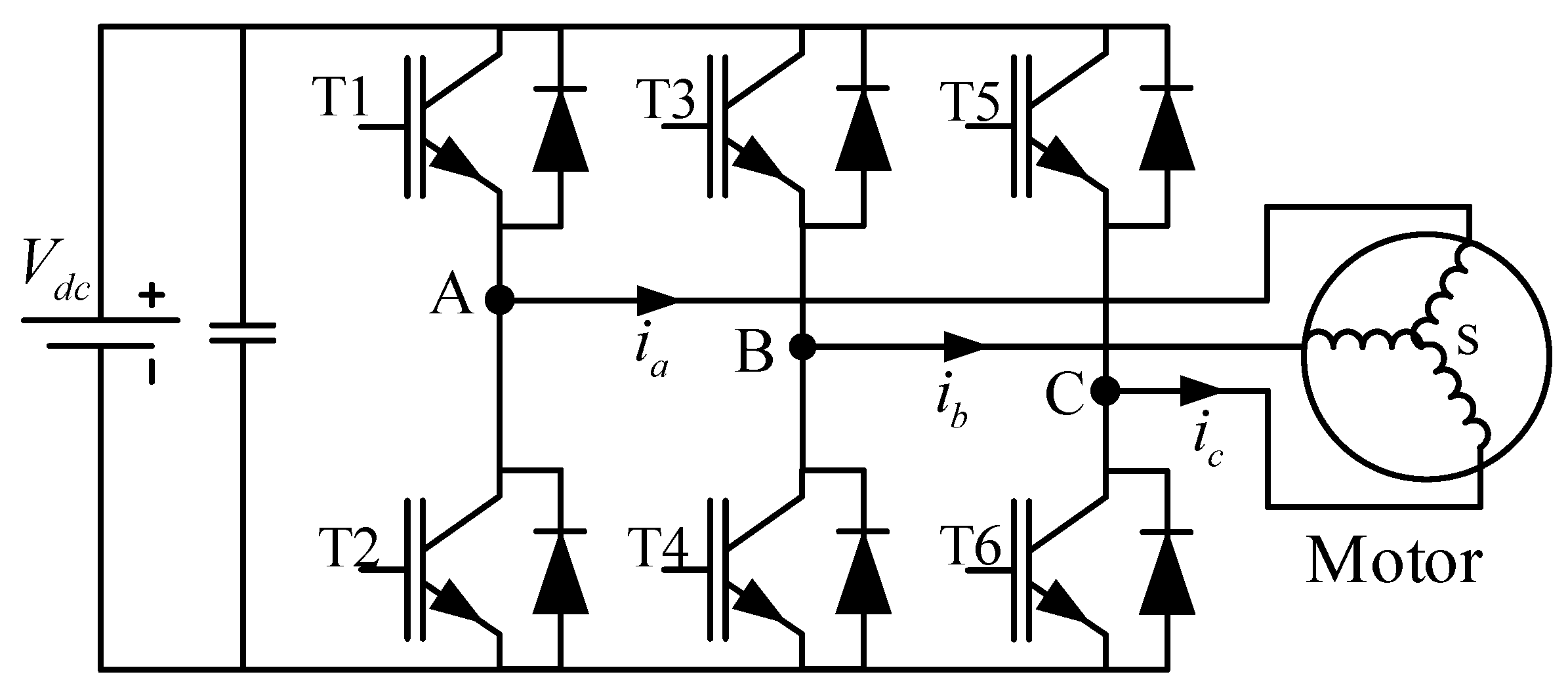
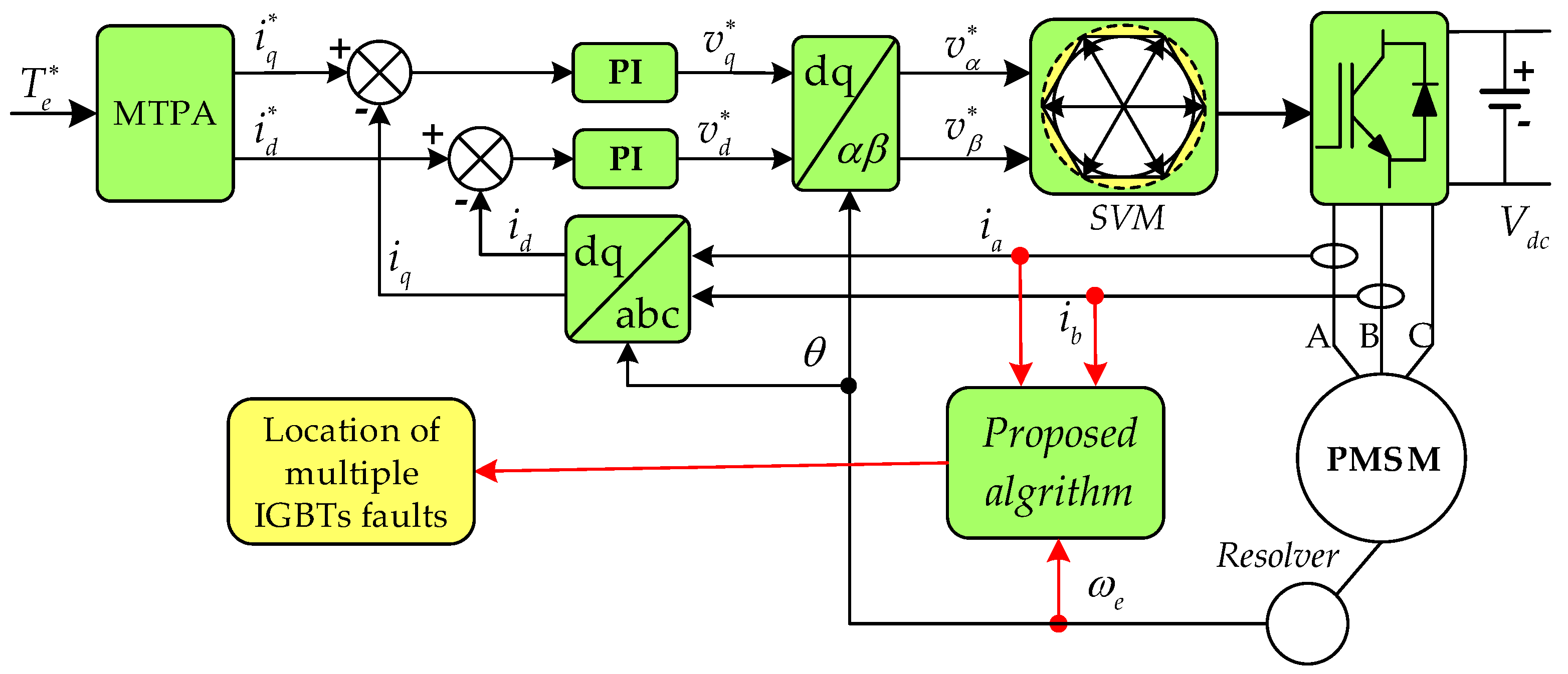
This section concerns about the performance of phase-current under open circuit fault condition. The topological structure of the drive system is shown in Figure 1, where the corresponding power switches are named as T1–T6.
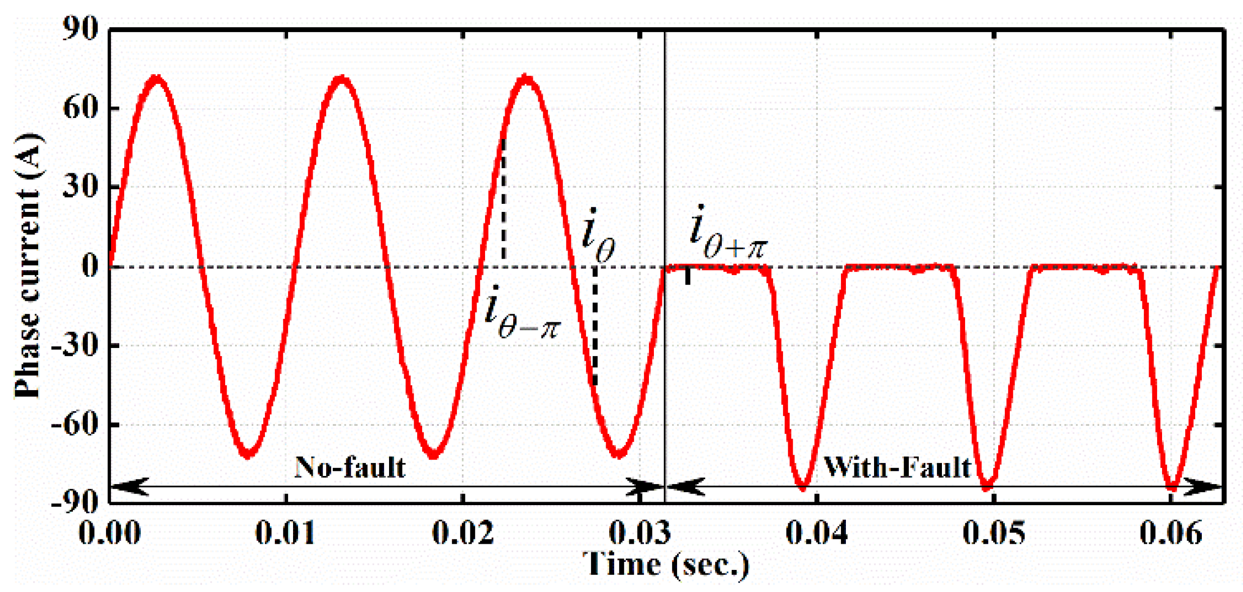
Under the condition 360 rpm/30 Nm, the current waveform of phase A with the occurrence of single fault in switch T1 is shown in Figure 2. Under normal condition, due to the well-operative current regulator, three-phase currents perform completely as sinusoidal way, which means the output torque is stable.
At t = 0.032 s, an open circuit fault in power switch T1 is introduced, which causes that phase A cannot produce positive current and the torque can be fluctuant. Meanwhile, the summation of currents with semi-periodic phase-difference is non-zero; for example, in faulty condition, while it is in normal condition. From this view of summation, the diagnostic variable can be designed as zero or non-zero corresponding with the faulty and normal conditions.
3. Open Circuit Fault Diagnostic Algorithm by Phase Current
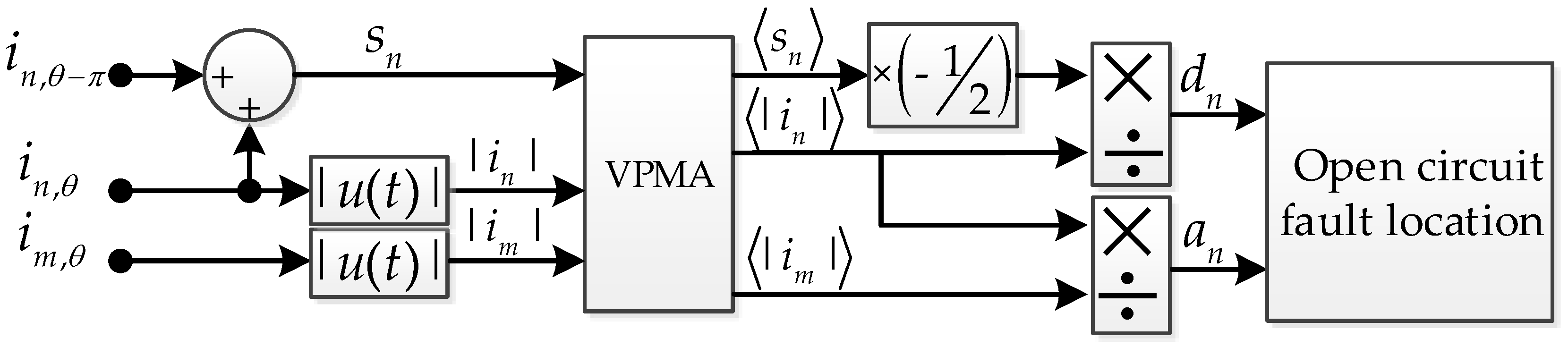
The diagram of proposed algorithm is illustrated in Figure 3. The phase-current required in this algorithm can be obtained from current sensors. The variable parameter moving average method is utilized to routinely deal with operating count for different motor speed condition. The diagnostic variables are obtained by normalizing the periodic summation with the periodic absolute value of phase current . The variables are used to diagnose most multiple open circuit faults except for the phase failure. Therefore, auxiliary diagnostic variable are developed to deal with the faulty condition about phase failure.
The summation of phase currents with semi-periodic phase-difference are calculated from phase current as follows:
where and means the electrical angular. In order to improve the trustworthiness of the diagnosis and reduce computation complexity, the average value of summation over a fundamental current period is applied and expressed as follows:
Furthermore, the value of corresponds to the amplitude of phase currents which refers to electromagnetic torque, so for the sake of being independence of load and decreasing the total calculation workload, the periodic summation is normalized by dividing the periodic absolute value of phase current . As a result, the final diagnostic variable can be expressed as:
where the coefficient is used to ensure that diagnostic variable would always take values within the range of .
From the Equations (1)–(3), it can be shown that the diagnostic variable is realized by some simple mathematical operations and its conciseness contributes to the easier implemented process in digital signal processors and it is useful for the application in electric vehicle since it takes up a little calculation resource in the controller.
Under normal operating conditions, three-phase currents of permanent magnet synchronous motor (PMSM) are sinusoidal waves, and they can be illustrated as follows:
where , and are the maximum amplitude of the phase currents, the electrical angular velocity and the initial phase, respectively. As mentioned earlier, phase current performs as sinusoidal waveform normally, resulting in the values of and are equivalent to zero. Nevertheless, when single open circuit fault occurs in power switch, at least one diagnostic variable will change distinctly. Considering one fault in T1, phase A current during the positive half-cycle is eliminated while it remains well-sinusoidal during the negative half-cycle as shown in Figure 2. Therefore, the equation of phase A in the fundamental current period can be expressed as follows:
In this case, substituting Equation (5) into (2) and (3), can be calculated as
Solving this equation, the final value of diagnostic variable is
Similarly, it is easy to find out that the diagnostic variable is near −1 when the fault in T2 occurs. Consequently, it can be seen that are approximately equivalent to 1 for open circuit fault in the upper leg and −1 for the lower leg. Therefore, the single fault switch can be detected by observing which diagnostic variable firstly crosses the given threshold value based on Table 1.
Considering multiple open circuit faults in different switches, phase current waveforms are seriously distorted, resulting in the diagnostic variables in vain under some specific circumstances. For example, in case of double simultaneous faults in the same phase (named phase failure), the corresponding phase is obstruent and the periodic summation is close to zero, causing the false diagnosis. Therefore, auxiliary diagnostic variables are required for multiple open circuit faults. The auxiliary diagnostic variables in this paper are presented as follows:
where and . Under normal operating conditions, auxiliary diagnostic variables take values as 1 because of the symmetry current waveforms. When the phase fault (exactly the upper and lower legs are faulty in the same phase) occurs, absolute value of is equal to near zero, causing the corresponding auxiliary variable rapid decrement to zero. Consequently, the faulty transistors can be detected by settling the detection threshold . Generally, two diagnostic thresholds and are utilized to judge the occurrence of open circuit faults and the symptom of both diagnostic variables are expressed as follows:
For a typical three-phase voltage source inverter, 27 possible open circuit faults [23] can be diagnosed and localized by utilizing both diagnostic variables according to the principle shown in Table 2. Normally, most open circuit faults can be detected only with diagnostic variables while phase failure must rely on auxiliary diagnostic variables . It should be noted that in some special cases the diagnosis may be ambiguous due to the closed-loop currents. For instance, when multiple open circuit faults in T1 and T3 simultaneously occur, currents in the upper half-bridges are able to flow out only in T5, leading to the blocking of the lower half-bridge in phase C. Therefore, whether T6 is faulty or not, cannot be detected by using this method.
Considering the settling of threshold , it can be proved that diagnostic variables will converge to 1 or −1 under open circuit fault condition. So the threshold should be settled between 0 and 1. A small benefits to diagnostic speed; however, it may increase the possibility of misdiagnosis. For the improvement of diagnostic speed and its trustworthiness, the threshold is selected to be 0.55 based on the subsequent experimental results and for the same reason, the threshold is settle to 0.4. Furthermore, in order to quickly capture open circuit faults, one identified threshold is required and the value of is settled to 0.3. It must be noted that is only used to identify the occurrence of open circuit faults and it cannot localize final faulty power switches. Therefore, if a fast diagnosis is not required primarily, the threshold can be neglected.
The variable parameter moving average method is utilized to improve the diagnostic speed and reduce the computation burden. The periodic average summation is described as the continuous parameter, however, it is inapplicable for discrete digital signal processor. So the discrete periodic average summation is the average value of over an electrical period in the discrete system. Under different motor speeds, the electrical period is variable synchronously, so the periodic average summation can be obtained by using the variable parameter N relevant to the motor speed, and its formula is shown as follows:
where means the average value of summation in discrete system, N is the calculated counts for different speed and , is the calculated period and is the practical value at before .
Considering the feasibility of the average summation periodic average, the main factor is the calculated period. We know that and there are N calculated steps or corresponding N arrays to record the current values in every calculated period. If the is chosen as too little, it means the parameter N would be very big, and it’s a heavy burden on the digital signal processor. In contrast, if the is chosen as too large, the accuracy of calculation cannot be guaranteed. So the can be chosen based on the capacity of the digital signal processor. For example, the is chosen as 0.05 ms in this experiment. And under motor speed 720 rpm condition, and it is acceptable for the experimental digital signal processor.
4. Performance Evaluation Results
Firstly, Matlab/Simulink (Matlab2016b, MathWorks, Natick, MA, USA) model has been developed to verify the effectiveness of proposed algorithm and simulation results are utilized for the analysis and the localization of open circuit faults under all conditions referred in Table 2. In the early design of the algorithm, the simulation has a high significance to show the effectiveness of the method and pave the road to the preparation of subsequent experiments. In addition, the simulation model consists of the DC voltage source subsystem, the motor and drive power electronics subsystem, the space vector control subsystem where the diagnostic algorithm is embedded. The dead time and the voltage drop of the semiconductor are neglected in the simulation. Furthermore, with the target of validating proposed algorithm practically, experimental tests are implemented and thresholds , and have been determined to be equal to 0.3, 0.55 and 0.4, respectively. Due to the similar results in simulations and experiments, only the relevant experimental results are expressed.
4.1. Experimantal Setup
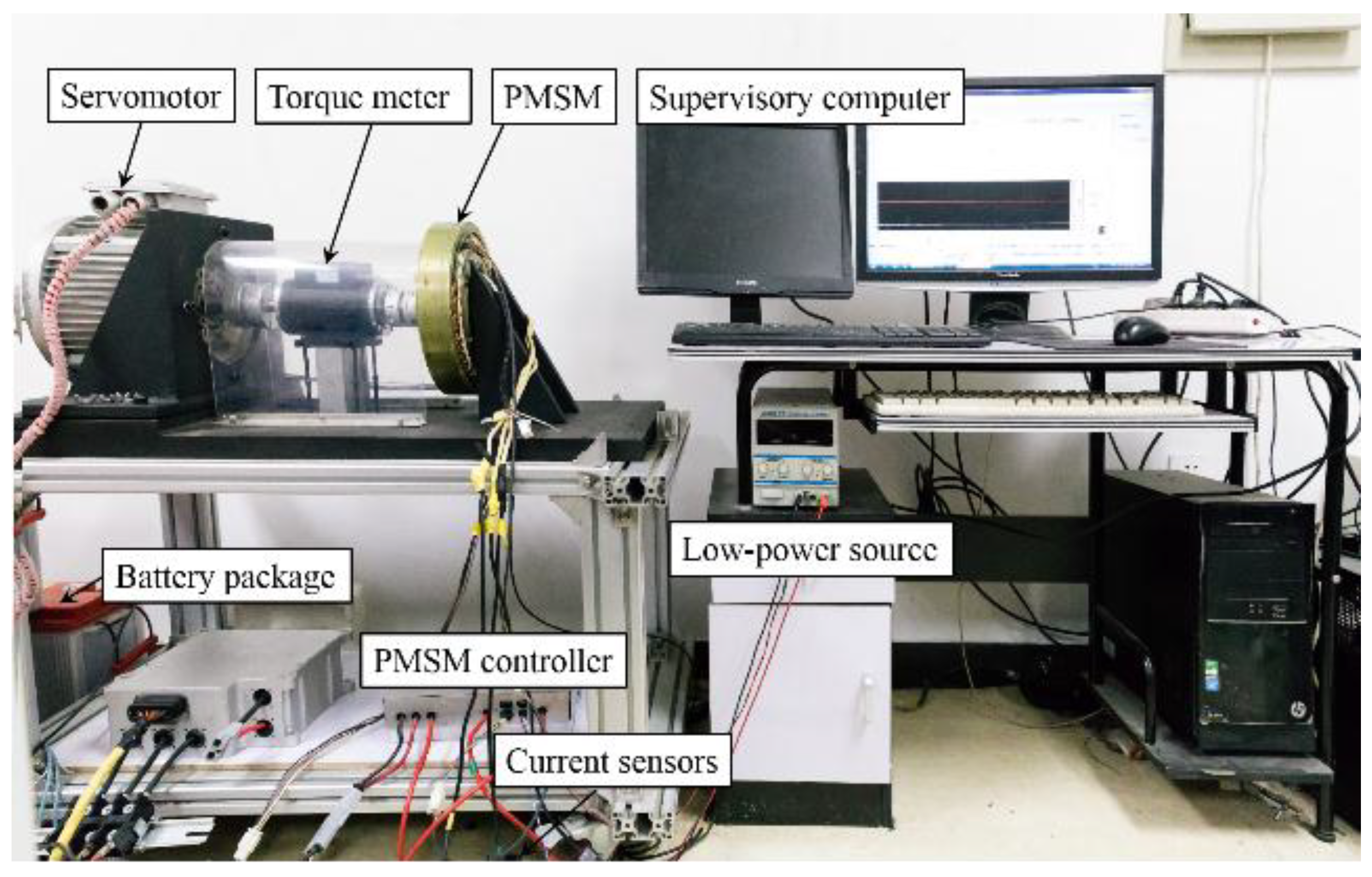
With the purpose of verifying the effectiveness of practical algorithm in the paper, experimental tests are implemented with the test bench shown in Figure 4. The experiment is performed basically utilizing a PMSM coupled to a magnetic-power brake dynamometer that is used to provide the external load. The parameters of 2 kW PMSM are given in Table 3. The other configuration of experimental devices contains a LiFePO4 battery pack, a torque meter and a three-phase inverter system developed internally. A six-leg bridge drive circuit with single IGBTs (AUPS4067D1) (Infineon Technologies, Munich, Germany) constitutes the subject of inverter and digital signal processor (MC56F8346) implements the proposed algorithm when three Allegro current sensors are used to measure stator phase currents.
The block diagram of drive system with proposed open circuit fault diagnostic algorithm in experimental tests is shown in Figure 5. The drive system adopts one novel space vector control approach based on field-oriented strategy [31]. The pulse-width modulation inverter operates with a switching frequency of 10 kHz and PI current regulator’s frequency is 20 kHz. The rotor position and speed signal are obtained with a resolver. For the sake of not destroying existing devices, switches’ open circuit faults are produced by removing relevant gate control signals.
In order to verify the independence between the algorithm and power levels, experiments were conducted under two different mechanical speeds conditions, namely 360 rpm and 720 rpm, respectively. Under both speed conditions, several multiple faults are tested for two load conditions equivalent to 60% and 100% of the motor rated toque. Moreover, in order to evaluate the robustness against false alarms, one load variation condition is practiced experimentally.
4.2. Experimental Results
4.2.1. 720 rpm Operation
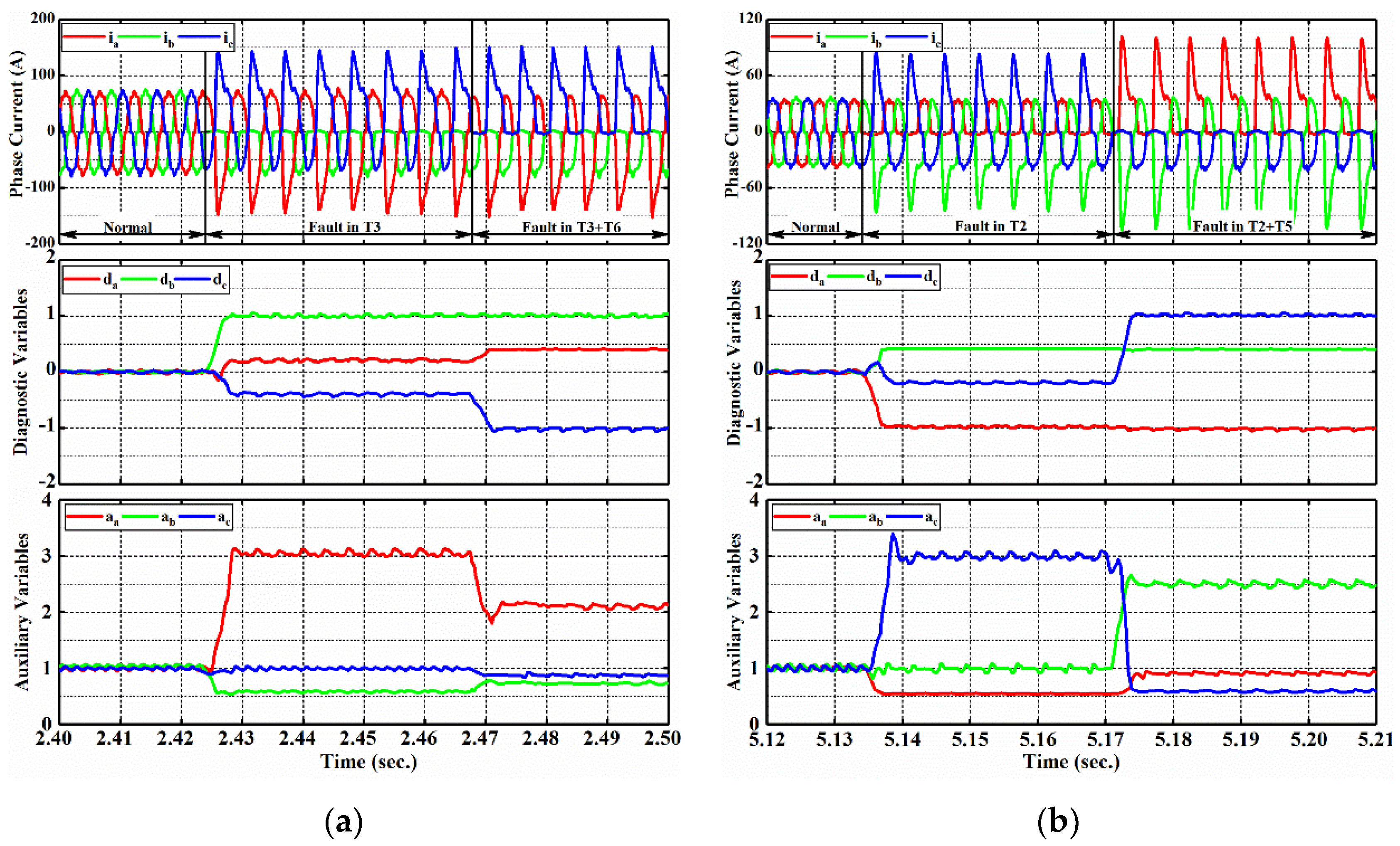
Figure 6a shows experimental results about phase currents, values of diagnostic variables and auxiliary variables when switches T3 and T6 are faulty under 100% of rated torque.
As shown in Figure 6a, under normal condition, three-phase current waveforms are sinusoidal and symmetrical, resulting in diagnostic variables equivalent to zero along with auxiliary variables approximately equivalent to 1. When the first open circuit fault in T3 occurs at t = 2.424 s, phase B current is prevented in the upper half-bridge leg while remaining currents are distorted with the maximum value up to 145 A. Consequently, diagnostic variable increases and exceeds the identified threshold and afterwards detection threshold dramatically, converging to the final value of 1, while the other diagnostic variables reach to near 0.23 and 0.38, respectively. Fast fault identification and localization are realized and they take only 0.85 ms and 1.5 ms (approximately 12% and 18% of fundamental current period). At t = 2.467 s, the second open circuit fault in T6 is introduced and diagnostic variables changed again owing to phase current which is eliminated at the lower half-cycle. After this moment, diagnostic variable decreases to near −1 rapidly and converges to approximately 0.4 while keeps a value of about 1 since fault in T3 is not removed.
The above faults can be identified and localized with diagnostic variable . Considering auxiliary variables , it can be seen that they are irrelevant with this case and change significantly during the fundamental current period due to distorted currents. However, auxiliary variables are always above the threshold 0.4 which indicates that there is no occurrence of phase failure.
The experimental result shown in Figure 6b verifies the effectiveness of proposed algorithm under lower load condition. The output current waveforms, diagnostic variables and auxiliary variables are shown in Figure 6b when open circuit faults occur in T2 and T5. Similar to the previous case, after faults occurrence for T2 and T5 at t = 5.1345 and t = 5.1715, respectively, diagnostic variables and quickly cross corresponding identified threshold and , converging to about −1 and 1 respectively, while keeps fluctuant near the value 0.4 and lower than threshold . The proposed algorithm can quickly detect the open circuit fault and localize the faulty switches by referring to Table 2. As for auxiliary variables , they are not relevant with this situation and they cannot trigger the threshold . Considering diagnostic speed, it can be seen that takes about 1.3 ms (approximately 16% fundamental current period) to localize open circuit fault in T2.
4.2.2. 360 rpm Operation
This part verifies the effectiveness of proposed algorithm under lower speed condition.
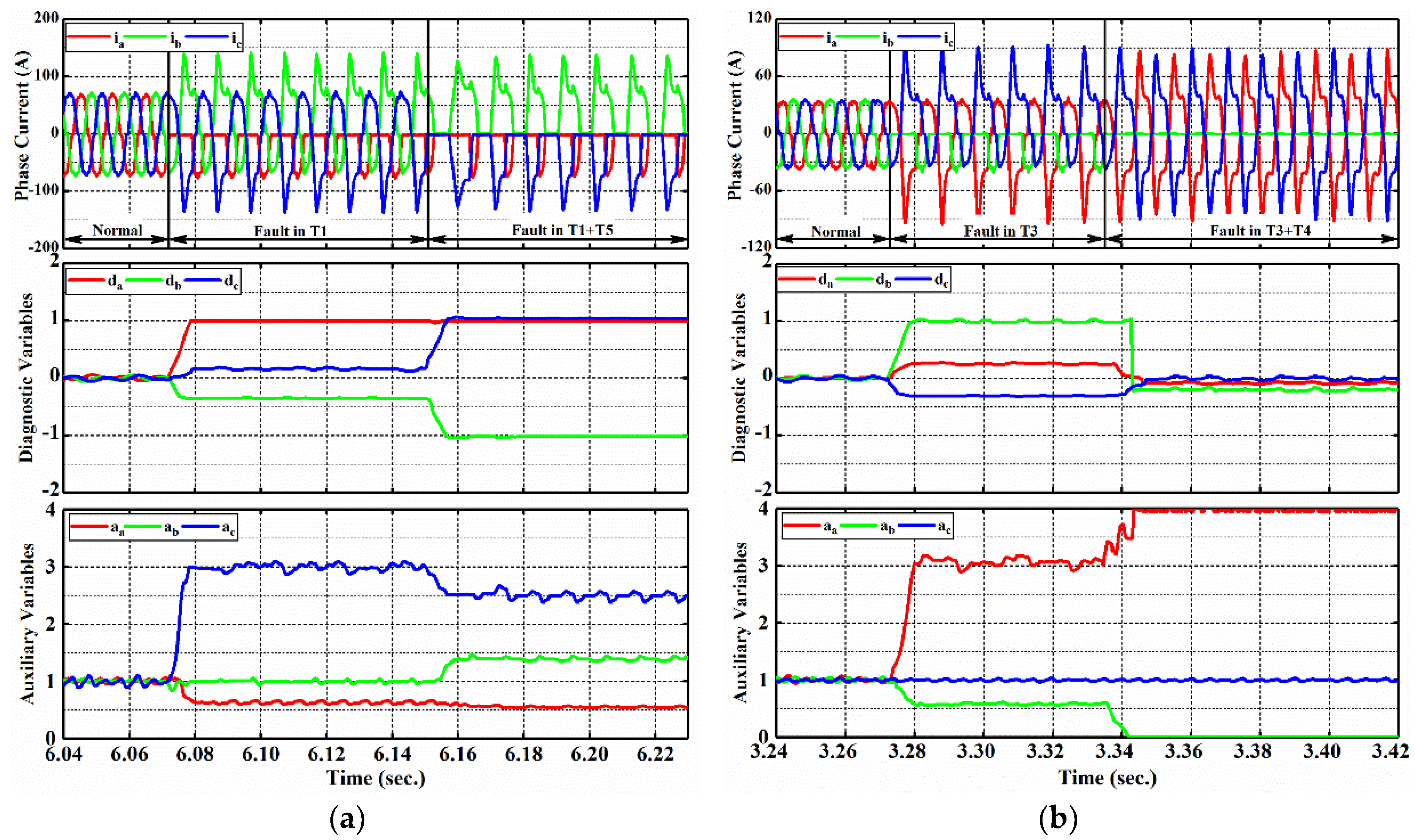
Figure 7a shows experimental results about phase currents, values of diagnostic variables and auxiliary variables when switches T1 and T5 are faulty under 100% of rated torque.
Similar to the aforementioned cases, phase currents are sinusoidal and symmetrical under normal condition, leading to normal diagnostic variables. When the occurrence of open fault in T1 comes, exceeds the identified and detected thresholds immediately, and converges to the final value 1. Unlike in previous conditions, since phase A and C are limited to flow only in negative direction together with phase B in positive direction, diagnostic variable is approximately −1 while other diagnostic variables are near 1. The lower leg in phase B seems to be broken-down, resulting in the distinction of the diagnosis, which is an indefinite factor for the algorithm. During this process, auxiliary variables are always in a safe state without false alarms.
Experimental results in Figure 7b underline the effectiveness of proposed algorithm in the case of both open circuit faults in same phase. When first fault in T3 occurs, the situation of diagnostic variables are same to the situation shown in Figure 6a, with the fault being identified in a time equivalent to 12% of the electrical period. However, after another fault in T4 is introduced, phase B current performs null over all period and the motor receives power from the remaining healthy phases. As a result, diagnostic variable and the remaining variables decrease to a value of zero considerably. During this process, current intermittently flows out a little due to the existence of reverse recovery diode. Consequently, the summation is zero while periodic average of current is exiting. Other phase currents perform as sinusoidal and symmetrical waveforms, so other diagnostic variables keep to near zero; thus, this fault requires auxiliary variables to detect the phase fault. As shown in Figure 7b, auxiliary variable converges to zero rapidly when fault in T4 occurs. At the same time, other auxiliary variables do not trigger the threshold . It should be noted that converges to an enormous value due to the absence of current in phase B. Thus, in this case, the amplitudes of is limited under a value of 4. Accordingly, phase failure can be detected by using diagnostic variables and auxiliary variables .
4.2.3. Load Variation Behavior
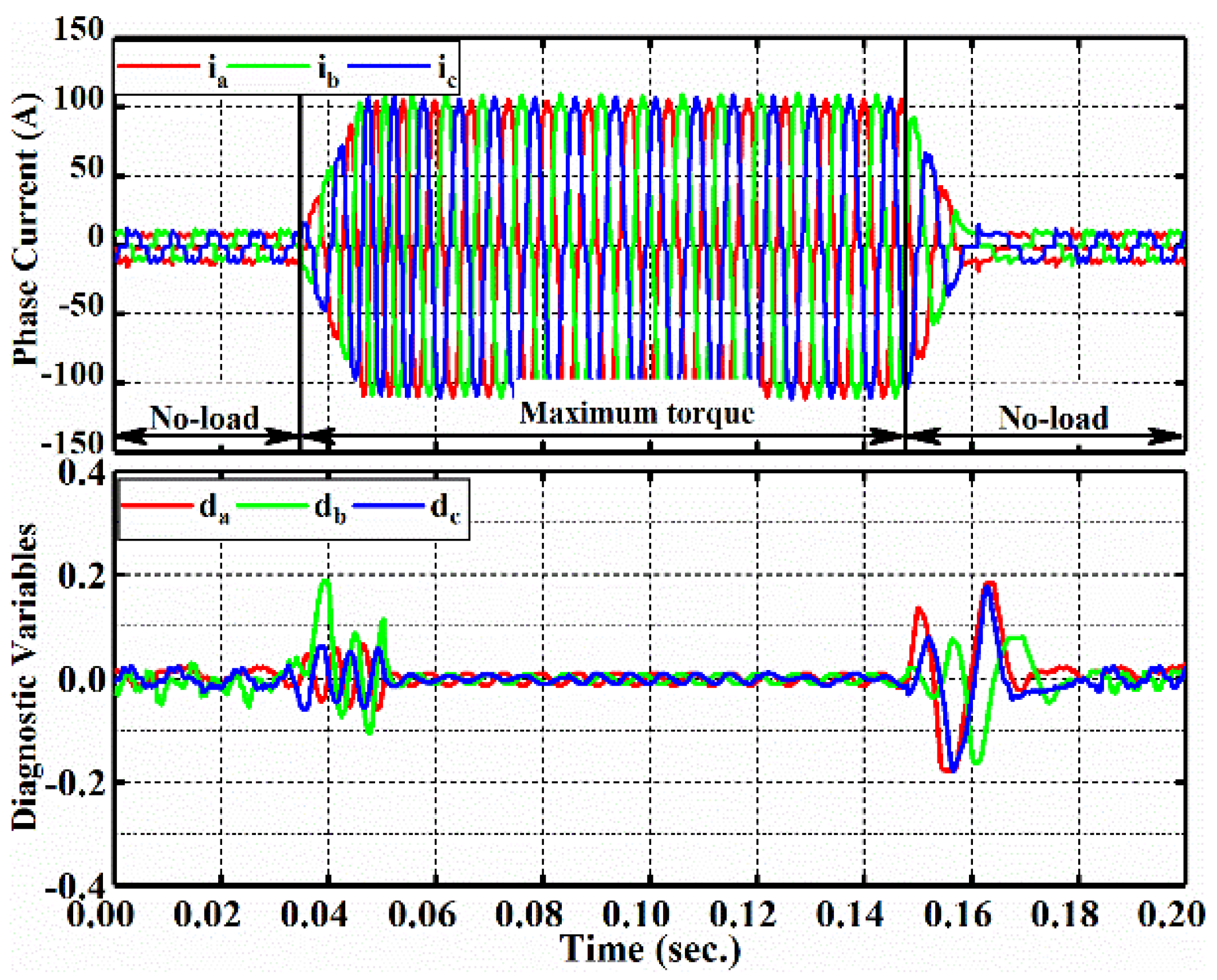
In order to validate the ability to resist interference and false alarms, a load variation condition where the transient torque command varies from zero to the maximum torque was performed under rated speed 720 rpm condition and the relevant results are presented in Figure 8. Since auxiliary variables are not relevant to this condition, their behaviors are not mentioned in this case. When load torque arises to the rated torque from zero in a very short time, the average value of summation with semi-periodic phase-difference slightly increases, resulting in the variations of diagnostic variables . Similarly, when torque command varies from maximum torque to free-load condition at t = 0.148 s, diagnostic variables increases slightly. Notwithstanding slight variation of diagnostic variables, the maximum value of diagnostic variables is near to 0.2 and it is always below the threshold . The experimental results in this case indicate that even under the severest torque variations, the amplitude of is less than considered identified threshold , which contributes significantly to the robustness of proposed algorithm. As mentioned in the introduction, the algorithm has the advantages in these aspects: practical application in electric vehicles, conciseness in the implemented process and the well-robustness against false alarms. The experimental results considering the different speed and load conditions show its effectiveness in dealing with the complex driving environment; furthermore, the result under severe torque variation condition proves the capacity against false alarms. The design process of the algorithm in Section 3 proves the conciseness and contributes to the less resource occupancy in digital signal processor.
4.2.4. Diagnostic Speed and Comparison
Generally speaking, diagnostic speed of proposed algorithm relies on the occurrence moment of the fault. For instance, if the fault is introduced in the top leg just during a positive current half-cycle, the variation of can be identified immediately because of the obstructed currents. Otherwise, if the fault is introduced in the top leg during a negative current half-cycle, the variation of can be observed only at the next half-cycle, leading to the slight time delay. Therefore, the optimal evaluation method is to ascertain the average diagnostic time based on fault occurrence moment; considering above the elements, a number of experiments are implemented and prove that diagnostic time can be shorter as 15.5% and longer as near 63.5% of the electrical period. Finally, proposed diagnostic algorithm has the average diagnostic time equivalent to about 38.5% of electric period.
The various diagnostic algorithms are addressed and compared in species such as their diagnostic time, ability to resist against false alarms and practicability in the drive system [9]. Among these algorithms, the modified DC current algorithm has the features of high ability to resist false alarms and independence of load variations; thus it is widely applied into the electric vehicles and it is selected as the contrasted method. The diagnostic speed between the both algorithms are summarized in Table 4, and the items are obtained according to a number of experimental results at 360 rpm and 30 Nm condition.
5. Conclusions
A practical real-time diagnostic algorithm for multiple IGBTs open circuit faults is proposed in this article. When open circuit faults in power switches occur, the corresponding half-bridge is obstructed and cannot produce the currents, resulting in the summation with semi-periodic phase-difference is non-zero value. Accordingly, diagnostic algorithm based on the normalization method and variable parameter moving average method is presented.
This algorithm requires only phase currents without extra sensors and referential signals, contributing to lower complexity of system and outside diagnostic devices. The experimental results present the effectiveness, fast-acting ability and practicability for electric vehicles. Meanwhile, this algorithm requires simple arithmetical operation and does not need various transformations, which have high significances for real-time capability.
Compared with other diagnostic algorithms that usually needs several fundamental periods, proposed algorithm is much faster and even only requires even 15.5% of electrical period. The main work in this paper concerns about the detection and localization of multiple IGBTs open circuit faults in the drive system and this algorithm is fundament of subsequent fault-tolerant control which is of great significance to the operation of the inverter in electric vehicles. However, the auxiliary diagnostic variables are obtained by dividing the absolute current values, which means the very big value of auxiliary diagnostic variables in some calculations. Therefore, the design of auxiliary diagnostic variables can be further improved. Besides, as illustrated in part 3, there may be ambiguous diagnosis in some specific cases due to the closed-loop currents, so the proposed algorithm requires further improvement.
Author Contributions
For this paper, all authors have participated in corresponding researches. Hongqian Wei conceived and designed the proposed algorithm; Lei Yu, Hongqian Wei, Mengzhu Zhang conceived and performed the experiments; Lei Yu and Hongqian Wei analyzed the data; Hongqian Wei wrote the paper. Khaled Teffah, Youtong Zhang and Mengzhu Zhang revised the English writing of this paper. All authors gave advice for the manuscript.
Conflicts of Interest
The authors declare no conflict of interest.
References
- Teng, F.; Mu, Y.; Jia, H.; Wu, J.; Zeng, P.; Strbac, G. Challenges on primary frequency control and potential solution from EVs in the future GB electricity system. Appl. Energy 2017, 194, 353–362. [Google Scholar] [CrossRef]
- Tie, S.; Tan, C. A review of energy sources and energy management system in electric vehicles. Renew. Sustain. Energy Rev. 2013, 20, 82–102. [Google Scholar] [CrossRef]
- Un-Noor, F.; Padmanaban, S.; Mihet-Popa, L.; Mollah, M.; Hossain, E. A comprehensive study of key electric vehicle (EV) components, technologies, challenges, impacts, and future direction of development. Energies 2017, 10, 1217. [Google Scholar] [CrossRef]
- Vaka, R.; Keshri, R.K. Review on contactless power transfer for electric vehicle charging. Energies 2017, 10, 636. [Google Scholar] [CrossRef]
- Zhu, Z.; Howe, D. Electrical machines and drives for electric, hybrid, and fuel cell vehicles. Proc. IEEE 2007, 95, 746–765. [Google Scholar] [CrossRef]
- Habib, S.; Khan, M.M.; Abbas, F.; Sang, L.; Shahid, M.U.; Tang, H. A comprehensive study of implemented international standards, technical challenges, impacts and prospects for electric vehicles. IEEE Access 2018, 6, 13866–13890. [Google Scholar] [CrossRef]
- Smet, V.; Forest, F.; Huselstein, J.J.; Richardeau, F.; Khatir, Z.; Lefebvre, S.; Berkani, M. Ageing and failure modes of IGBT modules in high-temperature power cycling. IEEE Trans. Ind. Electron. 2011, 58, 4931–4941. [Google Scholar] [CrossRef]
- Lu, B.; Sharma, S.K. A literature review of IGBT fault diagnostic and protection methods for power inverters. IEEE Trans. Ind. Appl. 2009, 45, 1770–1777. [Google Scholar]
- Henao, H.; Capolino, G.A.; Fernandez-Cabanas, M.; Filippetti, F.; Bruzzese, C.; Strangas, E.; Pusca, R.; Estima, J.; Riera-Guasp, M.; Hedayati-Kia, S. Trends in fault diagnosis for electrical machines a review of diagnostic techniques. IEEE Ind. Electron. Mag. 2014, 8, 31–42. [Google Scholar] [CrossRef]
- Yang, Z.; Chai, Y. A survey of fault diagnosis for onshore grid-connected converter in wind energy conversion systems. Renew. Sustain. Energy Rev. 2016, 66, 345–359. [Google Scholar] [CrossRef]
- Yang, S.; Bryant, A.; Mawby, P.; Xiang, D.; Ran, L.; Tavner, P. An industry-based survey of reliability in power electronic converters. IEEE Trans. Ind. Appl. 2011, 47, 1441–1451. [Google Scholar] [CrossRef]
- Zhang, L.; Hu, Y.; Huang, W. Fault diagnosis and tolerant techniques of inverter in three-phase variable frequency drive system. Trans. China Electrotech. Soc. 2004, 19, 1–5. [Google Scholar]
- Sang, Z.; Mao, C.; Lu, J.; Wang, D. Analysis and simulation of fault characteristics of power switch failures in distribution electronic power transformers. Energies 2013, 6, 4246–4268. [Google Scholar] [CrossRef]
- Jacobina, C.B.; Ribeiro, R.L.D.; Lima, A.M.N.; da Silva, E.R.C. Fault-tolerant reversible AC motor drive system. IEEE Trans. Ind. Appl. 2003, 39, 1077–1084. [Google Scholar] [CrossRef]
- Freire, N.M.A.; Estima, J.O.; Cardoso, A.J.M. A voltage-based approach without extra hardware for open-circuit fault diagnosis in closed-loop PWM AC regenerative drives. IEEE Trans. Ind. Electron. 2014, 61, 4960–4970. [Google Scholar] [CrossRef]
- Ge, X.; Pu, J.; Gou, B.; Liu, Y. An open-circuit fault diagnosis approach for single-phase three-level neutral-point-clamped converters. IEEE Trans. Power Electron. 2018, 33, 2559–2570. [Google Scholar] [CrossRef]
- Mendes, A.M.S.; Cardoso, A.J.M. Voltage source inverter fault diagnosis in variable speed AC drives, by the average current Park’s vector approach. In Proceedings of the International Conference on Electric Machines and Drives, Seattle, WA, USA, 9–12 May 1999; pp. 704–706. [Google Scholar]
- Freire, N.M.A.; Estima, J.O.; Cardoso, A.J.M. Multiple open-circuit fault diagnosis in voltage-fed PWM motor drives using the current Park’s Vector phase and the currents polarity. In Proceedings of the 8th IEEE Symposium on Diagnostics for Electrical Machines, Power Electronics & Drives, Bologna, Italy, 5–8 September 2011; pp. 397–404. [Google Scholar]
- Rothenhagen, K.; Fuchs, F.W. Performance of diagnosis methods for IGBT open circuit faults in three phase voltage source inverters for AC variable speed drives. In Proceedings of the 2005 European Conference on Power Electronics and Applications, Dresden, Germany, 11–14 September 2005; pp. 10–17. [Google Scholar]
- Sleszynski, W.; Nieznanski, J.; Cichowski, A. Open-transistor fault diagnostics in voltage-source inverters by analyzing the load currents. IEEE Trans. Ind. Electron. 2009, 56, 4681–4688. [Google Scholar] [CrossRef]
- Zidani, F.; Diallo, D.; Benbouzid, M.E.H.; Nait-Said, R. A fuzzy-based approach for the diagnosis of fault modes in a voltage-fed PWM inverter induction motor drive. IEEE Trans. Ind. Electron. 2008, 55, 586–593. [Google Scholar] [CrossRef] [Green Version]
- Park, B.G.; Lee, K.J.; Kim, R.Y.; Kim, T.S.; Ryu, J.S.; Hyun, D.S. Simple fault diagnosis based on operating characteristic of brushless direct-current motor drives. IEEE Trans. Ind. Electron. 2011, 58, 1586–1593. [Google Scholar] [CrossRef]
- Estima, J.O.; Cardoso, A.J.M. A new algorithm for real-time multiple open-circuit fault diagnosis in voltage-fed PWM motor drives by the reference current errors. IEEE Trans. Ind. Electron. 2013, 60, 3496–3505. [Google Scholar] [CrossRef]
- Estima, J.O.; Cardoso, A.J.M. A new approach for real-time multiple open-circuit fault diagnosis in voltage-source inverters. IEEE Trans. Ind. Appl. 2011, 47, 2487–2494. [Google Scholar] [CrossRef]
- Yu, L.; Zhang, Y.; Huang, W.; Teffah, K. A fast-acting diagnostic algorithm of insulated gate bipolar transistor open circuit faults for power inverters in electric vehicles. Energies 2017, 10, 552. [Google Scholar] [CrossRef]
- Yan, H.; Xu, Y.; Cai, F.; Zhang, H.; Zhao, W.; Gerada, C. PWM-VSI fault diagnosis for PMSM drive based on fuzzy logic approach. IEEE Trans. Power Electron. 2018. [Google Scholar] [CrossRef]
- Shao, S.; Wheeler, P.W.; Clare, J.C.; Watson, A.J. Fault detection for modular multilevel converters based on sliding mode observer. IEEE Trans. Power Electron. 2013, 28, 4867–4872. [Google Scholar] [CrossRef]
- Zhao, J.; Gao, X.; Li, B.; Liu, X.; Guan, X. Open-phase fault tolerance techniques of five-phase dual-rotor permanent magnet synchronous motor. Energies 2015, 8, 12810–12838. [Google Scholar] [CrossRef]
- Hong, Y.; Wei, Y.; Chang, Y.; Lee, Y.; Liu, P. Fault detection and location by static switches in microgrids using wavelet transform and adaptive network-based fuzzy inference system. Energies 2014, 7, 2658–2675. [Google Scholar] [CrossRef]
- Charfi, F.; Sellami, F.; Al-Haddad, K. Fault diagnostic in power system using wavelet transforms and neural networks. In Proceedings of the 2006 IEEE International Symposium on Industrial Electronics, Montreal, QC, Canada, 9–13 July 2006; pp. 1143–1148. [Google Scholar]
- Yu, L.; Zhang, Y.; Huang, W. Accurate and efficient torque control of an interior permanent magnet synchronous motor in electric vehicles based on hall-effect sensors. Energies 2017, 10, 410. [Google Scholar] [CrossRef]
Figure 1.
Schematic diagram of three-phase inverter system.

Figure 2.
Performance of phase current with occurrence of T1 fault at 360 rpm/30 Nm condition.

Figure 3.
Diagram of realization of proposed algorithm.

Figure 4.
Experimental bench. PMSM: permanent magnet synchronous motor.

Figure 5.
Diagram of drive system with open circuit fault diagnostic algorithm in experimental setup.
Figure 5.
Diagram of drive system with open circuit fault diagnostic algorithm in experimental setup.

Figure 6.
Experimental results about waveforms of phase currents, diagnostic variables and auxiliary variables for referential speed of 720 rpm: (a) Open circuits in T3 and T6 under 100% of rated torque; (b) open circuits in T2 and T5 under 60% of rated torque.
Figure 6.
Experimental results about waveforms of phase currents, diagnostic variables and auxiliary variables for referential speed of 720 rpm: (a) Open circuits in T3 and T6 under 100% of rated torque; (b) open circuits in T2 and T5 under 60% of rated torque.

Figure 7.
Experimental results about waveforms of phase currents, diagnostic variables and auxiliary variables for referential speed of 360 rpm: (a) Open circuits in T1 and T5 under 100% of rated torque; (b) open circuits in T3 and T4 under 60% of rated torque.
Figure 7.
Experimental results about waveforms of phase currents, diagnostic variables and auxiliary variables for referential speed of 360 rpm: (a) Open circuits in T1 and T5 under 100% of rated torque; (b) open circuits in T3 and T4 under 60% of rated torque.

Figure 8.
Experimental results about waveforms of phase currents and diagnostic variables under the load variations at rated speed of 360 rpm.
Figure 8.
Experimental results about waveforms of phase currents and diagnostic variables under the load variations at rated speed of 360 rpm.


Table 1.
Detect of single open circuit fault.
| Faulty Switch | ||||
|---|---|---|---|---|
| Phase A | T1 | |||
| T2 | ||||
| Phase B | T3 | |||
| T4 | ||||
| Phase C | T5 | |||
| T6 | ||||
Table 2.
Localization of multiple insulated gate bipolar transistor (IGBT) open circuit faults.
| Items | Diagnostic Variable | Auxiliary Variable | |||||
|---|---|---|---|---|---|---|---|
| Da | Db | Dc | Aa | Ab | Ac | ||
| Single IGBT fault | T1 | P | 0 | 0 | H | H | H |
| T3 | 0 | P | 0 | H | H | H | |
| T5 | 0 | 0 | P | H | H | H | |
| T2 | N | 0 | 0 | H | H | H | |
| T4 | 0 | N | 0 | H | H | H | |
| T6 | 0 | 0 | N | H | H | H | |
| Phase fault | T1&T2 | 0 | 0 | 0 | L | H | H |
| T3&T4 | 0 | 0 | 0 | H | L | H | |
| T5&T6 | 0 | 0 | 0 | H | H | L | |
| Double faults from crossed half-bridges | T1&T4 | P | N | 0 | H | H | H |
| T1&T6 | P | 0 | N | H | H | H | |
| T3&T2 | N | P | 0 | H | H | H | |
| T3&T6 | 0 | P | N | H | H | H | |
| T5&T2 | N | 0 | P | H | H | H | |
| T5&T4 | 0 | N | P | H | H | H | |
| Two upper IGBTs faults | (T1&T3)&[T6] | P | P | N | H | H | H |
| (T1&T5)&[T4] | P | N | P | H | H | H | |
| (T3&T5)&[T2] | N | P | P | H | H | H | |
| (T2&T4)&[T5] | N | N | P | H | H | H | |
| (T2&T6)&[T3] | N | P | N | H | H | H | |
| (T4&T6)&[T1] | P | N | N | H | H | H | |
| Multiple faults with phase failure | (T1&T2)&(T3|T6) | 0 | P | N | L | H | H |
| (T1&T2)&(T4|T5) | 0 | N | P | L | H | H | |
| (T3&T4)&(T1|T6) | P | 0 | N | H | L | H | |
| (T3&T4)&(T2|T5) | N | 0 | P | H | L | H | |
| (T5&T6)&(T1|T4) | P | N | 0 | H | H | L | |
| (T5&T6)&(T2|T3) | N | P | 0 | H | H | L | |
Note: ‘[]’ means that switch’s status is not certain. ‘|’ means at least one fault occurrence.
Table 3.
Parameters of used PMSM.
| Parameters | Symbol | Value |
|---|---|---|
| Rated power | 2.3 kW | |
| Rated torque | 30 Nm | |
| Battery Voltage | 120 V | |
| Peak phase current | 80 A | |
| Number of pole pairs | p | 16 |
| Phase resistance | 21.55 mH | |
| Magnet flux-linkage | 0.0256 Wb | |
| -axis inductance | 124 µH | |
| -axis inductance | 124 µH | |
| Moment of inertia | 0.0035 kg·m2 |
Table 4.
Results about the diagnostic speed.
| Items | Diagnostic Time (% of Current Period) | ||
|---|---|---|---|
| Minimum | Average | Maximum | |
| Normal algorithm [19] | 33 | 79.5 | 125 |
| Proposed algorithm | 15.5 | 38.5 | 63.5 |
© 2018 by the authors. Licensee MDPI, Basel, Switzerland. This article is an open access article distributed under the terms and conditions of the Creative Commons Attribution (CC BY) license (http://creativecommons.org/licenses/by/4.0/).
Share and Cite
MDPI and ACS Style
Wei, H.; Zhang, Y.; Yu, L.; Zhang, M.; Teffah, K. A New Diagnostic Algorithm for Multiple IGBTs Open Circuit Faults by the Phase Currents for Power Inverter in Electric Vehicles. Energies 2018, 11, 1508. https://doi.org/10.3390/en11061508
AMA Style
Wei H, Zhang Y, Yu L, Zhang M, Teffah K. A New Diagnostic Algorithm for Multiple IGBTs Open Circuit Faults by the Phase Currents for Power Inverter in Electric Vehicles. Energies. 2018; 11(6):1508. https://doi.org/10.3390/en11061508
Chicago/Turabian StyleWei, Hongqian, Youtong Zhang, Lei Yu, Mengzhu Zhang, and Khaled Teffah. 2018. "A New Diagnostic Algorithm for Multiple IGBTs Open Circuit Faults by the Phase Currents for Power Inverter in Electric Vehicles" Energies 11, no. 6: 1508. https://doi.org/10.3390/en11061508
Note that from the first issue of 2016, this journal uses article numbers instead of page numbers. See further details here.