Design Criterion of Damper Component of Passive-Type Mount Module without Using Base Mass-Block


Department of mechanical design engineering, Pukyong National University, Busan 48547, Korea
Energies 2018, 11(6), 1548; https://doi.org/10.3390/en11061548
Submission received: 12 May 2018
/
Revised: 10 June 2018
/
Accepted: 11 June 2018
/
Published: 13 June 2018
Abstract
:Passive-type mount modules have been used frequently to isolate excitation from the target mechanical system, and electric power plants use the mount devices to control the harmonic excitation source from a combustion engine. The mount structure is composed of a spring component, a stacked thin-panel, and a heavy base-mass block, and installation as well as maintenance of the structures are difficult. To tackle this problem associated with mount modules, I investigate in this work the feasibility of a simplified mount module with no base mass-block; the harmonic frequency of interest was selected from 30 (Hz) to 120 (Hz) owing to the constant rotating speed of the combustion engine at 1800 (rev/min). The design criterion of the damper components was formulated from the response index at the electric power plant, and the influence of the damper component at the proposed mount was calculated theoretically from the linearized system models. The theoretical result was compared with the measured response index at the electric power plant, and the comparison result revealed the superior capability of the proposed mount module in controlling the reaction motion at the electric power plant.
1. Introduction
A passive-type mount device is widely used in a mechanical system to support the mechanical system as well as to isolate any force or motion between two neighboring components. The passive mount module has many advantages, such as relatively low cost of manufacturing and easy installation and maintenance. The conventional type of passive mount module is a relatively simple structural device whose principal subcomponents are springs, dampers, or other mechanical devices. The control of the isolation performance can be achieved through the selection of the relevant mechanical components, and the equivalent nature of mechanical properties, stiffness, and damping coefficient are very important to change the dynamic response of the supporting system as well as the isolation performance under several different excitation sources from the target system or basement.
The mount module or the vibration isolation device is used in many industries, including transportation, heavy industry, and power plants, and many isolation devices have been invented to cope with excitation sources. Mount modules can be divided into three categories according to the controllability of mechanical properties, namely, passive type, semi-active type, and active-type mount. The mount type proposed in this study is a passive-type mount model. Semi-active-type mounts inherit technical advantages from both active-type and passive-type mounts so that the performance of vibration isolation is superior compared to the passive-type mounts owing to the adaptive capability of the suspension coefficient in certain environmental conditions. The installation cost can be saved and the control risks from accidents caused by malfunctions can be eliminated in the case of the full-active-type mount device [1,2,3,4]. The active-type mount is the best vibration isolator device to apply control theory to achieve optimal performance in every operational condition or excitation situation [5,6,7,8,9,10]. However, many costs are incurred during the integration process, such as system monitoring using several sensors, and the active-type mount may require additional mechanical redundancy to cope with any faults related to the active controller. On the other hand, the passive-type mount is used in a wide range of industrial applications since a variety of mass-produced devices are manufactured according to the required specifications, i.e., payload and frequency range. Compared to the other types of mount modules, semi-active or full-active, the conventional passive-type mount device is cost-effective and has a relatively simple structure, which makes it easy to install. For decades, many mechanisms related to passive-type mount modules have been studied for different target systems to control the transmissibility of vibration responses [11,12,13,14,15,16]. Since the variation of mechanical properties is not allowable in a passive-type mount device, the system identification and the reliable design sensitivity should be performed during the selection of the characteristics of the mount module [17,18,19,20], and this is difficult in the case of nonlinear behavior in either the mount module itself or the relevant supporting system [21,22,23]. One of the applications of passive-type mount modules is in a power plant in which they are operated in emergency events, such as blackouts, to isolate the harsh excitation arising from the internal combustion engine.
The conventional power plant is heavy mechanical system having a high capacity of internal combustion engine, and its specific weight is dependent on the electric capacity. Hence, the reaction motion of the power plant from the supporting mount or the acceleration transmission to the basement floor is large enough to damage the power plant or the neighboring buildings during operation. The operation of the internal combustion engine is usually set for a constant rotating speed, i.e., 1800 (rev/min), and the reciprocal forces from the combustion engine show harmonic excitation owing to the kinematics of crank-sliding mechanisms. To address this problem, the passive-type mount module is installed to support the heavy power plant to protect both the power plant and the installed building from the harmonic excitation. The target system considered in this study is the emergency power plant of 750 KW capacity, manufactured by DAEHUNG Electric Machinery Company in South Korea. The current mount module consists of multiple mechanical components; the power plant is supported by spring components, and an additional base mass-block is attached beneath the supporting spring. In addition, a thin-panel of damping material is used to wrap all faces of the base mass-block on the floor of the building, making the current mount module expensive with regard to installation and maintenance costs. By using a simplified mount device to support the electric power plant, practical problems regarding the current mount module can be addressed effectively. A previous study has investigated the feasibility of the simplified mount module with no base mass-block for the same target electric power plant, but no theoretical approaches were carried out to determine why the reaction motion at the power plant with the proposed mount module is smaller than with the current mount module [24]. In addition, the system modeling of the supported mount module was more specifically considered in this study as compared to previous studies so that the discrepancy between the experimental and the predicted results could be minimized in the current form.
The feasibility of a simplified mount module is the main issue studied in this work. Given the two objectives of vibration isolation, namely, transmissibility of vibration response to the base floor and reaction motion from the supporting mount [25,26], the reaction motion at the power plant is determined to design a criterion for the damper component for the simplified mount module. Two equivalent theoretical models that include the power plant are derived from different supporting mount modules, and the motion at the power plant is derived theoretically from the frequency response function between the operational force at the power plant and the response motion at the same location. Frequencies of interest are selected as harmonic frequencies, 30 (Hz), 60 (Hz), 90 (Hz), and 120 (Hz), corresponding to the rated operational frequency of the combustion engine at 1800 (rev/min). The response index [26] is introduced to compare the response motion at the power plant by dividing the response under the proposed mount with the response under the current mount, and the design criterion regarding the damper component is defined as the value of response index less than 1. The theoretical consequences are verified with experimental measurements under 100% electric load of the power plant, and this event was selected because vibration responses are most severe at this operational condition. Spectral responses at the location of interest will show similar pattern as compared to other operation events, such as no electric load or 50% load, because the excitation source, or combustion engine, is operated at the constant rotating speed at 1800 (rev/min).
2. System Modeling of Electric Power Plant
2.1. Electric Power Plant with Current Passive Mount Module
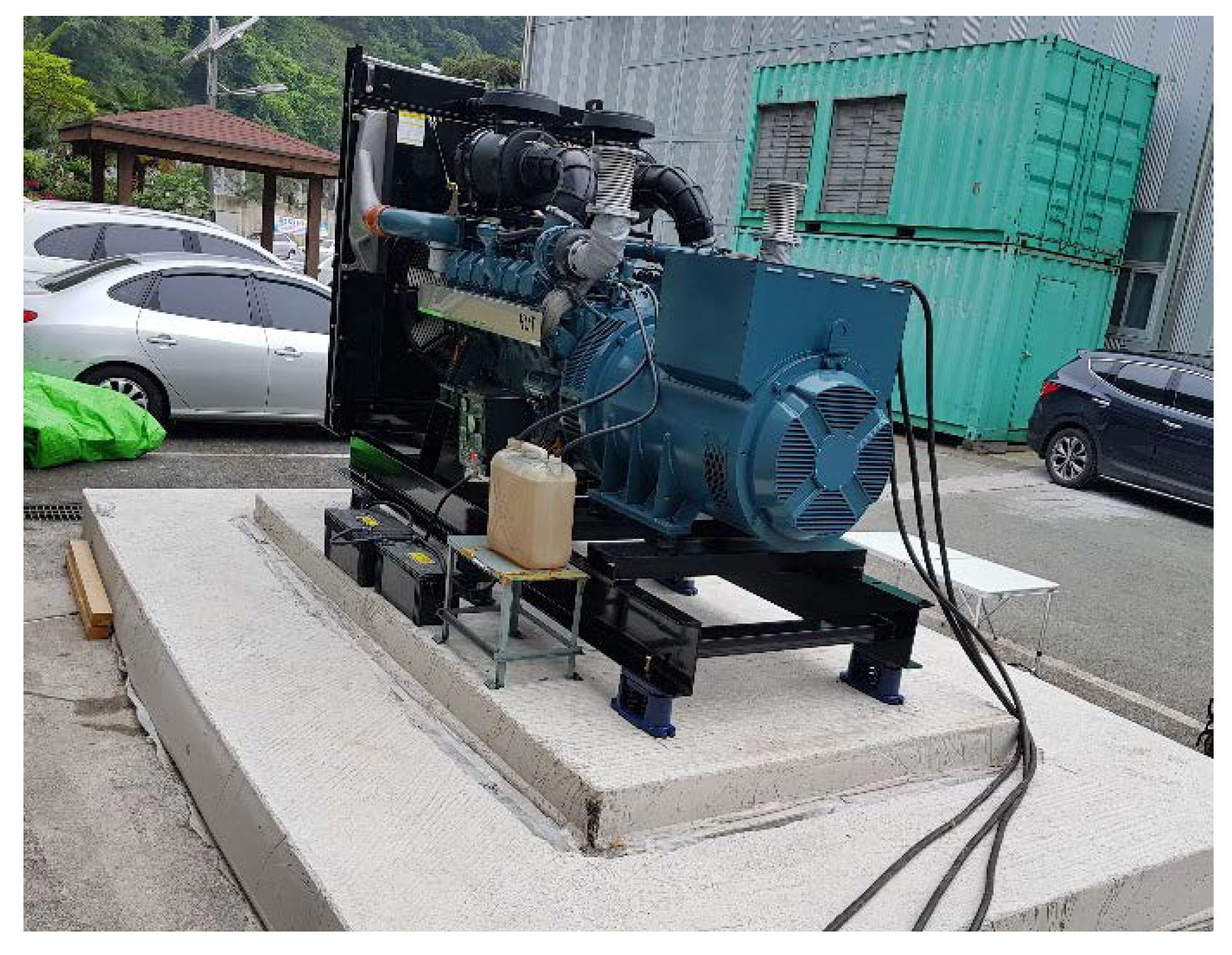
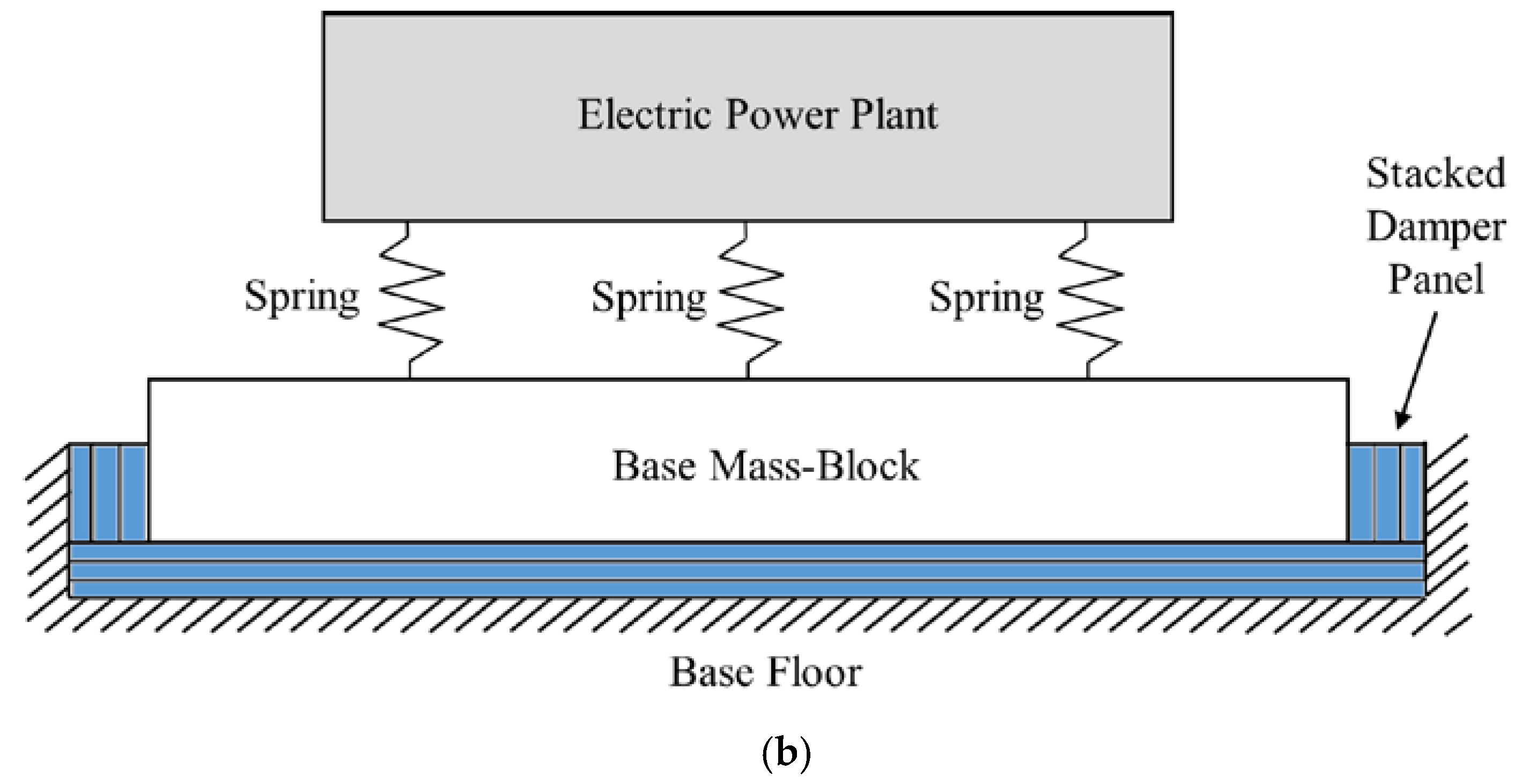
The electric power plant of capacity 750 KW (see Table 1) was built in the basement floor of a building to supply sufficient electric energy in the case of emergency accidents such as blackouts as illustrated in Figure 1. When the electric power level was dropped suddenly, the combustion engine operated at the constant rotating speed of 1800 (rev/min) to generate electric energy, and the reciprocal excitation forces were triggered as follows. To tackle the vibration problem, the mount module should be attached to support the heavy-weighted power plant to minimize the effect of transmissibility to the basement floor or the reaction motion at the relevant power plant. The current mount module consisted of several mechanical components, such as spring, damper, and base mass-block. The spring supported the target power plant directly, and the base mass-block was located beneath the spring component. A thin-panel of damping material was attached to all the faces of the base mass-block on the building floor to isolate the transmitted excitation of the base mass-block. The side view of the current mount module and the mount diagram are shown in Figure 2a,b, respectively.
Since the current mount module consists of several subcomponents including heavy base mass-block, several problems regarding the current device, i.e., rigorous installation process, increased manufacturing cost, and difficulty in maintenance, were reported. Hence, the current mount module needs to be replaced with a simplified mount structure with no base mount module if similar isolation performance can be promised.
The feasibility of the simplified mount was studied using the equivalent power plant model including the supporting mount module. The theoretical power plant was modeled with three concentrated masses, electric power plant (), base mass-block () and basement floor (), and one spring component () was placed between the power plant and the base mass-block. Here, the parallel springs in Figure 2a were expressed with the equivalent stiffness coefficient The small damping characteristics of the spring component was modeled as . The thin panel of damping material attached to all faces of the base mass-block on the basement floor was expressed in terms of both damping coefficient () and spring coefficient (), respectively. The building or the basement floor was assumed to be a rigid body with both a large mass ( and a loose spring (). Here, the coefficients on the damper panel, and , have considerably high values compared to spring components, and . Those conditions can be derived because the small damping effect on spring components can be derived from the nonlinear behavior of the spring, and the reactive displacement from the damper panel is very conservative for the compressive load. The mechanical properties of the basement floor, and , are virtually introduced to consider the relevant building floor as a rigid body. The equivalent model of the electric power plant supported by the current mount module is illustrated in Figure 3, and the mechanical characteristics of and measured separately using the damper testing machine (835 model, Systems Corporation/U.S.A., Minnesota (MTS)) are summarized in Table 2. The mechanical properties of the damper panel (both and ) could not be directly measured using the same test equipment because the identification test should be conducted under the static load, 1000 kgf, to mimic the actual static supporting condition so that large values of the two variables, and , approach the limitation of measurable scope of this equipment. In addition, all coefficients applied for the system modeling were equivalent values suitable for the prediction of power plant motion so that the selection of both variables, and , were proceeded by considering the target response for external force. Hence, two mechanical properties are searched based on the indirect identification process by tuning variables from the comparison of the frequency response function. Here, the selected four points are the major harmonic frequencies of interest at the operating speed of 1800 (rev/min).
The governing equations regarding the equivalent power plant model in Figure 3 were derived as from (1a) to (1c) by assigning as the equivalent force from the combustion engine. The response motion of interest is the location of the electric power plant, , and the frequency response function between external force and response motion can be derived in the s-domain as shown in Equation (2).
2.2. Electric Power Plant with Proposed Passive Mount Module
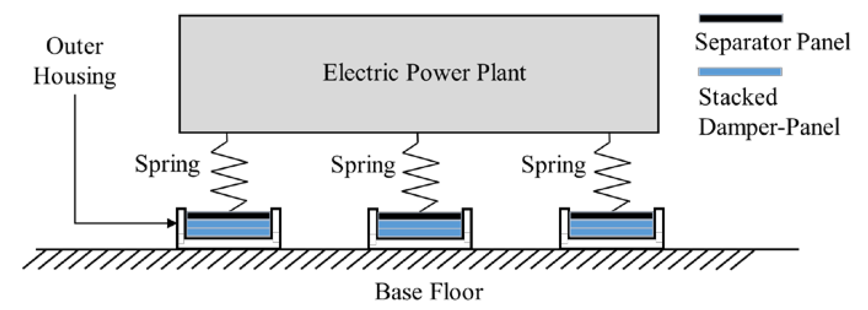
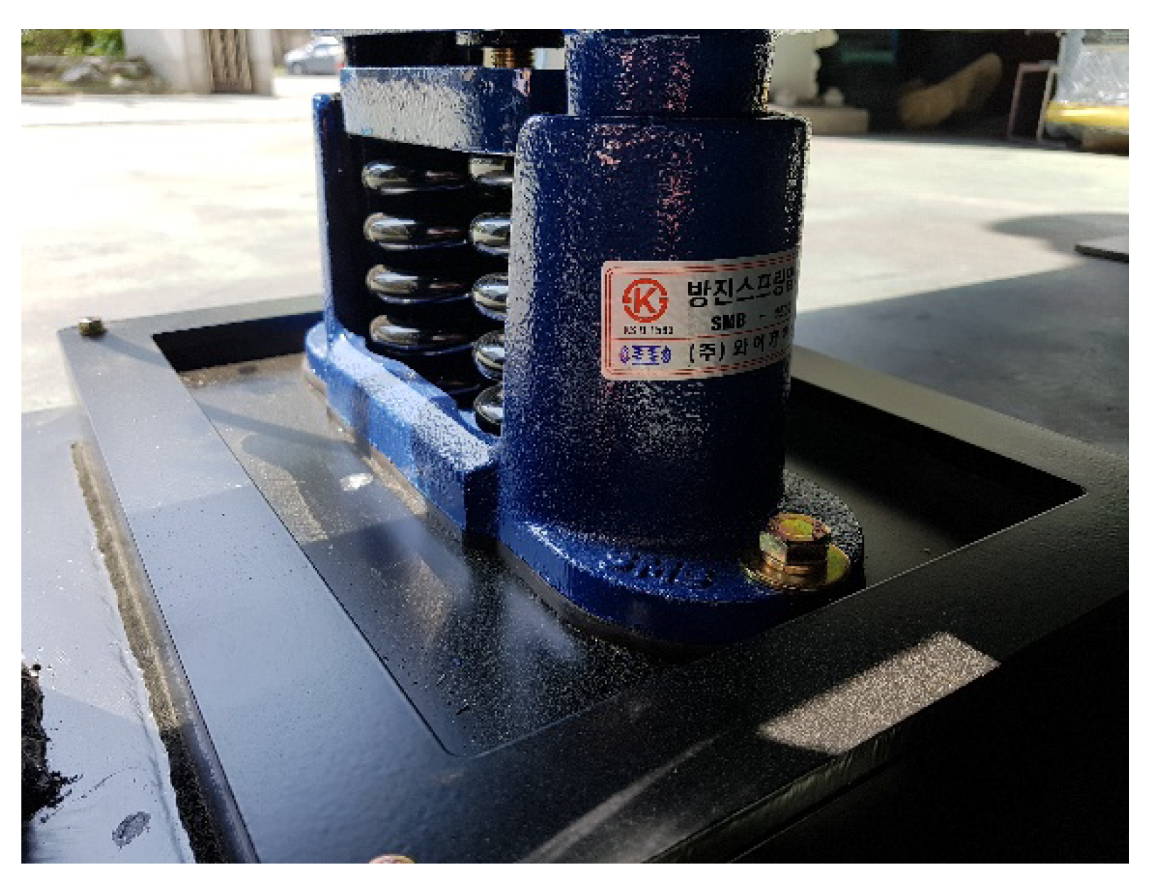
Most of the practical problems regarding the current mount module is related to the base mass-block so that the simplified mount module is proposed with no base mass-block. The same spring component () was designed to be attached at the same position of the main plant frame to support the electric power plant since few other spring components can be used as supporting springs in the case of heavy payloads. Hence, the damper component ( and ) was selected as the key design component to enhance the characteristics of vibration isolation by attaching it at the serial location with the spring component as shown in Figure 4. Here, the mass of steel frames, both the separator panel between the spring and the damper panel and the outer housing frame containing all stacked thin panels of damping material, were assumed to be negligible owing to the relatively small mass contribution. The equivalent coefficients of damper component, and , can be controlled by selecting the number of stacked thin panels of damping material. The prototype mount module is prepared using only one spring and one damper component with no base mass-block so that the proposed mount module can be constructed as a sound-compact structure as illustrated in Figure 5.
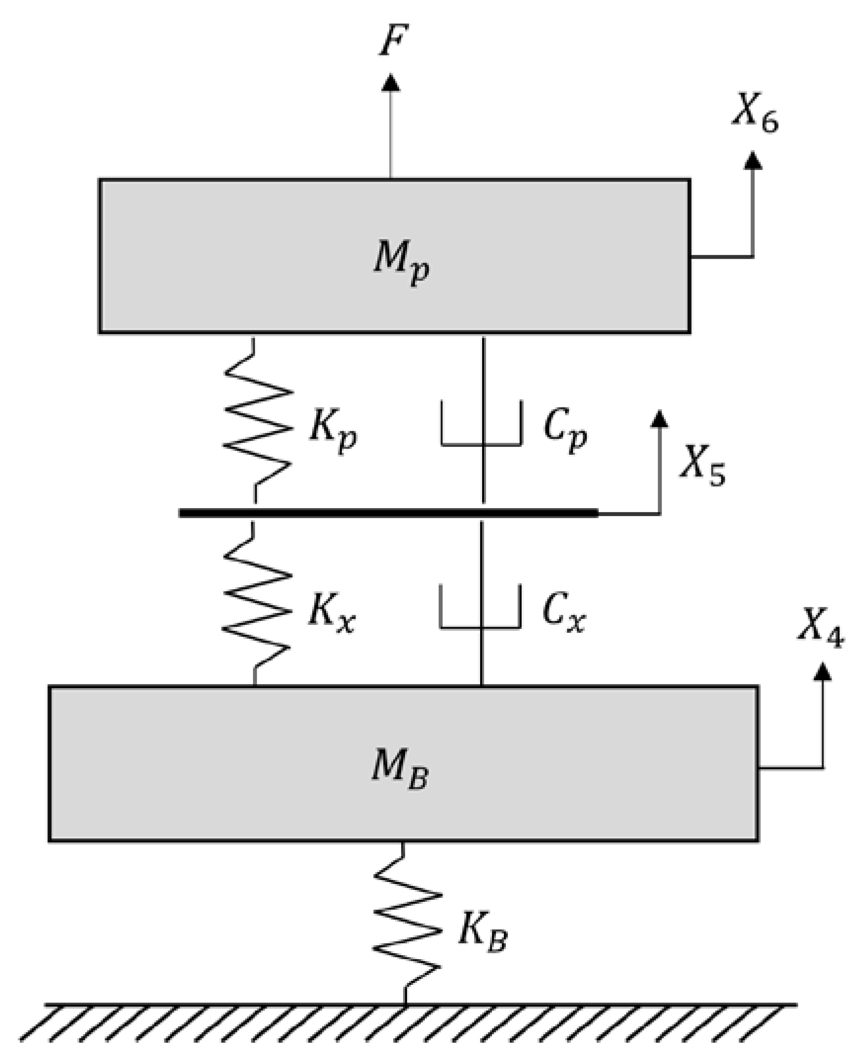
The system modeling of the electric power plant with the simplified mount module was conducted to build the equivalent supported power plant as shown in Figure 6. Here, the serial location of the spring component and the damper component was designed as supporting mount device in an electric power plant, and each component was modelled with both spring and damping coefficients, respectively. The mass of separator panel (see Figure 4) was assumed to be small enough to neglect it at the system model. The frequency response function between the excitation from the power plant, , and the response at the plant location, , was derived from the governing equations in a time domain as Equations (3a)–(3c) and the formula can be expressed in Equation (4) in a s-domain. The main difference in system modeling with the current mount module shown in Figure 3 is that the heavy base mass-block is not installed in the electric power plant.
3. Design Criterion of Damper Component
The feasibility of the proposed mount module can be evaluated using two equivalent system models discussed in the previous section by comparing the response motion of the electric power plant arising from the same excitation condition. Therefore, the criterion was focused on the response comparison at the harmonic frequencies of interest for different supporting mount cases, and the response index function was introduced to compare the isolation capacity of the relevant mount module divided by two frequency responses in Equations (2) and (4) [24]. The following response index can be calculated as the scalar value in the frequency domain that is equal to the relative capacity of the proposed mount module with respect to the current module as shown in Equation (5). This response index is an efficient function because the force data, which are not a factor of interest, can be cancelled out during calculation.
The theoretical response index was calculated from the equivalent systems. Six supporting mount modules were installed in parallel position so that the variables applied for the two equivalent models were determined from the information presented in Table 1 and Table 2 and summarized in Table 3. Here, (=6900 kg) was determined by the design guideline from DAEHUNG Electric Machinery Company.
Variables regarding the basement floor, and , were selected to facilitate considering the neighboring building as a rigid body by relating with two variables, and , respectively. Both the equivalent stiffness and damping in the damper panel were calculated indirectly by comparing the theoretical frequency response function in Equation (2) with the experimental result. The experimental frequency response function was measured by the impact testing with both an impact hammer, and the response acceleration and comparison was performed for frequency points of interest: 30 (Hz), 60 (Hz), 90 (Hz) and 120 (Hz). The adjusted variables related to the damper panel, and , were derived as shown in Table 3, and those values are not measured values but tuned variables according to the minimization policy of the spectral errors in the two frequency response functions as illustrated in Figure 7.
Since the response at the power plant should be minimized as soon as possible to protect the electric power plant, the criterion of the response index () is equal to or less than one in all frequency points of interest. If the inverse of the frequency response function in the current mount module is defined as function , the criterion regarding the response index can be rewritten as follows.
The frequency response function in Equation (4) can be approximately simplified considering the relationship between variables in frequency range of interest. Both coefficients in damper component, and , were not determined so far, but the physical values cannot exceed much from the listed variables in Table 3 so that terms, and , are much higher than other terms and . In addition, since both coefficients in damper component, and , are much larger than coefficients in spring component, and , respectively, Equation (4) can be simplified as follows.
The design criterion in Equation (6) can be reformulated more simply by using Equation (7) as shown in Equation (8).
The left term in Equation (8) can be calculated according to the harmonic frequencies of interest, and the theoretical calculations are summarized in Table 4. Here, the equivalent coefficients ( and ) in damper component did not contribute at all due to the canceling out of all relevant variables during the approximation in Equation (7).
The calculation result reveals that the criterion in Equation (6) was satisfied with a sufficient margin so that the proposed mount module can be used instead of the current mount module with respect to the reaction motion at the power plant location. In particular, all coefficients in damper component have no effect on the simplified response index in Equation (8) so that the selection of suitable damper component seems to be very flexible during the manufacturing process of the proposed mount module. In addition, the theoretical index also can be derived directly from the two frequency response functions, expressed as Equations (2) and (4). The simulation result is summarized in Table 5 for three damping coefficients. Here, the stiffness coefficient of damper component was fixed as 43,990 (kN/m) (= when 120 (Hz) in Table 3), for example.
The response index in both Table 4 and Table 5 showed very similar values in all harmonic frequencies of interest, and the approximation in Equation (8) may be the reasonable formula for the criterion of damper coefficient. The reason for little contribution of the damper component can be found from the operation range of the electric power plant as shown in Figure 7. Since the supported electric power plant has been designed to locate the fundamental frequency far less than the operating frequency range, 30 (Hz), the response motion at the power plant is subjective to the mass factor. If the operating frequency range is changed according to the rotating speed of the combustion engine, the response index will be also changed since the assumption in Equation (8) will not be valid then. The little contribution of damper component will not promise the superior isolation capacity of response at the basement floor, either. However, the transmissibility of the vibration from the vibration source to the basement floor is out of the scope of this study, so the discussion about the response at the basement floor will not progress further. In addition, the design criterion about the damper component was valid only for reciprocal force cases (see Figure 3 and Figure 6) because the target electric power plant was mainly exposed to reciprocal excitations from an internal combustion engine. So the design criterion derived in this study may not be guaranteed for different excitation situations, such as transverse vibration.
4. Experimental Validation
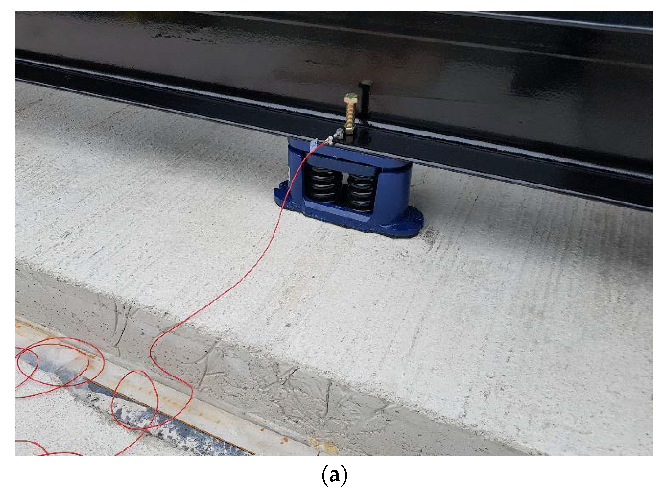
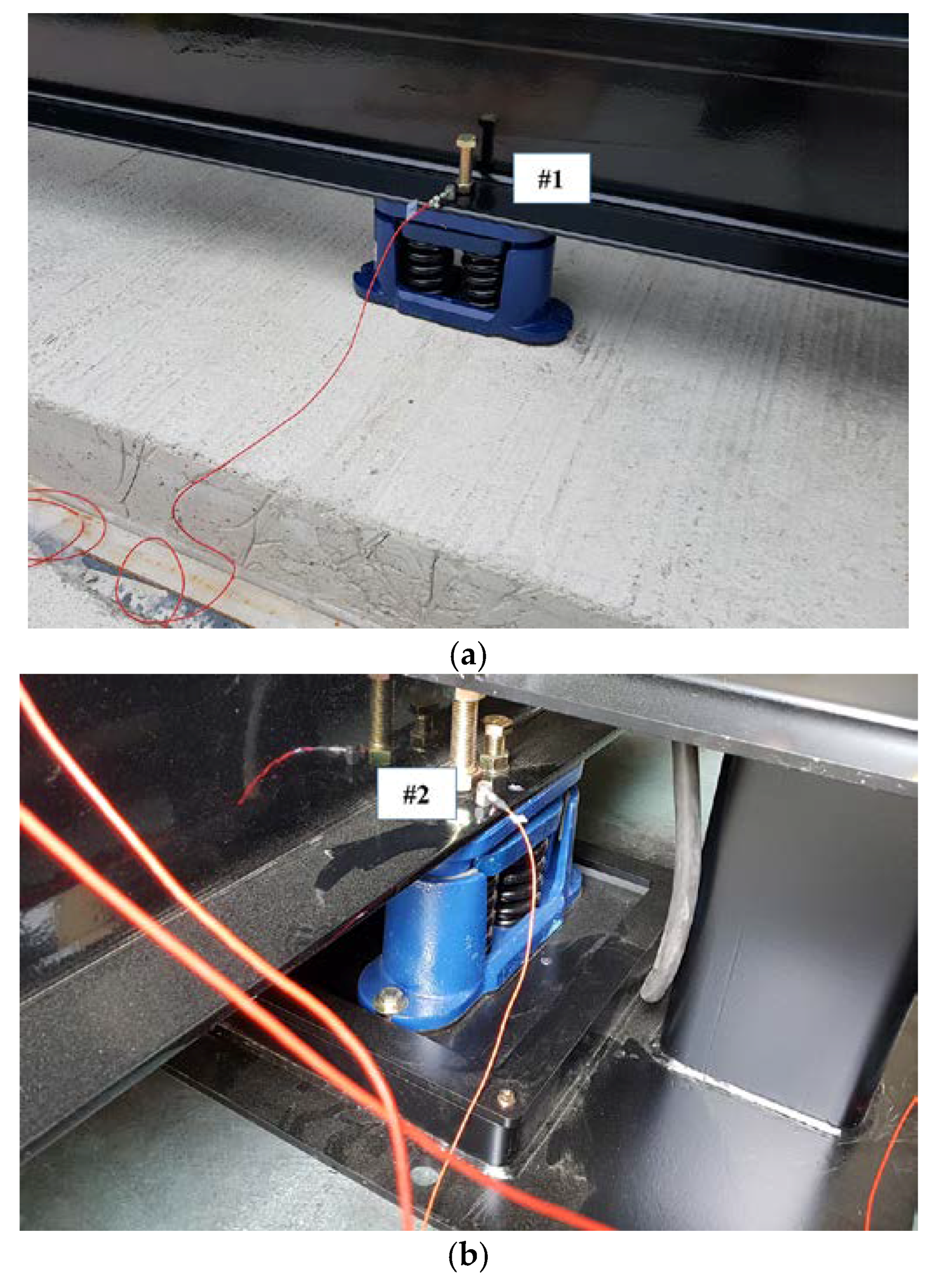
The simulation result was verified with the response motion at the power plant using two mount modules: one is the current mount and the other is the proposed one. The prototype mount module used as the proposed mount used the same spring component, and the damper panel located beneath the separator steel panel (see Figure 4) was the same number of stacked thin panel of damping material used at the current mount. The response motion at the power plant was measured using an accelerometer attached on the main frame of the power plant as illustrated in Figure 8; position #1 is responsible for the current mount, and position #2 is responsible for the proposed mount. Here, the specific location of the accelerometer was selected at the middle mount among the three mount modules (see Figure 2b and Figure 4) since that location is near to the mass center of the power plant.
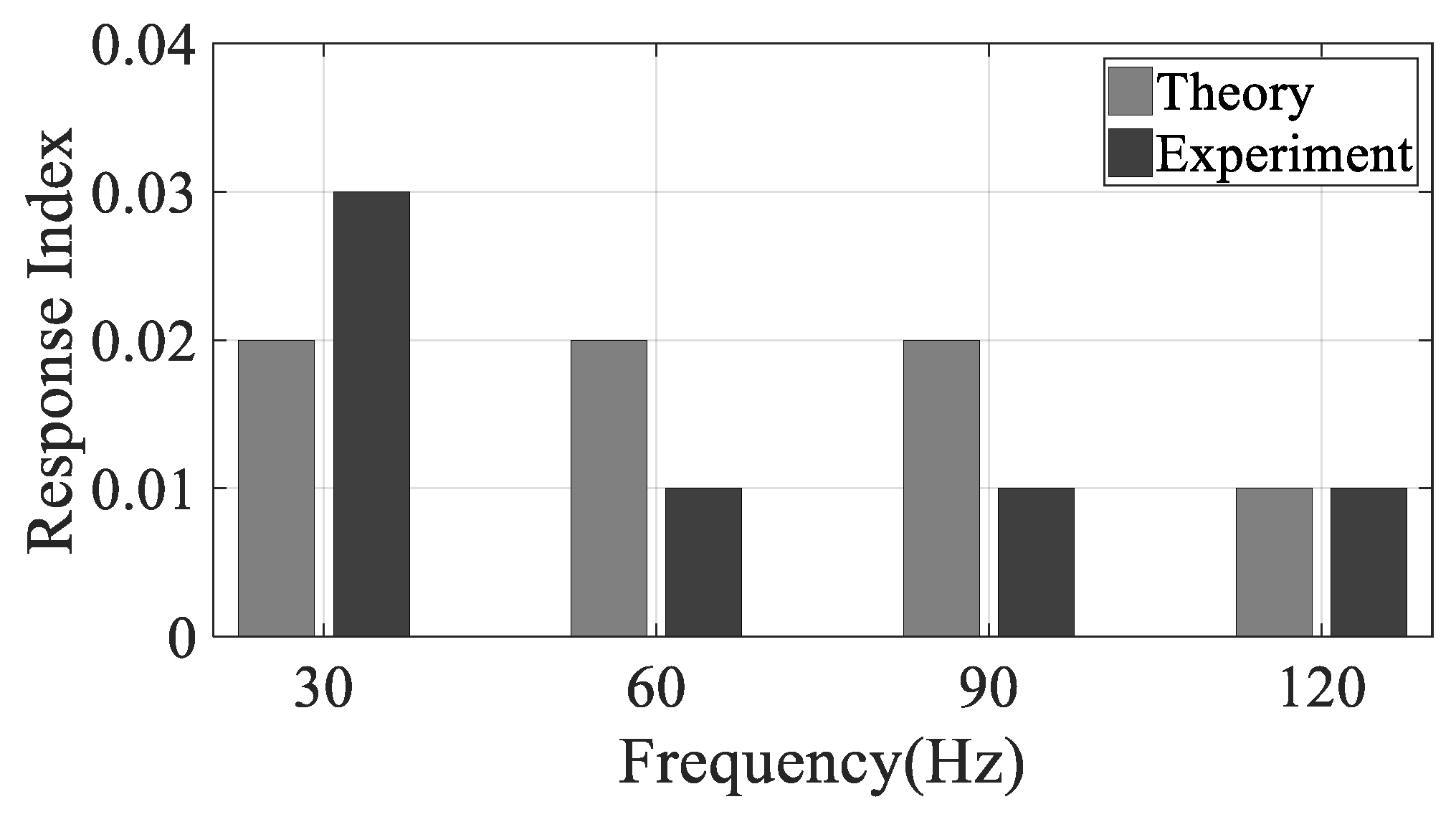
The test conditions of the electric power plant were assigned as the normal operation of the power plant so that acceleration motions were measured under 100% electric load and the rated engine speed, 1800 (rev/min). Since the major harmonic frequencies are solely dependent on the engine speed, and the electric load is concerned with the magnitude of excitation, only the 100% electric load case was selected in this study as the worst condition of excitation from the power plant. In other words, the capacity of the vibration isolator may be highlighted under the worst case of excitation. During operation, response data was collected at a sampling frequency of 1024 Hz using TEST.Lab (Siemens/Germany, Munich), and the response index was calculated from the measured responses. The comparison of response indices between theory and experiment are plotted in Figure 9.
The response index from the measured response data confirmed that the proposed mount module has superior capability of vibration isolation for all harmonic frequencies of interest with no base mass-block. The response index showed less than 0.03 at all harmonic frequencies of interest so that the response motion at the power plant with current mount promises to maintain the response level less than 3% with the current mount. That means the response motion at the electric power plant was efficiently controlled using the proposed mount module to solve the problem regarding the current module with regard to the maintenance cost as well as the difficulty of installation process. The discrepancy illustrated in Figure 9 may be caused by the unidentified dynamics in experimental approaches, such as nonlinear factors at the base mass-block, electric power plant, or mount module since the system models in Figure 3 and Figure 6 were extensively linearized with simple mechanical connectors. In addition, the selection of the damper component was concluded to be independent of the reaction motion at the electric power plant, but the issue of coefficients of damper component may not guarantee the same result if focused on the transmitted response motion at the basement floor.
5. Conclusions
The response motion at the electric power plant was the focus of this study, and the feasibility of the simplified mount module to minimize the reaction motion in the electric power plant was examined using two approaches; one was the theoretical calculation with the linearized mounted power plant model, and the other was the experimental validation with the field operation of the power plant under 100% electric load condition. In particular, the response index was introduced to derive the design criterion of the damper component in the proposed mount case, and the superior capacity of the proposed mount was proved with the theoretical approximation of the response index. Both results revealed that the proposed mount module had superior capability to control the reaction motion of the power plant less than 3% from the baseline with the current mount module. Since the proposed mount structure was simply designed with one spring component and one damper component, the installation process would become simple and the maintenance costs could be saved considerably because the use of the heavy base mass-block is eliminated. Therefore, relevant electric power plants can benefit by using the proposed mount module instead of the currently used mount structure to control the reaction motion at the power plant location.
Acknowledgments
This work was sponsored by National Research Foundation of Korea (Grant No. 2017R1D1A1B03034510).
Conflicts of Interest
The authors declare no conflict of interest.
References
- Gu, X.; Yu, Y.; Li, J.; Li, Y. Semi-active control of magnetorheological elastomer base isolation system utilizing learning-based inverse model. J. Sound Vib. 2017, 406, 346–362. [Google Scholar] [CrossRef]
- Santos, M.B.; Coelho, H.T.; Neto, F.P.L.; Mafhoud, J. Assessment of semi-active friction dampers. Mech. Syst. Signal Process. 2017, 94, 33–56. [Google Scholar] [CrossRef]
- Oh, H.U.; Choi, Y.J. Enhancement of pointing performance by semi-active variable damping isolator with strategies for attenuating chattering effects. Sens. Actuators A 2011, 165, 385–391. [Google Scholar] [CrossRef]
- Azadi, M.; Behzadipour, S.; Faulkner, G. Performance analysis of a semi-active mount made by a new variable stiffness spring. J. Sound Vib. 2011, 330, 2733–2746. [Google Scholar] [CrossRef]
- Zhou, P.; Du, J.; Lü, Z. Simultaneous topology optimization of supporting structure and loci of isolators in an active vibration isolation system. Comput. Struct. 2018, 194, 74–85. [Google Scholar] [CrossRef]
- Beijen, M.A.; Tjepkema, D.; Dijk, J. Two-sensor control in active vibration isolation using hard mounts. Control Eng. Pract. 2014, 26, 82–90. [Google Scholar] [CrossRef]
- Yang, X.L.; Wu, H.T.; Li, Y.; Chen, B. Dynamic isotropic design and decentralized active control of a six-axis vibration isolator via Stewart platform. Mech. Mach. Theory 2017, 117, 244–252. [Google Scholar] [CrossRef]
- Wang, Z.; Mak, C.M. Application of a movable active vibration control system on a floating raft. J. Sound Vib. 2018, 414, 233–244. [Google Scholar] [CrossRef]
- Li, Y.; He, L.; Shuai, C.G.; Wang, C.Y. Improved hybrid isolator with maglev actuator integrated in air spring for active-passive isolation of ship machinery vibration. J. Sound Vib. 2017, 407, 226–239. [Google Scholar] [CrossRef]
- Chi, W.; Cao, D.; Wang, D.; Tang, J.; Nie, Y.; Huang, W. Design and experimental study of a VCM-based stewart parallel mechanism used for active vibration isolation. Energies 2015, 8, 8001–8019. [Google Scholar] [CrossRef]
- Alujevic, N.; Cakmak, D.; Wolf, H.; Jokic, M. Passive and active vibration isolation system using inerter. J. Sound Vib. 2018, 418, 163–183. [Google Scholar] [CrossRef]
- Siami, A.; Karimi, H.R.; Cigada, A.; Zappa, E.; Sabbioni, E. Parameter optimization of an inerter-based isolator for passive vibration control of Michelangelo’s Rondanini Pieta. Mech. Syst. Signal Process. 2018, 98, 667–683. [Google Scholar] [CrossRef]
- Wu, Z.; Jing, X.; Sun, B.; Li, F. A 6DOF passive vibration isolator using X-shape supporting structures. J. Sound Vib. 2016, 380, 90–111. [Google Scholar] [CrossRef]
- Lee, J.; Okwudire, C.E. Reduction of vibrations of passively-isolated ultra-precision manufacturing machines using mode coupling. Precis. Eng. 2016, 43, 164–177. [Google Scholar] [CrossRef] [Green Version]
- Ribeiro, E.A.; Lopes, E.M.O.; Bavastri, C.A. A numerical and experimental study on optimal design of multi-DOF viscoelastic supports for passive vibration control in rotating machinery. J. Sound Vib. 2017, 411, 346–361. [Google Scholar] [CrossRef]
- Oh, H.U.; Lee, K.J.; Jo, M.S. A passive launch and on-orbit vibration isolation system for the spaceborne cryocooler. Aerosp. Sci. Technol. 2013, 28, 324–331. [Google Scholar] [CrossRef]
- Kim, C.J.; Kang, Y.J.; Lee, B.H.; Ahn, H.J. Design sensitivity analysis of a system under intact conditions using measured response data. J. Sound Vib. 2011, 331, 3213–3226. [Google Scholar] [CrossRef]
- Keulen, F.; Haftka, R.T.; Kim, N.H. Review of options for structural design sensitivity analysis. Part 1: Linear systems. Comput. Methods Appl. Mech. Eng. 2005, 194, 3213–3243. [Google Scholar] [CrossRef]
- Kim, C.J.; Lee, B.H.; Kang, Y.J.; Ahn, H.J. Accuracy enhancement of fatigue damage counting using design sensitivity analysis. J. Sound Vib. 2014, 333, 2971–2982. [Google Scholar] [CrossRef]
- Kim, C.J. Design sensitivity analysis of a Stockbridge damper to control resonance frequencies. J. Mech. Sci. Technol. 2017, 31, 4145–4150. [Google Scholar] [CrossRef]
- Yang, J.; Xiong, Y.P.; Xing, J.T. Vibration power flow and force transmission behavior of a nonlinear isolator mounted on a nonlinear base. Int. J. Mech. Sci. 2016, 115–116, 238–252. [Google Scholar] [CrossRef]
- Hu, Z.; Zheng, G. A combined dynamic analysis method for geometrically nonlinear vibration isolation with elastic rings. Mech. Syst. Signal Process. 2016, 76–77, 634–648. [Google Scholar] [CrossRef]
- Yan, L.; Gong, X. Experimental study of vibration isolation characteristics of a geometric anti-spring isolator. Appl. Sci. 2017, 7, 711. [Google Scholar] [CrossRef]
- Lee, G.S.; Lee, M.Y.; Kim, K.H.; Kim, C.J. Selection of damping coefficient of simplified mount module to control transmissibility of environmental response under no base mass-block. Int. J. Eng. Technol. 2018, 7, 151–155. [Google Scholar]
- Rao, S.S. Mechanical Vibration, 5th ed.; Pearson: Singapore, 2011. [Google Scholar]
- Inman, D.J. Engineering Vibration, 4th ed.; Pearson: Singapore, 2013. [Google Scholar]
Figure 1.
Electric power plant with 750 KW capacity.

Figure 2.
Passive-type current mount module for electric power plant. (a) Side view; (b) Mount diagram.
Figure 2.
Passive-type current mount module for electric power plant. (a) Side view; (b) Mount diagram.


Figure 3.
Equivalent system model of electric power plant supported by current mount module.
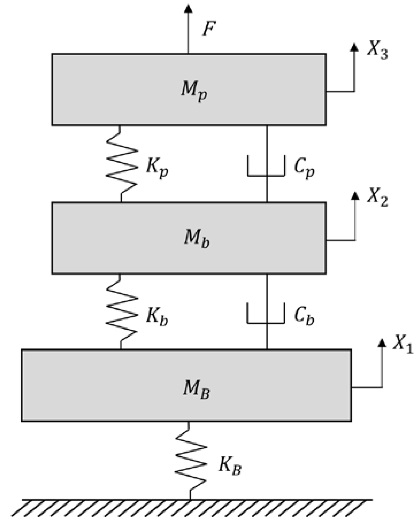
Figure 4.
Mount diagram of proposed mount module.

Figure 5.
Proto-type of simplified mount module. (Korean label denotes manufacturer of spring component, YJ Industrial Co., Ltd./South Korea, Gyeonggi-do).
Figure 5.
Proto-type of simplified mount module. (Korean label denotes manufacturer of spring component, YJ Industrial Co., Ltd./South Korea, Gyeonggi-do).

Figure 6.
Equivalent system model of electric power plant supported by proposed mount module.

Figure 7.
Comparison of magnitude of frequency response functions.
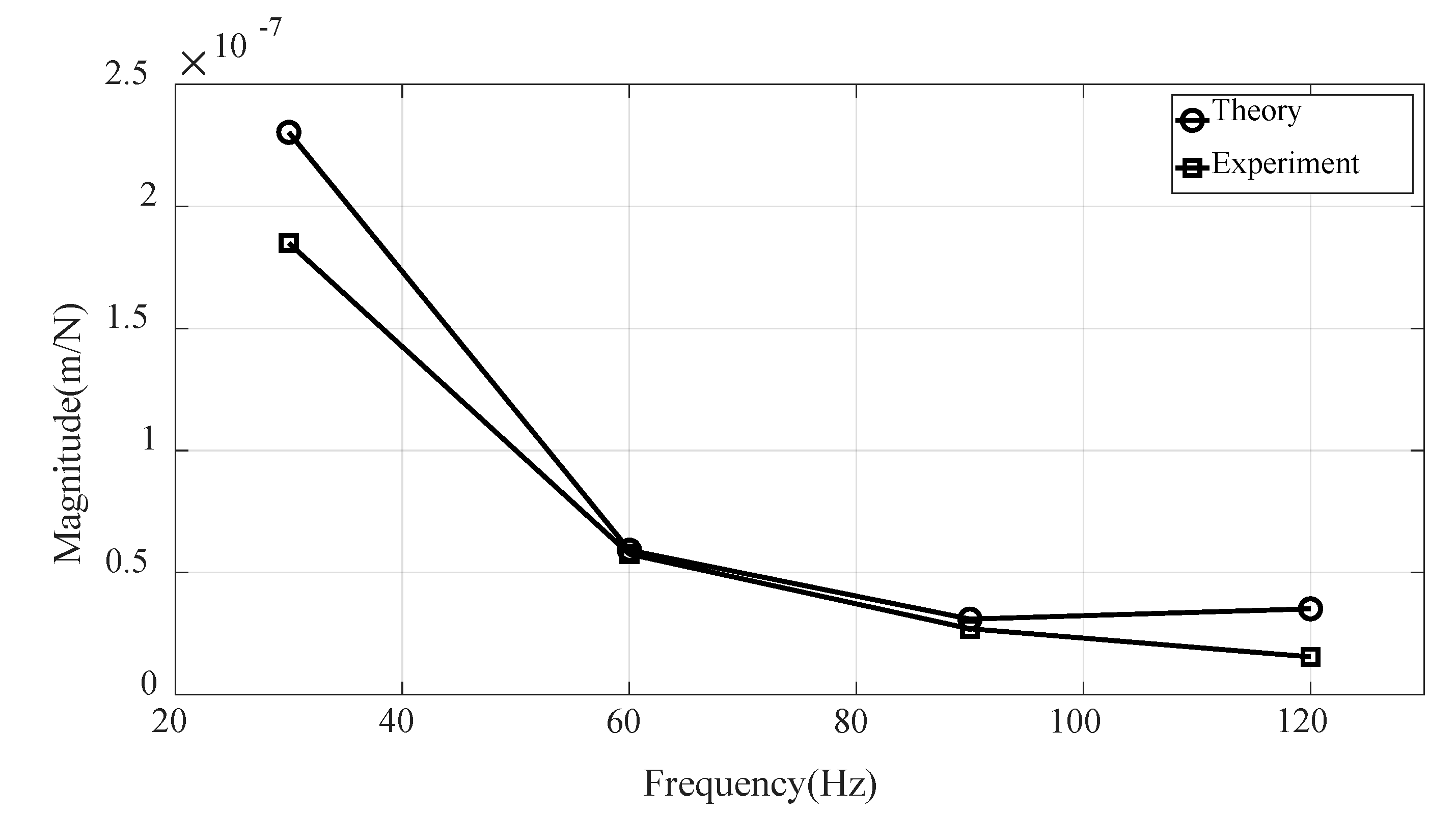
Figure 8.
Configuration of attached sensor locations at electric power plant: (a) current mount (#1) and (b) proposed mount (#2).
Figure 8.
Configuration of attached sensor locations at electric power plant: (a) current mount (#1) and (b) proposed mount (#2).

Figure 9.
Comparison of response index at the elect power plant location.


Table 1.
Specification of electric power plant.
| Item | Detail (Dimension) |
|---|---|
| Dimension (L/W/H) | 3390/1397/2180 (mm) |
| Mass of power plant | 6070 (kg) |
| Mass of base mass-block | 6900 (kg) |
Table 2.
Mechanical properties for main harmonic spectrum.
| Component | Coefficient | |||
|---|---|---|---|---|
| 30 (Hz) | 60 (Hz) | 90 (Hz) | 120 (Hz) | |
| Spring | 175.0 (kN/m) | 207.5 (kN/m) | 313.5 (kN/m) | 733.2 (kN/m) |
| Damper | 62.7 (Ns/m) | 36.0 (Ns/m) | 30.7 (Ns/m) | 26.3 (Ns/m) |
Table 3.
Variables used in equivalent electric power plant.
| Variable | Value |
|---|---|
| (kg) | 6070 (kg) |
| (kg) | 6900 (kg) |
| (kg) | |
| (kN/m) | 1050 (30 Hz), 1245 (60 Hz), 1881 (90 Hz), 4399 (120 Hz) |
| (kN/m) | |
| (kN/m) | |
| (Ns/m) | 376 (30 Hz), 216 (60 Hz), 184 (90 Hz), 158 (120 Hz) |
| (Ns/m) |
Table 4.
Theoretical calculation result regarding response index.
| Term | Result | |||
|---|---|---|---|---|
| 30 (Hz) | 60 (Hz) | 90 (Hz) | 120 (Hz) | |
| (kg/s2) | 4.3 × 10⁶ | 1.7 × 10⁷ | 3.2 × 10⁶ | 2.8 × 10⁶ |
| (kg/s2) | 2.3 × 10⁸ | 8.6 × 10⁸ | 1.9 × 10⁹ | 3.5 × 10⁹ |
| 0.02 | 0.02 | 0.02 | 0.01 | |
Table 5.
Theoretical response index from frequency response functions for different damping coefficients ( = 43,990 (kN/m)).
Table 5.
Theoretical response index from frequency response functions for different damping coefficients ( = 43,990 (kN/m)).
| Response Index | ||||
|---|---|---|---|---|
| 30 (Hz) | 60 (Hz) | 90 (Hz) | 120 (Hz) | |
| 1 (Ns/m) | 0.02 | 0.02 | 0.02 | 0.01 |
| 103 (Ns/m) | 0.02 | 0.02 | 0.02 | 0.01 |
| 106 (Ns/m) | 0.01 | 0.02 | 0.02 | 0.01 |
© 2018 by the author. Licensee MDPI, Basel, Switzerland. This article is an open access article distributed under the terms and conditions of the Creative Commons Attribution (CC BY) license (http://creativecommons.org/licenses/by/4.0/).
Share and Cite
MDPI and ACS Style
Kim, C.-J. Design Criterion of Damper Component of Passive-Type Mount Module without Using Base Mass-Block. Energies 2018, 11, 1548. https://doi.org/10.3390/en11061548
AMA Style
Kim C-J. Design Criterion of Damper Component of Passive-Type Mount Module without Using Base Mass-Block. Energies. 2018; 11(6):1548. https://doi.org/10.3390/en11061548
Chicago/Turabian StyleKim, Chan-Jung. 2018. "Design Criterion of Damper Component of Passive-Type Mount Module without Using Base Mass-Block" Energies 11, no. 6: 1548. https://doi.org/10.3390/en11061548
Note that from the first issue of 2016, this journal uses article numbers instead of page numbers. See further details here.