Analysis and Optimization of the Electromagnetic Performance of a Novel Stator Modular Ring Drive Thruster Motor


1
School of Marine Science and Technology, Northwestern Polytechnical University, Xi’an 710072, China
2
Key Laboratory for Unmanned Underwater Vehicle, Northwestern Polytechnical University, Xi’an 710072, China
*
Author to whom correspondence should be addressed.
Energies 2018, 11(6), 1598; https://doi.org/10.3390/en11061598
Submission received: 8 May 2018
/
Revised: 7 June 2018
/
Accepted: 13 June 2018
/
Published: 19 June 2018
Abstract
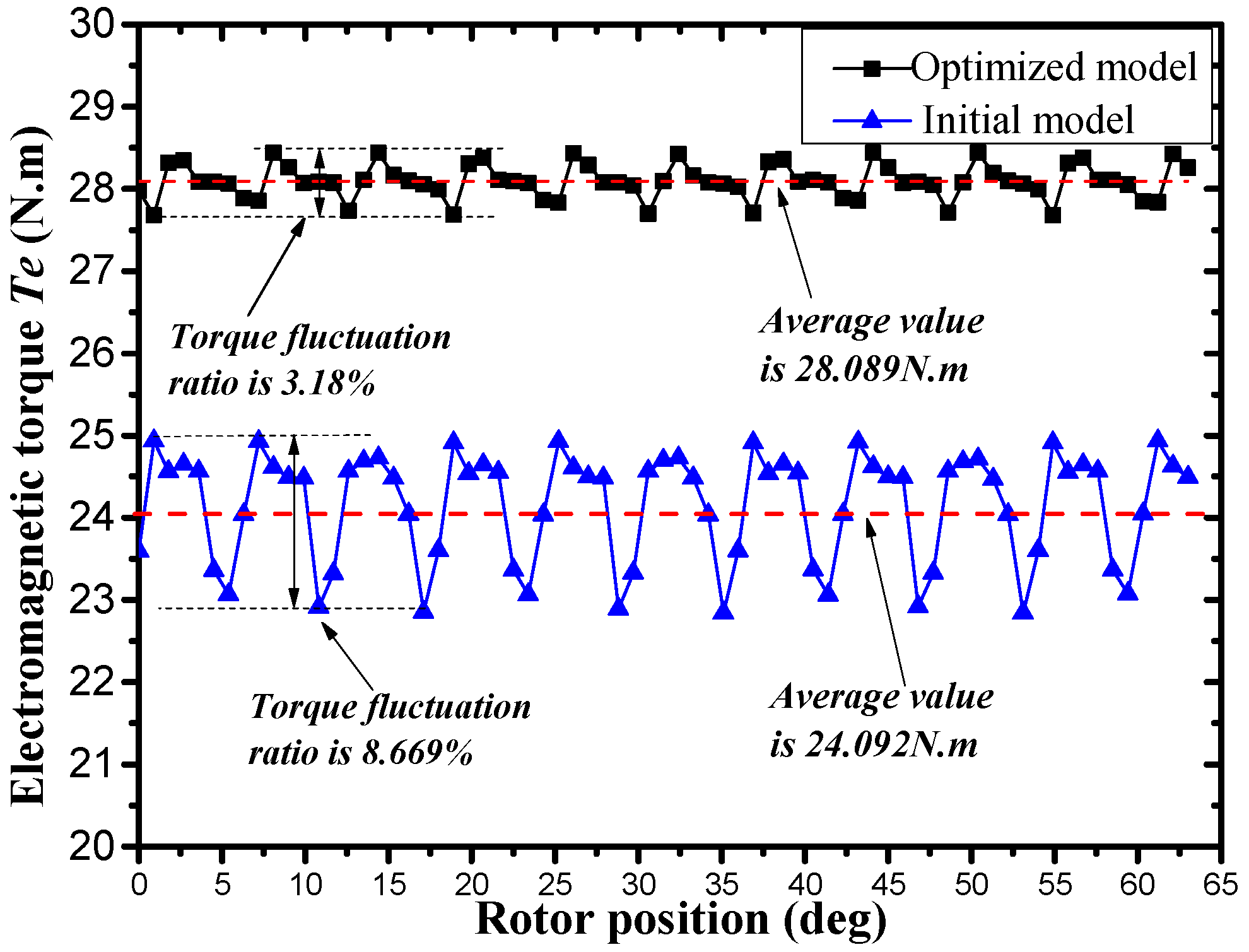
:A rim driven thruster (RDT) is an integrated deep-sea motor thruster that has been widely studied. In order to improve the performance of RDT, a novel RDT motor with a modular stator is proposed in this paper. The electromagnetic performance of the new RDT motor is analyzed by the finite element method (FEM). The influence of structure parameters on the electromagnetic performance of the new RDT motor are analyzed in detail. It is shown that the effect of additional tooth width and pole arc coefficient on the electromagnetic performance of the stator modular RDT motor is significant. To obtain the optimal design with a maximum average electromagnetic torque and minimum torque fluctuation ratio, a multi-objective optimization design method combining the non-dominated sorting genetic algorithm II (NSGA-II), Kriging method and FEM is presented in this paper. A set of Pareto optimal solutions is obtained, and the optimal design point is selected from the Pareto fronts. Compared with the initial design, the average electromagnetic torque of the optimized model is improved by 16.591% and the fluctuation ratio is reduced to 3.18%.
1. Introduction
The ocean area accounts for over two-thirds of the earth’s surface, most of which are deep sea areas that still remain to be explored. With the rapid development of marine technology, interest in deep sea exploration is increasing both in the scientific and business communities [1]. Motor thruster is one of the core components of deep-sea exploration equipment, and affects their overall performance directly.
The deep-sea environment is characterized by the total absence of sunlight and high hydrostatic pressure [2]. The requirements for the motor thruster are as follows:
- (1)
- High pressure resistance: The deep-sea motor thruster must be able to work under deep sea water pressure.
- (2)
- Corrosion resistance: The part of the motor thruster that is in direct contact with seawater must have seawater corrosion resistance.
- (3)
- High power density: Increasing the power density can effectively reduce the weight of the motor thruster.
- (4)
- High efficiency: Deep sea exploration equipment has limited energy which is hard to replenish. Increasing the propulsion efficiency means further voyage and higher working performance.
- (5)
- Low noise: Propeller noise may affect the acquisition and transmission of signals.
- (6)
- Fault-tolerant performance: Deep-sea detection equipment requires the motor thruster to be able to operate reliably and continuously. Therefore, it is required to have a high fault-tolerant performance.
The initial motor thruster for the deep-sea is developed from ordinary shallow water thrusters, such as podded drive propulsion. It uses complex mechanical seals or magnetic coupling seals to replace simple sealing structures, while increasing the wall thickness of the motor housing or using oil filled pressure balance to withstand deep-sea pressure [3,4]. This structure results in the increased weight and low power density of the deep-sea motor thruster.
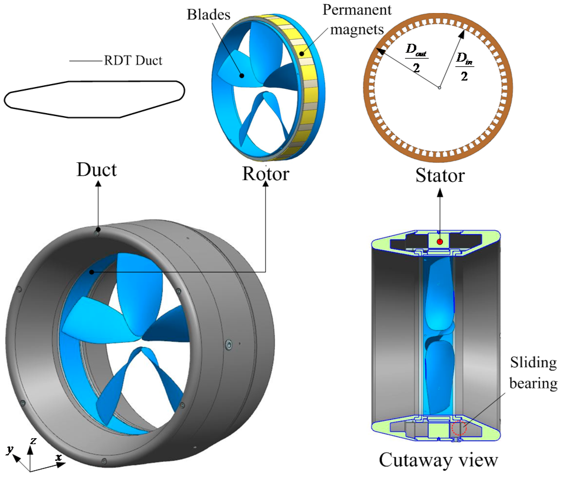
In order to simplify the structure of the deep-sea thruster and improve its overall performance, the integrated motor propulsor named the rim driven thruster (RDT) has been widely studied in the past 20 years (as shown in Figure 1) [5,6]. The permanent magnets are surface-mounted in a rim around the tips of the blades and the motor stator is mounted in the duct. The RDT shows many advantages over conventional propulsion system, such a as more simple structure due to the elimination of the gear and shafts, lower noise and vibration due to the less tip vortices, space savings and more flexible installation due to the compact design [7,8,9]. The open water efficiency of the propeller of RDT is also higher than that of a podded drive propulsion [10].
There are many factors that affect the overall performance of the RDT, including the output characteristics of the motor, the matching of the motor and the propeller, the shape of the duct and the structure of the bearing, among which the motor is the most important and influential factor [8]. Research on this type of motor focuses on the optimization of electromagnetic performance, motor sealing, anti-corrosion, cooling, control system, weight and thickness, and cost [8,11]. The structure of the RDT determines that the permanent magnet motor used in RDT has the characteristics of a large inner diameter and a short axial length, and it is required to reduce the thickness of the duct to reduce its impact on the hydrodynamic performance of the thruster [12]. Because permanent magnet (PM) motors have the characteristics of a simple structure, large air gap, small radial thickness, and large power density, most researchers prefer to use PM motors in their RDT designs. In 2004, a 100 kW PM motor with 22 magnetic poles and a two-layer fractional winding was designed [13]. The axial flux PM motor had also been considered in RDT, and has better performance in terms of compactness and thermal behavior [14]. In the paper [11], an integrated magnetically slotless PM Brushless motor with a two-segment Halbach array was developed to meet the requirements of compact size and low noise.
Nevertheless, all the previous PM motors in RDT have a whole piece of stator, which have the characteristics of high processing costs and poor fault-tolerance. From the viewpoint of reducing the cost and improving the performance of RDT, a novel RDT motor with a modular stator is proposed in this paper. The average electromagnetic torque and torque fluctuation ratio are taken as the optimization objectives, since they are very important for the RDT motor.
The multi-objective optimization design of motor is a nonlinear problem. The most popular method is performed using FEM coupled with surrogate models and optimization algorithms [15]. However, the optimization algorithms are not very efficient, especially for the optimal design of new-structure motors [16]. Another global optimization technique is the Taguchi method, which is developed based on orthogonal experimental design and statistical analysis [17]. The Taguchi method can significantly reduce the computational time, but the suboptimal solution is often obtained [18,19]. For the novel RDT motor proposed in this paper, the design space, cost and computational time of the multi-objective optimization design must be reduced. A hybrid method combining NSGA-II, Kriging method and FEM is described in this paper. The structure and electromagnetic performance of new RDT motor will first be studied in detail. Then, the impact of the RDT design parameters including additional tooth height, additional tooth width, slot opening width, and pole arc coefficient on the electromagnetic performance of the new RDT motor are investigated by using FEM. Through the above analysis, the additional tooth width and the polar arc coefficient are selected as the main influence factors. 56 samples are identified and resolved by orthogonal design and their electromagnetic performances are studied by FEM. Based on the Kriging method, two surrogate models are established. Finally, the NSGA-II algorithm is applied to complete the multi-objective optimization process and get the optimum design point of the new RDT motor.
2. Geometry Configuration
For RDT, its input power Pin and output mechanical power Pout could be expressed as:
where, is the effective value of the input voltage, is the effective value of the input current, T is the thrust of propeller, and Va is the freestream fluid velocity. So, the overall efficiency of RDT can be calculated by equation, as below:
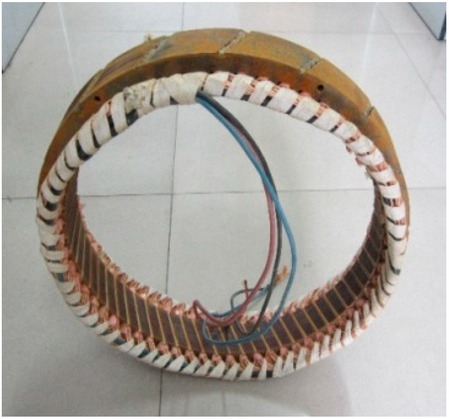
In recent years, there have been many prototype processing and experimental studies on RDT. A traditional RDT prototype that has been processed and tested by our team is shown in Figure 2a, and its overall efficiency curve obtained from hydrodynamic experiments is shown in Figure 2b. The advance ratio (J) means the ratio of the freestream fluid speed to the propeller tip speed, i.e., J is defined as below [20]:
where n is the propeller’s rotational speed in rotations per second, D is the propeller’s diameter. It can be seen that the maximum overall efficiency of the RDT is only 50.9%. Therefore, it is necessary to improve the design of RDT, including the structure of the motor, the propeller, the duct and the connection mechanism, etc.
If the efficiency of the motor is defined as , the efficiency of the propeller with the duct is defined as , and the other mechanical loss is denoted by a coefficient kL. Then, the overall efficiency of RDT could also be expressed as:
The efficiency of the motor and propeller for RDT could be expressed as below:
where Te is the electromagnetic torque, KT is the total thrust coefficient, and KQ is the total torque coefficient. Since the propeller of RDT has a duct, KT is the sum of the thrust coefficient of the propeller and duct, while KQ is the sum of the torque coefficient of propeller and duct, as below [21,22]:
where KTB is the thrust coefficient of propeller, KQB is the torque coefficient of propeller, KTN is the thrust coefficient of duct, KQV is the torque coefficient of duct, TB is the thrust of propeller, QB is the torque of propeller, TN is the thrust of duct, and QN is the torque of duct. Propeller torque is provided by the RDT motor. The electromagnetic torque and the propeller torque of the RDT are equal while ignoring the loss of the torque transmission process. Using the virtual work method, the expression of the electromagnetic torque Te of RDT motor is as follows [23,24]:
where Wm is the magnetic field energy, is the rotor position angle, and BPr and BWr are radial components of the main magnetic field and armature winding magnetic field respectively.
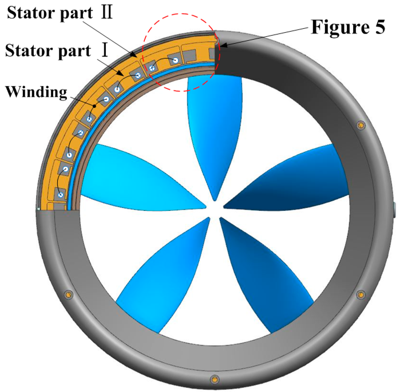
This paper focus on the improvement of motor performance. Figure 3 shows the stator armature of the traditional RDT. It adopts distributed windings with skew-slot, which have the disadvantages of long end windings, large copper loss, low fault-tolerant capability, high processing costs and so on. The structure of the new RDT proposed in this paper is shown in Figure 4. Its stator is composed of stator part I and stator part II, the stator part I is the winding tooth segment, and the stator part II is the additional tooth segment. The additional tooth segment can help to fix the winding teeth, and achieves isolation between windings. Obviously, this structure reduces the difficulty of stator processing, significantly decreases the length of the end winding, and at the same time, it can realize the physical, thermal and electromagnetic isolation of each phase winding, and improves fault tolerance capability.
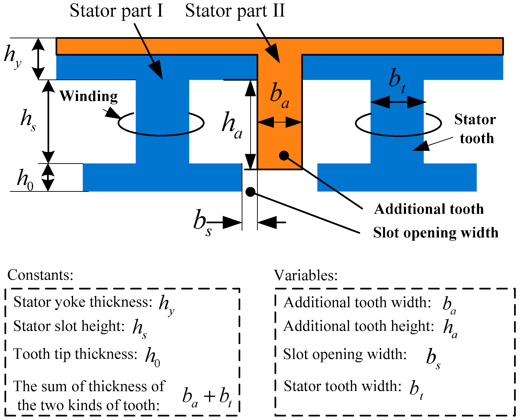
The structure parameters of the new RDT stator is shown in Figure 5. ba and ha are the width and height of the additional tooth respectively, bs is the slot opening width. When changing the height and width of the additional tooth, the effective area of the slot remains unchanged, that is to say, the thickness and height of the winding are not changed without changing the inner and outer diameters of the rotor and the thickness of the stator yoke. The stator modular RDT motor is initially designed, and some parameters of the initial stator modular RDT motor and the traditional RDT motor are given in Table 1.
Numerical simulation is a precise and high-efficient investigation approach of RDT motors. Ignoring the end-effect and coupling the electromagnetic field with the circuit, the electromagnetic performance of the RDT motor can be accurately predicted by two-dimensional (2D) FEM. All of the numerical simulations are carried out using the electromagnetic field analysis software Infolytica/MagNet (Mentor Graphics Corporation, Wilsonville, OR, USA). The computer used for the calculation is a Lenovo-P320 workstation (Shangdi Information Industry Base, Beijing, China) dual CPU, 16 GB of memory, 2TB storage and windows 7 64-bit operating system.(Microsoft Corporation, Redmond, WA, USA) The calculation time for each RDT motor sample is approximately 2 h.
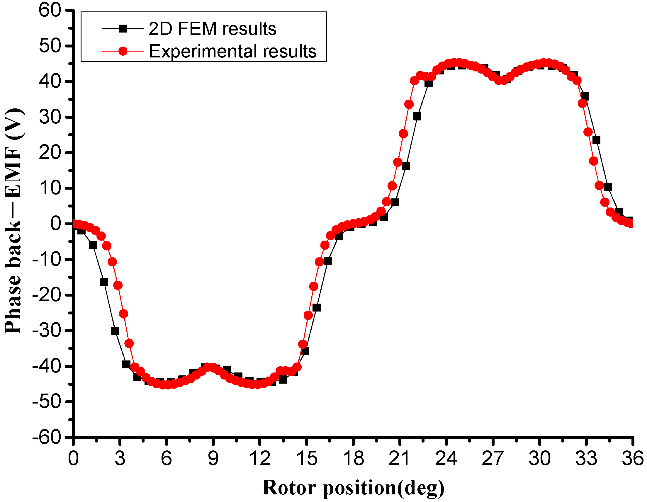
Figure 6 shows the phase back-EMF of the traditional RDT motor that obtained by 2D FEM and experiment. It can be seen that the phase back-FEM waveform of the 2D FEM results are in good agreement with the experimental results. That means the numerical simulation using Infolytica/MagNet is acceptable.
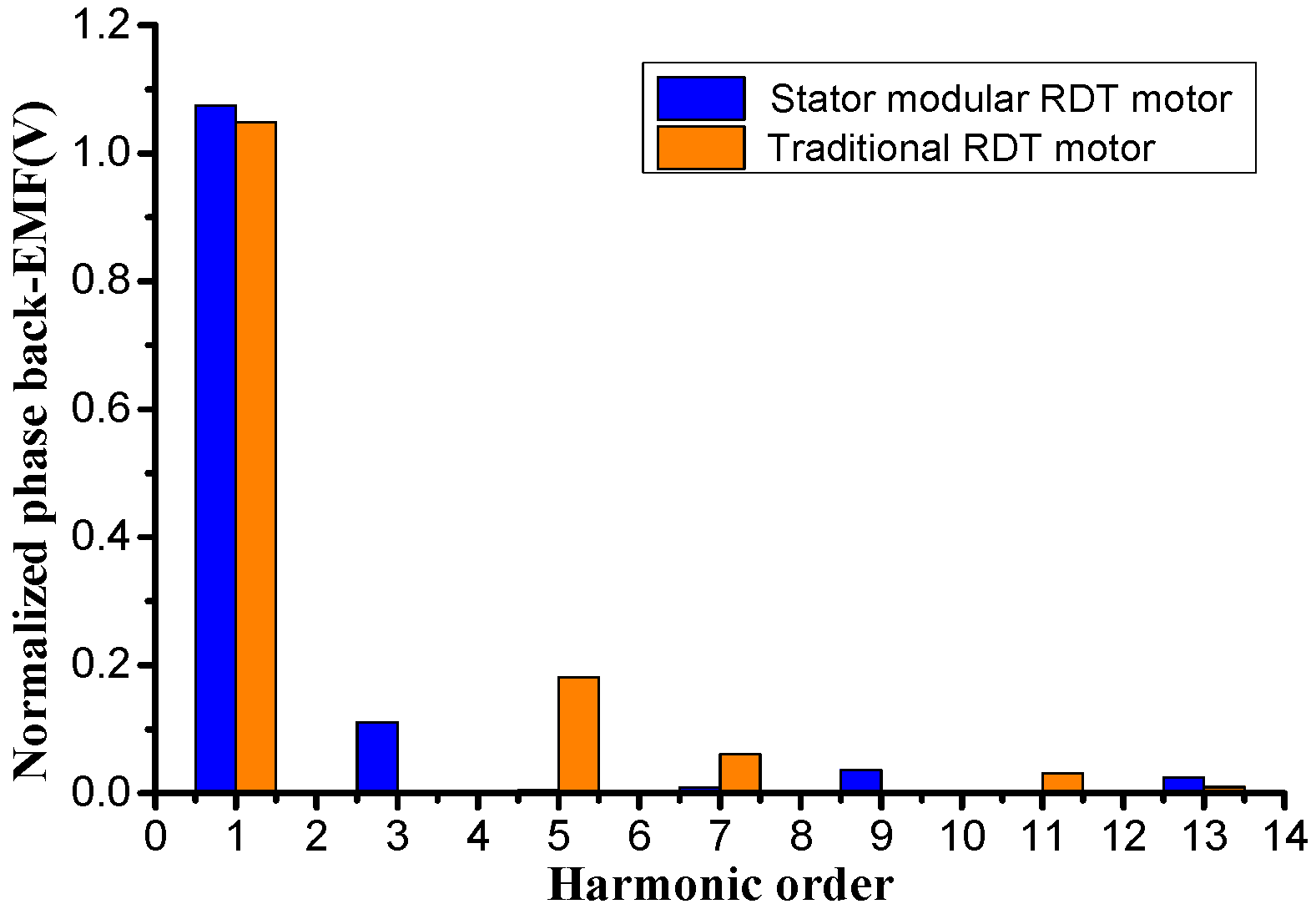
The static magnetic field distribution of two motors is shown in Figure 7. It can be seen that there is no obvious magnetic saturation in the case of keeping the stator yoke thickness constant. However, compared to the traditional motor, stator modular RDT motor motors has obvious zigzag leakage fluxes at the top of the tooth, and the zigzag leakage coefficient is shown in Table 2. Figure 8 is the normalized phase back-EMF of two RDT motors. Compared with the traditional RDT motor, the stator modular RDT motor is more suitable for sine wave drive. Harmonic analysis of the back-EMF (as shown in Figure 9) shows that the stator modular RDT motor increases the fundamental and 3rd harmonic, and basically eliminates the 5th harmonic.
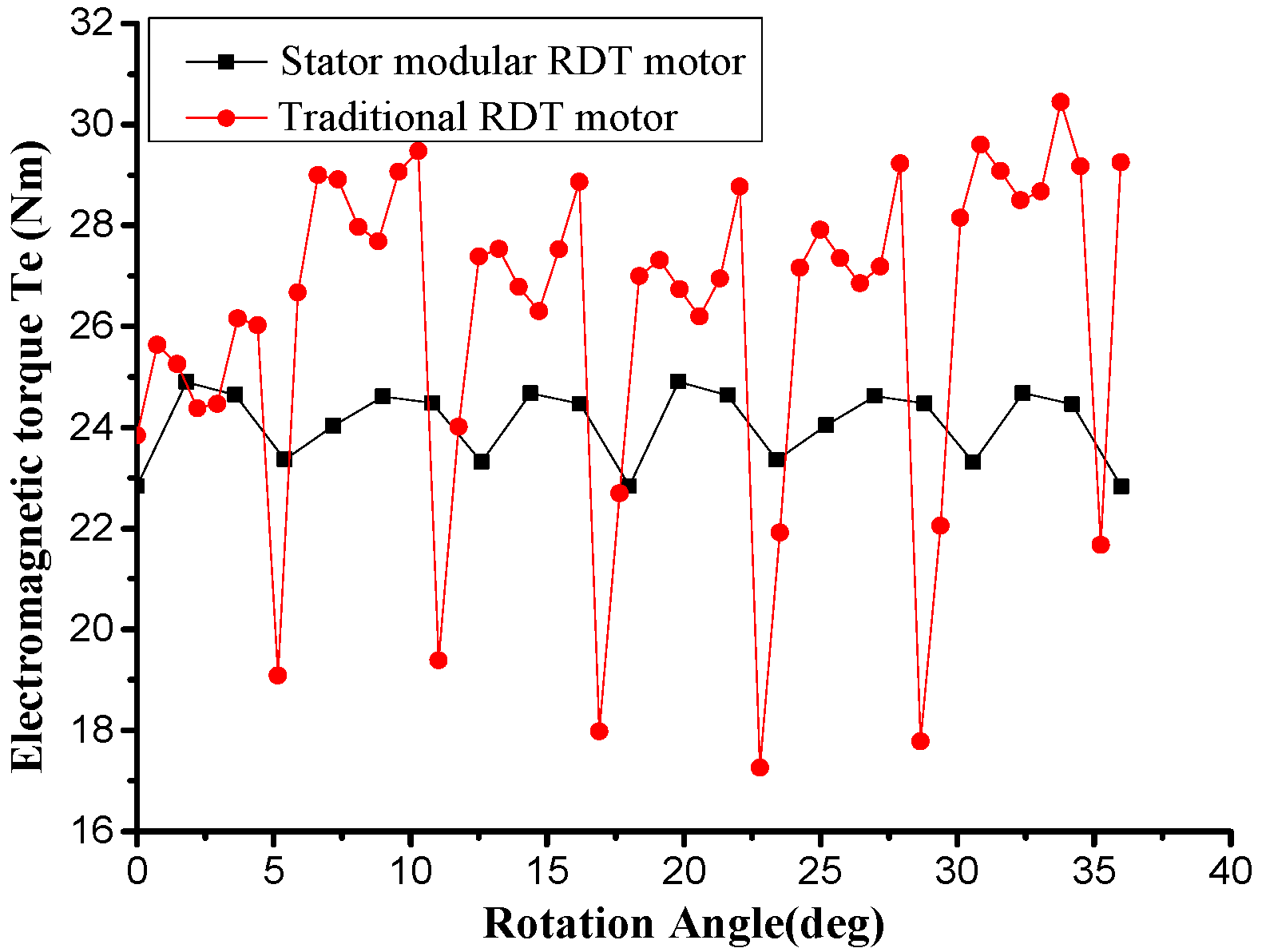
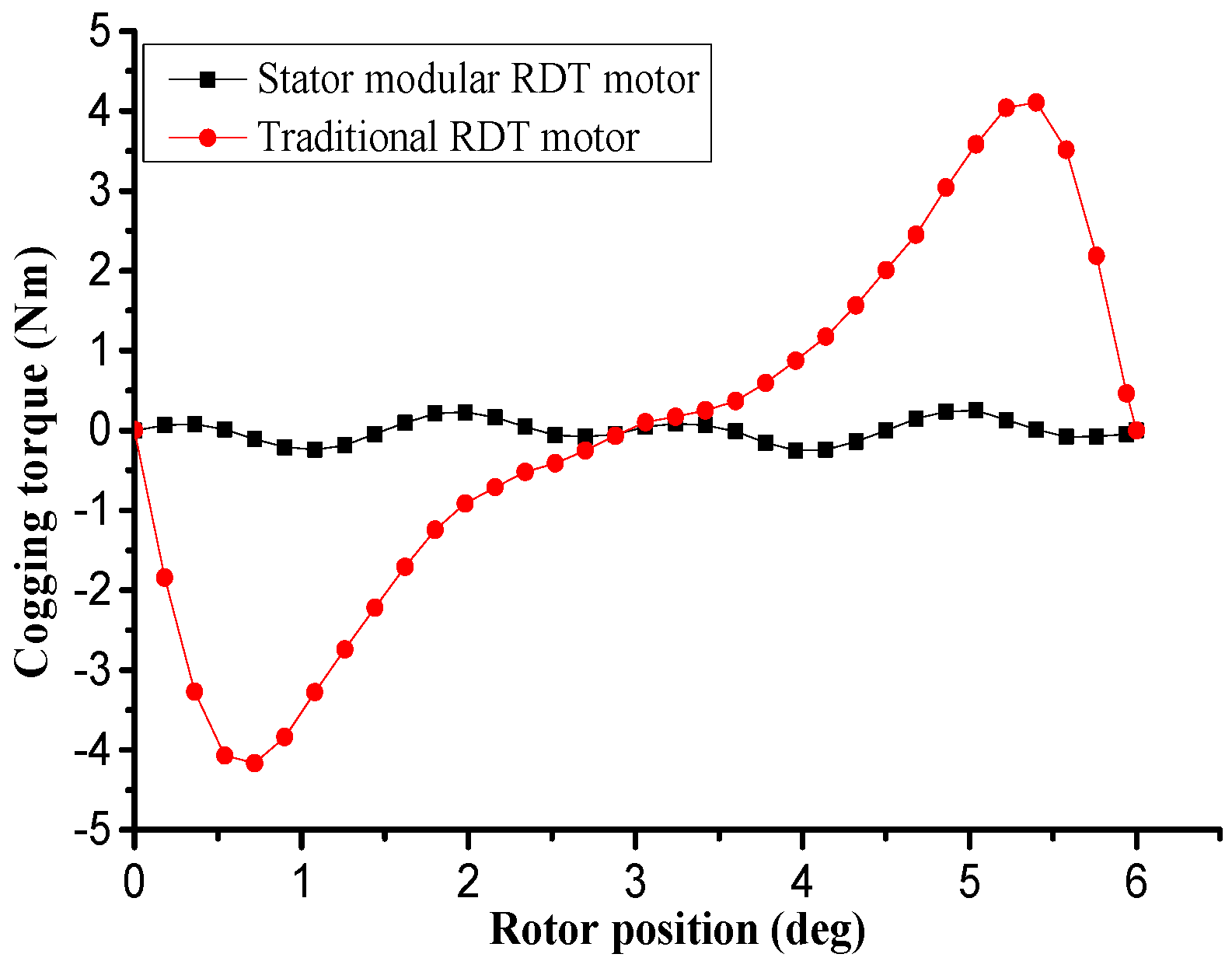
For RDT, output torque characteristics of its motor directly affect the propeller’s efficiency and noise performance. The electromagnetic torque of two RDT motors is shown in Figure 10. Obviously, the electromagnetic torque of stator modular RDT motor is much smaller than that of the traditional RDT motor. Figure 11 shows the cogging torque of two RDT motors. The new stator modular RDT motor basically eliminates the cogging torque without using the skew-slot. Overall, the novel RDT motor can effectively decrease the output torque fluctuations and reduce the processing difficulty, so it is suitable for underwater propulsion.
3. Influence of Structural Parameters on the New RDT Motor
The stator modular RDT motor proposed in this paper uses fractional-slot concentrated windings and has a unique additional tooth structure. The design optimization of a PM motor is a high-dimensional multi-objective problem because of the great number of design parameters, objectives, and constraints [16,25]. In actual production, the manufacturing tolerances also need to be taken into account [26]. This paper focuses on the influence of the four design parameters on the electromagnetic performance of the RDT motor, and neglects the manufacturing tolerances.
The influence of these structure parameters, including additional tooth height, additional tooth width, slot opening width, and pole arc coefficient on the electromagnetic performance of the new RDT motor are analyzed in detail by 2D FEM.
3.1. Influence of the Slot Opening Width
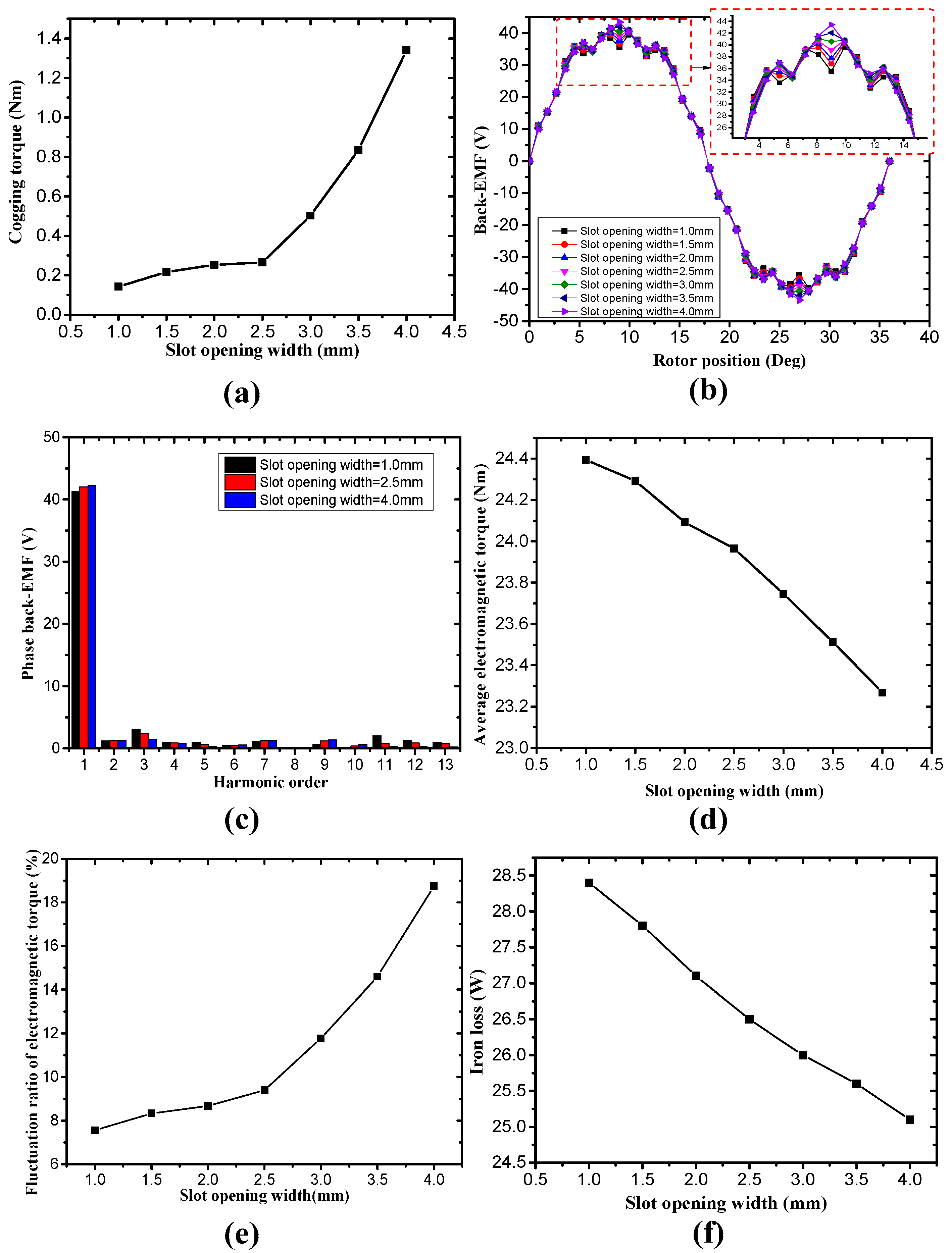
The slot opening width bs is varied from 1 mm to 4.0 mm with a 0.5 mm interval, and the other design parameters remained unchanged. 7 models are established and their electromagnetic performances are obtained by the finite element method. Figure 11 shows the influence of the slot opening on the electromagnetic performance of the stator modular RDT motor. The peak value of cogging torque of the new RDT motor with a different slot opening width is predicted and shown in Figure 12a. When the slot opening width is quite small, the cogging torque slightly changes. However, when the slot opening width is greater, more flux leakage will go through the additional tooth, and the cogging torque increases rapidly. Figure 12b,c are the back-EMF and the harmonic distribution for the new RDT motor with different slot opening width. Figure 12d,e are the average electromagnetic torque and the fluctuation ratio of the electromagnetic torque.
With the increase of the slot opening width, the average electromagnetic torque decreases, and the fluctuation ratio increases. The main reason for the decrease of the average electromagnetic torque is that with the increase of the slot opening width, the amplitude of the 3rd and 11th harmonics are greatly reduced, which exceeds the influence of the amplitudes of the 1st and the 9th harmonics on the electromagnetic torque. It can also be seen from the figure that the variation trend of the fluctuation ratio of electromagnetic torque is similar to that of the cogging torque. This is because the change of the electromagnetic torque is codetermined by the cogging torque and the harmonic distribution of back-EMF. Figure 12f is the curve of the stator iron loss. The stator iron loss slightly decreases with the increase of the slot opening width. This is due to the increase of the slot opening leading to the reduction of the tooth tip. For the new RDT motor, reduce tooth tip means that the magnetic field oversaturated area becomes smaller.
The influence of the slot opening width on electromagnetic torque and torque fluctuation is monotonous, that is, as the notch width increases, the electromagnetic torque decreases, while the torque ripple increases. So, the slot opening width of the new RDT motor should be 1 mm.
3.2. Influence of the Additional Tooth Height
The additional tooth height ha changes from 10 mm to 14 mm with a 1 mm interval. Figure 13 shows the influence of the additional tooth height on the electromagnetic performance of the stator modular RDT motor. It can be seen from the figure that the influence of the additional tooth height on the back-EMF and the average electromagnetic torque is very weak. However, with the increase in the height of the additional tooth, the cogging torque and fluctuation ratio of electromagnetic torque are significantly reduced, and the iron loss is also slightly reduced. Therefore, the additional tooth height should be the maximum value, i.e., ha = 14 mm.
3.3. Influence of the Additional Tooth Width
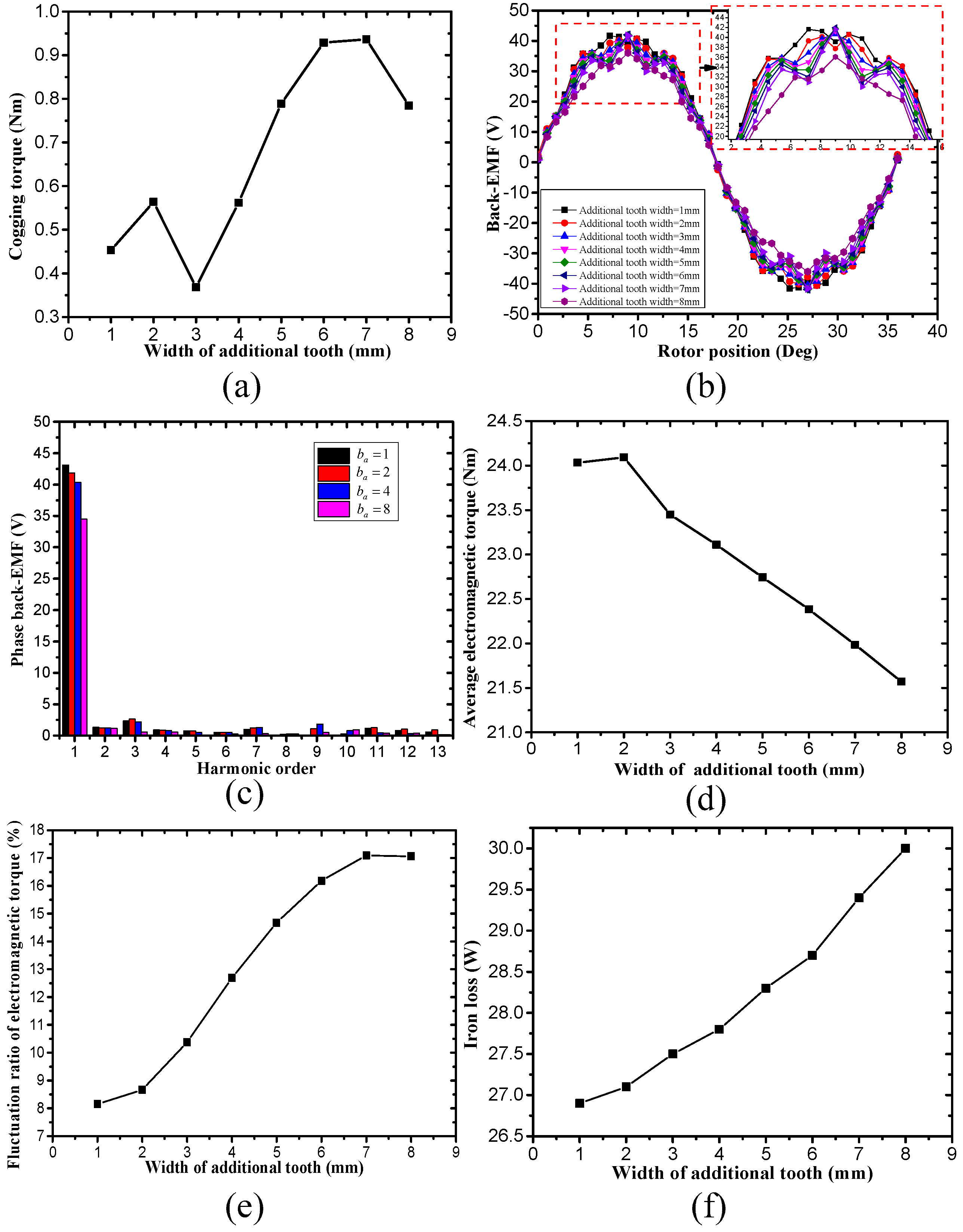
The change of the additional tooth width (ba) changes the position of the slot opening as well as affecting the winding coefficient. As shown in Figure 14, the additional tooth width ba changes from 1 mm to 8 mm with a 1 mm interval, with the increase of the additional tooth width, the average electromagnetic torque increases first and then decreases, and the fluctuation ratio of the electromagnetic torque increases continuously. The effect of additional tooth width on the average electromagnetic torque and the fluctuation ratio is very significant. It also can be seen from the figure that the iron loss continues to increase with the increase of the additional tooth width.
3.4. Influence of the Pole Arc Coefficient
The pole arc coefficient directly affects the air gap flux density and the stator magnetic field, thereby affecting the electromagnetic performance of the stator modular RDT motor. As can be seen from Figure 15, when the slot opening width is 2 mm, the additional tooth width is 2 mm, and the additional tooth height is 14 mm, the peak value of the cogging torque fluctuates in a very small range as the pole arc coefficient changes from 0.6 to 0.9, but the average electromagnetic torque and electromagnetic torque fluctuation ratio change significantly, and the iron loss continues to increase.
From the above comparative analysis, it can be seen that in these four motor design parameters, the effect of the additional tooth width and pole arc coefficient on the electromagnetic performance of the stator modular RDT motor is significant and irregular. The average electromagnetic torque of the motor at rated speed determines the torque of the propeller and affects the overall thrust of the RDT. The torque fluctuation affects the thrust stability and noise performance of RDT. Therefore, this paper takes the average electromagnetic torque and torque fluctuation ratio as the optimization goal, and takes the additional tooth width and the polar arc coefficient as the influence factors to perform the multi-objective optimization problem (MOP).
4. Multi-Objective Optimization Design
Unlike the single-objective optimization problem which provides only a single optimal solution, the multi-objective optimization problems (MOPs) need to coordinate the relationship between the sub objective functions and provide a set of points known as Pareto optimal solutions. In this paper, the Non-dominated sorting genetic algorithm-II (NSGA-II) was utilized to solve the MOP of the new RDT motor. NSGA-II is one of the most widely used multi-objective optimization algorithms, which has the characteristics of high efficiency, minimum user interaction, solutions uniformly distributed and so on [27,28].
Generally, NSGA-II is a method of searching for the Pareto optimal solutions according to several certain known models (surrogate models). In this paper, these surrogate models are established using the Kriging method, such as maximal electromagnetic torque (Te(x)) and minimal torque fluctuation ratio (Kt(x)) The constraint conditions were given based on the actual size of the RDT motor. The multi-objective function of the stator modular RDT motor could be defined as:
NSGA-II could find a set of Pareto optimal solution and corresponding design parameters of the new RDT motor.
4.1. Kriging Method
The Kriging Method proposed by Danie G. Krige in 1951 is a widely used surrogate model to establish the response surface [29,30]. The Kriging method expresses the unknown function as the sum of the linear regression part and the system deviation part:
where, f(x) is the regression function, is the correlation coefficient, and z(x) represents a model of a Gaussian and stationary random process with zero mean and covariance:
where, is the variance of stationary random process, and R(Xi,Xj) is spatial correlation function. There are several options for spatial functions. In the design and analysis of computer experiments (DACE), it is generally defined as:
where, is the kth element of the correlation vector parameter , xik and xjk are the kth element of the training sample point Xi and Xj, p is the smoothness of the model (Gauss correlation function corresponds to p = 2). The correlation matrix can be obtained as follows:
where, R(XN XN) is the spatial correlation function of two known sample points. The correlation between an unknown prediction point and the N sample points could be defined as:
The best linear unbiased estimate for the unknown point X is [31]:
where, is the least squares estimation of . The uncertainty of Kriging predictor is:
MATLAB (MathWorks, Natick, MA, USA) is used for the Kriging method program writing. Normalization method was carried out as following:
where, and are the minimum and maximum of the ith sub objective function, is the ith sub objective function after dimensionless method.
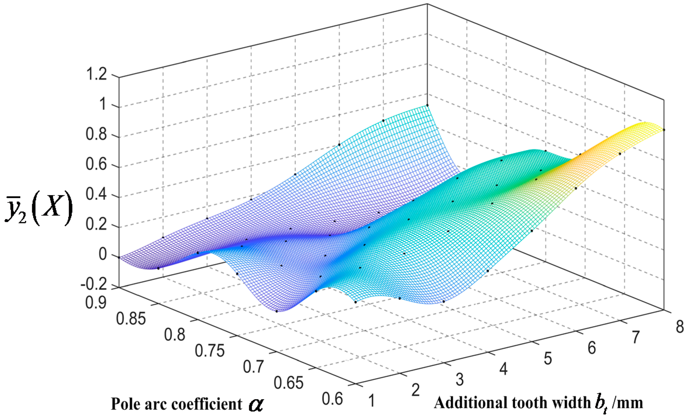
The additional tooth width ba changes from 1 mm to 8 mm with a 1 mm interval and the pole arc coefficient changes from 0.6 to 0.9 with a 0.05 interval. 56 samples were analyzed by using the finite element method (FEM). The normalized objective value and is shown in Table 3 and Table 4. The response surface of two sub objective function is built as shown in Figure 16 and Figure 17.
4.2. Optimization Algorithm (NSGA-II)
The flowchart of the multi-objective optimization design method combining NSGA-II, the Kriging method and FEM is shown in Figure 18. The steps of the NSGA-II algorithm are presented as follows [32,33]:
- Setting the parameters to control the NSGA-II algorithm (number of individuals in the population npop; maximum number of generations ; recombination rate trec and mutation rate tmut) and the range of variables.
- Randomly generate initial populations P0 that satisfy the constraint and calculate the objective function value corresponding to each individual. The objective function value obtained from the surrogate models established by using Kriging method.
- Non-dominated sorting and crowding degree calculation of Pt. Rapid non-dominated sorting based on the objective function values of average electromagnetic torque and torque fluctuation ratio of each individual. The crowding degree is the crowding distance between solution i and neighboring solutions i − 1 and i + 1. This technique can make the solutions evenly distributed in the target space, prevent “stacking” and ensure the global optimization of the algorithm. The crowding distance of the ith individual (L(i)) is defined as following:where, fk is kth objective function value of solution set.
- Perform genetic manipulations, including selection, crossover and mutation. This is the core part of the optimization iteration of NSGA-II algorithm. Subpopulations can be obtained through this step.
- Carry out the elite strategy. Combine the parent populations with sub populations, and generate the next-generation parent population based on non-dominated sorting and crowding degree calculation. Calculate iteratively until the number of iterations gets the maximum number of generations .
Using NSGA-II to perform multi-objective optimization of the surrogate models and established by the Kriging method. The parameters are set as follows: The initial population size npop is 100, the maximum number of the evolution generation is 50, the mutation probability is tmut 0.05, and the recombination probability trec is 0.5.
Figure 19 shows the Pareto front of the average electromagnetic torque and its fluctuation ratio. The points A and C are the optimum design points which can be obtained by single-objective optimization. It can be seen from this figure that choosing appropriate values for design variables for obtaining a better value of one objective would cause a worse value for the other objective. Therefore, it is necessary to select an optimal design scheme in Pareto optimal solutions, so that the electromagnetic torque and torque fluctuation ratio can meet the requirements. For the RDT motor, it is necessary to achieve a given electromagnetic torque, while making the torque fluctuation as small as possible. Setting the electromagnetic torque to 28 Nm, the optimum design points is marked with the red five-pointed star B. The optimum design parameters and objective functions obtained by NSGA-II are shown in Table 5.
4.3. Analysis of Optimization Results
According to the optimal design parameters, a finite element model with additional tooth width of 1.56 mm and pole arc coefficient of 0.883 is established. The electromagnetic torque of the optimized model is shown in Figure 20. Table 6 shows the comparison of the objective functions between the optimal design and initial design. The average torque calculated by the numerical method is 28.089 Nm and the absolute error between the NSGA-II optimization result and the numerical result is 0.076 Nm. The average electromagnetic torque of the optimized model is improved by 16.591% and the fluctuation ratio is reduced to 3.18% when compared with the initial design.
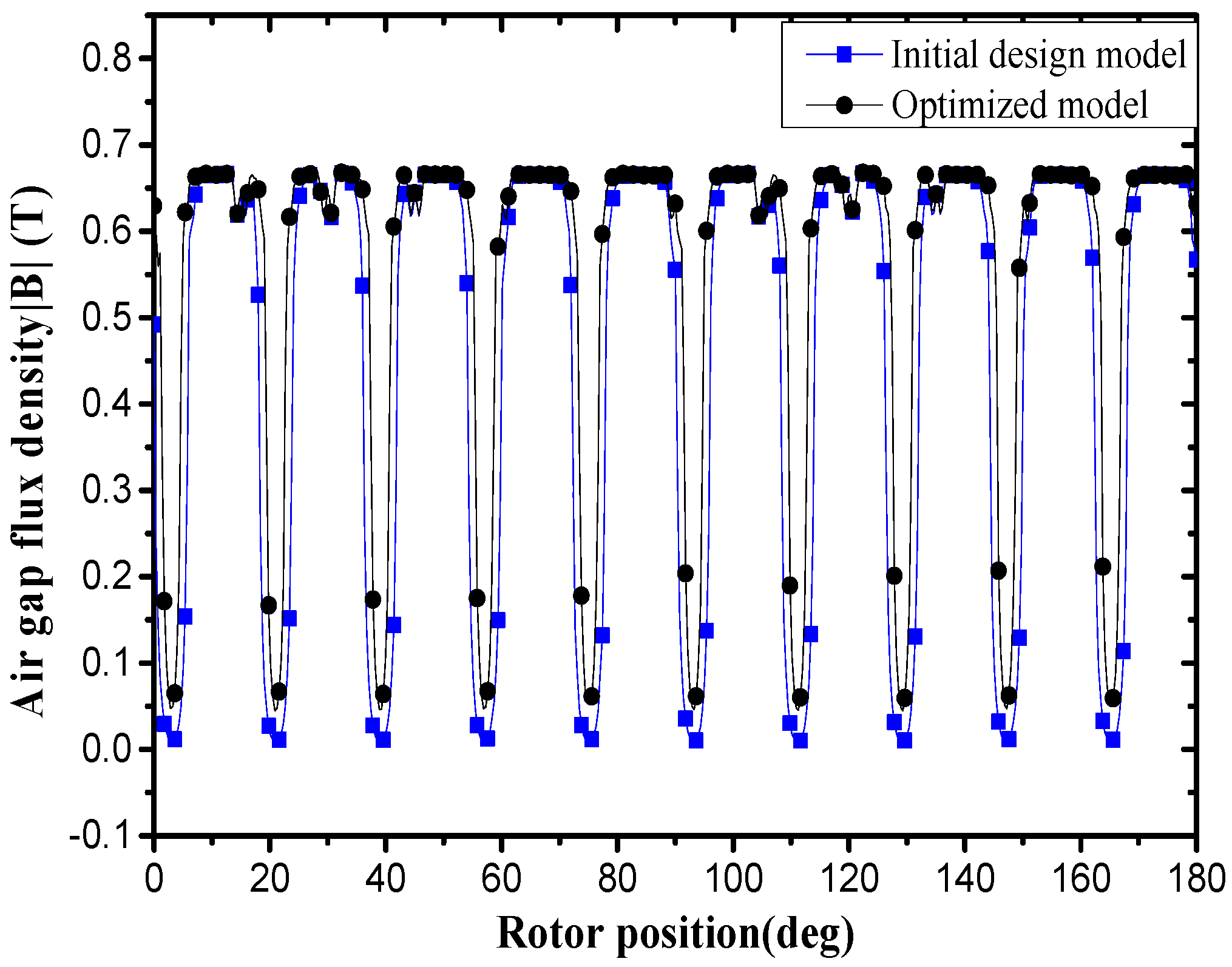
Figure 21 shows the magnetic field distribution of the optimized model and the initial design model. The flux density at the air gap is shown in Figure 22. It can be seen from Figure 20 and Figure 21 that the peak value and the average value of the air gap flux density of the optimized model increase when compared with the initial design model. The effective magnetic flux of the optimized model is also increased, as a result of the pole arc coefficient and additional tooth width change.
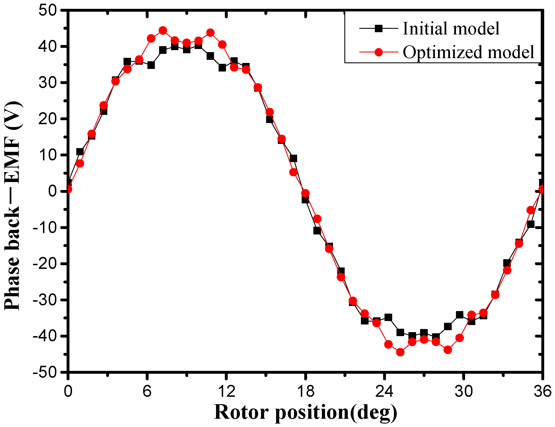
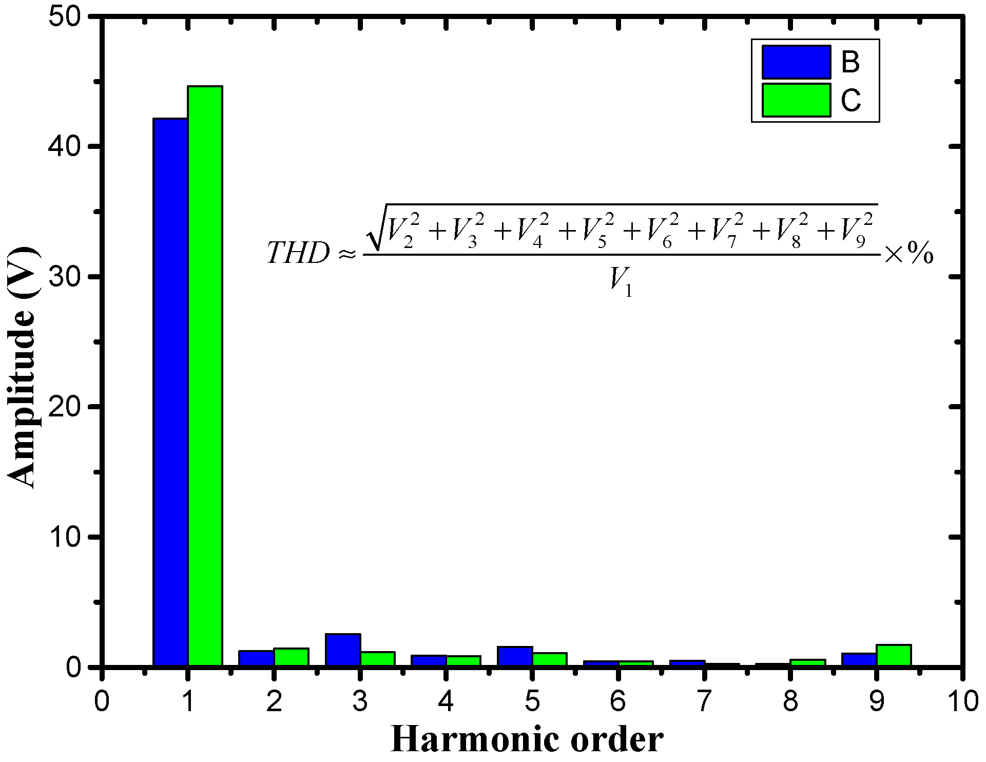
Figure 23 and Figure 24 are the phase back-EMF and its spectra of the initial model and optimized model. It is found that the amplitude of back-EMF of the optimized model larger than that of the initial model, especially the amplitude of fundamental. This is the main reason why the electromagnetic torque of the optimized model is greater than the initial model. The total harmonic distortion (THD) of the optimized model and the initial model are 6.748% and 8.745% respectively. That means the back-EMF of the optimized model is closer to the ideal sine wave, so the fluctuation ratio is smaller than the initial model.
5. Conclusions
In order to improve the performance of the RDT, a stator modular motor is proposed in this paper. Compared with the traditional RDT motor, the stator modular RDT motor could reduce the difficulty of stator processing, shorten the end winding and improve fault tolerance capability. The influence of four design parameters of the new RDT motor on its electromagnetic performance is analyzed, and it is found that the effect of additional tooth width and pole arc coefficient on the electromagnetic performance of the stator modular RDT motor is significant. The average electromagnetic torque and torque fluctuation ratio were taken as the optimization objectives. A hybrid multi-objective optimization design method of the new RDT motor was established combining NSGA-II, the Kriging method and FEM. This method can reduce the design space, cost and computational time of the multi-objective optimization design. A set of Pareto optimal solutions was obtained, and the optimal design point is selected from the Pareto fronts. A finite element RDT motor model with optimal design parameters is established to verify the multi-objective optimization results. Compared with the initial design, the average electromagnetic torque of the optimized model is improved by 16.591% and the fluctuation ratio is reduced to 3.18%. These analysis and optimization results based on FEM provide a theoretical guidance and reference for RDT motor design. Further work will focus on the experimental research of the RDT motor, as well as the multi-level and multi-disciplinary optimization of the overall performance of RDT.
Author Contributions
Y.L. conceived the study and performed the finite element calculation; Y.L., B.S. and Z.M. analyzed the simulation results; Y.L. wrote the manuscript; W.T. reviewed and edited the manuscript.
Acknowledgments
This research was supported by the National Science Foundation of China (Grant No. 51179159), the National Science Foundation of China (Grant No. 61572404) and the Shaanxi Province Youth Science and Technology New Star Project (Grant No.2016KJXX-57).
Conflicts of Interest
The authors declare no conflict of interest.
Nomenclature
| Pin | Input power of RDT |
| Pout | Output mechanical power of RDT |
| Effective value of the input voltage | |
| Effective value of the input current | |
| T | Thrust of propeller |
| Va | Freestream fluid velocity |
| η | Overall efficiency of RDT |
| J | Advance ratio |
| n | Propeller’s rotational speed |
| D | Propeller’s diameter |
| ηm | Efficiency of the motor |
| ηp | Efficiency of the propeller |
| kL | Mechanical loss coefficient |
| Te | Electromagnetic torque |
| KT | Total thrust coefficient |
| KQ | Total torque coefficient |
| KTB | Thrust coefficient of propeller |
| KQB | Torque coefficient of propeller |
| KTN | Thrust coefficient of duct |
| KQN | Torque coefficient of duct |
| TB | Thrust of propeller |
| QB | Torque of propeller |
| TN | Thurst of duct |
| QN | Torque of duct |
| θ | Rotor position angle |
| Wm | Magnetic field energy |
| BPr | Radial components of the main magnetic field |
| BWr | Radial components of the armature winding magnetic field |
| ba | Width of additional tooth |
| ha | height of additional tooth |
| bs | Slot opening width |
| bt | Width of stator tooth |
| α | Pole arc coefficient |
References
- Zhang, Z.H.; Nie, S.L.; Zhang, L.M.; Yuan, S.H. Development of seawater hydraulic pump tester in deep-sea simulated environment. In Proceedings of the International Conference, Fluid Power Mechatron, Harbin, China, 5–7 August 2015; pp. 667–671. [Google Scholar]
- Traverso, P.; Canepa, E. A review of studies on corrosion of metals and alloys in deep-sea environment. Ocean Eng. 2014, 87, 10–15. [Google Scholar] [CrossRef]
- Islam, M.; Veitch, B.; Liu, P. Uncertainty of measurements of podded propulsor performance characteristics. Ocean Eng. 2014, 81, 130–138. [Google Scholar] [CrossRef]
- Smallwood, D.; Bachmayer, R.; Whitcomb, L.L. A new remotely operated underwater vehicle for dynamics and control research. In Proceedings of the International Symposium, Unmanned Untethered Submersible Technology, Durham, NH, USA, 19–22 September 1999; pp. 370–377. [Google Scholar]
- Sharkh, S.M.A.; Turnock, S.R.; Hughes, A.W. Design and performance of an electric tip-driven thruster. Proc. Inst. Mech. Eng. Part M 2003, 217, 133–147. [Google Scholar] [CrossRef]
- Liang, J.; Zhang, X.; Qiao, M.; Zhu, P.; Cai, W.; Xia, Y.; Li, G. Optimal design and multifield coupling analysis of propelling motor used in a novel integrated motor propeller. IEEE Trans. Magn. 2013, 49, 5742–5748. [Google Scholar] [CrossRef]
- Song, B.W.; Wang, Y.J.; Tian, W.L. Open water performance comparison between hub-type and hubless rim driven thrusters based on CFD method. Ocean Eng. 2015, 103, 55–63. [Google Scholar] [CrossRef]
- Yan, X.; Liang, X.; Ouyang, W.; Liu, Z.; Liu, B.; Lan, J. A review of progress and applications of ship shaft-less rim-driven thrusters. Ocean Eng. 2017, 144, 142–156. [Google Scholar] [CrossRef]
- Lea, M.; Thompson, D.; Van Blarcom, B.; Eaton, J.; Friesch, J.; Richards, J. Scale model testing of a commercial rim-driven propulsor pod. J. Ship Prod. 2003, 19, 121–130. [Google Scholar]
- Dubas, A.J. Robust Automated Computational Fluid Dynamics Analysis and Design Optimisation of Rim Driven Thrusters. Ph.D. Dissertation, University of Southampton, Southampton, UK, 2014. [Google Scholar]
- Shen, Y.; Hu, P.; Jin, S. Design of novel shaftless pump-jet propulsor for multi-purpose long-range and high-speed autonomous underwater vehicle. IEEE Trans. Magn. 2016, 52, 1–4. [Google Scholar] [CrossRef]
- Sharkh, S.M.A.; Lai, S.H.; Turnock, S.R. Structurally integrated brushless pm motor for miniature propeller thrusters. IEEE Proc. Electr. Power Appl. 2004, 151, 513–519. [Google Scholar] [CrossRef]
- Krøvel, Ø.; Nilssen, R.; Skaar, S.E.; Lovli, E.; Sandoy, N. Design of an integrated 100kw permanent magnet synchronous machine in a prototype thruster for ship propulsion. In Proceedings of the 16th International Conference on Electrical Machines ICEM, Cracow, Poland, 5–8 September 2004; pp. 117–123. [Google Scholar]
- Djebarri, S.; Charpentier, J.F.; Scuiller, F.; Benbouzid, M.; Guemard, S. Rough design of a double-stator axial flux permanent magnet generator for a rim-driven marine current turbine. In Proceedings of the 2012 IEEE International Symposium on Industrial Electronics, Hangzhou, China, 28–31 May 2012; pp. 1450–1455. [Google Scholar]
- Duan, Y.; Dan, M.I. A review of recent developments in electrical machine design optimization methods with a permanent magnet synchronous motor benchmark study. IEEE Trans. Magn. 2013, 49, 1268–1275. [Google Scholar] [CrossRef]
- Lei, G.; Liu, C.; Zhu, J.; Guo, Y. Techniques for multilevel design optimization of permanent magnet motors. IEEE Trans. Energy Convers. 2015, 30, 1574–1584. [Google Scholar] [CrossRef]
- Wang, H.T.; Liu, Z.J.; Chen, S.X.; Yang, J.P. Application of Taguchi method to robust design of BLDC motor performance. IEEE Trans. Magn. 1999, 35, 3700–3702. [Google Scholar] [CrossRef]
- Hwang, C.C.; Chang, C.M.; Liu, C.T. A fuzzy-based Taguchi method for multiobjective design of PM motors. IEEE Trans. Magn. 2013, 49, 2153–2156. [Google Scholar] [CrossRef]
- Omekanda, A.M. Robust torque and torque-per-inertia optimization of a switched reluctance motor using the Taguchi methods. IEEE Trans. Ind. Appl. 2006, 42, 473–478. [Google Scholar] [CrossRef]
- Pan, G.; Cheng, B.; Zhang, P.; Cao, Y. Coupling design and performance analysis of rim-driven integrated motor propulsor. In Proceedings of the MTS/IEEE Oceans’16, Shanghai, China, 10–13 April 2016; pp. 1–6. [Google Scholar]
- Bontempo, R.; Cardone, M.; Manna, M. Performance analysis of ducted marine propellers. Part I–Decelerating duct. Appl. Ocean Res. 2016, 58, 322–330. [Google Scholar] [CrossRef]
- Bhattacharyya, A.; Krasilnikov, V.; Steen, S. A CFD-based scaling approach for ducted propellers. Ocean Eng. 2016, 123, 116–130. [Google Scholar] [CrossRef]
- Marinescu, M.; Marinescu, N. Numerical computation of torques in permanent magnet motors by Maxwell stresses and energy method. IEEE Trans. Magn. 1988, 24, 463–466. [Google Scholar] [CrossRef]
- Fu, W.N.; Zhou, P.; Lin, D. Magnetic force computation in permanent magnets using a local energy coordinate derivative method. IEEE Trans. Magn. 2004, 40, 683–686. [Google Scholar] [CrossRef]
- Lei, G.; Wang, T.; Zhu, J.; Guo, Y.; Wang, S. System-level design optimization method for electrical drive systems—Robust approach. IEEE Trans. Ind. Electron. 2015, 62, 4702–4713. [Google Scholar] [CrossRef]
- Ma, B.; Lei, G.; Liu, C.; Zhu, J.; Guo, Y. Robust tolerance design optimization of a pm claw pole motor with soft magnetic composite cores. IEEE Trans. Magn. 2017, 99, 1–4. [Google Scholar] [CrossRef]
- Vo-Duy, T.; Duong-Gia, D.; Ho-Huu, V.; Vu-Do, H.C.; Nguyen-Thoi, T. Multi-objective optimization of laminated composite beam structures using NSGA-II algorithm. Compos. Struct. 2017, 168, 498–509. [Google Scholar] [CrossRef]
- Deb, K.; Pratap, A.; Agarwal, S.; Meyarivan, T. A fast and elitist multiobjective genetic algorithm: NSGA-II. IEEE Trans. Evol. Comput. 2002, 6, 182–197. [Google Scholar] [CrossRef] [Green Version]
- Martin, J.D.; Simpson, T.W. Use of kriging models to approximate deterministic computer models. AIAA J. 2005, 43, 853–863. [Google Scholar]
- Tian, W.; Mao, Z.; Zhang, B. Shape optimization of a savonius wind rotor with different convex and concave sides. Renew. Energy 2018, 117, 287–299. [Google Scholar] [CrossRef]
- Zhang, B.; Song, B.; Mao, Z.; Tian, W. A novel wake energy reuse method to optimize the layout for Savonius-type vertical axis wind turbines. Energy 2017, 121, 341–355. [Google Scholar] [CrossRef]
- Pereira, L.A.; Haffner, S.; Nicol, G.; Dias, T.F. Multiobjective optimization of five-phase induction machines based on NSGA-II. IEEE Trans. Ind. Electron. 2017, 64, 9844–9853. [Google Scholar] [CrossRef]
- Zhang, L.; Zhang, J.Y.; Tian, L.I.; Zhang, Y.D. Multi-objective aerodynamic optimization design of high-speed train head shape. JZUS-A 2017, 18, 841–854. [Google Scholar] [CrossRef]
Figure 1.
Structure of RDT.

Figure 2.
Traditional RDT (a) Prototype of RDT and (b) Overall efficiency of RDT at different J.
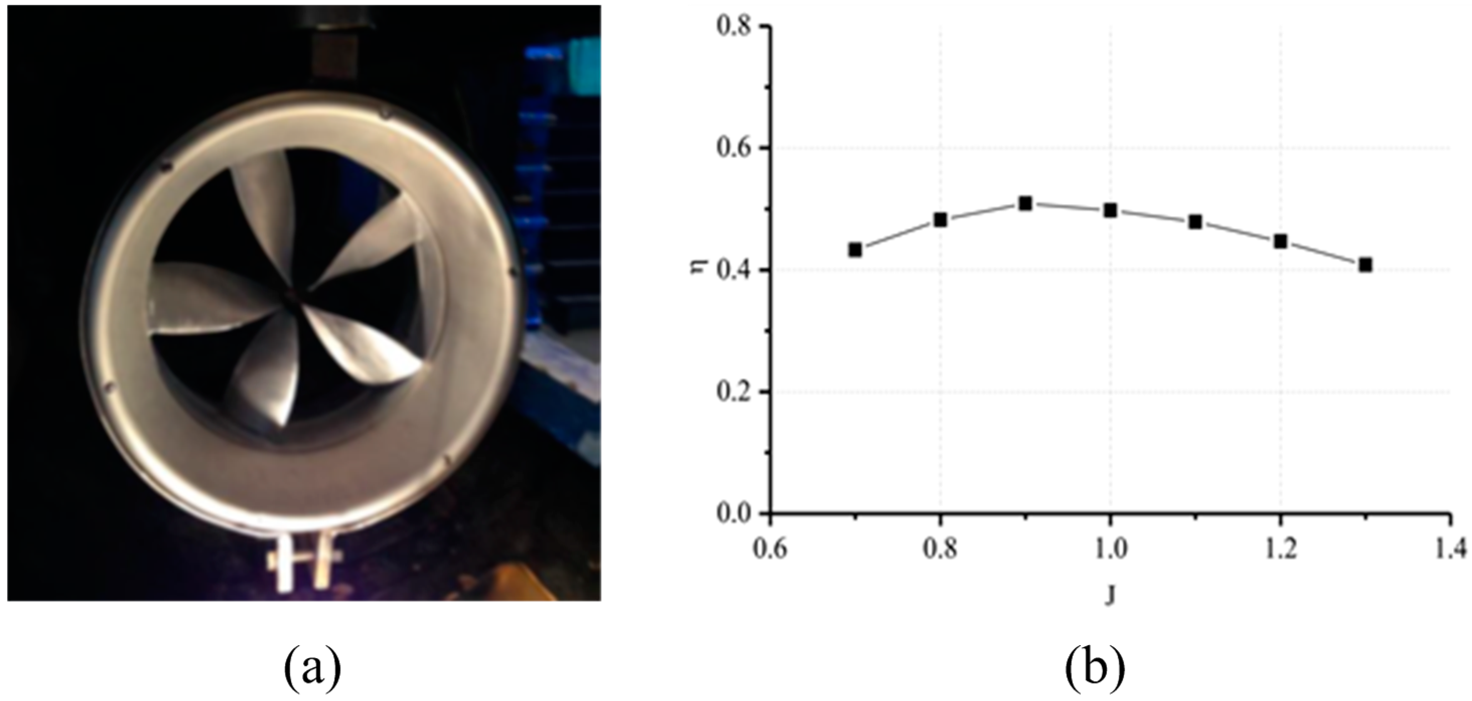
Figure 3.
Stator armature of traditional RDT motor.

Figure 4.
Structure of the stator of the new RDT.

Figure 5.
Structure parameters of the stator of the new RDT motor.

Figure 6.
Comparison of the phase back electromotive force (back—EMF).

Figure 7.
Static magnetic field distribution (a) Traditional RDT motor (b) Stator modular RDT motor.
Figure 7.
Static magnetic field distribution (a) Traditional RDT motor (b) Stator modular RDT motor.

Figure 8.
Normalized phase back–EMF.

Figure 9.
Harmonic analysis of the phase back–EMF.

Figure 10.
Electromagnetic torque.

Figure 11.
Cogging torque.

Figure 12.
Influence of the slot opening width (a) Cogging torque (b) Back—EMF (c) Harmonic analysis of the phase back—EMF (d) Average electromagnetic torque (e) Fluctuation ratio of electromagnetic torque (f) Iron loss.
Figure 12.
Influence of the slot opening width (a) Cogging torque (b) Back—EMF (c) Harmonic analysis of the phase back—EMF (d) Average electromagnetic torque (e) Fluctuation ratio of electromagnetic torque (f) Iron loss.

Figure 13.
Influence of the additional tooth height (a) Cogging torque (b) Back—EMF (c) Average electromagnetic torque (d) Fluctuation ratio of electromagnetic torque (e) Iron loss.
Figure 13.
Influence of the additional tooth height (a) Cogging torque (b) Back—EMF (c) Average electromagnetic torque (d) Fluctuation ratio of electromagnetic torque (e) Iron loss.
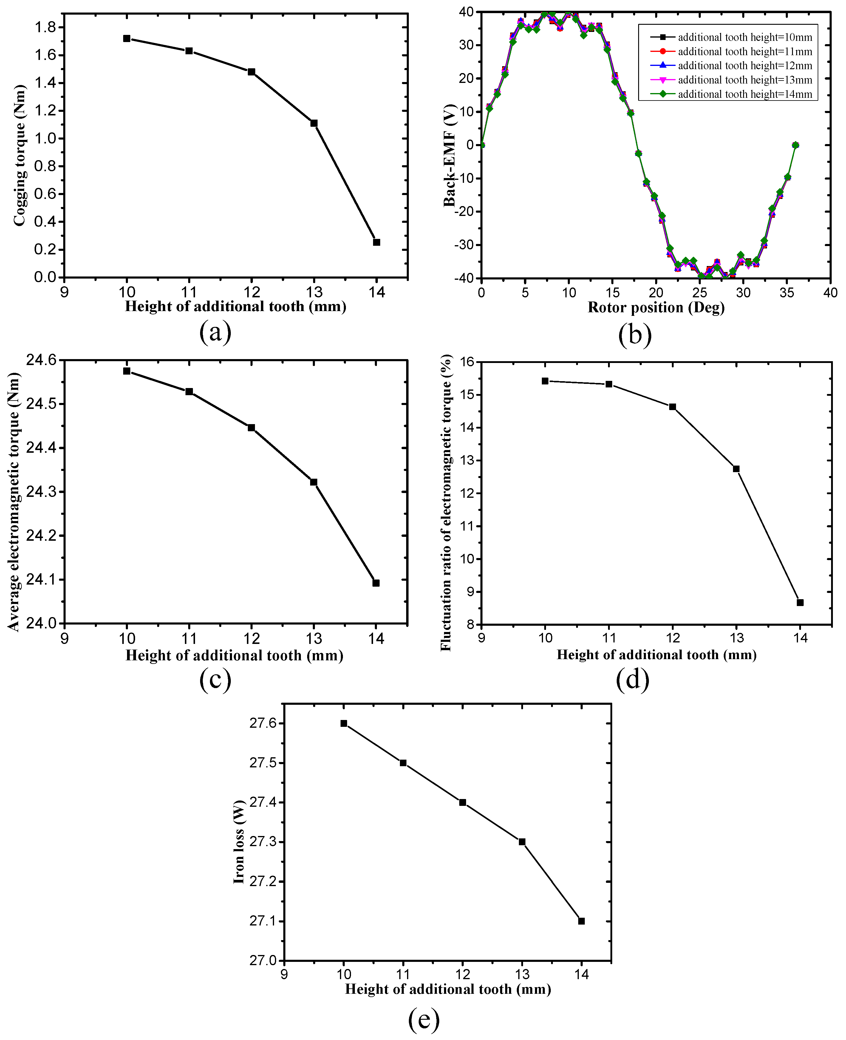
Figure 14.
Influence of the additional tooth width (a) Cogging torque (b) Back—EMF (c) Harmonic analysis of the phase back EMF (d) Average electromagnetic torque (e) Fluctuation ratio of electromagnetic torque (f) Iron loss.
Figure 14.
Influence of the additional tooth width (a) Cogging torque (b) Back—EMF (c) Harmonic analysis of the phase back EMF (d) Average electromagnetic torque (e) Fluctuation ratio of electromagnetic torque (f) Iron loss.

Figure 15.
Influence of the pole arc coefficient (a) Cogging torque (b) Back-EMF (c) Harmonic analysis of the phase back EMF (d) Average electromagnetic torque (e) Fluctuation ratio of electromagnetic torque (f) Iron loss.
Figure 15.
Influence of the pole arc coefficient (a) Cogging torque (b) Back-EMF (c) Harmonic analysis of the phase back EMF (d) Average electromagnetic torque (e) Fluctuation ratio of electromagnetic torque (f) Iron loss.
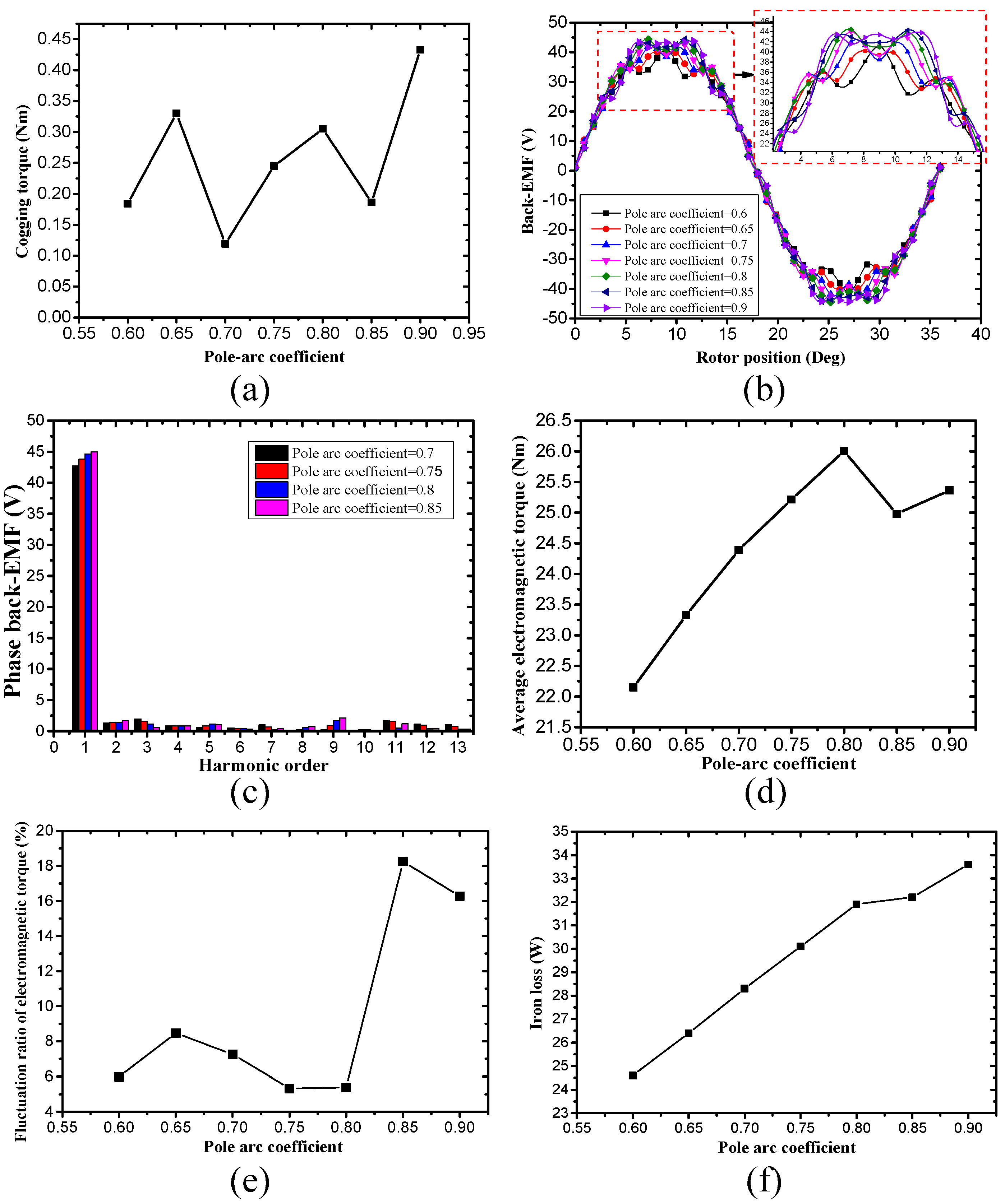
Figure 16.
Response surface of sub objective function .
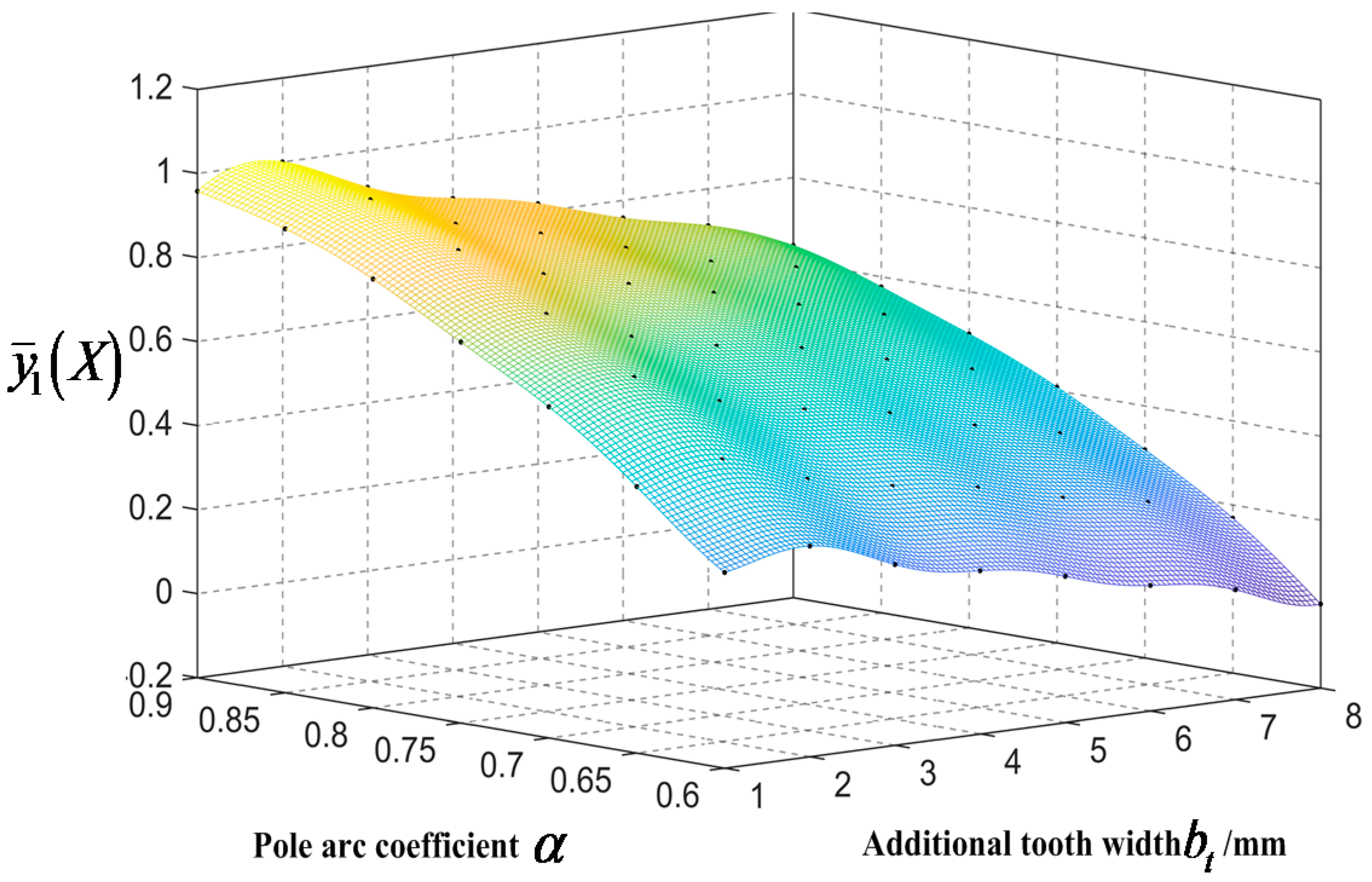
Figure 17.
Response surface of sub objective function .

Figure 18.
Flowchart of the multi-objective optimization design method combining NSGA-II, the Kriging method and FEM.
Figure 18.
Flowchart of the multi-objective optimization design method combining NSGA-II, the Kriging method and FEM.

Figure 19.
Pareto front of two optimization objectives.

Figure 20.
Electromagnetic torque of the optimized model.

Figure 21.
Magnetic field distribution (a) Initial design model (b) Optimized model.
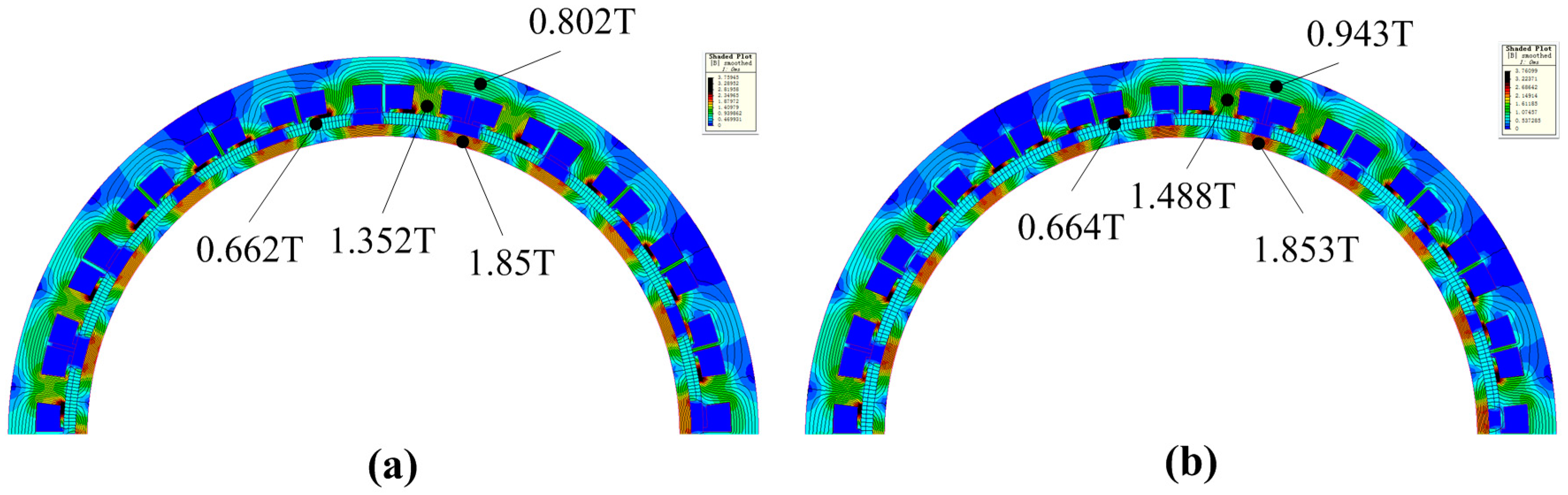
Figure 22.
Air gap flux density.

Figure 23.
Phase back—EMF of the initial model and the optimized model.

Figure 24.
Spectra of phase back-EMF of the initial model and the optimized model.


Table 1.
Main parameters of two RDT motors.
| Main Parameters | Traditional RDT Motor | Initial Stator Modular RDT Motor |
|---|---|---|
| Stator outer diameter (mm) | 380 | 380 |
| Stator inner diameter (mm) | 324 | 324 |
| Stack length (mm) | 39 | 39 |
| Air gap length (mm) | 2.5 | 2.5 |
| Pole number | 20 | 20 |
| Magnet thickness (mm) | 3.5 | 3.5 |
| Rotor inner diameter (mm) | 300 | 300 |
| Slot number | 60 | 24 |
| Slot opening width bs (mm) | 2.8 | 2.0 |
| Tooth width (mm) | 6.6 | 14.5 |
| Height of additional tooth ha (mm) | --- | 14 |
| Width of additional tooth ba (mm) | --- | 2.0 |
| Pole arc coefficient α | 0.67 | 0.67 |
| Number of coil turns/phase | 90 | 100 |
| Number of parallel branches | 2 | 2 |
| Wire diameter (mm) | 2.3 | 4.3 |
| Slot filling factor | 77% | 77% |
| Phase resistance (Ω) | 0.1186 | 0.033 |
Table 2.
Zigzag leakage coefficient.
| RDT Motor | Traditional RDT Motor | Stator Modular RDT Motor |
|---|---|---|
| Zigzag Leakage Coefficient | 1.064 | 1.233 |
Table 3.
Normalized objective value .
| Additional Tooth Width ba/mm | |||||||||
|---|---|---|---|---|---|---|---|---|---|
| 1 | 2 | 3 | 4 | 5 | 6 | 7 | 8 | ||
| Pole arc coefficient α | 0.60 | 0.2655 | 0.3012 | 0.223 | 0.1881 | 0.1474 | 0.0987 | 0.0612 | 0 |
| 0.65 | 0.4340 | 0.4709 | 0.3968 | 0.3527 | 0.3219 | 0.2704 | 0.2326 | 0.1683 | |
| 0.70 | 0.5879 | 0.6305 | 0.5461 | 0.4992 | 0.4631 | 0.4062 | 0.3606 | 0.2954 | |
| 0.75 | 0.7061 | 0.7449 | 0.6632 | 0.6145 | 0.5818 | 0.5273 | 0.477 | 0.4083 | |
| 0.80 | 0.8202 | 0.8606 | 0.7764 | 0.7259 | 0.6775 | 0.6219 | 0.5709 | 0.4988 | |
| 0.85 | 0.9039 | 0.9454 | 0.8602 | 0.8096 | 0.7485 | 0.6887 | 0.6478 | 0.5752 | |
| 0.90 | 0.9574 | 1 | 0.9123 | 0.8589 | 0.8191 | 0.7574 | 0.7125 | 0.6381 | |
Table 4.
Normalized objective value .
| Additional Tooth Width ba/mm | |||||||||
|---|---|---|---|---|---|---|---|---|---|
| 1 | 2 | 3 | 4 | 5 | 6 | 7 | 8 | ||
| Pole arc coefficient α | 0.60 | 0.3438 | 0.2984 | 0.2072 | 0.3407 | 0.5378 | 0.7509 | 0.9109 | 1 |
| 0.65 | 0.3101 | 0.3927 | 0.4173 | 0.4965 | 0.6104 | 0.7005 | 0.7979 | 0.889 | |
| 0.70 | 0.0693 | 0.228 | 0.3685 | 0.4678 | 0.5172 | 0.5547 | 0.5833 | 0.5985 | |
| 0.75 | 0.2113 | 0.1931 | 0.1895 | 0.3083 | 0.4164 | 0.495 | 0.5429 | 0.5364 | |
| 0.80 | 0.2455 | 0.2149 | 0.1785 | 0.1466 | 0.1407 | 0.225 | 0.3065 | 0.3492 | |
| 0.85 | 0.0343 | 0.0584 | 0.0829 | 0.0845 | 0.0645 | 0.0519 | 0.067 | 0.1395 | |
| 0.90 | 0 | 0.0612 | 0.1177 | 0.1729 | 0.2716 | 0.4001 | 0.4907 | 0.5224 | |
Table 5.
Optimum design parameters and objective functions.
| Variable | Value |
|---|---|
| bt (mm) | 1.56 |
| α | 0.883 |
| Te (Nm) | 28.013 |
| Kt (%) | 3.037 |
Table 6.
Comparison of the objective functions between the optimum design and initial design.
| Type of the Design | Optimum Design (FEM) | Initial Design | |
|---|---|---|---|
| Objective functions | Te (Nm) | 28.089 | 24.092 |
| Kt (%) | 3.18 | 8.669 | |
© 2018 by the authors. Licensee MDPI, Basel, Switzerland. This article is an open access article distributed under the terms and conditions of the Creative Commons Attribution (CC BY) license (http://creativecommons.org/licenses/by/4.0/).
Share and Cite
MDPI and ACS Style
Li, Y.; Song, B.; Mao, Z.; Tian, W. Analysis and Optimization of the Electromagnetic Performance of a Novel Stator Modular Ring Drive Thruster Motor. Energies 2018, 11, 1598. https://doi.org/10.3390/en11061598
AMA Style
Li Y, Song B, Mao Z, Tian W. Analysis and Optimization of the Electromagnetic Performance of a Novel Stator Modular Ring Drive Thruster Motor. Energies. 2018; 11(6):1598. https://doi.org/10.3390/en11061598
Chicago/Turabian StyleLi, Yukai, Baowei Song, Zhaoyong Mao, and Wenlong Tian. 2018. "Analysis and Optimization of the Electromagnetic Performance of a Novel Stator Modular Ring Drive Thruster Motor" Energies 11, no. 6: 1598. https://doi.org/10.3390/en11061598
Note that from the first issue of 2016, this journal uses article numbers instead of page numbers. See further details here.