A New Plugging Technology and Its Application for the Extensively Collapsed Ore Pass in the Non-Empty Condition


1
School of Civil and Resource Engineering, University of Science and Technology Beijing, Beijing 100083, China
2
BGRIMM Technology Group, Beijing 100160, China
3
Beijing General Research Institute of Mining & Metallurgy, Beijing 100160, China
4
National Center for International Research on Green Mining of Metallic Mines, Beijing 102628, China
*
Author to whom correspondence should be addressed.
Energies 2018, 11(6), 1599; https://doi.org/10.3390/en11061599
Submission received: 25 April 2018
/
Revised: 11 June 2018
/
Accepted: 14 June 2018
/
Published: 19 June 2018
Abstract
:Aiming at some long ore passes with severe damages and extensive collapses, we describe an optimal measure to plug a local area of ore pass in order to maintain the capacity of continued use. This paper, taking a new plug for the extensively collapsed long ore pass in the non-empty condition as a breakthrough, builds a structure-plugging system for ore pass based on plug effect, suspension effect, arch effect, and span-reducing effect. Meanwhile, a key plugging technology has been integrated which includes a stability evaluation method of plugging structure, controlled technology of drilling with casing in the composite rock mass, and controllable grouting for inhomogeneous loose rock mass. According to this structure-plugging system and technology, a case has been successful for the main ore pass in the Xingshan Iron Mine in China, which has created a precedent in the world. The practice results show that using this technology to plug the extensively collapsed long ore pass has a series of advantages including of scientific design, strong safety, high efficiency, and low cost.
1. Introduction
Restricted by geological conditions, loss of long-term use, and other objective conditions, long ore passes in Chinese mines generally suffer from some disasters such as large-scale and large-span collapse [1,2,3,4], frequent arching, and blocking [5,6,7]. These disasters seriously limit the longevity of long ore passes [8] and the normal production of mines. Some long ore passes had been discarded after a short use. It is one of the effective measures to plug a local area of the extensively collapsed long ore pass in order to maintain the capacity of continued use.
Many special problems such as uncertain collapse shape, large collapse span, and being near some underground permanent structures are often faced when plugging an extensively collapsed long ore pass. Therefore, it is extremely dangerous to plug an extensively collapsed long ore pass in the empty condition.
The research and practice nationally and abroad for the extensively collapsed long ore pass mainly include several aspects as follows:
First, there are different solutions and repeated arguments for the design and reinforcement of long ore passes, ensuring a reliable longevity of the long ore pass from the beginning [9,10,11]. Second, through the scanning of collapsed long ore passes [12,13] and the analysis and verification of their damage mechanisms under impact conditions [12,13,14,15], the feedback can be used to design follow-up long ore passes. Third, there have been some attempts made such as plugging the extensively collapsed long ore pass under non-empty conditions by drilling and grouting to loosen rock mass at the same time [16], and filling with concrete under an empty long ore pass [17,18]. However, the above practices have some various defects such as low construction speed and the high risk of the ore pass being empty.
Considering the feasibility of technology and reasonability of economy, in order to maintain a long use of the extensively collapsed long ore pass, plugging a local area of the long ore pass and using its lower segment becomes an optimal strategy. However, the above research works about long ore passes are only limited in theory, experimental research, and technology exploration, and there have been very few cases for an efficient plugging of the extensively collapsed long ore pass; moreover, there is not a complete theoretical and technical system for plugging ore passes from theory to test, design, and apply in case studies.
In terms of so many difficulties faced by plugging for the extensively collapsed long ore pass, this paper proposes a method of plugging the extensively collapsed long ore pass in the non-empty condition. Based on the collaborative concept of overall design with local design, a structure-plugging system for ore passes in the non-empty condition has been built, and around this structure system a plugging technology has been integrated which includes a stability evaluation method of plugging structure, controlled technology of drilling with casing in the composite rock mass, and controllable grouting technology for the inhomogeneous loose rock mass. Under the guidance of the structure-plugging system and technology, a case has been successful for the main ore pass in the Xingshan Iron Mine in China, which has created a world precedent by using the technology to plug an extensively collapsed long ore pass in the non-empty condition.
2. Construction of Structure-Plugging System for the Extensively Collapsed Long Ore Pass in the Non-Empty Condition
When constructing a structure-plugging system of ore passes which demands that the ore pass is in the non-empty condition and that no person enters inside it, some prominent problems must be fully considered, such as the random arrangement of different block sizes (ore powder, large ore blocks, collapsed waste rocks, etc.), large collapse span of the ore pass (>10 m), complex collapsed shapes, and vertical load caused by several hundred meters of loose rock mass. Therefore, the structure-plugging system should separately solve each problem and carry out multiple control countermeasures on the above problems, finally reaching an optimal outcome in the safety, efficiency, and low cost of the plugging engineering of the ore pass. In terms of the above prominent problems and based on the scientific and collaborative concept of overall design with local design, several effects, including of plug effect, suspension effect, arch effect, and span-reducing effect, have been applied to the design of the structure-plugging system of extensively collapsed long ore passes [2], as shown in Figure 1.
Plug effect: finding the smallest section of the ore pass near the construction site by combining drilling with the original design of the ore pass and forming a plug structure by controllable grouting to loosen rock mass above this section; then the plug effect could be realized from the overall design concept of the plugging structure.
Suspension effect: by constructing double-sided holes by the method of drilling of casing at the construction site and installing large-span prestressed cables with a long distance in these holes, the double-sided suspension structure with stayed cables is formed; then the suspension effect could be conceived from the overall design of the plugging structure.
Arch effect: by using the randomly distributed characteristic of grouting cracks, structure feature of controllable grouting, and optimized arrangement of double-sided stayed cables, an arch structure can be formed automatically after outflow of the lower waste rocks in the ore pass. This is the arch effect from the local design of the plugging structure.
Span-reducing effect: by arranging intensive composite bars combined casing with prestressed cables, the span and height of the arch formed automatically could be reduced, and at the same time, the stability of the lower part of the plugging structure could be improved. These behaviours can realize the span-reducing effect of the local design.
3. Integration of Plugging Technology for the Extensively Collapsed Long Ore Pass in the Non-Empty Condition
Based on four major mechanical effects to build the structure-plugging system for ore passes in the non-empty condition, to realize an efficient plugging for the extensively collapsed ore pass, several problems are faced as follows:
- Stability evaluation of the structure-plugging system.
- Drilling in the composite rock mass from hard rock to loose rock mass.
- How to achieve full grouting to the bulk and loose rock mass in the plugging area.
- How to ensure that grout does not block the lower part of the plugging area.
Therefore, it is necessary to solve the above problems and ultimately integrate a new plugging technology for the extensively collapsed long ore pass in the non-empty condition.
3.1. Stability Evaluation Method of the Plugging Structure
The stability evaluation of the plugging structure is mainly determined based on the overall stress states of the plugging structure. As the plugging structure of the ore pass in the non-empty condition possesses some features such as large height, low integrity (compared with the reinforced concrete structure), and so forth, shear failure is determined as the main instability mode by which to evaluate the stability of the plugging structure after considering different types of failure.
In the shear failure mode, there are two main potential shear sliding planes (Figure 2): (i) the interface between the ore pass wall with the original rock and plugging structure; (ii) the sliding interface inside the plugging structure. Mechanical model ① and mechanical model ② corresponding to two types of shear failure mode of a plugging structure are shown in Figure 2.
Based on the two main potential shear sliding planes, the safety factor of a plugging structure is calculated as follows:
where fs is the safety factor of the plugging structure; F is the capacity to resist the slide of the plugging structure, in kN; and N is the sum of vertical pressure of loose rock mass and the weight of the plugging structure itself, in kN.
where qi is the surface load of vertical pressure on top of the plugging structure [19,20,21,22], in kPa; Aa is the area involved in the calculation, in m2, and according to the mechanical model, Aa takes the area respectively corresponding to mechanical model ① and ②; GAa is the weight of the plugging structure, in kN; G = γAaH, where γ is the unit weight of the plugging structure, in kN/m3, and H is the height of the plugging structure, in m.
where τnj is the shear strength of the fracture plane corresponding to mechanical model ① or mechanical model ②, in kPa; Ba is the fracture surface area inside the plugging structure involved in the calculation, in m2, and according to different mechanical models for calculation, Ba takes the area of the fracture plane corresponding to mechanical model ① and mechanical model ②, respectively; Ttk is the axial tensile of a single composite bar combined casing with prestressed cable, in kN; Ftk is the section force to resist the shear of a single composite bar, in kN; αk is the dip angle of a single composite bar, in degrees; k is the number of composite bars.
where σnj is the normal compressive stress on the fracture plane, in kPa; φa is the friction angle of the fracture plane corresponding to mechanical model ① or mechanical model ②, in degrees; Ca is the cohesion of the fracture plane corresponding to mechanical model ① or mechanical model ②, in kPa. φa and Ca of fracture planes are selected by taking into account multiple factors due to their particularity [23,24,25,26,27,28].
where hja is the height of the point on the fracture plane involved in the calculation, in m; λ is the lateral pressure coefficient of the point on the fracture plane involved in the calculation.
fs = F/N
N = ∮Aa qids + GAa
τnj = σnjtanφa + ca
σnj = (qi + rhja) × λ
The steady state and design parameters of a plugging structure in the non-empty condition could be evaluated by calculating the safety factors of two mechanical models according to the above formulas. Based on a full consideration of permanent engineering and its importance grade nationally and abroad, the safety factor of a plugging structure for the extensively collapsed ore pass shall meet fs ≥ 1.35; generally, this safety factor should be raised appropriately due to the inhomogeneous grouting of loose rock mass.
3.2. Controlled Technology of Drilling with Casing in the Composite Rock Mass
In the drilling process from hard rock near the working space to loose rock mass located in the extensively collapsed ore pass, two main problems need to be solved as follows:
(i) Frequent sticking. This phenomenon mainly occurs in the interface between hard rock and loose rock mass due to the high pneumatic DTH (down-the-hole drill) being unsuitable to loose rock mass (as is shown in ① of Figure 3).
(ii) A high frequency of broken casing. In order to enable the subsequent grouting of loose rock mass located in the ore pass, a large number of dense grout vents are bored in the casing body. However, this operation causes severe damage to the casing body, and in addition to the brittleness of casing itself, some broken casing accidents easily happen in the process of the drilling of casing (as shown in ② of Figure 3).
3.2.1. A Technology to Solve Sticking in the Interface between Hard Rock and Loose Rock Mass
Engineering practice shows that the sticking in the interface between hard rock and loose rock mass is caused by a sudden transition from hard rock to loose rock mass in the use of the original high pneumatic DTH. The rubble that causes sticking only blows up and falls back to the original location repeatedly along the axial direction of the drill rod under an intermittent high pneumatic pressure, but actually they still remain where the sticking happens. Therefore, the drill cannot be pulled out from the sticking position.
To solve this problem, three holes, where the mutual angle is 120° around the circumference of the drill rod, are drilled in the front section of the first drill rod connected with the DTH (Figure 4). The holes’ arrangement alters the wind current direction from being one-dimensional to three-dimensional near the DTH, so the rubble is moved away easily. This kind of drill rod can solve sticking in the DTH process, and in particular, it is significantly effective in preventing sticking in the complex and fractured ground.
3.2.2. A Technology to Effectively Reduce the Frequency of Broken Casing during a Long-Distance Process of the Drilling of Casing
A series of broken casings frequently occurs in the process of the drilling of casing, which is caused by some details such as the incline occurring in the long-distance process of the drilling of casing, fulcrum deflection in the interface between hard rock and loose rock mass, severe damage caused by dense grout vents to the casing body, and the brittleness of the casing itself. So, the high frequency of broken casing had become a tough issue in the early exploratory construction of the extensively collapsed ore pass in the Xingshan Iron Mine which was undertaken by the BGRIMM Technology Group.
By limiting the spacing to no less than 30 cm between grout vents and having only one grout vent on a single section of the casing body, a plum-shaped arrangement of grout vents, and the diameter of the grout vent no more than 15 mm (Figure 5), the problem of broken casing has been solved in the casing process from hard rock to loose rock mass. These arrangement parameters have been applied and verified at the normal stage of plugging to the main ore pass in the Xingshan Iron Mine, and no broken casing accidents occurred during the construction.
3.3. Controllable Grouting Technology for the Inhomogeneous Loose Rock Mass
To effectively plug the extensively collapsed ore pass, two basic conditions must be ensured as follows:
- (i)
- Grouting for the inhomogeneous loose rock mass as tightly as possible in the plugging area;
- (ii)
- Ensuring that grout will not block the incline ore pass and the part of ore pass below the plugging area so that subsequent use can be restored as soon as possible.
The above two basic conditions are contradictory to each other. To solve this pair of contradictions, it is necessary to coordinate and control the grout type, grout diffusion range, and grouting method so that controllable grouting is achieved for inhomogeneous loose rock mass [29,30].
3.3.1. Diffusion Characteristics of Cement–Silicate Grout in the Loose Rock Mass
When general cement grout is grouted for loose rock mass, its diffusion range is very high. In order to ensure that grouting in the loose rock mass will not block the incline ore pass below the plugging area, cement–silicate (C–S) grout is selected to control the diffusion range of the grouting.
In order to obtain the diffusion characteristics of C–S grout in the seemingly homogeneous loose rock mass, a grouting test with casing is carried out for the rubble with their particle sizes ranging from 4 cm to 6 cm on the surface. The grouting test results (Figure 6) with the setting time of 18 s shows that the diffusion of C–S grout in the seemingly homogeneous loose rock mass is slightly affected by gravity, and the diffusion distance in the vertical direction is relatively long while the diffusion distance in the other five directions is essentially the same. It is believed that affected by grouting pressure, the diffusion of C–S grout in the seemingly homogeneous loose rock mass basically presents a characteristic of even diffusion into the surrounding area.
It can be seen (Figure 7) by combining the grouting tests of other setting times on the surface with field application (grouting observation of the incline ore pass) that with the increase of setting time, the diffusion distance of C–S grout in the loose rock mass presents a trend of nonlinear growth. This conclusion plays an important guiding role in the arrangement of adjacent casings and in the issue of how to ensure the closure of grouting between adjacent casings. Figure 8 shows that the diffusion distance does not increase with grouting pressure; that is, when C–S grout is grouted in the loose rock mass, the maximum of the grouting pressure is a constant value; this phenomenon will be discussed subsequently.
3.3.2. Grouting Method
Due to some factors such as the large gaps between blocks, block channeling in the inhomogeneous rock mass, and time-dependent behavior of C–S grout viscosity [31,32], it is quite difficult to control grouting in a large volume of inhomogeneous loose rock mass, which is mainly reflected in the insufficient and uneven diffusion of grout. This causes a move backward along the casing body so that the grouting device is buried, and the entire drilling tools are discarded. Through the early exploratory construction of the extensively collapsed ore pass in the Xingshan Iron Mine, a new mode of C–S grouting in loose rock mass was created, which uses a grouting pipe outlet at the bottom of the entire drilling hole.
The implementation process and method of this mode is as shown in Figure 8. It mainly uses the characteristics of C–S grout itself and large gaps of loose rock mass, and in the process of continuous setting of C–S grout, the grout forms a stop-grouting plug automatically and then splits the grouting concretion to recreate cracks by grouting pressure to overcome the strength of grout concretion. This process is repeated until the self-formed stop-grouting plug is destroyed, and finally a single cycle of grouting is completed (Figure 6). The controllable grouting is achieved by continuous damage to several self-formed stop-grouting plugs along the casing.
4. Engineering Application
4.1. Background
The Xingshan Iron Mine of the Shougang Corporation is an underground large-scale mine with an annual output of 3.2 million tons of ore. As the only main ore pass in the mine, it is responsible for the entire transport of all ore, which has become a threat of the mine. The main ore pass is 45 m away from the main shaft and 50 m from the auxiliary shaft (Figure 9).
Since December 2010, manganese steel plates of the main ore pass have been worn and have slipped off, and the surrounding rock has many extensive collapses (Figure 10), in which the largest collapse spans reach 20 m. Large collapses in different sections of the main ore pass seriously affect its own use, and pose a great threat to the nearby shaft facilities, main shaft, auxiliary shaft, and other permanent projects.
Due to production needs of the mine, the transportation level needs to be changed from −180 m to −330 m, and the part below −330 m of the main ore pass still needs to be used continuously. Therefore, the part above −330 m of the main ore pass need be plugged. As the main ore pass has a serious collapse, if plugging is conducted in the conventional empty condition, it is very likely to have a fatal effect on the nearby shaft and transport facilities; in addition, this mode has some uncontrollable safety risks and the construction time is relatively long. To ensure stability of the entire project system, the plugging shall be safe, efficient, low-cost, and short-term. For this purpose, the BGRIMM Technology Group has proposed a technical plugging scheme for the extensively collapsed ore pass in the non-empty condition.
4.2. Design and Construction
According to geometric features of the plugging area of −330 m, the smallest section at −340.770 m is preferred as the bottom of the plugging structure to achieve the plugging effect (Figure 10). Meanwhile, considering the safety of construction, the measured chamber is made to carry out plugging construction below −330 m.
The subsequent step of plugging design is to calculate the safety factor of the plugging structure, while the plugging stress on the top surface of the plugging area is one of most important factors; generally, it is calculated by five methods as follows [20,21,22,33]:
- Gravity stress.
- Janssen formula.
- Recommended method from the “Code for design of reinforced concrete silos”.
- Recommended method from the Japanese Ore Pass Committee.
- Recommended method from the “Mine Design Manual”.
Method I is conservative and used only as the reference; methods II–V are extensively used in different fields. Heights of the plugging structure and safety factors of two mechanical models with the above five methods are shown in Figure 11. The heights of the plugging structure is 4.4 m to 5.1 m according to different methods, except method I, while the safety factor of mechanical model ② is relatively low and its value is from 2.86 to 3.88, except in method I. Through the above analysis, no less than 4.4 m is enough for the plugging structure, but based on the stability of the plugging structure, geology, uneven grouting for loose rock mass, plugging shape, and construction site, the height of the plugging structure is determined to be 12.5 m (Figure 10 and Figure 12).
The structure-plugging system of the main ore pass takes an overall design scheme based on composite bar combined casing with prestressed cables in the non-empty condition (Figure 12).
Specific design parameters and construction procedures are as follows:
- a.
- Waste rock replacement
With ore flowing out of the bottom of the ore pass, 2800 m3 of rubble with particle sizes of 4–6 cm is gradually poured into the ore pass from −180 m to replace ore in the plugging area. This operation could ensure the efficiency of subsequent drilling with casing and controllable grouting effect.
- b.
- Composite bar combined casing with prestressed cable
Drilling with casing: Six rows of casings are arranged on the side of the measured chamber, in which row spacing between the first row and second row is 0.5 m, another row spacing between the third–fifth rows is 0.8 m, and the spacing of all casings is 1.0 m. At the same time, the spacing of the lower span-reducing casing is 1.0 m. Three rows of casings are arranged on the side of the contact tunnel leading to the main shaft. Row spacing between the first row and the second row is 0.5 m, another row spacing between the second row and the third row is 0.8 m, and the spacing of all casings is 2.0 m. First of all, casings on the side of the measured chamber are constructed, followed by casings on the side of the contact tunnel leading to the main shaft.
Prestressed cable: six φ15.24 mm cables are inserted into one casing to form the beam of the cables. Finally, a double-sided suspension structure with stayed cables is formed. The design length of the anchoring section is 7–8 m. The designed pretension of the cable at the center of the main ore pass is 600 kN.
- c.
- Controllable grouting of C–S grout
Grout vent arrangement: The spacing between grout vents is 30 cm in the casing body with a plum-shaped arrangement along the length of the casing.
Grout characteristics: In order to ensure effective grouting for the entire plugging area and continuous use of the main ore pass below the −340.770 m level after the ore pass is emptied out, C–S grout is used to make a controllable grouting for loose rock mass. The setting time of the C–S grout used is 140 s and 200 s, respectively.
4.3. Effect
The construction of the main ore pass of the Xingshan Iron Mine started on 1 December 2015 and was completed on 13 January 2016. The use of the main ore pass was recovered on 14 January. The construction time was 43 days, and construction was completed seven days early.
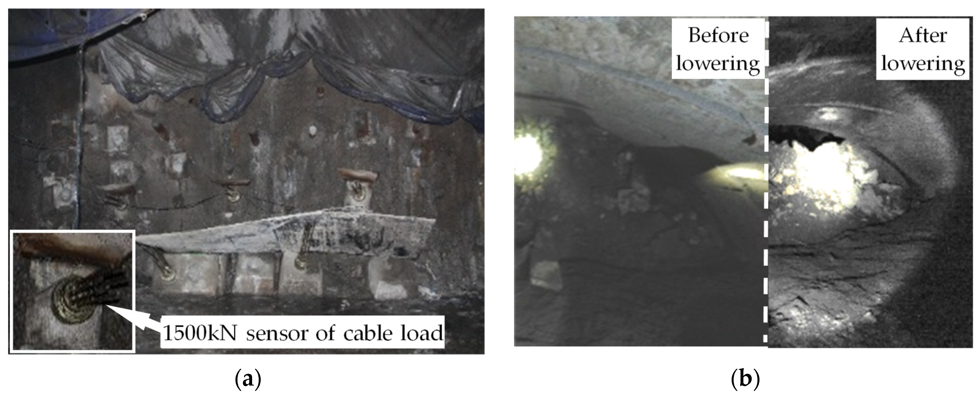
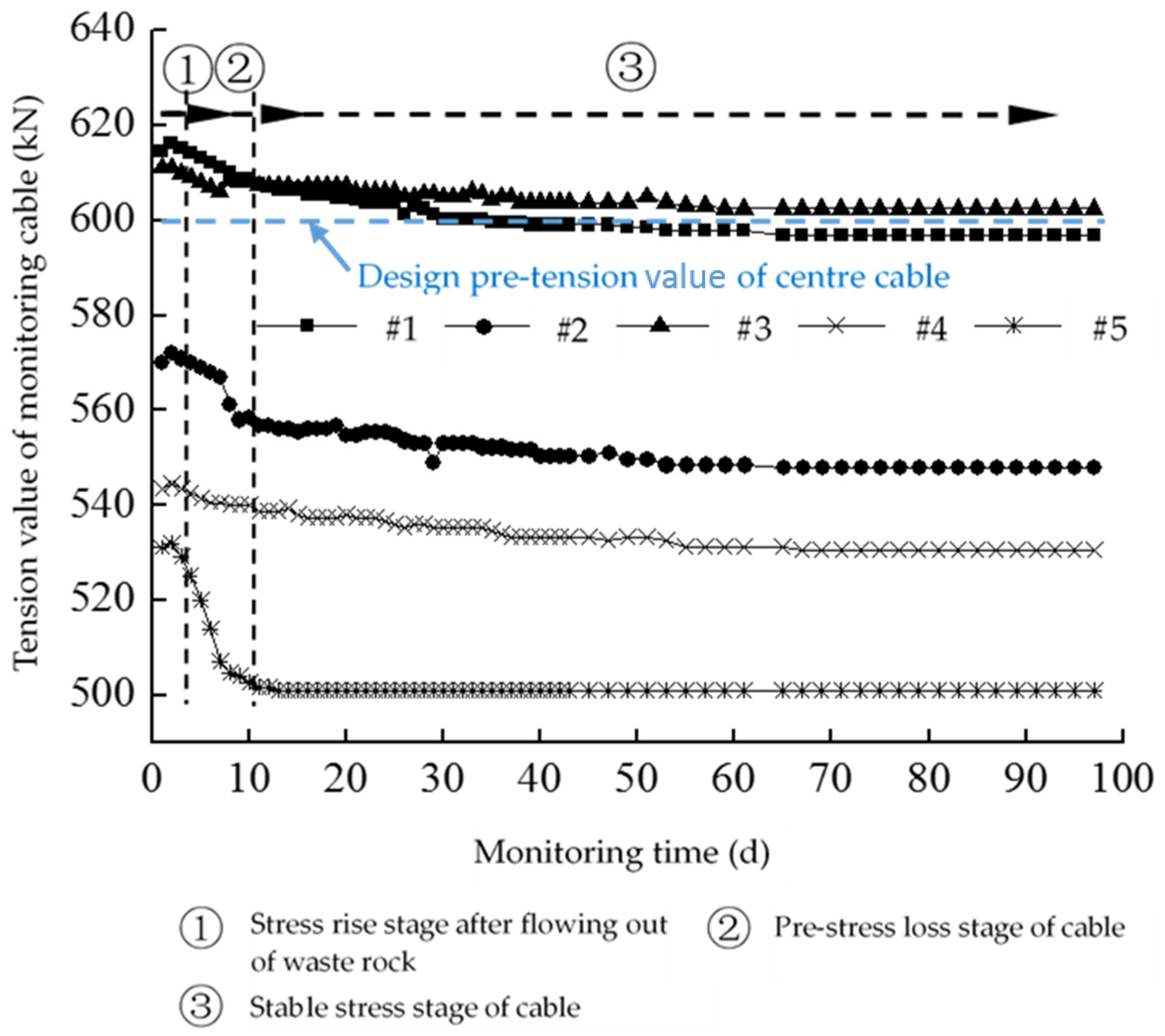
It can be seen from Figure 13 that after waste rocks below the plugging structure are lowered, the incline of the ore pass is immediately exposed and the plugging structure is kept stable. It indicates that the overall design and construction fully meet the requirements of use, waste rocks are lowered once, and the lower part below the main ore pass is not blocked. Within three months after the engineering is completed, persistent data monitoring of cable load sensors show that the entire plugging structure is stable (Figure 14).
In summary, for the plugging technology used in the extensively collapsed ore pass in the non-empty condition, the entire design and construction is scientific and reasonable, which has met the use requirements for the main ore pass and achieved the expected effects.
5. Conclusions
This paper presents a structure-plugging system and its key technology integration for the extensively collapsed long ore pass, and introduces an application case. Some meaningful conclusions have been obtained and are summarized as follows:
- Aiming at a relatively difficult problem such as plugging for the extensively collapsed long ore pass, some simple fundamentals in our daily life such as plug effect, suspension effect, arch effect, and span-reducing effect are ingeniously combined together and used for the design of the plugging structure. It can be seen that one of the above effects plays a role of little importance in the plugging design; however, the combination of the above effects shows great power to solve extraordinary difficulty.
- A new composite bar combined casing with prestressed cable is created and used in the permanent plugging structure, which includes a series of improvements such as holes and grout vents in the casing body. Meanwhile, an attempt that uses C–S grout for loose rock mass has been finished successfully, in which diffusion characteristics of the C–S grout and grouting method are elaborated in detail.
- Although this structure-plugging system and its key technology has been used successfully in the case of the Xingshan Iron Mine in China, whether the design concept is optimized is still worthy of discussing. Hang-up phenomena often happen in many large ore passes, and this situation seems to occur easily and frequently because several blocks could remain stable enough to bear vertical pressure for a long time. So, some considerations and efforts should be gradually taken and optimized to near the hang-up state in the plugging design in the future.
6. Patents
He Chen; Hui Cao; Shibo Yu; et al. Plugging Method for Main Ore Pass. CHN. Patent 201610648910.X, 9 August 2016.
Shibo Yu; Hui Cao; et al. Anti-jam Stem and Drill for DTH. CHN. Patent 201620863850.9, 10 August 2016.
Hui Cao; Shibo Yu; et al. Grouting Reinforcement Method for Inhomogeneous Loose Rock Mass. CHN. Patent 201610648894.4, 9 August 2016.
Shibo Yu; Hui Cao; et al. Accurate Simultaneous Casing Drilling Control Method for Compsite Rock Mass. CHN. Patent 201610648801.8, 9 August 2016.
Author Contributions
H.C. conceived and designed the main ideas proposed in the paper. S.Y. wrote the paper, and also designed and performed the demonstrations of this technology. Z.W. finished compiling a collection of data in the field. Y.Y. designed the experiments of controllable grouting.
Funding
This work is financially supported by the National Natural Science Foundation of China (No. 41602365), State Key Research Development Program of China (No. 2017YFC0602904; No. 2016YFC0600709) and the International S&T Cooperation Program of China (No. 2015DFR70880).
Acknowledgments
This work is supported friendly by the Xingshan Iron Mine, especially Baogang Zhang, Jizhong Zhao, Xinming Li, Chen Guo, Jun Gao, Jiaying Wei and other related engineers. The authors are grateful for their support.
Conflicts of Interest
The authors declare no conflict of interest.
References
- Gardner, L.J.; Fernandes, N.D. Ore pass rehabilitation–case studies from impala platinum limited. J. S. Afr. Inst. Min. Met. 2006, 106, 17–23. [Google Scholar]
- Yu, S.B.; Being General Research Institue of Mining & Metallurgy, Beijing, China; Yuan, Y.; Being General Research Institue of Mining & Metallurgy, Beijing, China. Research on a key technique of pluging of main ore pass in Xingshan Irion Mine. Personal communication, 2016. [Google Scholar]
- Guo, C.; Xu, S.L. Exploration and practice of the landslide area solution at −330 m level ore dumping chamber and the main ore pass in Xingshan iron ore mine. Chin. Min. 2017, 26, 171–174. [Google Scholar]
- Gao, Y.T.; Wang, J.; Song, W.D.; Wu, S.C. A new technique—Supporting funnel method used in recovering and controlling of large-scale collapsed main ransportation shaft. Chin. J. Rock Mech. Eng. 2002, 22, 540–545. [Google Scholar]
- Hadjigeorgiou, J.; Lessard, J.F. Numerical investigations of ore pass hang-up phenomena. Int. J. Rock Mech. Min. Sci. 2007, 44, 820–834. [Google Scholar] [CrossRef]
- Hadjigeorgiou, J.; Lessard, J.F. Strategies for restoring material flow in ore and waste pass systems. Int. J. Min. Reclam. Environ. 2010, 24, 267–282. [Google Scholar] [CrossRef]
- Thanh, V.; Yang, H.W.; Adrian, R.R. Cohesion and suction induced hang-up in ore passes. Int. J. Rock Mech. Min. Sci. 2016, 87, 113–128. [Google Scholar]
- Hadjigeorgiou, J.; Mercier-Langevin, F. Estimating ore pass longevity in hard rock mines. In Proceedings of the 42nd US Rock Mechanics Symposium, San Francisco, CA, USA, 29 June–2 July 2008. [Google Scholar]
- Clegg, I.D.; Hanson, D.S. Ore pass design and support at Falconbridge Limited. In Proceedings of the International Symposium on Rock Support, Sudbury, ON, Canada, 16–19 June 1992. [Google Scholar]
- Hadjigeorgiou, J.; Esmaieli, K. Selecting ore pass–finger raise configurations in underground mines. Rock Mech. Rock Eng. 2011, 44, 291–303. [Google Scholar]
- Hadjigeorgiou, J.; Lessard, J.F.; Mercier-Langevin, F. Ore pass practice in Canadian mines. J. S. Afr. Inst. Min. Met. 2005, 105, 809–816. [Google Scholar]
- Luo, Z.Q.; Chen, J.; Xie, C.Y.; Wang, W.; Liu, X.M. Mechanism of impact-induced damage of main ore pass and its experimental validation. Rock Soil Mech. 2015, 36, 1744–1751. [Google Scholar]
- Esmaieli, K.; Hadjigeorgiou, J.; Grenon, M. Stability analysis of the 19A ore pass at Brunswick mine using a two-stage numerical modeling approach. Rock Mech. Rock Eng. 2013, 46, 1323–1338. [Google Scholar] [CrossRef]
- Song, W.D.; Wang, H.Y.; Wang, X.; Wang, W.; Du, J.H. Theoretical analysis and test of impact load due to ore dumping in chute. Rock Soil Mech. 2011, 32, 326–332. [Google Scholar]
- Zhao, Y.; Ye, H.W.; Lei, T.; Wang, C.; Wang, Q.Z.; Long, M. Theoretical study of damage characteristics on ore pass wall based on the erosion-wearing theory. Chin. J. Rock Mech. Eng. 2017, 36, 4002–4007. [Google Scholar]
- Li, C.H.; Cai, M.F.; Qiao, L.; Ji, H.G.; Liu, G.F.; Wang, J.B.; Zhao, K.G.; Liu, Y.S. Engineering design and construction effect of reinforcement measures of main ore pass. Mine Constr. Tech. 1999, 20, 21–23. [Google Scholar]
- Alex, M.R.; Verne, M.; Sanjay, N.; Ting, R. Experimental and numerical investigation of high-yield grout ore pass plugs to resist impact loads. Int. J. Rock Mech. Min. Sci. 2014, 70, 1–15. [Google Scholar]
- Carr, C.J.; Krause, L.E. Ore pass and chute maintenance at Xstrata–Mount Isa Copper Operations. In Proceedings of the 9th AusIMM Underground Operators’ Conference, Perth, Australia, 7–9 March 2005. [Google Scholar]
- Jin, C.Y.; Jin, Q.; Jiang, Q. Pressure variation at ore pass bottom during ore drawing process. J. Northeast. Univ. Nat. Sci. 2012, 33, 887–890. [Google Scholar]
- China Coal Construction Association. Code for Design of Reinforced Congcrete Silos, GB50077-2003; China Planning Press: Beijing, China, 2004; pp. 15–20. ISBN 1580058-543. [Google Scholar]
- Di, M.K. Research on ore movement in ore pass draft (two eights). Foreign Met. Mine 1990, 9, 35–39. [Google Scholar]
- Yu, S.B.; Chen, H.; Cao, H.; Yuan, Y.; Zhao, J.Z.; Guo, C. Analysis and engineering application of blocking pressure of ore pass. Chin. Min. Mag. 2016, 25, 299–302. [Google Scholar]
- Wang, Y.M. Modern Mine Manual, 1st ed.; Metallurgical Industry Press: Beijing, China, 2011; pp. 600–605. ISBN 978-7-5024-5567-5. [Google Scholar]
- Yu, S.B.; Yang, X.C.; Dong, K.C.; Xie, L.K.; Sun, X.M.; Guo, L.J. Space-time rule of the control action of filling body for the movement of surrounding rock in method of the delayed filling open stoping. J. Min. Saf. Eng. 2014, 31, 430–434. [Google Scholar]
- Evert, H.; Antonio, K. Rock-mass properties for surface mines. In Slope Stability in Surface Mining; William, A.H., Michael, K.M., Dirk, J.A., Van, Z., Eds.; Society for Mining, Metallurgy, and Exploration, Inc.: Littleton, CO, USA, 2009; pp. 59–67. ISBN 978-0-87335-295-6. [Google Scholar]
- Cai, M.F. Mechanics and Engineering of Rock, 1st ed.; Science Press: Beijing, China, 2002; pp. 104–108. ISBN 978-7-03-010470-0. [Google Scholar]
- Ministry of Construction of the People’s Republic of China. Code for Design of Steel Structures, GB50017-2003; China Planning Press: Beijing, China, 2003; pp. 8–10. ISBN 1580058-536.
- Evert, H. Rock mass properties for underground mines. In Underground Mining Methods–Engineering Fundamentals and International Case Studies; William, A.H., Richard, L.B., Eds.; Society for Mining, Metallurgy, and Exploration, Inc.: Littleton, CO, USA, 2001; pp. 467–474. ISBN 0-87335-193-2. [Google Scholar]
- Zhou, X.; Gao, G.R. Grouting Construction Manual, 1st ed.; China Coal Industry Press: Beijing, China, 2014; pp. 52–58. ISBN 978-7-5020-4405-3. [Google Scholar]
- Ma, G.Y.; Chang, Z.H. Theory and Practice of Grouting Drainage and Anchorage of Rock Mass, 1st ed.; China Water Publisher: Beijing, China, 2003; pp. 64–71. ISBN 7-5084-1458-6. [Google Scholar]
- Ruan, W.J. Spreading model of grouting in rock mass fissures based on time-dependent behavior of viscosity of cement-based grouts. Chin. J. Rock Mech. Eng. 2005, 24, 2709–2714. [Google Scholar]
- Li, S.C.; Liu, R.T.; Zhang, Q.S.; Sun, Z.Z.; Zhang, X.; Zhu, M.T. Research on C-S slurry diffusion mechanism with time-dependent behavior of viscosity. Chin. J. Rock Mech. Eng. 2013, 32, 2415–2421. [Google Scholar]
- Zhang, F.M.; Pan, X.; Chang, L.Y. Mine Design Manual; Sinking and Driving Engineering Volume; China Architecture & Building Press: Beijing, China, 1989; pp. 536–537. ISBN 7-112-00445-4/TD-5. [Google Scholar]
Figure 1.
Structure-plugging system for an ore pass in the non-empty condition.
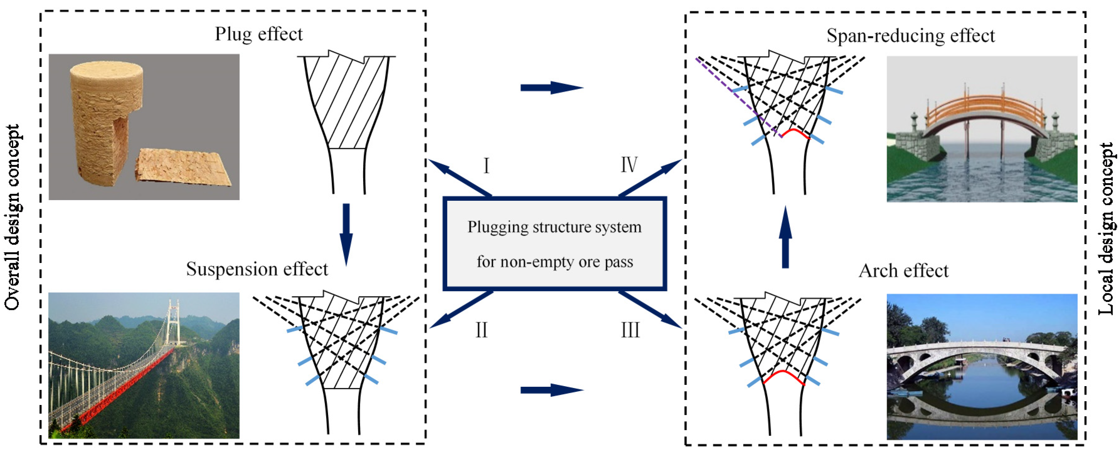
Figure 2.
Mechanical models of shear failure of a plugging structure.

Figure 3.
Technical difficulties in the process of drilling with casing in the composite rock mass.

Figure 4.
Arrangement parameters of holes in the body of the drill rod to prevent sticking. DTH: down-the-hole drill.
Figure 4.
Arrangement parameters of holes in the body of the drill rod to prevent sticking. DTH: down-the-hole drill.
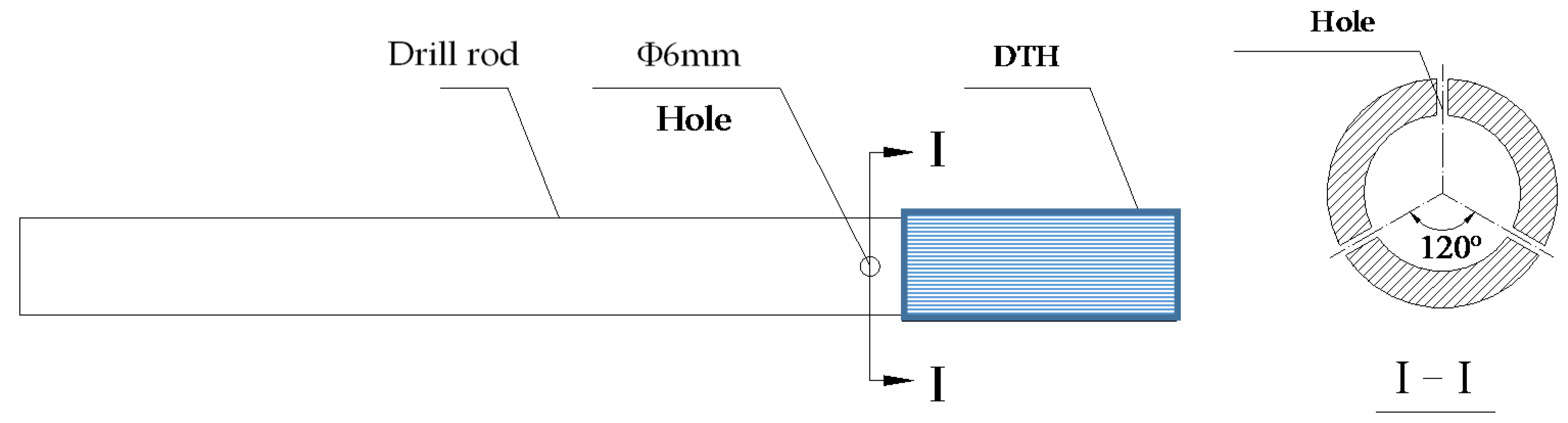
Figure 5.
Arrangement parameters of grout vents in the body of the casing.
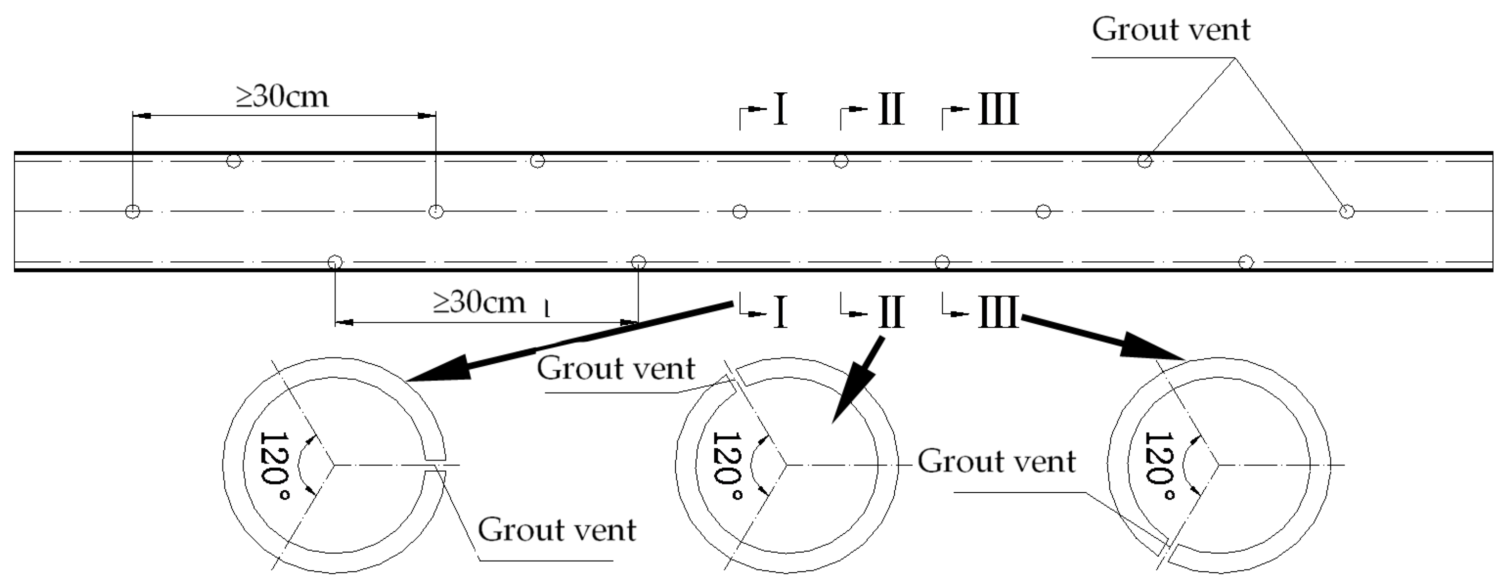
Figure 6.
Concretion of C–S grout in the seemingly homogeneous loose rock mass (setting time: 18 s): (a) Vertical direction; (b) Horizontal direction.
Figure 6.
Concretion of C–S grout in the seemingly homogeneous loose rock mass (setting time: 18 s): (a) Vertical direction; (b) Horizontal direction.
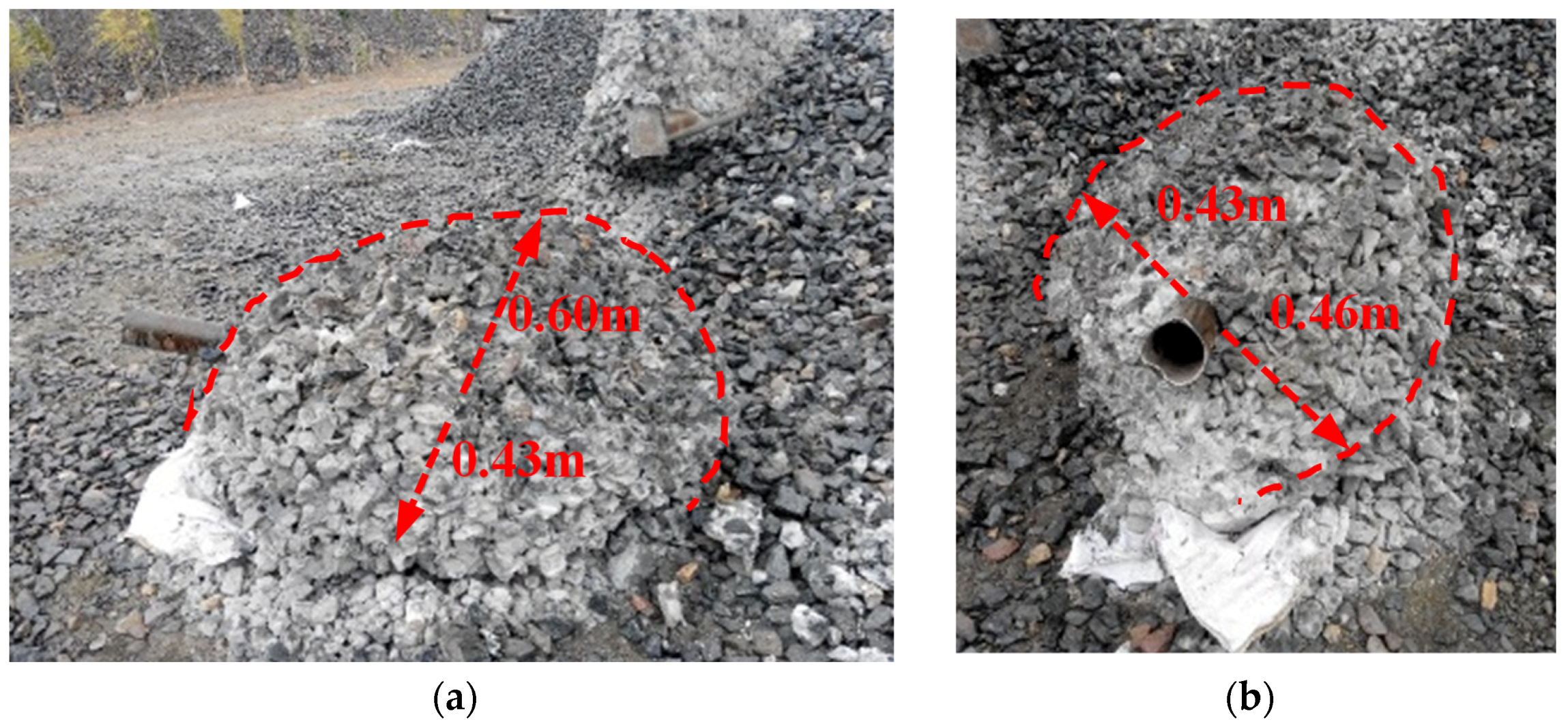
Figure 7.
Relationship of setting time–vertical diffusion distance of C–S grout in the loose rock mass. W/C: water cement ratio; Vs/Vc: volume ratio of sodium silicate to cement slurry.
Figure 7.
Relationship of setting time–vertical diffusion distance of C–S grout in the loose rock mass. W/C: water cement ratio; Vs/Vc: volume ratio of sodium silicate to cement slurry.
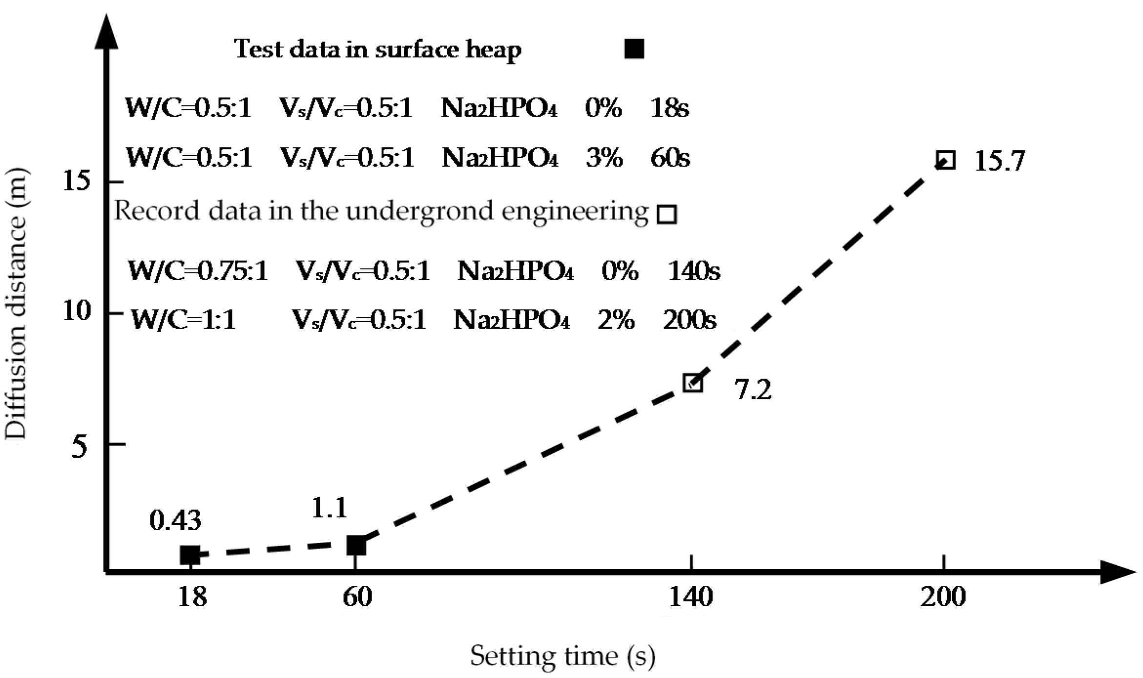
Figure 8.
Implementation process and method of controllable grouting for inhomogeneous loose rock mass.
Figure 8.
Implementation process and method of controllable grouting for inhomogeneous loose rock mass.

Figure 9.
Location plan of the main ore pass.

Figure 10.
Collapse shapes of the main ore pass.
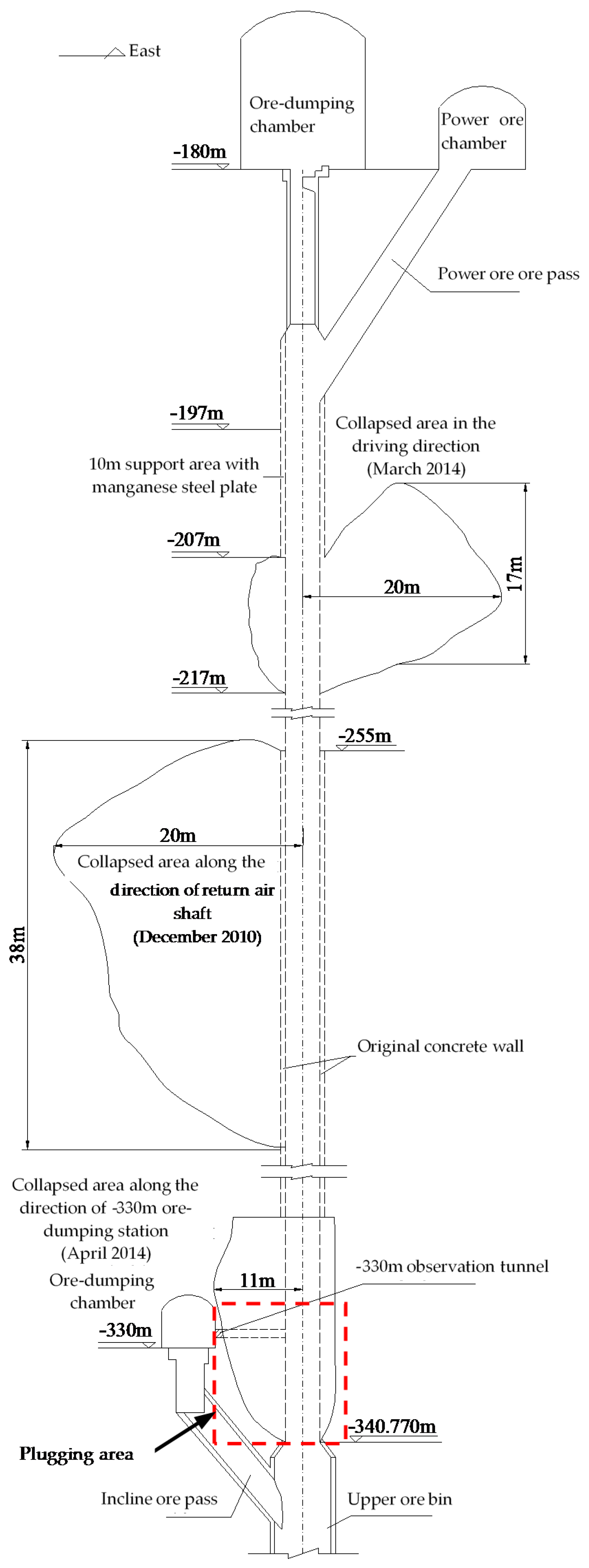
Figure 11.
The design heights and safety factors of the plugging structure corresponding to different calculation methods of vertical stress.
Figure 11.
The design heights and safety factors of the plugging structure corresponding to different calculation methods of vertical stress.
Figure 12.
Plugging design of the main ore pass.
Figure 13.
Plugging effect of the main ore pass: (a) Whole picture of plugging engineering; (b) Before and after ore lowering in the incline ore pass.
Figure 13.
Plugging effect of the main ore pass: (a) Whole picture of plugging engineering; (b) Before and after ore lowering in the incline ore pass.

Figure 14.
Tension-time curve of monitoring cable.

© 2018 by the authors. Licensee MDPI, Basel, Switzerland. This article is an open access article distributed under the terms and conditions of the Creative Commons Attribution (CC BY) license (http://creativecommons.org/licenses/by/4.0/).
Share and Cite
MDPI and ACS Style
Chen, H.; Yu, S.; Wang, Z.; Yuan, Y. A New Plugging Technology and Its Application for the Extensively Collapsed Ore Pass in the Non-Empty Condition. Energies 2018, 11, 1599. https://doi.org/10.3390/en11061599
AMA Style
Chen H, Yu S, Wang Z, Yuan Y. A New Plugging Technology and Its Application for the Extensively Collapsed Ore Pass in the Non-Empty Condition. Energies. 2018; 11(6):1599. https://doi.org/10.3390/en11061599
Chicago/Turabian StyleChen, He, Shibo Yu, Zhixiu Wang, and Ye Yuan. 2018. "A New Plugging Technology and Its Application for the Extensively Collapsed Ore Pass in the Non-Empty Condition" Energies 11, no. 6: 1599. https://doi.org/10.3390/en11061599
Note that from the first issue of 2016, this journal uses article numbers instead of page numbers. See further details here.