Gain Scheduled Torque Compensation of PMSG-Based Wind Turbine for Frequency Regulation in an Isolated Grid

 , ,
, ,
Abstract
:1. Introduction
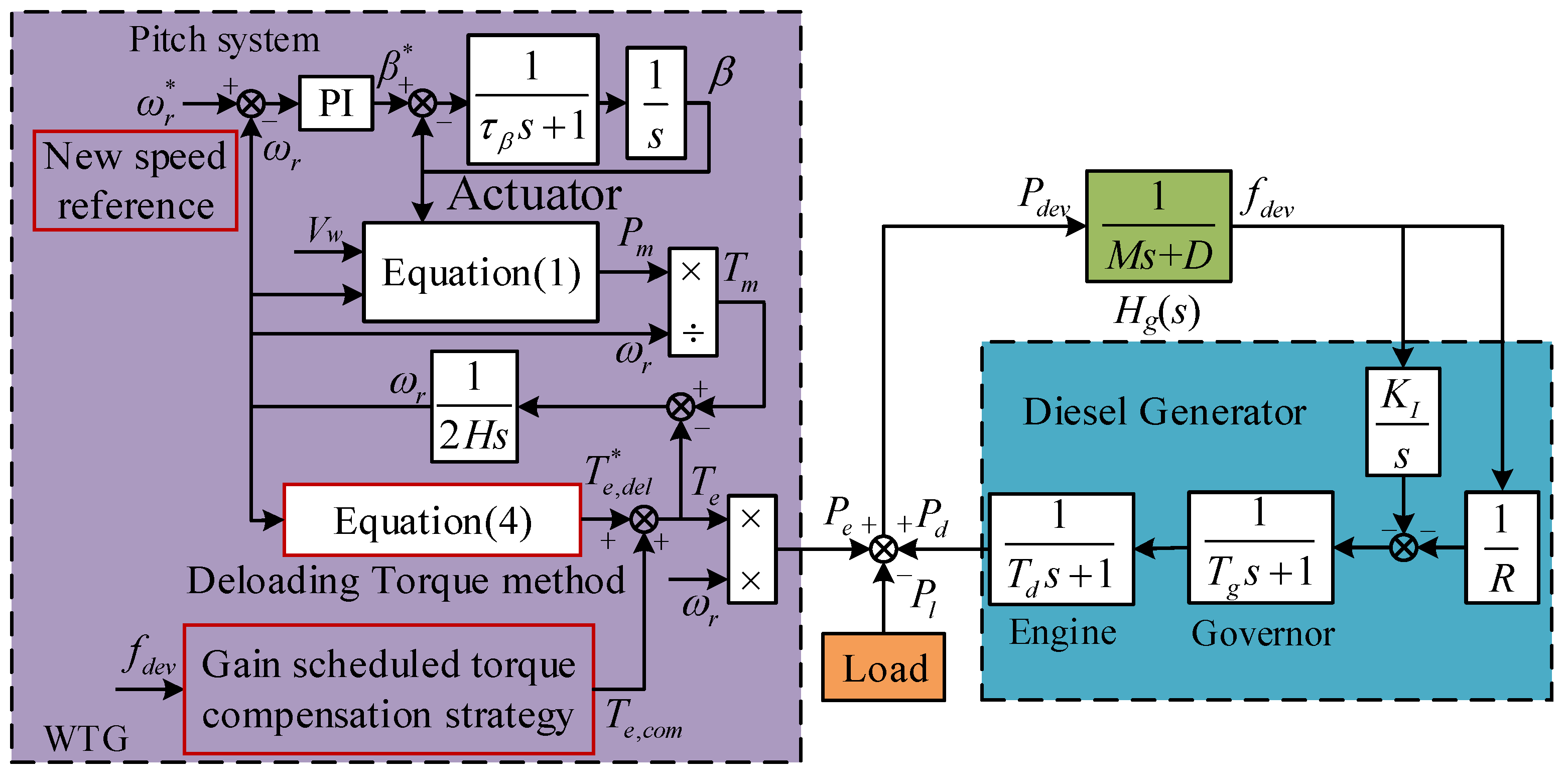
- To optimize the primary frequency contribution of WTG, this paper presents a gain scheduled control strategy based on H∞ theory which combines the advantages of steady-state power reserves and inertia and enhances the torque compensation gain at whole range of wind speed.
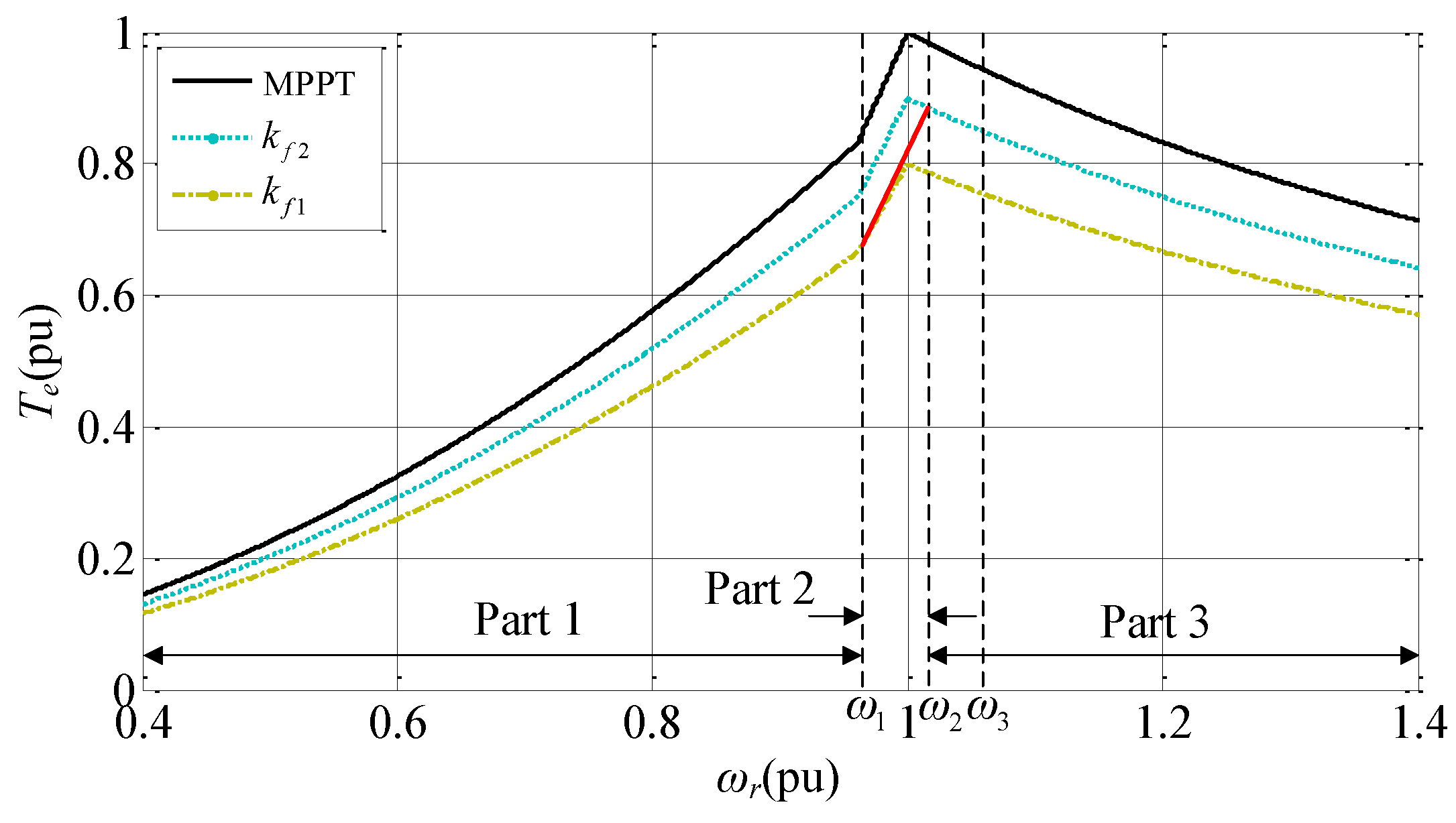
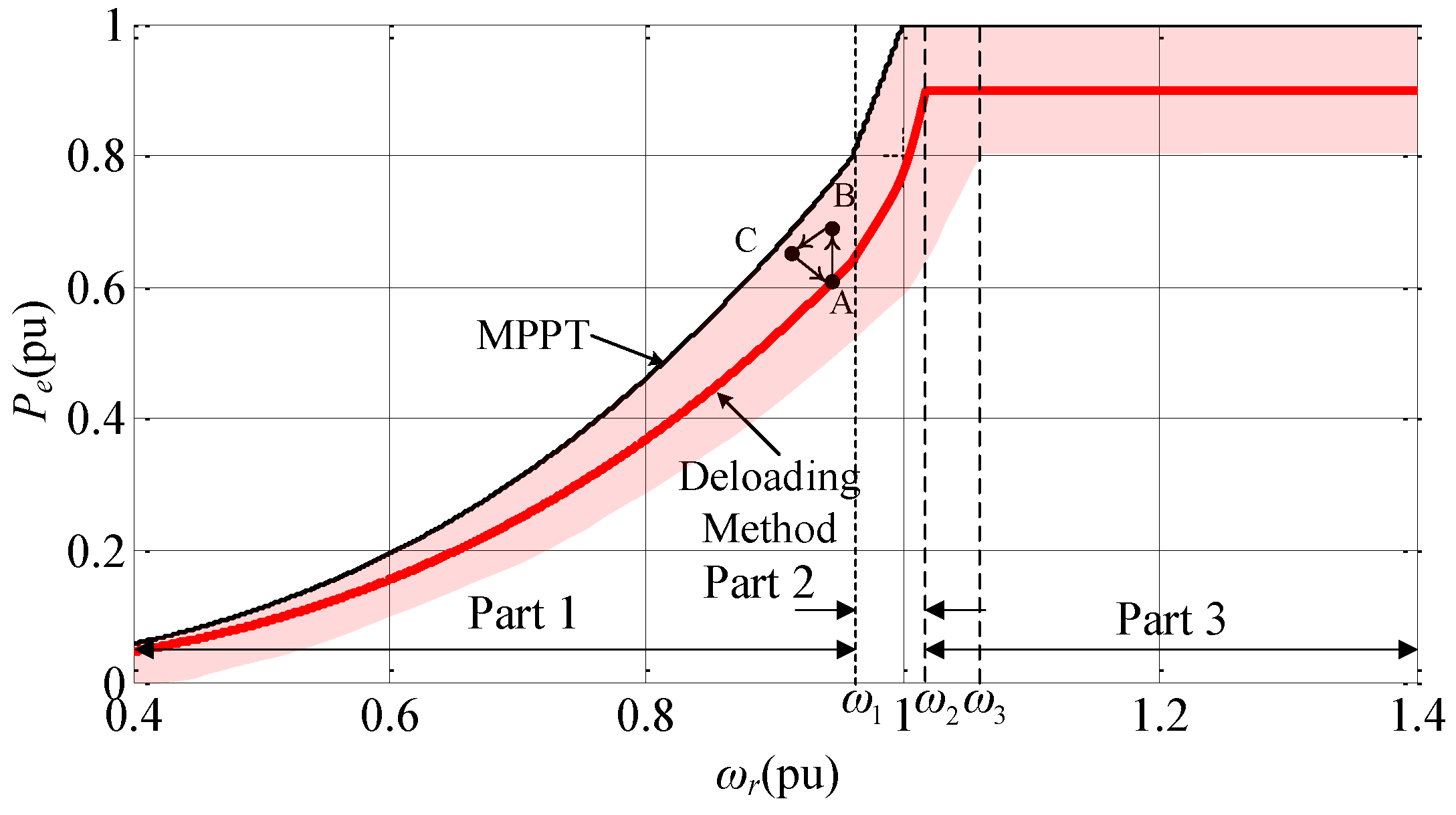
- In the deloading method, different deloading factors are designed to smoothen WTG output power and to ensure more power reserve.
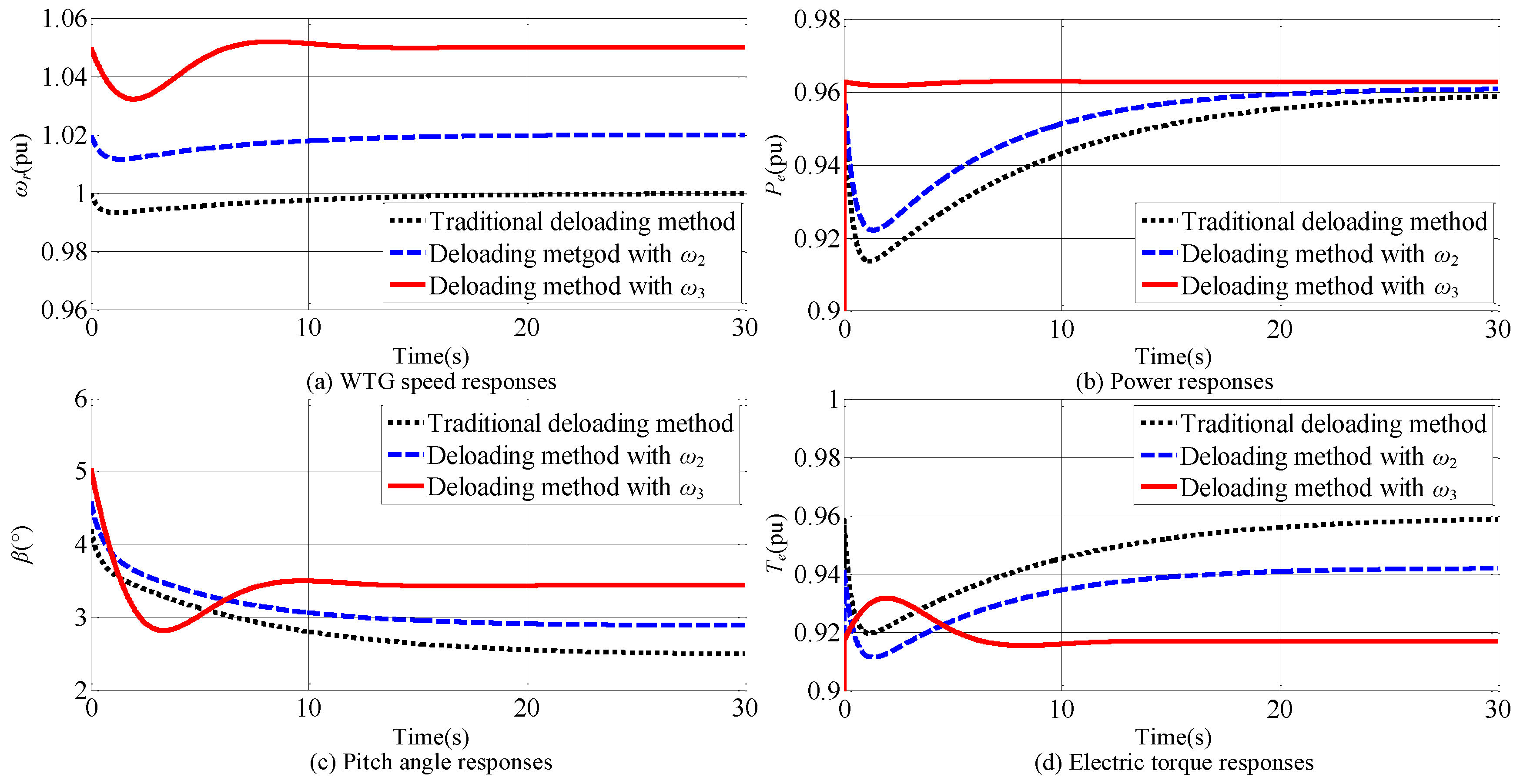
- The WTG speed reference of pitch control system is changed to avoid decay or even power oscillation between different Speed Parts caused by torque compensation.
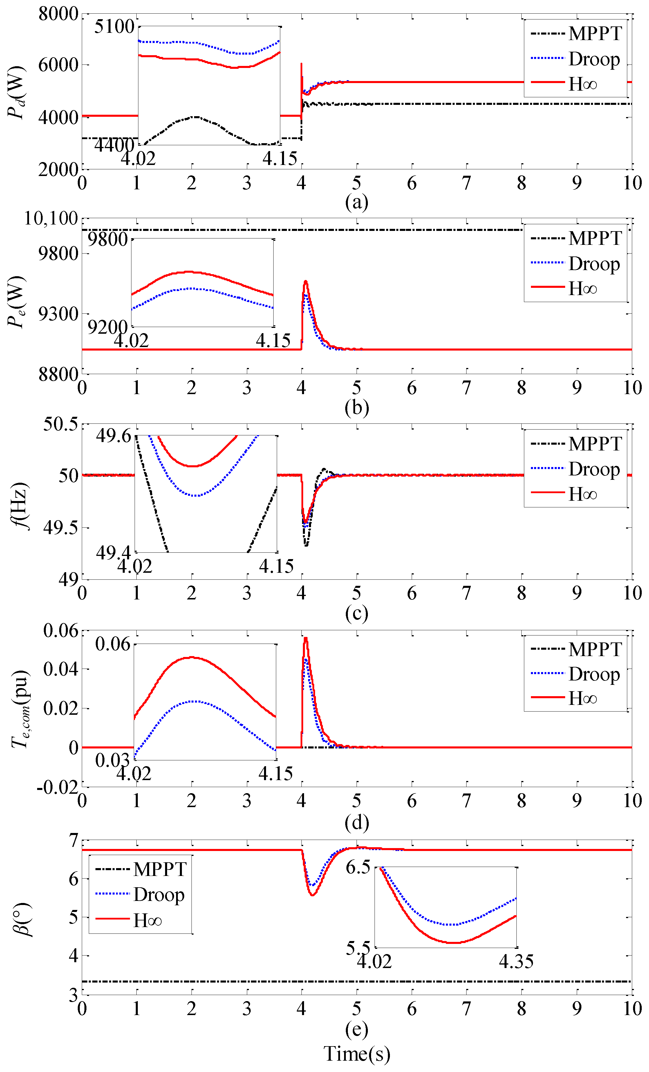
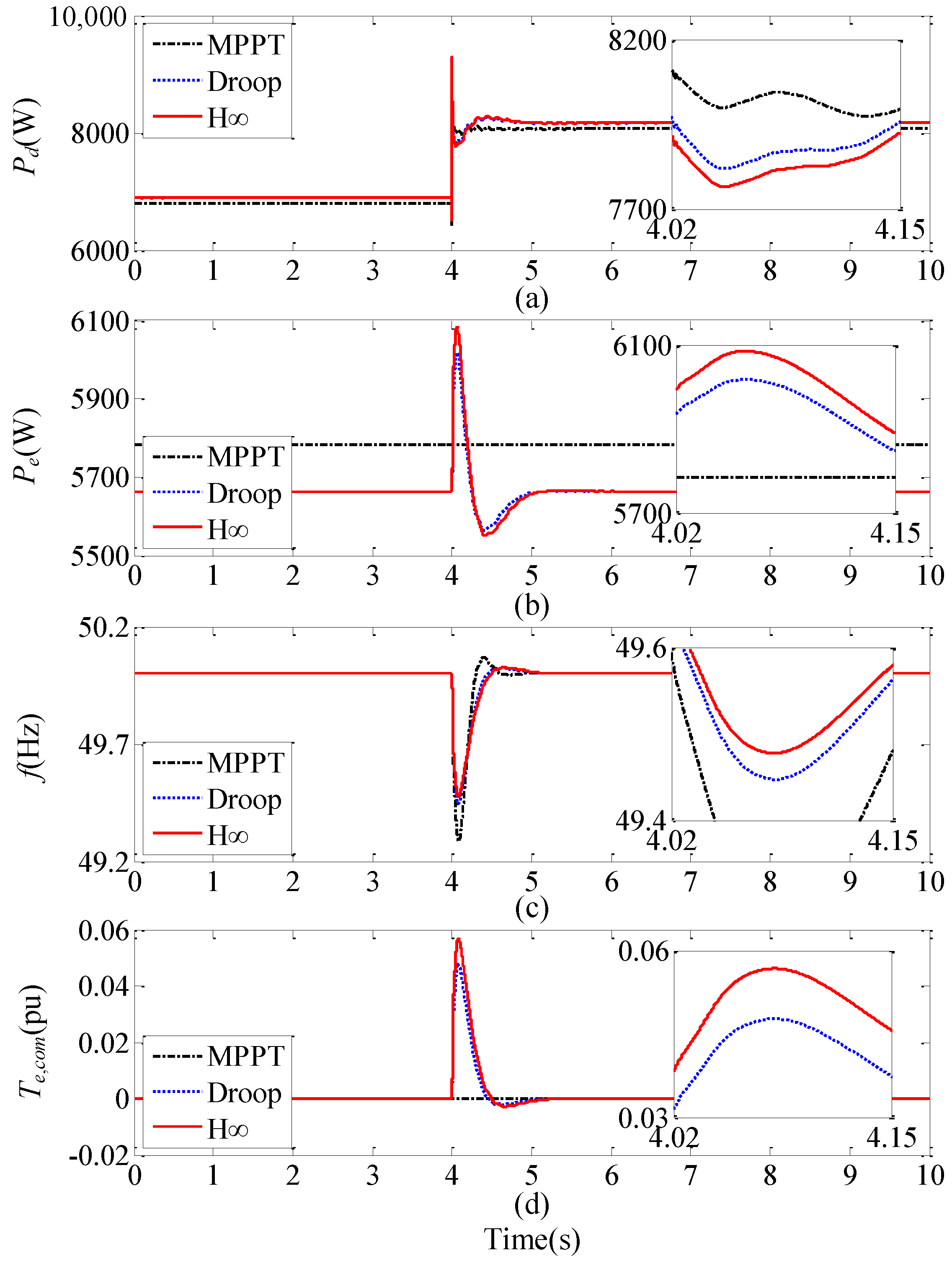
- Comparing with the state-of-the-art MPPT and Droop methods, the frequency deviation with the proposed strategy is reduced by 0.16 Hz and 0.04 Hz, respectively, at over-rated wind speed, and 0.38 Hz and 0.06 Hz, respectively, when wind speed changes.
2. Isolated Grid Configuration
3. Deloading Method for WTG
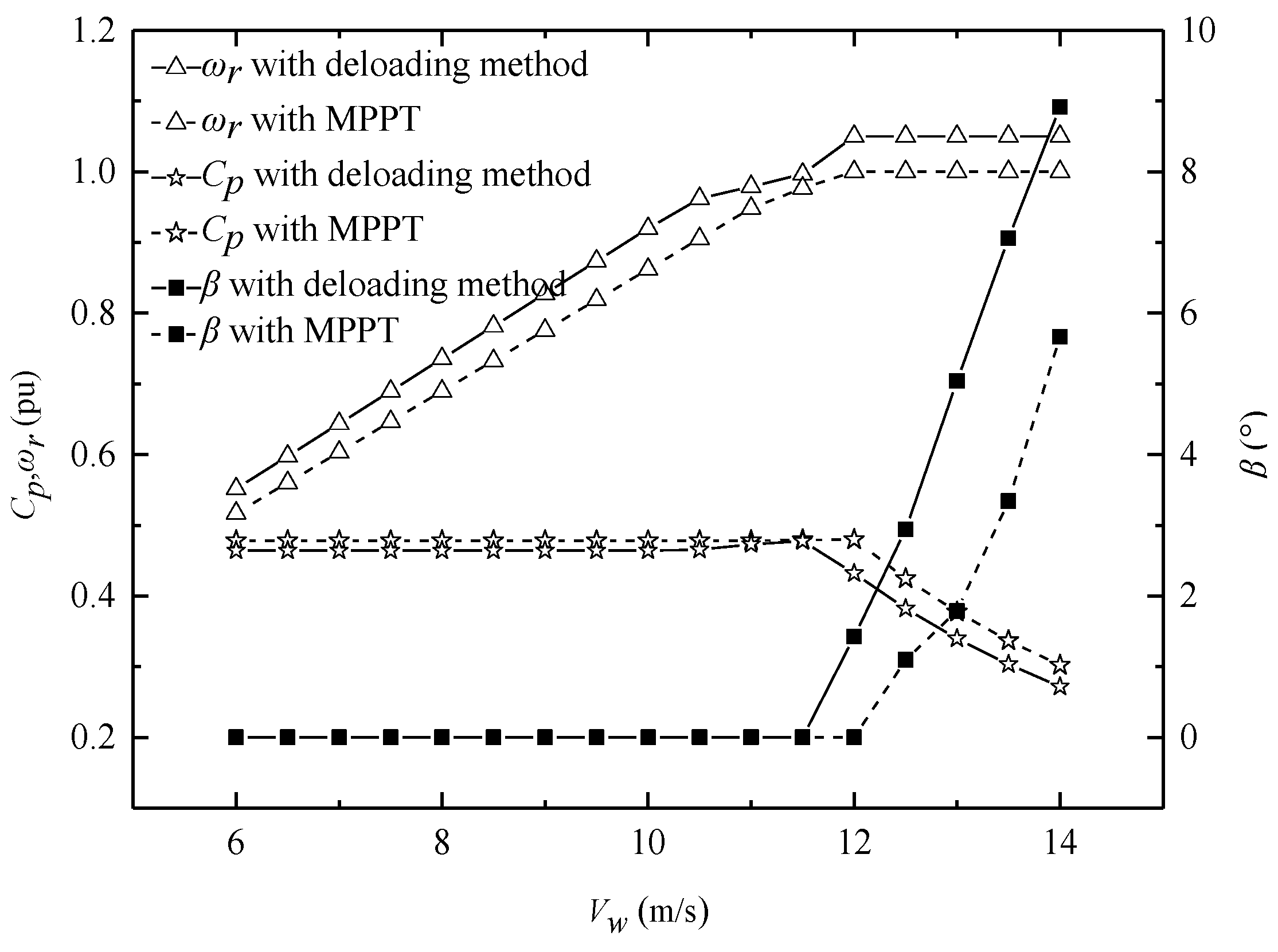
4. Analysis of Deloaded WTG
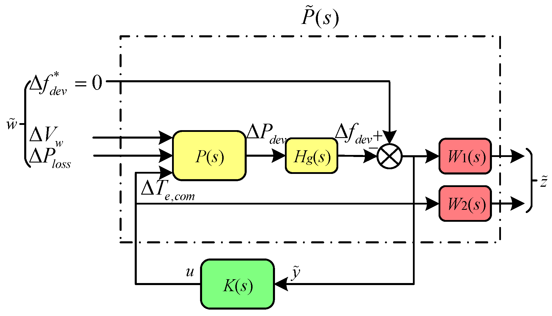
5. Design of Torque Compensation Controller
5.1. Linearized Models of the Deloaded WTG
5.2. Design of Gain Scheduled Torque Compensation Controller
6. Simulation and Experiment
6.1. Simulation Setup
6.2. Simulation Results
6.2.1. Case 1: At Over-Rated Wind Speed
6.2.2. Case 2: At Under-Rated Wind Speed
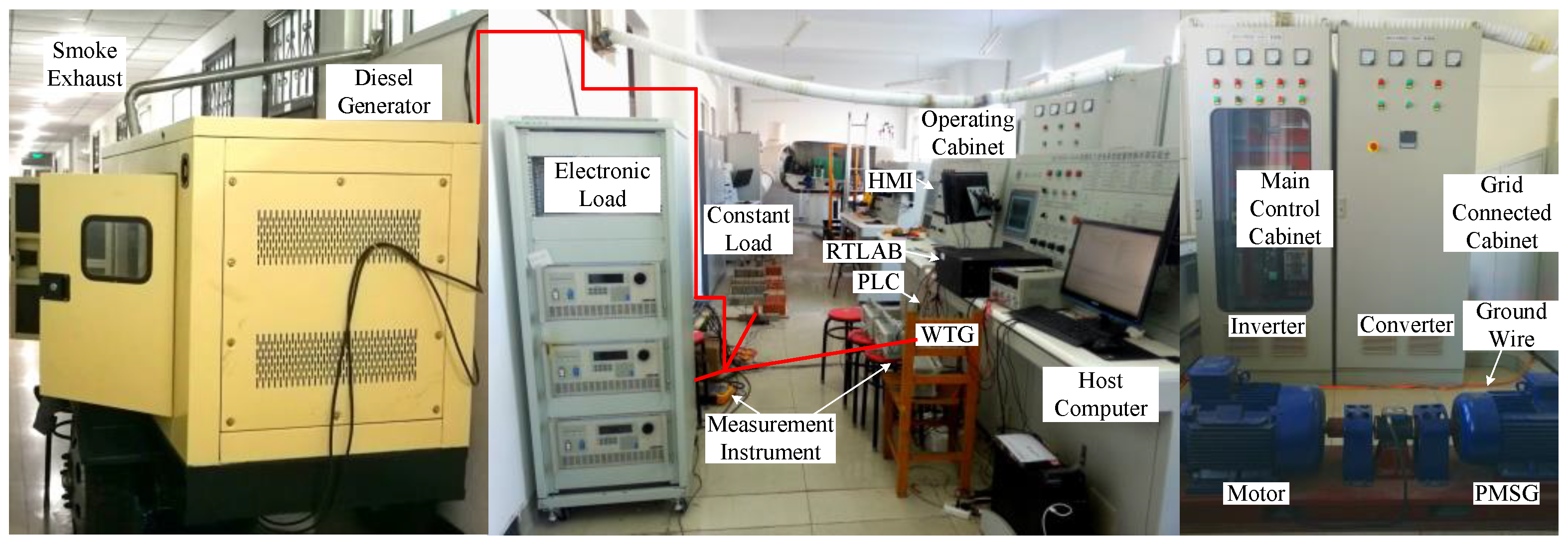
6.3. Experimental Setup
6.4. Experimental Results
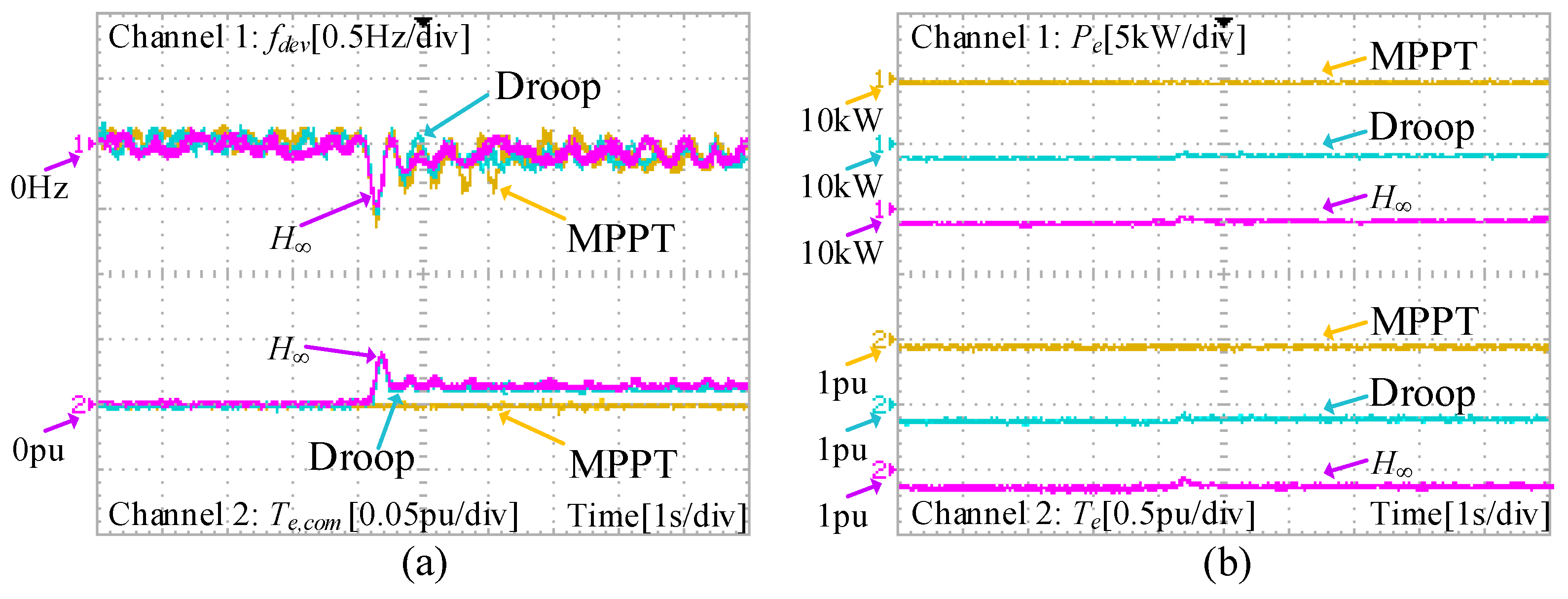
6.4.1. Case 1: At Over-Rated Wind Speed
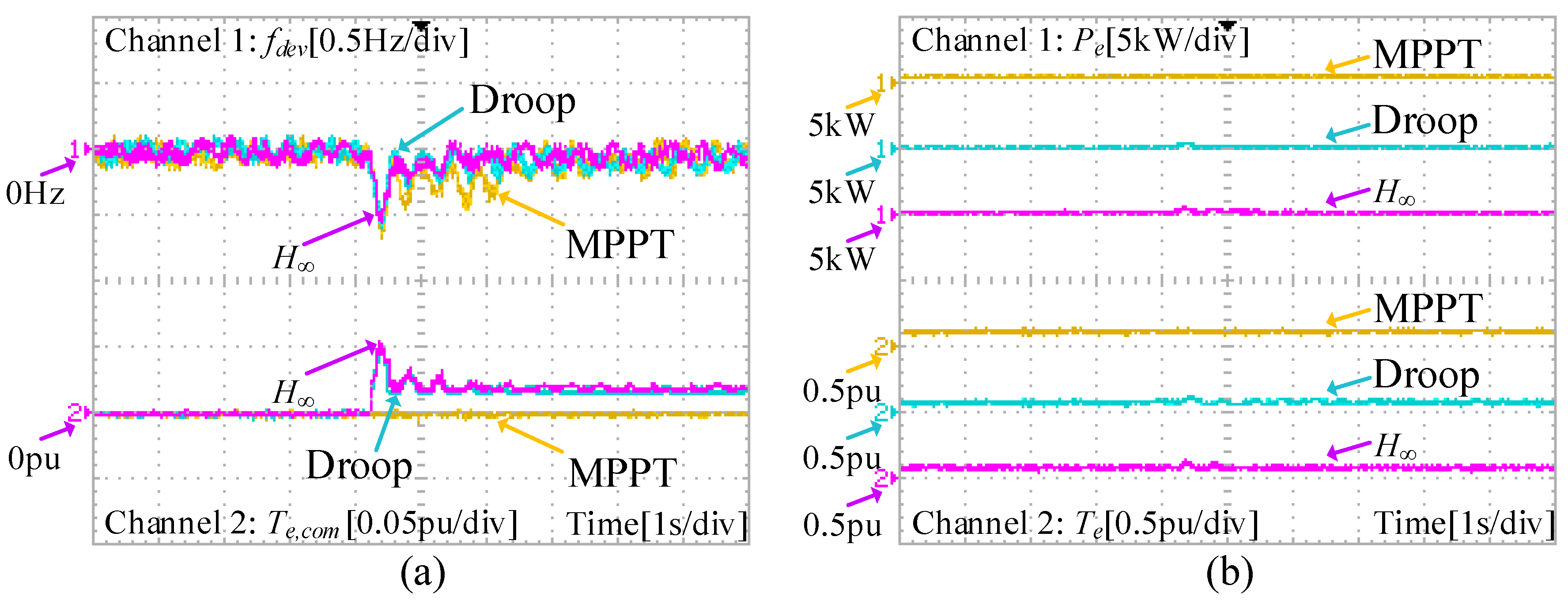
6.4.2. Case 2: At Under-Rated Wind Speed
6.4.3. Summary of Results
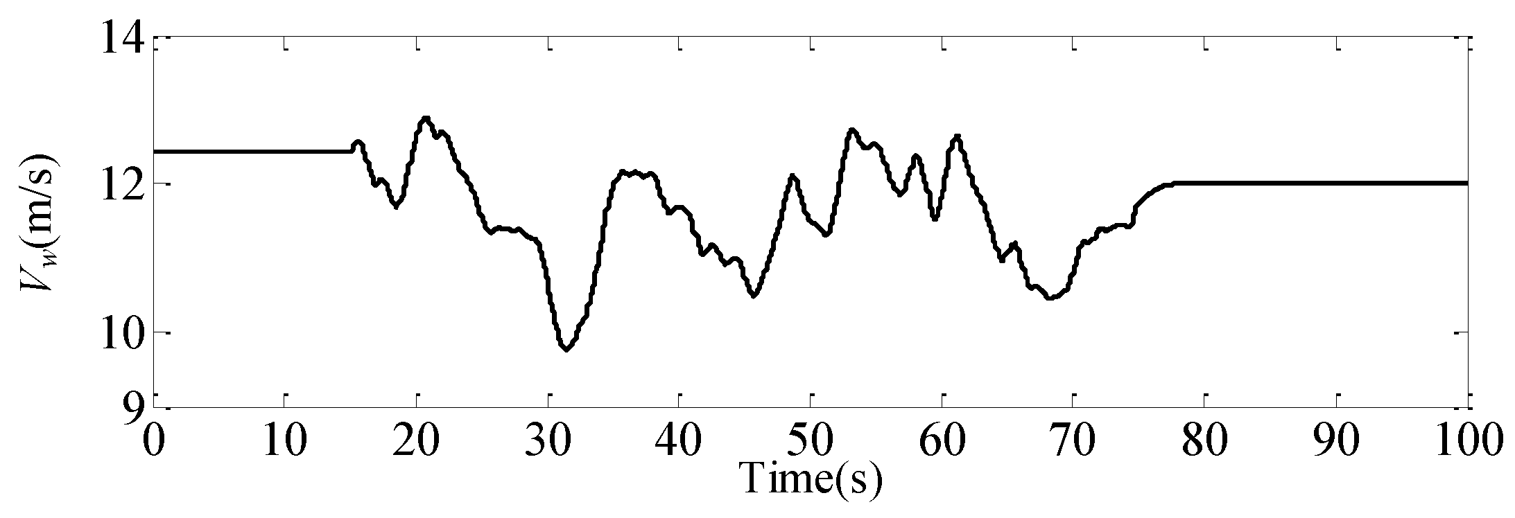
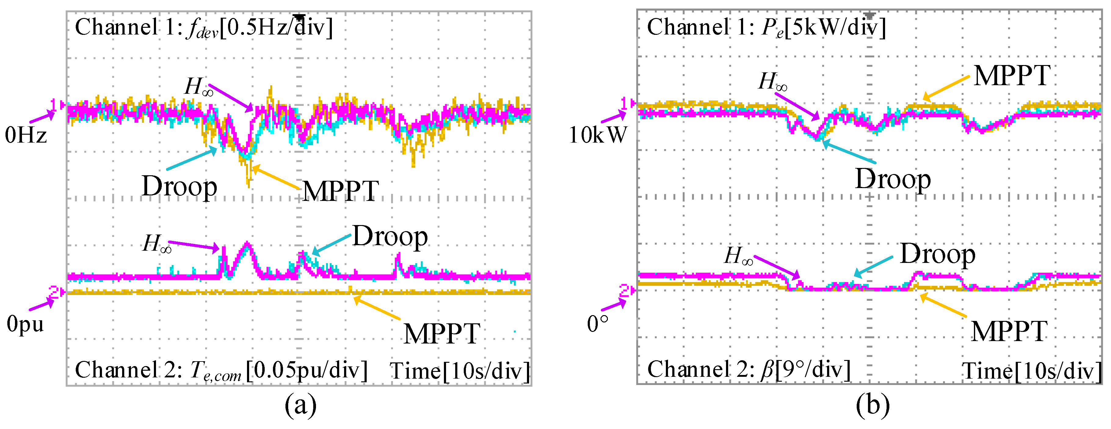
6.4.4. Case 3: Wind Speed Change
7. Conclusions
Author Contributions
Funding
Conflicts of Interest
Appendix A

| c1 | 0.5176 | c2 | 116 | c3 | 0.4 | c4 | 5 |
| c5 | 21 | c6 | 0.0068 | Ar | 20.1 m2 | kopt | 0.1767 |
| kf1 | 0.9 | kf2 | 0.8 | ω0 | 0.4 | ω1 | 0.97 |
| ωr,nom | 1 | ω2 | 1.02 | ω3 | 1.05 | ωr,max | 1.2 |
| R | 0.08 | KI | 7 |
| Td | 0.005 s | Tg | 0.1 s |
| M | 0.5 | D | 0.01 |
| ωr0 | 34.2927 rad/s | a1 | 0 |
| a2 | 78.4096 | a3 | 1979.1 |
| ωr0 | 40.32 rad/s | a1 | −437.7964 |
| a2 | 101.5045 | a3 | 1696.9 |
References
- Attya, A.B.; Dominguez-Garcia, J.L.; Anaya-Lara, O. A review on frequency support provision by wind power plants: Current and future challenges. Renew. Sustain. Energy Rev. 2018, 81, 2071–2087. [Google Scholar] [CrossRef]
- Pradhan, C.; Bhende, C.N.; Samanta, A.K. Adaptive virtual inertia-based frequency regulation in wind power systems. Renew. Energy 2018, 115, 558–574. [Google Scholar] [CrossRef]
- Attya, A.B.; Hartkopf, T. Wind turbine contribution in frequency drop mitigation—Modified operation and estimating released supportive energy. IET Gener. Trans. Distrib. 2014, 8, 862–872. [Google Scholar] [CrossRef]
- Wu, Z.; Gao, W.; Gao, T.; Yan, W.; Zhang, H.; Yan, S.; Wang, X. State-of-the-art review on frequency response of wind power plants in power systems. J. Mod. Power Syst. Clean Energy 2018, 6, 1–16. [Google Scholar] [CrossRef]
- Krpan, M.; Kuzle, I. Introducing low-order system frequency response modelling of a future power system with high penetration of wind power plants with frequency support capabilities. IET Renew. Power Gener. 2018, in press. [Google Scholar] [CrossRef]
- Bevrani, H.; Feizi, M.R.; Ataee, S. Robust frequency control in an islanded microgrid: H∞ and μ-synthesis approaches. IEEE Trans. Smart Grid 2016, 7, 706–717. [Google Scholar] [CrossRef]
- Wilches-Bernal, F.; Chow, J.H.; Sanchez-Gasca, J.J. A fundamental study of applying wind turbines for power system frequency control. IEEE Trans. Power Syst. 2016, 31, 1496–1505. [Google Scholar] [CrossRef]
- Nguyen, N.; Mitra, J. An analysis of the effects and dependency of wind power penetration on system frequency regulation. IEEE Trans. Sustain. Energy 2016, 7, 354–363. [Google Scholar] [CrossRef]
- Mitra, A.; Chatterjee, D. Active power control of DFIG-based wind farm for improvement of transient stability of power systems. IEEE Trans. Power Syst. 2016, 31, 82–93. [Google Scholar] [CrossRef]
- Zoghlami, M.; Kadri, A.; Bacha, F. Analysis and application of the sliding mode control approach in the variable-wind speed conversion system for the utility of grid connection. Energies 2018, 11, 720. [Google Scholar] [CrossRef]
- Martínez-Lucas, G.; Sarasúa, J.I.; Sánchez-Fernández, J.A. Frequency regulation of a hybrid wind–hydro power plant in an isolated power system. Energies 2018, 11. [Google Scholar] [CrossRef]
- Rocabert, J.; Luna, A.; Blaabjerg, F.; Rodríguez, P. Control of power converters in AC microgrids. IEEE Trans. Power Electron. 2012, 27, 4734–4749. [Google Scholar] [CrossRef]
- Wang, H.; Chen, Z.; Jiang, Q. Optimal control method for wind farm to support temporary primary frequency control with minimised wind energy cost. IET Renew. Power Gener. 2015, 9, 350–359. [Google Scholar] [CrossRef]
- Ghosh, S.; Kamalasadan, S.; Senroy, N.; Enslin, J. Doubly fed induction generator (DFIG)-based wind farm control framework for primary frequency and inertial response application. IEEE Trans. Power Syst. 2016, 31, 1861–1871. [Google Scholar] [CrossRef]
- Kamel, R.M.; Chaouachi, A.; Nagasaka, K. Three control strategies to improve the microgrid transient dynamic response during isolated mode: A comparative study. IEEE Trans. Ind. Electron. 2013, 60, 1314–1322. [Google Scholar] [CrossRef]
- Pahasa, J.; Ngamroo, I. Coordinated control of wind turbine blade pitch angle and PHEVs using MPCs for load frequency control of microgrid. IEEE Syst. J. 2016, 10, 97–105. [Google Scholar] [CrossRef]
- Hoseinzadeh, B.; Chen, Z. Intelligent load-frequency control contribution of wind turbine in power system stability. In Proceedings of the IEEE EUROCON, Zagreb, Croatia, 1–4 July 2013. [Google Scholar]
- Asensio, A.P.; Gomez, S.A.; Rodriguez-Amenedo, J.L.; Plaza, M.G.; Carrasco, J.E.G.; de las Morenas, J.M.A.M. A voltage and frequency control strategy for stand-alone full converter wind energy conversion systems. Energies 2018, 11, 474. [Google Scholar] [CrossRef]
- Xiong, L.; Li, Y.; Zhu, Y.; Yang, P.; Xu, Z. Coordinated control schemes of super-capacitor and kinetic energy of DFIG for system frequency support. Energies 2017, 11. [Google Scholar] [CrossRef]
- Tang, Y.; Dai, J.; Ning, J.; Dang, J.; Li, Y.; Tian, X. An extended system frequency response model considering wind power participation in frequency regulation. Energies 2017, 10. [Google Scholar] [CrossRef]
- Li, Y.; Xu, Z.; Wong, K.P. Advanced control strategies of PMSG-based wind turbines for system inertia support. IEEE Trans. Power Syst. 2017, 32, 3027–3037. [Google Scholar] [CrossRef]
- Wu, Z.; Gao, W.; Wang, X.; Kang, M.; Hwang, M.; Kang, Y.C.; Gevogian, V.; Muljadi, E. Improved inertial control for permanent magnet synchronous generator wind turbine generators. IET Renew. Power Gener. 2016, 10, 1366–1373. [Google Scholar] [CrossRef]
- Arani, M.F.M.; Mohamed, Y.A.R.I. Analysis and mitigation of undesirable impacts of implementing frequency support controllers in wind power generation. IEEE Trans. Energy Convers. 2016, 31, 174–186. [Google Scholar] [CrossRef]
- Vidyanandan, K.V.; Senroy, N. Primary frequency regulation by deloaded wind turbines using variable droop. IEEE Trans. Power Syst. 2013, 28, 837–846. [Google Scholar] [CrossRef]
- Moutis, P. Discussion on “primary frequency regulation by deloaded wind turbines using variable droop”. IEEE Trans. Power Syst. 2014, 29, 414. [Google Scholar] [CrossRef]
- Vidyanandan, K.V.; Senroy, N. Closure to discussion on “primary frequency regulation by deloaded wind turbines using variable droop”. IEEE Trans. Power Syst. 2014, 29, 414–415. [Google Scholar] [CrossRef]
- Arani, M.F.M.; Mohamed, Y.A.R.I. Analysis and impacts of implementing droop control in DFIG-based wind turbines on microgrid/weak-grid stability. IEEE Trans. Power Syst. 2015, 30, 385–396. [Google Scholar] [CrossRef]
- Qin, Z.; Blaabjerg, F.; Loh, P.C. A rotating speed controller design method for power leveling by means of inertia energy in wind power systems. IEEE Trans. Energy Convers. 2015, 30, 1052–1060. [Google Scholar] [CrossRef]
- Chen, Z.; Hu, Y. A hybrid generation system using variable speed wind turbines and diesel units. In Proceedings of the 29th Annual Conference of the IEEE Industrial Electronics Society, Roanoke, VA, USA, 2–6 November 2003. [Google Scholar]
- Wang, Y.; Meng, J.; Zhang, X.; Xu, L. Control of PMSG-based wind turbines for system Inertial response and power oscillation damping. IEEE Trans. Sustain. Energy 2015, 6, 565–574. [Google Scholar] [CrossRef]
- Wang, Y.; Bayem, H.; Giralt-Devant, M.; Silva, V.; Guillaud, X.; Francois, B. Methods for assessing available wind primary power reserve. IEEE Trans. Sustain. Energy 2015, 6, 272–280. [Google Scholar] [CrossRef]
- Van, T.L.; Nguyen, T.H.; Lee, D.C. Advanced pitch angle control based on fuzzy logic for variable-speed wind turbine systems. IEEE Trans. Energy Convers. 2015, 30, 578–587. [Google Scholar] [CrossRef]
- Fazeli, M.; Asher, G.M.; Klumpner, C.; Yao, L. Novel integration of DFIG-based wind generators within microgrids. IEEE Trans. Energy Convers. 2011, 26, 840–850. [Google Scholar] [CrossRef]
- Zhong, Q.C.; Hornik, T. Cascaded current–voltage control to improve the power quality for a grid-connected inverter with a local load. IEEE Trans. Ind. Electron. 2013, 60, 1344–1355. [Google Scholar] [CrossRef]
- Li, Y.W.; Vilathgamuwa, D.M.; Loh, P.C. Robust control scheme for a microgrid with PFC capacitor connected. IEEE Trans. Ind. Appl. 2007, 43, 1172–1182. [Google Scholar] [CrossRef]


| Te,com (pu) | ωr (pu) | Te (pu) | Pe (pu) | Power Reserve (pu) |
|---|---|---|---|---|
| −0.2 | 0.9737 | 0.5443 | 0.5299 | 0~0.0488 |
| −0.1 | 0.9591 | 0.5623 | 0.5393 | −0.0094~0.0394 |
| 0 | 0.9195 | 0.6088 | 0.5598 | −0.0299~0.0189 |
| 0.1 | 0.8772 | 0.654 | 0.5737 | −0.0438~0.005 |
| 0.2 | 0.8306 | 0.6967 | 0.5787 | −0.0488~0 |
| Te,com (pu) | ωr (pu) | Te (pu) | Pe (pu) | Power Reserve (pu) |
|---|---|---|---|---|
| −0.2 | 1.05 | 0.6571 | 0.7 | 0~0.3 |
| −0.1 | 1.05 | 0.7571 | 0.795 | −0.095~0.205 |
| 0 | 1.05 | 0.8571 | 0.9 | −0.2~0.1 |
| 0.1 | 1.05 | 0.9571 | 1 | −0.3~0 |
| System | Parameters | Values |
|---|---|---|
| Diesel generator | Rated power | 10 kW |
| - | Rated voltage | 400 V |
| - | Rated frequency | 50 Hz |
| Constant load | Rated power | 5.5 kW |
| Electronic load | Rated power | 10 kW |
| Wind turbine | Rated speed | 12 m/s |
| PMSG | Rated power | 10 kW |
| Control Strategy | MPPT Control | Droop Control | H∞ Control | |
|---|---|---|---|---|
| Simulation | Case 1, Pe,commax | 0 | 450 W | 570 W |
| Case 1, fdev,min | −0.69 Hz | −0.5 Hz | −0.45 Hz | |
| Case 2, Pe,commax | 0 | 354 W | 420 W | |
| Case 2, fdev,min | −0.71 Hz | −0.55 Hz | −0.52 Hz | |
| Experiment | Case 1, Pe,commax | 0 | 340 W | 400 W |
| Case 1, fdev,min | −0.64 Hz | −0.52 Hz | −0.48 Hz | |
| Case 2, Pe,commax | 0 | 200 W | 300 W | |
| Case 2, fdev,min | −0.66 Hz | −0.6 Hz | −0.56 Hz | |
| Control Strategy | MPPT Control | Droop Control | H∞ Control |
|---|---|---|---|
| Maximum of Pe | 10 kW | 9 kW | 9 kW |
| Minimum of Pe | 6.2 kW | 6.0 kW | 6.2 kW |
| Maximum of fdev | 0.2 Hz | 0.1 Hz | 0.1 Hz |
| Minimum of fdev | −0.9 Hz | −0.58 Hz | −0.52 Hz |
© 2018 by the authors. Licensee MDPI, Basel, Switzerland. This article is an open access article distributed under the terms and conditions of the Creative Commons Attribution (CC BY) license (http://creativecommons.org/licenses/by/4.0/).
Share and Cite
Wang, H.; Yang, J.; Chen, Z.; Ge, W.; Hu, S.; Ma, Y.; Li, Y.; Zhang, G.; Yang, L. Gain Scheduled Torque Compensation of PMSG-Based Wind Turbine for Frequency Regulation in an Isolated Grid. Energies 2018, 11, 1623. https://doi.org/10.3390/en11071623
Wang H, Yang J, Chen Z, Ge W, Hu S, Ma Y, Li Y, Zhang G, Yang L. Gain Scheduled Torque Compensation of PMSG-Based Wind Turbine for Frequency Regulation in an Isolated Grid. Energies. 2018; 11(7):1623. https://doi.org/10.3390/en11071623
Chicago/Turabian StyleWang, Haixin, Junyou Yang, Zhe Chen, Weichun Ge, Shiyan Hu, Yiming Ma, Yunlu Li, Guanfeng Zhang, and Lijian Yang. 2018. "Gain Scheduled Torque Compensation of PMSG-Based Wind Turbine for Frequency Regulation in an Isolated Grid" Energies 11, no. 7: 1623. https://doi.org/10.3390/en11071623