Numerical Study on the Dynamic Behavior of a Francis Turbine Runner Model with a Crack


Center for Industrial Diagnostics and Fluid Dynamics (CDIF), Polytechnic University of Catalonia (UPC), Av. Diagonal, 647, ETSEIB, CO 08028 Barcelona, Spain
*
Author to whom correspondence should be addressed.
Energies 2018, 11(7), 1630; https://doi.org/10.3390/en11071630
Submission received: 30 April 2018
/
Revised: 14 June 2018
/
Accepted: 20 June 2018
/
Published: 22 June 2018
Abstract
:Crack appearance in the blade is the most common type of fatigue damage in Francis turbines. However, it is sometimes difficult to detect cracks in time using the current monitoring system, even when they are very large. To better monitor cracks, it is imperative to research the effect of a crack on the dynamic behavior of a Francis turbine. In this paper, the dynamic behavior of a Francis turbine runner model with a crack has been researched numerically. The intact numerical model was first validated by the experimental data available. Then, a crack was created at the intersection line between one blade and the crown. The change in dynamic behavior with increasing crack length has been investigated. Crack-induced vibration localization theory has been used to explain the dynamic behavior changes due to the crack. Modal analysis showed that the adopted theory could basically explain the modal behavior change due to the crack. The FFT results of the modal shapes and the localization factors (LF) has been used to explain the forced response changes due to the crack. Based on the above analysis, the challenge of crack monitoring has been analyzed. This research provides some references for more advanced monitoring technologies.
1. Introduction
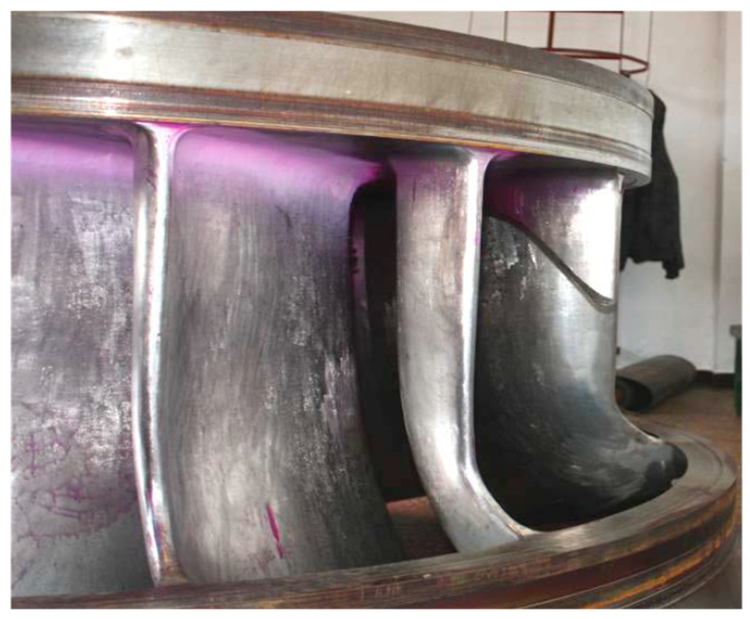
The Francis turbine is one type of widely used hydraulic turbines. Due to the use of higher heads [1], more frequent extreme off-design operations, and a reduced ratio of thickness/weight in runners, as well as occasional small material flaws, many cases of Francis turbine failure have been reported in the literature [2,3,4,5]. Cracking is one of the most common types of damage in Francis turbines. Due to the high stresses, most cracking failures reported in the literature occur on the blades [2,6,7]. A large crack is usually originated from a very small crack or flaw, which is usually undetectable by the current monitoring system, and it will continuously grow under hydraulic dynamic force. If this crack is not detected in time, a catastrophic failure to the machine may occur [2,8]. Figure 1 is a Francis turbine blade failure case reported by [7], in which a large crack occurred on one blade to cause it to nearly break off before being detected. This failure case also indicates the challenge of crack monitoring in Francis turbines. To better monitor this type of crack, it is imperative to research the dynamic behavior of the runner with a crack.
The dynamic behavior of Francis turbines has been widely researched in the literature [9,10]. However, most of these studies were conducted on the intact runners, and the studies on the runners with a crack are very few. In fact, Francis turbines can be seen as one type of bladed-disk structure (or one-dimensionally cyclic system [11,12]). Though it seems the geometries of the band and crown are very different from the disk of the traditional bladed-disk structures, from the theoretical viewpoint, this simplification can be assumed. For bladed-disk structures with a crack, the well-known vibration localization can occur, which has been used for crack monitoring in many other types of turbines [13,14,15,16]. The vibration localization in Francis turbine has been studied very limitedly in the literature. Shuai Wang [17] researched the effect of a crack on the dynamic behavior of a pump-turbine like centrifugal impeller from the viewpoint of the vibration localization in bladed-disk structures. However, the information still is limited.
Generally, for traditional bladed-disk structures, the crack has a more significant influence on blade-dominated modes due to the lower coupling stiffness and causes some modes to be quickly localized to the damaged blade. This is the reason why most of the studies are focused on blade-dominated modes [13,14,15,16]. For the strongly localized mode, the frequency quickly deviates from the original tuned frequency. Therefore, these natural frequency deviations and forced response changes of the runner may be detected by the monitoring system, which is the mechanical basis used for crack monitoring [13,14,15,16].
However, for Francis turbines, the modes at the working frequency area can be disk-dominated (band or crown), particular for the pump turbine [18]. For the turbine researched now (see Figure 2), the modes at the working frequency area usually have high deformations both on the blades and band [9,10]. In some papers, they are called global modes [19], and it is even difficult to distinguish whether they are band-dominated or blade-dominated. Unlike the discrete blades, the band is a continuous structure. Sometimes, to do theoretical research on vibration localization with consideration of the effect of the disk, some researchers also discretized the continuous disk and simplified both the disk sectors and blades into lump masses [12]. This procedure demonstrated that the disk-dominated modes and blade-dominated modes are similar with only some parameter differences (see the Figure 11 in [8]). Therefore, vibration localization can also occur for disk-dominated modes. Even so, it is easy for the disk-dominated modes or blade-dominated modes with high deformations on the disk to have high coupling stiffness between neighboring sectors and it is difficult for strong localization to occur, just as with those shown in [17]. However, this may still depend on the geometry, and unlike the centrifugal impeller, the band of the turbine shown in Figure 2 is more like a thin ring, and the crown usually has low deformation. The parameters of the blades are also different. Moreover, the surrounding water may have large influences. Large uncertainties exist as to whether strong vibration localization can occur in Francis turbines due to cracks and how a crack affects its modes. If strong vibration localization occurs, what is of concern is whether it can cause the natural frequencies to decrease drastically so that it could be detected by the monitoring system. Another item of interest is, under excitation forces, whether the crack can cause a vibration surge to the runner which may also be captured by the monitoring system.
In this paper, the dynamic behavior of a Francis turbine runner model (Figure 2) with a crack will be investigated numerically both in air and in water. The numerical model geometry was used as in [10]. Based on the validation of the intact runner model, a crack was created on one blade. Modal localization theories will be used to explain the modal behavior changes due to the crack. The forced response will be done to check the effect of the crack on response changes. Finally, based on the above analysis, the crack monitoring challenge for the Francis turbine will be analyzed, and the potential technologies to monitor the crack will also be introduced.
2. Theoretical Mode and Theories
2.1. Theoretical Mode
Theoretical modes are commonly used to get general conclusions for one type of bladed-disk structure. In fact, it is sometimes hard to use one simplified theoretical mode to describe the whole vibration behavior of one bladed-disk structure. Taking the widely used lumped parameter model for example, it is usually hard to describe the unbalance problem due to the movements of real turbine blades. For the 1ND (Nodal Diameter [9]) mode of the real turbine, due to the opposite vibration direction of two sides blades, the whole bladed-disk structure usually has a swing movement motion. This additional swing movement may increase the instability of the vibration. When there is a crack on the blade, the instability may have large effects on the vibration. Of course, for different ND modes, this additional movement would be different, and its effect would also be different. This is also true for the Francis turbine with its complicated geometry. However, here, we still try to simplify the Francis turbine runner to make the problem easier to understand.
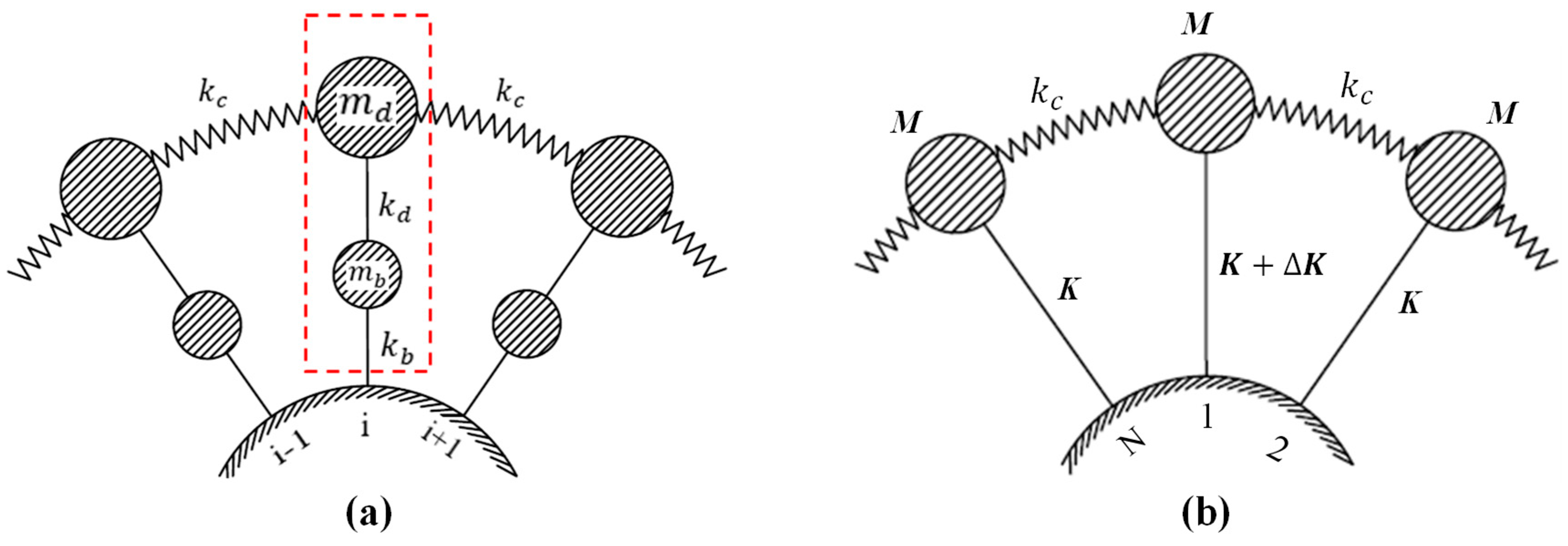
In air, each sector of the Francis turbine consists of one piece of crown, one blade, and one piece of the band. If simplifying each of them to a lump mass using the method in [12], the system will be multi-coupled, which is very complicated. Few theories about the effect of a crack on this system are available in the literature. For the low-order modes of the researched Francis turbine, the crown usually has relatively small modal displacement [10]. If neglecting the crown and seeing the connecting side of blades with it as fixed, the turbine can be simplified to the mode shown in Figure 3a. A similar simplifying method on how to deal with the crown can also be seen in [20]. and are the blade (modal) mass and (modal) stiffness, respectively. The mass simulates the effective mass of the corresponding section of the disk (band), and the stiffness represents the stiffness of the rotor disk(band), whereas the massless spring stiffness provides disk coupling between neighboring sectors. This is a mono-coupled system, and its transfer matrix can be obtained using the method in [12]. However, the matrix is still complicated because of too many parameters.
As mentioned before, this method indicates that the blades and band have similar modal behavior with only some parameter differences. A simpler way is to simplify the band and single blade into one lump mass together as shown in Figure 3b and each lump mass contains two degrees of freedom, namely the band and blade. Therefore, it will have blade-dominated modes and band-dominated modes. The modal behavior of this system with and without a crack has been obtained in [21,22], respectively, which can be seen in Section 2.2.
2.2. Crack Induced Modal Localization in Mono-Coupled System
The whole system has N substructures and each substructure is simplified to a lump mass. Substructures with M mass and K stiffness are mono-coupled with massless springs, whose stiffness is k. Substructure-1 is assumed to have a stiffness change.
For the tuned system, . The modal shapes can be divided into two categories:
where . The corresponding eigenvalues are
where is the coupling effect and is the natural frequency of the undamaged single substructure. The lower and upper limits of passband is
Note that except for equals 1 or N/2 + 1, doublet eigenvalues occur, the corresponding eigenvectors being and (in fact, any linear combination of and is also an eigenvector). For periodic structures, they are usually called ND (node diameter) mode. For N odd, N/2 + 1 is replaced by (N + l)/2 in Equations (1) and (2), and there is only one simple eigenvalue for r = 1.
When substructure-1 has a stiffness change, because of zero substructure-1 deformation of , these modes will not be affected by the mass or stiffness change. All the rest modes will change and become chaos. Unlike the frequencies of other modes changing slightly, the 0ND will quickly drop out of the pass-band and will be the only localized mode to the damaged sub-structure. For the localized mode, the damaged substructure(substructure-1) will have the largest deformation and the deformation on other substructures will symmetrically attenuate around substructure-1. The attenuation rate will be
where the is the stiffness loss ratio of the damaged blade. Obviously, the attenuation rate is an odd function of ratio, the higher , the higher severity of modal localization. The frequency reduction ratio of the localized mode is
This procedure indicates that disk(band)-dominated modes also has modal localization to the disk part if the corresponding blade has damage. However, for the real runner, the instability and complicated blade–disk interaction [23] due to the aforementioned unbalance problem may bring many differences.
3. Simulation Setup
The shape of a turbine runner depends on the design requirements of net head H in m, flow rate Q in , and rotating speed in rad/s. From dimensional analysis techniques all these characteristics are included in the specific speed defined by
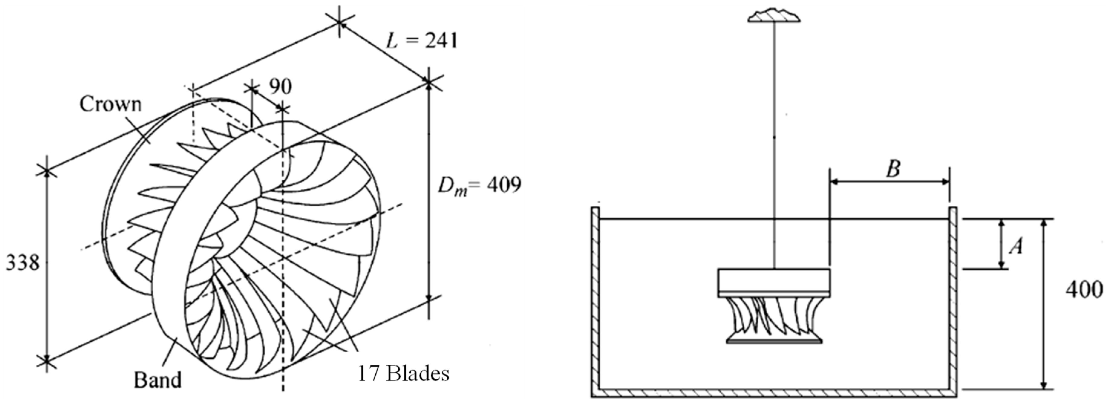
where E is the specific energy given by . The intact runner mode used in this paper is a replica at a reduced scale of 1:10 of a Francis turbine runner with a specific speed of 0.56 [9]. The model runner has 17 blades and a diameter of 409 mm. The shape of the runner with the main dimensions is shown in Figure 2. The material used is a bronze alloy whose properties are given by Table 1.
First, the intact runner model will be validated by comparing its modal analysis results in air and water with the experimental results in [9]. Ansys 16.2 was used to handle all the simulations in this paper, and the acoustic FSI technology is used to simulate the added mass effect from surrounding still water [10,24]. In air, the added mass is very little due to the low density of air compared with the density of the structure and was neglected in this paper. The material property of the acoustic body can be seen in Table 2. When the runner is submerged in water, common nodes technology is used at all the FSI interfaces, and the Asymmetric solver is used in the simulation. In the experiment done in [9], the runner was hung by a low natural frequency rope, which means the runner can be seen as without support. When submerged in water, the distances A and B shown in Figure 1 are 100 mm and 45 mm, respectively. At this distance, the added mass effect is affected little by the distance changes to the surfaces of water domain [9]. The upper surface of the water domain was set as a zero-pressure surface (referring to the atmospheric pressure) and all other outside boundaries of water domain were set as rigid walls. The mesh sensitivity is strictly checked, and when the runner is submerged in water, 192,391 tetrahedral elements are used. Because the damping has little effects on the natural frequencies and modal shapes of the structure, the structure damping and the viscosity of the acoustic body are neglected to save calculating time [9,10]. The comparison between the numerical and experimental results in [9] can be seen in Table 3. As seen, a good agreement has been obtained.
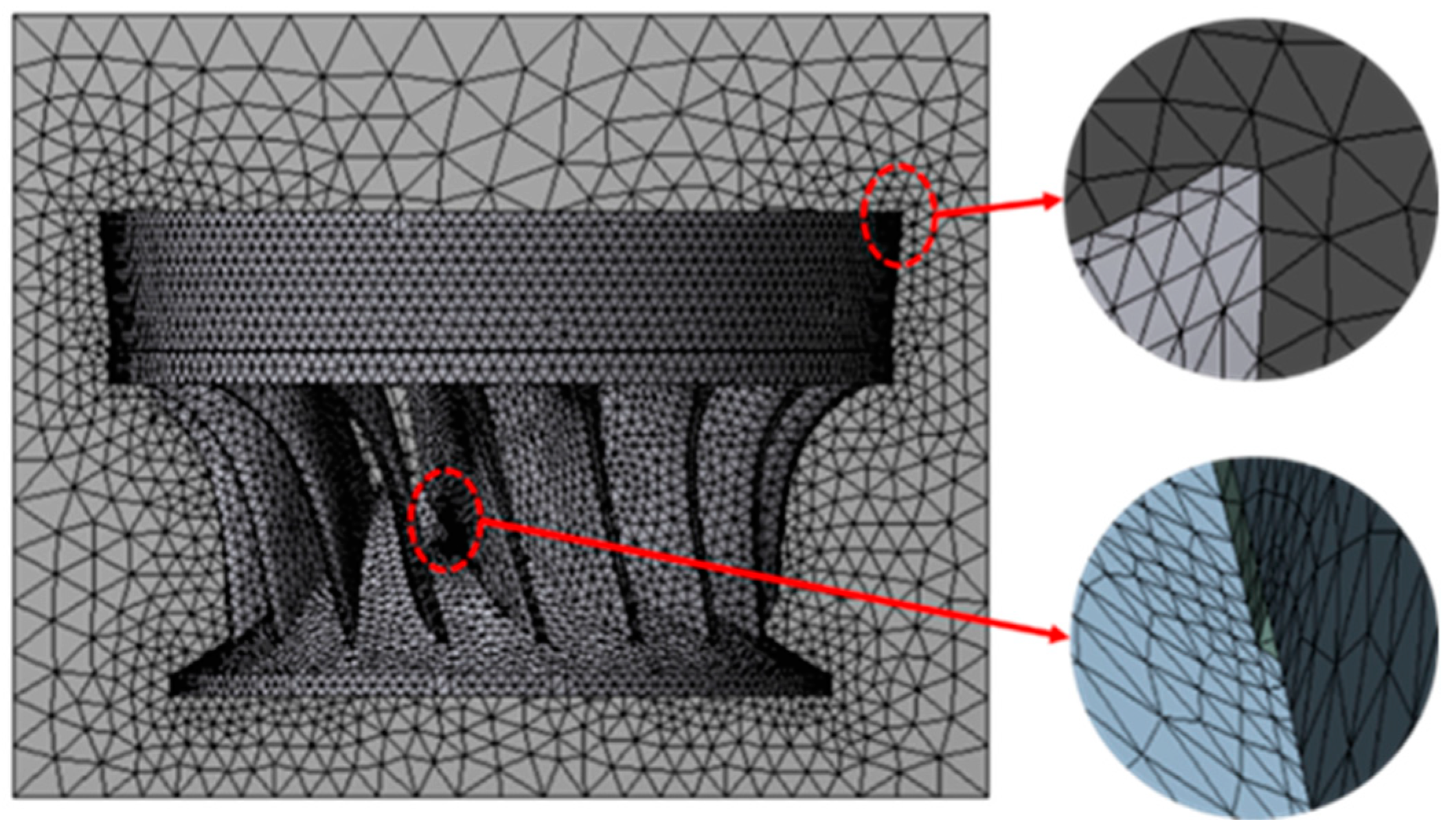
Based on the validation of the intact runner model, a crack is created at the intersection line between one blade and the crown from inside to outside, a location that has been shown to be prone to the appearance of cracks in Francis turbines [7]. The crack is represented as a narrow gap, and this is a linear method that has been used in the literature before [20,22]. The total length of the intersection line is approximately 120 mm, and the crack length in this paper will vary from 0 mm to 100 mm. The mesh density at the crack tip has been especially increased as shown in Figure 4. When submerged in water, the water at the crack clearance is neglected. The effects of the crack on the dynamic behavior of the runner will be investigated. Without the special declaration, the fluid domain and supports will keep the same with those in the validation progress and when these change, it will be declared in each specific section.
4. Results and Discussion
4.1. Modal Behavior
4.1.1. Natural Frequencies and Modal Shapes
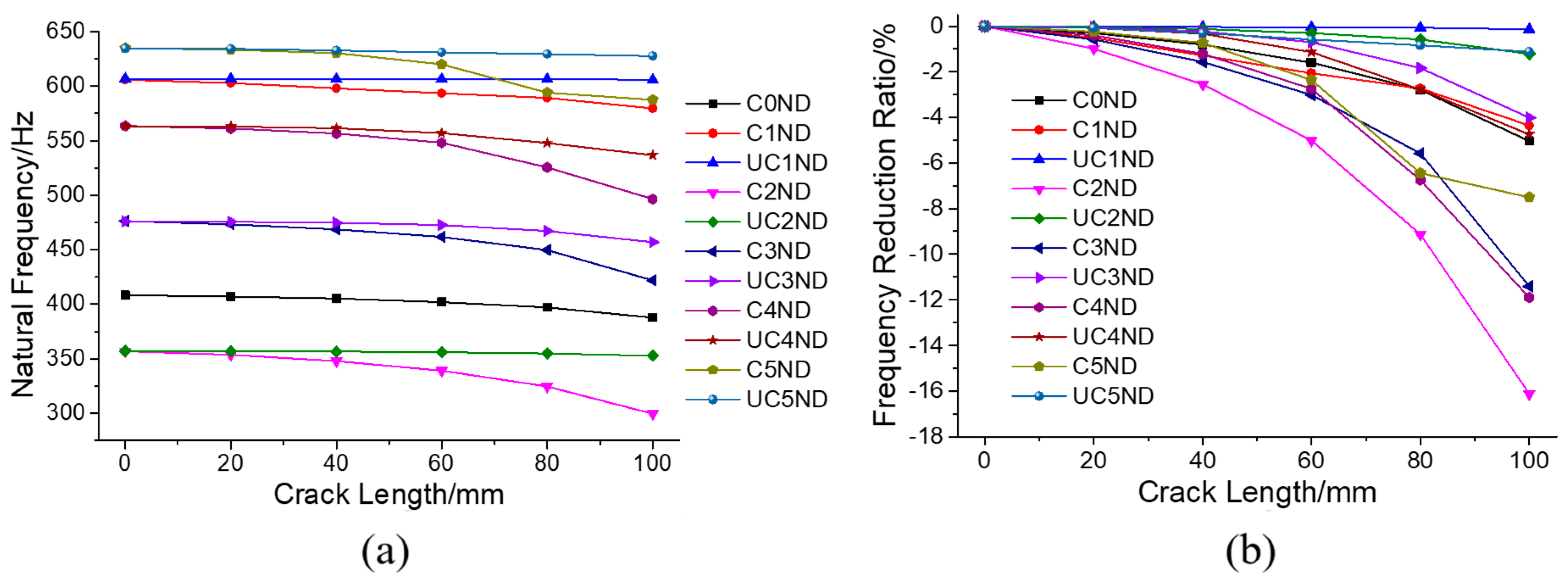
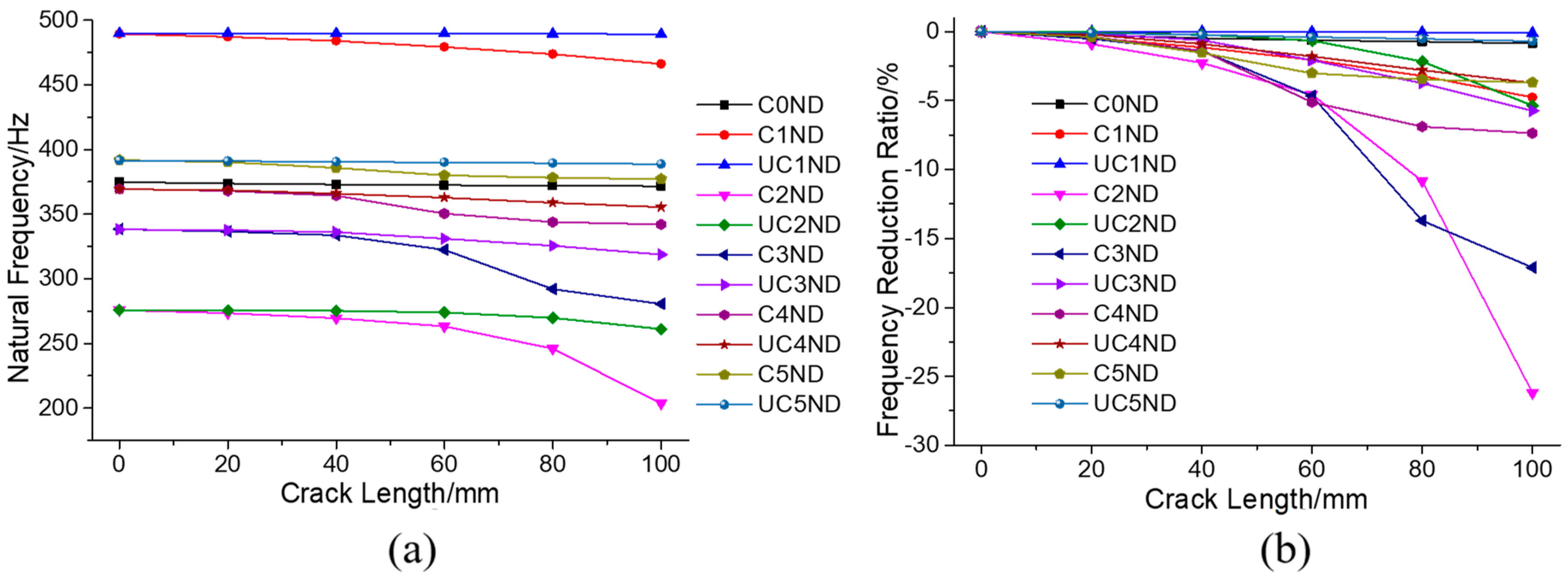
The modal shapes without a crack, with a 60 mm crack, and with a 100 mm crack in the air and water can be seen in Table 4 and Table 5, respectively. For each simulation case, the modal displacement is divided into nine levels from high to low so that they can be compared together. The changes in both the natural frequency and the frequency-reduction ratios with the crack length in air and water can be seen in Figure 5 and Figure 6, respectively.
Obviously, the modal shapes are different in air and in water for the same ND modes with the same crack length, which has also been shown in [10]. This may be mainly because the blades and the band suffer from different added mass factors [9] in water for such structures with the different parts separated enough to have their own dominant modes. Due to the modal shape change from air to water, the frequency changes when increasing the crack length in air and water will also be very different, as shown in Figure 5 and Figure 6. Therefore, the Francis turbine in water can be seen as a new bladed-disk structure with the band, crown, and blades having different densities. Of course, due to the close distance between the blades, each may affect the vibration of nearby blades through hydraulic forces [25], which may cause the system to be multi-coupled [12]. However, for the researched modes, this coupling stiffness from hydraulic force ought to be very small compared with the coupling stiffness from band deformation, and thus its effect may be very limited. Therefore, the effect of a crack on the modal behavior in air and water ought to show many similarities, which can be seen in the following analysis.
From the modal shapes and natural frequencies, one of the doublet modes of each ND will change more than the other one. Generally, for actual turbines, there are no substructures that are without any deformations. Therefore, there are no modes that are completely unaffected by the crack. However, one of the doublet modes of each ND continues to change relatively more and the other one changes much less, which means the principle of the change in modes due to the crack is still in accordance with the theoretical analysis. In the following parts, the modes changing relatively more are referred to as changed modes (C-Mode), and modes changing relatively less are referred to as unchanged modes (UC-Mode).
When comparing the modal shape changes of the changed and unchanged doublet modes of each ND with the change in crack length, for most ND modes the changed mode usually originates from the one with low deformation on the damaged blade, and the damaged blade is close to the zero-displacement node. In contrast, for the 1ND and 8ND modes, which have nearly zero deformation blades, the changed mode usually originates from the one with high deformation on the damaged blade, and the damaged blade is far from the zero-displacement node.
The modal shape changes with the increase in crack length are not that regular, which may be because of the vibration instability mentioned above under the complicated high-intensity interaction. Due to the differences in vibration motion of the different ND modes, the changes can vary significantly. For all the unchanged modes, the modal shapes may also become distorted to some extent with the increase in crack length. Apart from the unchanged 1ND, which has low deformation at the damaged blade, the damaged blade is prone to have a large deformation close to the beginning part of the crack. This high deformation can cause the energy to concentrate at that part, which will induce a deformation degeneration at the band and other blades.
For the changed modes, the modal shape changes are even more irregular than those of the unchanged modes. Sometimes, under certain crack lengths, the highest deformation may appear at blades near the damaged blade, but when the crack length is very large, it will finally transmit to the damaged blade, like the changed 2ND and 3ND mode in air. Obviously, both in the air and in water, the changed 2ND mode has a high deformation concentration in the band near the damaged blade. This is the only mode that has a deformation concentration on the band near the damaged blade. Therefore, it ought to be the localized mode. The concentration usually is at the band piece next to the damaged blade sector when the crack is short, but it will finally transmit to the damaged blade sector, and the localization becomes very strong when the crack is large.
The 3ND in the air with a crack length of 100 mm is a special case, which has a high deformation concentration on the damaged blade with a strong deformation degeneration at the band and other blades. This mode may not be the localized mode because the band deformation has no concentration near the damaged blade. The origin of this mode may be the vibration instability mentioned earlier. The 3ND mode in water presents an interesting situation. When the crack is not too long, for example, 60 mm, this mode shows a high deformation concentration on the damaged blade with deformation degeneration on the band. However, when the crack is long, for example, 100 mm, the modal shape of the changed 3ND becomes similar to that of the 2ND. From Figure 6, the natural frequency of the changed 3ND with a 100 mm crack is close to that of the 2ND mode. This means that when the changed modes are close to other modes with the reduction of frequencies, the modal shapes will become similar to the nearby one.
For the unchanged modes, the frequency reduction ratios are usually lower than 5% when the crack length is 100 mm. For some modes, such as the unchanged 1ND, the frequency reduction ratio can be as low as 0.1%. For the changed modes, the localized mode usually has a relatively high-frequency reduction ratio. When the crack length is 100 mm, the frequency reduction ratios of the localized 2ND can be as high as 16% in air and 26.5% in water. Though the changed 3ND mode in air has a high deformation concentration on the damaged blade when the crack length is 100 mm, its frequency reduction ratio is much lower than the localized 2ND. This may have a relationship with the damaged blade deformation, which means that for the changed 3ND mode, the deformation concentrates on the beginning part of the crack in the damaged blade and this modal shape of the damaged blade may not cause a high stiffness reduction ratio. However, when in water with a crack length of 60 mm, the frequency reduction ratio of the 3ND mode is higher than that of the localized 2ND mode. In addition to the damaged blade having a modal shape with the highest deformation at its middle part, the deformation concentration degree may also contribute to it, which means the changed 3ND has a higher deformation concentration degree than the localized 2ND mode in water with a crack of 60 mm.
As mentioned earlier, when the changed modes are close to other modes with the reduction of frequencies, the modal shapes will become similar to those modes. This phenomenon may have large effects on the frequency reduction ratios of the changed modes. In water, this phenomenon can be more significant than in air because the frequencies of different modes are closer. For the changed 3ND, 4ND, and 5ND modes in water, as well as the changed 5ND mode in air, when this phenomenon occurs with an increase in crack length, the frequency reduction rate is greatly decreased. Overall, the natural frequency changes for all ND modes are small when the crack is not long enough. This is due to two main reasons. On the one hand, though the band is like a thin ring, the couplings between neighboring sectors are still very high. On the other hand, the blades are firmly constrained by the band and the crown, which may reduce the stiffness reduction ratio. For different modes, the frequency reduction ratios can vary significantly.
In reality, the runner is connected to the shaft. By assuming that the shaft is nearly rigid, a fixed support is given to the top face of the crown, as shown in Figure 7 (support A and this support is the same with that used in the harmonic response later), and the modal shapes under the fixed support in the air are shown in Table 6. Due to the fixed support, the 0ND, 1ND, and 2ND modes were reduced from 408.38 Hz, 605.84 Hz, and 356.95 Hz to 256.43 Hz, 301.43 Hz, and 369.27 Hz, respectively. The modal shapes of 0ND and 1ND also change a lot. This means that these modes have relatively high deformations on the crown. The fixed support at the top face can be more or less seen as increasing the stiffness of the crown, which will greatly change the blade–disk (band) interaction properties of these modes. The natural frequencies of the higher ND modes are nearly unaffected by the fixed support. Obviously, the 0ND mode quickly becomes localized with the increase in crack length. The interesting thing about the 1ND is that it also shows some localization, even though the degree of localization is much less than 0ND. The 2ND mode no longer has localization. The 3ND mode still shows a strong deformation concentration at the damaged blade when the crack is 100 mm. From the above analysis, the mode with the lowest natural frequency is most prone to localize. This may have a relationship with the blade–disk interaction property and the mode with the lowest frequency is just at its veering point [23]. That 1ND shows some localization may be because of its relatively low frequency and the strong instability of its vibration. When there is no fixed support at the crown, the 1ND mode is at a high-frequency area, and no localization occurs on it. Considering the low degree of localization of 1ND, it may be considered that there is still only one localized mode.
4.1.2. FFT of Modal Shapes and the Localization Factor
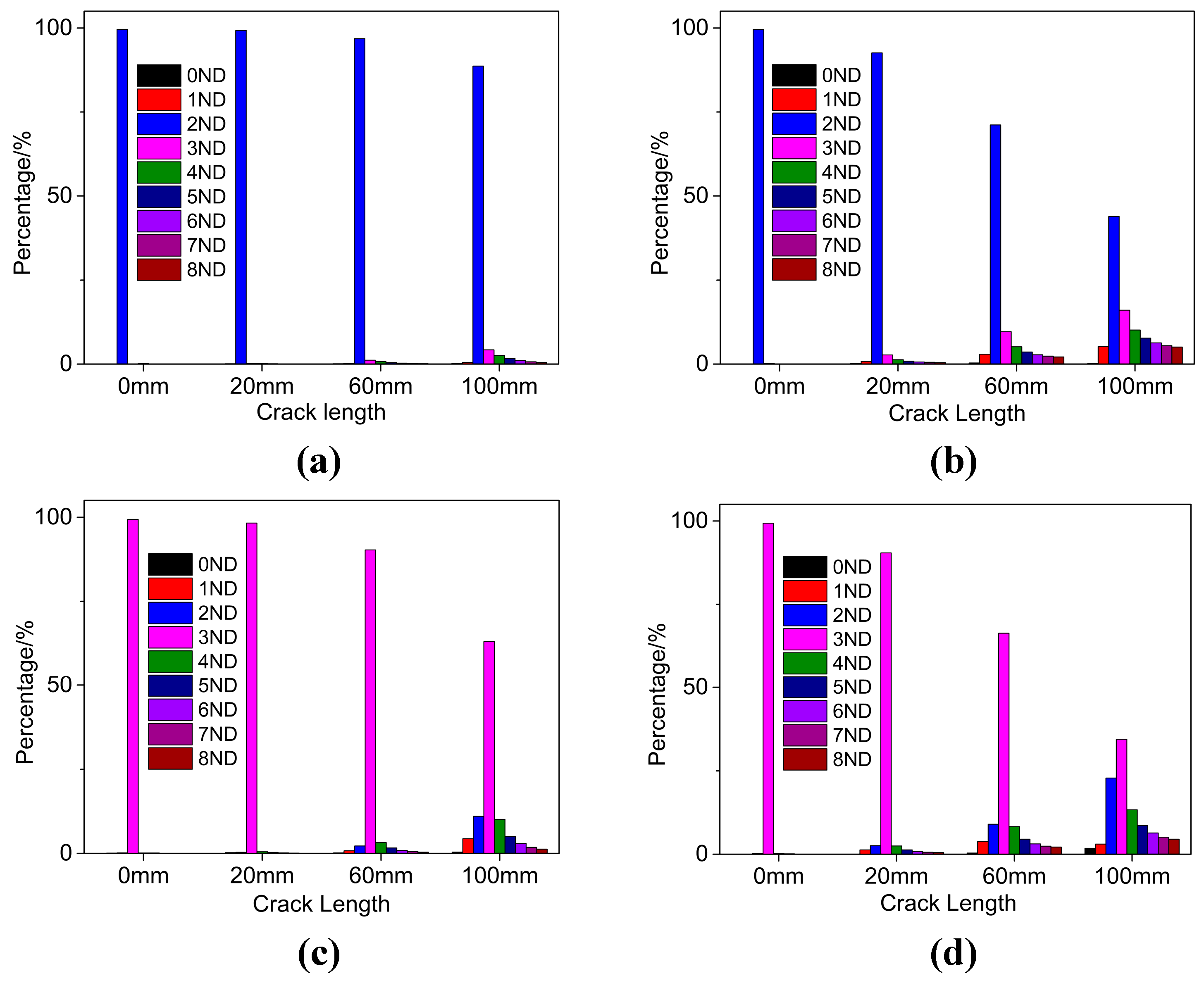
The modal shape change due to a crack can also be described using a Fast Fourier Transform (FFT) of the modal shape. The first step of this procedure is to choose the sample point to represent the modal shape change. First, the sample point is chosen as the intersection point of the trailing edge and the band for each blade. Therefore, 17 sample points were obtained, and the modal displacement variation of these 17 points for each mode was used for FFT. The FFT results of the changed 2ND, unchanged 2ND, unchanged 3ND, and changed 3ND in air for crack lengths of 0 mm, 20mm, 60 mm, and 100 mm are shown in Figure 8a–d, respectively. Each modal shape can be seen to be synthesized by different ND harmonic waveforms with different magnitudes. For each ND, its value was plotted by the percentage of its magnitude to the sum of the magnitudes of all ND waveforms.
Without a crack, each modal shape clearly contains only one waveform. With the increase in crack length, the percentage value of this original waveform will continue to decrease and other ND waveforms will appear with an increasing percentage value. For the unchanged modes, the decrease in the original ND waveform and the increase other ND waveforms are very insignificant, while for the changed modes, they are much more significant, particularly for the localized mode and the mode with a strong deformation concentration on the damaged blade (like the changed 3ND in Figure 8d). The values of the new appearing ND waveforms usually decrease with their separation from the original ND waveform.
For a Francis turbine, the excitation from the hydraulic force is due to the rotor–stator interaction and the excitation is order excitation [26]. To make the runner resonant, both the frequency and the ND of the excitation should be in accordance with the runner mode. This is to say that only the mode with the same ND can extract energy from the excitation force. When a crack is present, other ND waveforms start to appear. This means that the mode now can not only be excited by the original ND excitation but also be excited by other ND excitations. With an increase in the crack length, the decrease in the original ND percentage value means the ability to extract energy from the corresponding ND excitation decreases and the increase in the other ND percentage values means the ability to extract energy from the corresponding ND excitation increases [27]. However, the FFT value change may depend on the sample points positions because with the crack, the deformations on the blades, particular the damaged blade, become very ununiform. With other groups of sample points, the FFT results may vary a lot and become not that regular. Using those sample points may be not appropriate because of the locally unregular deformation change on the damaged blade, and it may be better to use the sample points on the band.
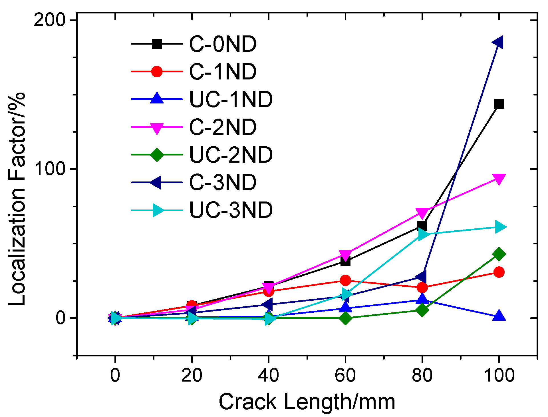
The maximum response under order excitation not only depends on the FFT value change but also depends on the Localization Factor (LF) [28] change. The LF is defined as
where is the maximum modal displacement of one mode without a crack and is the maximum modal displacement of the mode with a crack. The LF describes the frequency response function (FRF) [29] change due to the crack under point excitation for one mode. Of course, the damping is not considered in the modal analysis, and this may have some effects on the LF values. With damage, the deformation will have concentrations, which will induce the increase of the modal displacement. When the frequency change due to a crack is not that too large, the deformation concentration will increase the LF value. From Figure 9, for most of the modes, the LF will increase with the crack length increase. The increases for changed modes are much more significant than the unchanged modes due to higher deformation concentrations. The localized mode and modes with high deformation concentrations on the damaged blade are prone to have high LF value increases.
4.2. Forced Response
The forced response was carried out through harmonic response analysis. The top face of the crown was fixed, and the amplitude of dynamic pressure was 0.01 MPa (seen in Figure 7). Here we use the constant pressure amplitude to study the property change of the runner, which is a common method used in [14,16,17,22]. In ref. [22], the analytic method was used to analyze the forced response of the localized 0ND in a mono-coupled lumped parameter system. However, the forced responses of other nonlocalized modes were not studied. Furthermore, the analytical method is very complicated and not very intuitive. For a real Francis turbine, the response may also be not as regular as those in a lumped parameter system. In this paper, the forced response will be analyzed based on the modal shape FFT results and LF value changes, which are more intuitive and easier to understand. Dynamic pressures were applied to the pressure side of each blade. To get certain ND order excitation, there were corresponding phase changes between neighboring blades. Because in water, the modal behavior changes are similar with those in air, the forced response was only done for the runner in air.
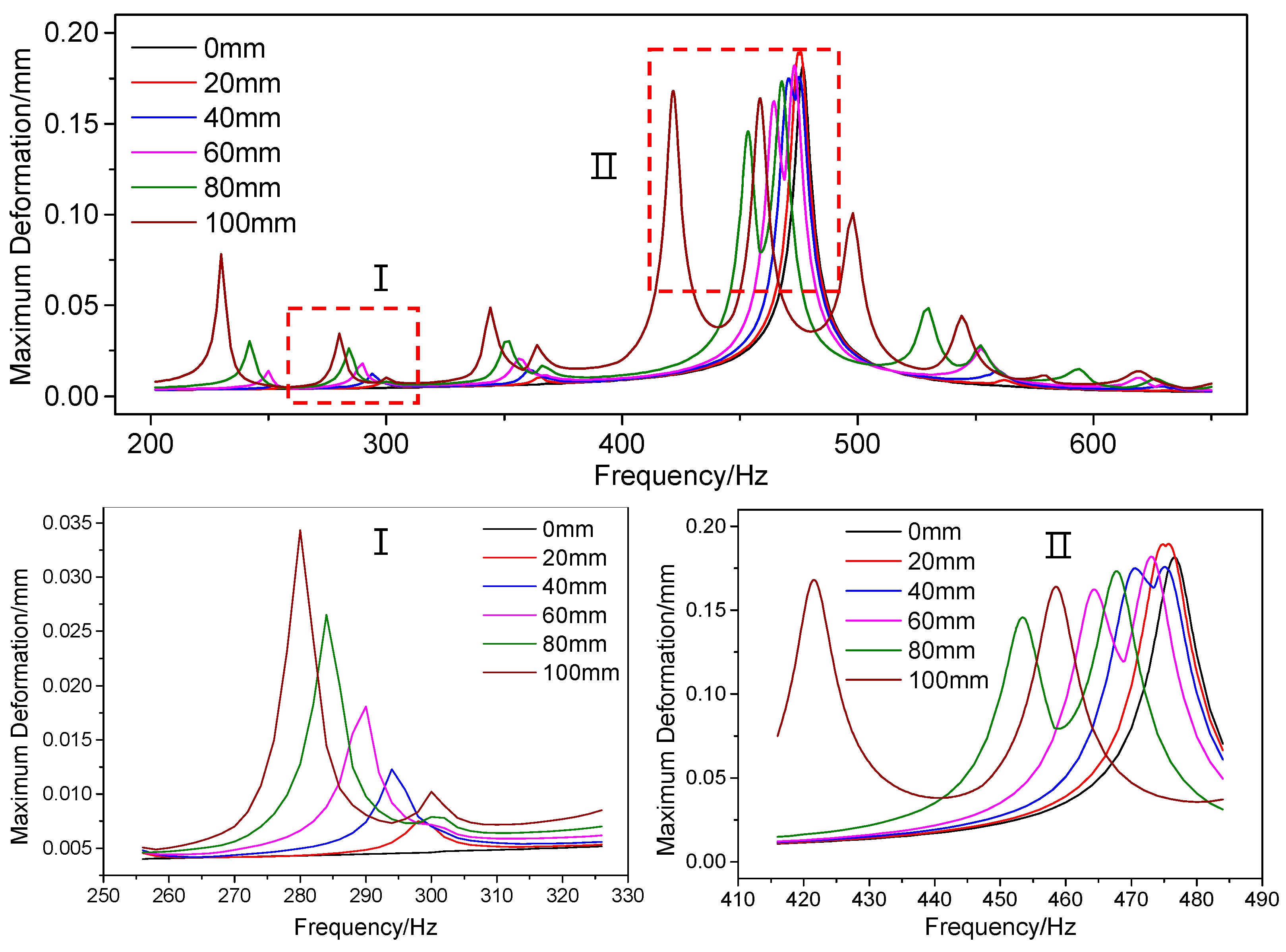
The forced responses under 3ND excitation are shown in Figure 10. The experimental damping ratio of 3ND mode 0.0068 in [9] was implemented. The FFT and LF values obtained above are based on the modal analysis without fixed support on the crown. However, for 3ND mode, the effects of fixed support are very small, and the LF values will also be affected little. The FFT and LF changing laws will also stay the same as those without support. Therefore, they are still used to explain the forced response changes.
For 3ND excitation, the unchanged and changed 3ND modes certainly have the highest responses (shown in Ⅱ of Figure 10). For the undamaged runner, there is only one peak due to the same natural frequencies of the changed and unchanged 3ND modes. With the increase in crack length, these two modes become separated, and two peaks appear. The first peak corresponds to the changed mode and the second peak corresponds to the unchanged mode. For the changed 3ND mode, the response with a crack of 20 mm is the highest, which means the increase of the LF value is faster than the decrease of 3ND FFT percentage value from 0 mm to 20 mm. From 20 mm to 80 mm, the response decreases gradually, which is because the 3ND FFT value of this mode decreases fast, while the LF value increases moderately during the progress. From 80 mm to 100 mm, there is a drastic response increase, which is due to the drastic LF value increase as shown in Figure 9. For the unchanged 3ND mode, the response with a 20 mm long crack is also highest. When with a 20 mm crack, the peaks of changed and unchanged modes are very close, and they may affect each other’s response to some extent. From 20 mm to 100 mm, the response change is not that regular and reaches its minimum at 100 mm. From Figure 9, the LF value of the unchanged 3ND mode increases drastically from 20 mm to 80 mm, which may be the reason why the response at 60 mm is higher than that at 40 mm. At 40 mm, the peaks of changed and unchanged modes are approximately the same, which is because the LF value of the changed mode is a little higher while the FFT value a little lower than those the unchanged mode. At 60 mm or 80 mm, the peak of the unchanged mode is much higher than that of the changed mode due to both higher LF and FFT values. At 100 mm, the levels of these two peaks are close again.
For the 1ND mode without a crack under 3ND excitation, the response (seen in Ⅰ of Figure 10) certainly is very low. With the increase in crack length, the response of the changed 1ND mode increases drastically. This is because both the 3ND FFT value and the LF value of 1ND mode increase with the crack length. The response of unchanged 1ND under 3ND excitation is much lower, and only a little peak appears when the crack is 100 mm. The response changes of 0ND, 2ND, and 4ND modes are similar to that of 1ND. However, the responses of 0ND and 4ND with a crack of 100 mm are much higher than that of 2ND. This is because of the great increases of the LF values due to the high deformation concentrations of these two modes (see Figure 9). When the crack length is not that high, such as less than 60 mm, all these peak levels are limited due to the moderate increases of the LF and FFT values.
Overall, both for the changed and unchanged modes under the same ND excitation, with the increase in crack length, the responses usually increase first and then decrease, even though the increase and decrease progresses are not monotone. This change progress is similar to the forced response changes of the localized mode in the lumped parameter system [22]. Except for the localized 0ND, the forced responses of other modes decrease with separating from 3ND. This is because the FFT percentage values of new appearing ND waveforms for each mode usually decrease with their separation from the original ND waveform as aforementioned. This also means that for both the localized and nonlocalized modes, the response will decrease with the excitation order separating from the original ND of the mode. Therefore, the forced responses of localized and nonlocalized modes indeed share many similarities. From the response peak changes of all the modes, the method that uses the FFT and LF value changes to explain the response changes is basically appropriate.
4.3. Crack Monitoring Challenges
For the researched Francis turbine mode, when the crack length is high, the frequency reduction ratios can be higher than 20% (mainly referring to the localized mode or the modes with strong deformation concentrations on the damaged blade). However, when the crack is not that large, the natural frequency reduction ratios are usually less than 10%. Even for a real Francis turbine runner with more complicated fluid domain and supports, it is still difficult for the maximum frequency reduction ratio to be high due to the high coupling stiffness. For this type of machine, there is usually a safety margin in daily operations to avoid resonance, such as 20% of the natural frequency (corresponding to the ND of the RSI excitation). Therefore, it is very difficult for the natural frequency to fall to the operating area to be excited and to be detected by the current monitoring system.
Though the responses of other modes (not corresponding to the ND of the RSI excitation) increase with crack length and these modes are in the operating region, when the crack length is not high enough (often less than 60 mm), the response increases are still limited. Therefore, they might very easily be confused with a load change, and it can be difficult to activate the vibration alarm of the turbine. Another very important thing is that the current monitoring system is usually at the bearing of the turbine. The vibration of the runner must be transmitted to the bearing through the shaft, and the vibrations are also easily confused with the bearing effect. The response used in this paper is the maximum response of the runner, which is also used in many other papers [14,16,17]. However, due to the vibration transmitting to the monitoring system, the equivalence between the maximum local response increases due to a crack and the vibration increase captured by the monitoring system is still doubtful.
For the Francis turbine shown in Figure 1, its modal behavior is still not that clear, and the crown may have a high deformation. Under this situation, it will be multi-coupled, and more than one localized mode may appear. Doublet modes can still be divided into changed modes and unchanged modes, just as for the impeller in [17]. However, the higher deformation at the crown will greatly increase the coupling stiffness, which will cause the natural frequency reduction ratios and the response changes to be much lower Equations (5) and (6) [22]. This will greatly increase the monitoring difficulty and may be the reason why such a large crack was not detected by the monitoring system.
The value of the current research is twofold. First, it clarifies the effect of a crack on the dynamic behavior of a Francis turbine from the viewpoint of vibration localization and the challenge of crack monitoring. Second, this research can provide some references for more advanced crack-monitoring technologies. Though the frequency deviations are low, they probably can be captured by more advanced monitoring technologies. David Valentín et al. [19] have done some research on the feasibility of detecting natural frequencies of hydraulic turbines while in operation using strain gauges. Therefore, the natural frequency changes of the runner in operation perhaps can be detected more accurately and, through these changes, the crack maybe can be detected much earlier. Of course, the phenomenon that the modal shape of the changed mode may become similar to another mode when their frequencies are close as aforementioned should be paid special attention to during the progress, because when the natural frequencies and modal shapes are similar, they are very easily confused, which may greatly increase the monitoring difficulty. It seems that the lowest frequency mode is ideal for monitoring because it is usually the localized mode which has the highest frequency reduction ratio and is not affected by the above-mentioned phenomenon. However, due to the lowest frequency, its frequency value change may also be very low, which makes it easy to be confused by the monitoring errors. While the higher frequency modes have advantages in this aspect, R.A. Saeed et al. [30] has done some works on crack monitoring using artificial intelligence technology based on the maximum forced responses of the runner. However, the maximum response may be difficult to obtain in the real case. Anyway, this technology has developed very fast during the past few years and shows great potential [31]. Due to the low frequency and response changes as shown in the above analysis, this technology combined with the on-runner measurements is especially recommended for further research in the future.
5. Conclusions
The modal behavior and forced responses of a Francis runner model with a crack were studied numerically in this paper, and the crack-induced vibration localization theory was used to explain the dynamic behavior changes. Some main conclusions are as follows:
For the studied Francis runner model, the crown has a low modal displacement. Therefore, it can almost be seen as a mono-coupled system. There is usually only one localized mode, and when the crack length is high, strong localization can occur. The mode with the lowest natural frequency is easiest to localize. The singlet modes and one of the doublet modes for each ND will change much more, and the remaining doublet modes will change much less. All these match the theories well. However, perhaps due to the vibration instability, the modal shape changes are not that regular, and some non-localized modes may show strong deformation concentrations on the damaged blade. The frequency reduction ratios of the changed modes are relatively higher than those of unchanged modes. The localized mode or the modes with strong deformation concentrations on the damaged blade usually have the highest natural frequency reduction ratios. The modal shapes and frequency reduction ratios in water are different from those in the air because the band and blades suffer from different added mass factors in water. The modal shape of a changed mode may become similar with another mode when their frequencies are close. The FFT percentage value of the original ND for one mode usually decreases with the increase in crack length, while the FFT percentage values of other NDs usually increase with the increase in crack length. The LF values usually increase with an increase in crack length and the LF value changes of the changed modes are usually more significant than those of the corresponding ND unchanged modes.
For one mode under the same ND excitation with constant pressure amplitude, the forced response usually first increases and then decreases with the increase in crack length, but the progress may not be monotone. The response of one mode under other ND excitations will increase gradually, and the response can be very high when the crack is large. The method of using the FFT and LF value changes to explain the response changes is basically appropriate.
Though the band is similar to a thin ring, it is still very stable. Therefore, the coupling stiffness is very high, which makes the natural frequency reduction ratios less than 10% and the forced response changes limited when the crack is not large enough. These are the reasons why it is difficult to monitor the crack in this type of runner. The research in this paper can provide some references for more advanced monitoring technologies.
Author Contributions
M.Z. did the simulation and wrote the paper; D.V., C.V. contributed jointly by supervising the overall work and overall structure of the paper; M.E. and W.Z. helped to improve the quality of some pictures and the language of the paper.
Funding
The present research work was financially supported by China Scholarship Council.
Conflicts of Interest
The authors declare no conflict of interest.
Nomenclature
| FFT | Fast Fourier Transform | LF | Localization Factor |
| Blade modal mass | Disk modal mass | ||
| Blade modal stiffness | Disk modal stiffness | ||
| Coupling stiffness | N | Number of blades | |
| M | Mass of the substructure | K | Stiffness of the substructure |
| Stiffness change of the substructure | Cosine category of modal shapes | ||
| Sine category of modal shapes | Attenuation rate | ||
| Stiffness loss ratio | |||
| ND | Nodal Diameter | Coupling stiffness | |
| Lower limit of the pass-band | Upper limit of the pass-band | ||
| H | Net head | Q | Flow rate |
| Rotating Speed | E | Specific energy | |
| g | Gravitational acceleration | Specific speed | |
| Modal displacement of the substructure | |||
| Phase change of neighboring substructures | |||
| Natural frequency of the undamaged substructure | |||
| Frequency reduction ratio of the localized mode | |||
| maximum modal displacement of one mode without crack | |||
| maximum modal displacement of one mode with crack | |||
References
- Valero, C.; Egusquiza, M.; Egusquiza, E.; Presas, A.; Valentin, D.; Bossio, M. Extension of Operating Range in Pump-Turbines. Influence of Head and Load. Energies 2017, 10, 2178. [Google Scholar] [CrossRef]
- Liu, X.; Luo, Y.; Wang, Z. A review on fatigue damage mechanism in hydro turbines. Renew. Sustain. Energy Rev. 2016, 54, 1–14. [Google Scholar] [CrossRef]
- Egusquiza, E.; Valero, C.; Estévez, A.; Guardo, A.; Coussirat, M. Failures due to ingested bodies in hydraulic turbines. Eng. Fail. Anal. 2011, 18, 464–473. [Google Scholar] [CrossRef]
- Egusquiza, E.; Valero, C.; Huang, X.; Jou, E.; Guardo, A.; Rodriguez, C. Failure investigation of a large pump-turbine runner. Eng. Fail. Anal. 2012, 23, 27–34. [Google Scholar] [CrossRef] [Green Version]
- Padhy, M.K.; Saini, R.P. A review on silt erosion in hydro turbines. Renew. Sustain. Energy Rev. 2008, 12, 1974–1987. [Google Scholar] [CrossRef]
- Flores, M.; Urquiza, G.; Rodríguez, J.M. A Fatigue Analysis of a Hydraulic Francis Turbine Runner. World J. Mech. 2012, 2, 28–34. [Google Scholar] [CrossRef]
- Frunzǎverde, D.; Muntean, S.; Mǎrginean, G.; Şerban, V.; Marsavina, L.; Terzi, R. Failure analysis of a Francis turbine runner. IOP Conf. Ser. 2010, 12, 012115. [Google Scholar] [CrossRef] [Green Version]
- Egusquiza, E.; Valero, C.; Valentin, D.; Presas, A.; Rodriguez, C.G. Condition monitoring of pump-turbines. New challenges. Measurement 2015, 67, 151–163. [Google Scholar] [CrossRef] [Green Version]
- Rodriguez, C.G.; Egusquiza, E.; Escaler, X.; Liang, Q.W.; Avellan, F. Experimental investigation of added mass effects on a Francis turbine runner in still water. J. Fluids Struct. 2006, 22, 699–712. [Google Scholar] [CrossRef] [Green Version]
- Liang, Q.W.; Rodríguez, C.G.; Egusquiza, E.; Escaler, X.; Farhat, M.; Avellan, F. Numerical simulation of fluid added mass effect on a Francis turbine runner. Comput. Fluids 2007, 36, 1106–1118. [Google Scholar] [CrossRef]
- Cai, C.W.; Cheung, Y.K.; Chan, H.C. Mode localization phenomena in nearly periodic systems. J. Appl. Mech. 1995, 62, 141–149. [Google Scholar] [CrossRef]
- Ottarsson, G.; Pierre, C. Vibration localization in mono-and bi-coupled bladed disks—A transfer matrix approach. In Proceedings of the 34th Structures, Structural Dynamics and Materials Conference, La Jolla, CA, USA, 19–22 April 1993. [Google Scholar]
- Saito, A.; Castanier, M.P.; Pierre, C. Effects of a cracked blade on mistuned turbine engine rotor vibration. J. Vib. Acoust. 2009, 131, 061006. [Google Scholar] [CrossRef]
- Kuang, J.H.; Huang, B.W. The effect of blade crack on mode localization in rotating bladed disks. J. Sound Vib. 1999, 227, 85–103. [Google Scholar] [CrossRef]
- Jung, C.; Saito, A.; Epureanu, B.I. Detection of cracks in mistuned bladed disks using reduced-order models and vibration data. J. Vib. Acoust. 2012, 134, 061010. [Google Scholar] [CrossRef]
- D’Souza, K.; Saito, A.; Epureanu, B.I. Reduced-Order Modeling for Nonlinear Analysis of Cracked Mistuned Multistage Bladed-Disk Systems. AIAA J. 2012, 50, 304–312. [Google Scholar] [CrossRef]
- Wang, S.; Zi, Y.; Li, B.; Zhang, C.; He, Z. Reduced-order modeling for mistuned centrifugal impellers with crack damages. J. Sound Vib. 2014, 333, 6979–6995. [Google Scholar] [CrossRef]
- Valero, C.; Huang, X.; Egusquiza, E.; Farhat, M.; Avellan, F. Modal behavior of a reduced scale pump turbine impeller. Part II: Numerical simulation. IOP Conf. Ser. 2010, 12, 012117. [Google Scholar] [CrossRef] [Green Version]
- Valentin, D.; Presas, A.; Bossio, M.; Egusquiza, M.; Egusquiza, E.; Valero, C. Feasibility of Detecting Natural Frequencies of Hydraulic Turbines While in Operation, Using Strain Gauges. Sensors 2018, 18, 174. [Google Scholar] [CrossRef] [PubMed]
- Huang, B.-W. Effect of number of blades and distribution of cracks on vibration localization in a cracked pre-twisted blade system. Int. J. Mech. Sci. 2006, 48, 1–10. [Google Scholar] [CrossRef]
- Wei, S.T.; Pierre, C. Localization phenomena in mistuned assemblies with cyclic symmetry part I: Free vibrations. J. Vib. Acoust. Stress Reliabil. Des. 1988, 110, 429–438. [Google Scholar] [CrossRef]
- Fang, X.; Tang, J.; Jordan, E.; Murphy, K.D. Crack induced vibration localization in simplified bladed-disk structures. J. Sound Vib. 2006, 291, 395–418. [Google Scholar] [CrossRef]
- Castanier, M.P.; Pierre, C. Modeling and Analysis of Mistuned Bladed Disk Vibration: Current Status and Emerging Directions. J. Propuls. Power 2006, 22, 384–396. [Google Scholar] [CrossRef]
- ANSYS, CFX. 16.2: User’s Manual; ANSYS Inc.: Canonsburg, PA, USA, 2015. [Google Scholar]
- Valentín, D.; Presas, A.; Egusquiza, E.; Valero, C.; Egusquiza, M. Experimental Study of a Vibrating Disk Submerged in a Fluid-Filled Tank and Confined with a Nonrigid Cover. J. Vib. Acoust. 2017, 139, 021005. [Google Scholar] [CrossRef]
- Rodriguez, C.G.; Egusquiza, E.; Santos, I.F. Frequencies in the vibration induced by the rotor stator interaction in a centrifugal pump turbine. J. Fluids Eng. 2007, 129, 1428–1435. [Google Scholar] [CrossRef]
- Castanier, M.P.; Pierre, C. Using Intentional Mistuning in the Design of Turbomachinery Rotors. AIAA J. 2002, 40, 2077–2086. [Google Scholar] [CrossRef]
- Wang, J.J.; Li, Q.H. Methods and Applications of Reduction Modeling for Mistuned Bladed Disk Vibration in Aero-Engine; National Defense Industry Press: Beijing, China, 2009. [Google Scholar]
- Presas, A.; Valentin, D.; Egusquiza, E.; Valero, C.; Egusquiza, M.; Bossio, M. Accurate Determination of the Frequency Response Function of Submerged and Confined Structures by Using PZT-Patchesdagger. Sensors 2017, 17, 660. [Google Scholar] [CrossRef] [PubMed]
- Saeed, R.A.; Galybin, A.N.; Popov, V. 3D fluid–structure modelling and vibration analysis for fault diagnosis of Francis turbine using multiple ANN and multiple ANFIS. Mech. Syst. Signal Process. 2013, 34, 259–276. [Google Scholar] [CrossRef]
- Liu, R.; Yang, B.; Zio, E.; Chen, X. Artificial intelligence for fault diagnosis of rotating machinery: A review. Mech. Syst. Signal Process. 2018, 108, 33–47. [Google Scholar] [CrossRef]
Figure 1.
Francis turbine blade failure case reported by D Frunzăverde, 2010 [7].
Figure 1.
Francis turbine blade failure case reported by D Frunzăverde, 2010 [7].

Figure 2.
Geometry of the model and the view submerged in water [9].
Figure 2.
Geometry of the model and the view submerged in water [9].

Figure 3.
Theoretical modes (a) Lumped parameter mode with two lumped masses (b) Lumped parameter mode with single lumped mass.
Figure 3.
Theoretical modes (a) Lumped parameter mode with two lumped masses (b) Lumped parameter mode with single lumped mass.

Figure 4.
View of the mesh.

Figure 5.
Natural frequency changes and change ratios in air (a) Natural frequencies (b) Frequency change ratios.
Figure 5.
Natural frequency changes and change ratios in air (a) Natural frequencies (b) Frequency change ratios.

Figure 6.
Natural frequency changes and change ratios in water (a) Natural frequencies (b) Frequency change ratios.
Figure 6.
Natural frequency changes and change ratios in water (a) Natural frequencies (b) Frequency change ratios.

Figure 7.
Supports and loads in harmonic response analysis.

Figure 8.
Fast Fourier Transform (FFT) results of different modal shapes (a) Unchanged 2ND (b) Changed 2ND (c) Unchanged 3ND (d) Changed 3ND.
Figure 8.
Fast Fourier Transform (FFT) results of different modal shapes (a) Unchanged 2ND (b) Changed 2ND (c) Unchanged 3ND (d) Changed 3ND.

Figure 9.
Localization factors (LF) value changes with the crack length.

Figure 10.
Forced responses under 3ND excitation.


Table 1.
Properties of the runner material.
| Properties | Young’s Modulus | Density | Poisson’s Ratio |
|---|---|---|---|
| Value | 110 GPa | 8300 kg/m3 | 0.34 |
Table 2.
Properties of the acoustic body.
| Properties | Sonic Speed | Density |
|---|---|---|
| Value | 1483 m/s | 1000 kg/m3 |
Table 3.
Results of the experimental and numerical modal analysis. SIM-AIR: Simulation in air (unit: Hz) EXP-AIR: Experiment in air SIM-RATIO: SIM-WATER/SIM-AIR.
Table 3.
Results of the experimental and numerical modal analysis. SIM-AIR: Simulation in air (unit: Hz) EXP-AIR: Experiment in air SIM-RATIO: SIM-WATER/SIM-AIR.
| Mode | In Air | In Water | Ratio | |||
|---|---|---|---|---|---|---|
| SIM-AIR | EXP-AIR | SIM-WATER | EXP-WATER | SIM-RATIO | EXP-RATIO | |
| 2ND | 357.00 | 373.51 | 275.89 | 279.50 | 0.773 | 0.748 |
| 0ND | 408.38 | 417.50 | 374.73 | 370.50 | 0.907 | 0.887 |
| 3ND | 475.98 | 487.53 | 338.26 | 331.25 | 0.711 | 0.679 |
| 4ND | 563.50 | 573.75 | 369.36 | 359.00 | 0.656 | 0.626 |
| 1ND | 606.20 | 616.75 | 489.62 | 481.50 | 0.808 | 0.781 |
| 5ND | 634.85 | 649.75 | 391.65 | 400.00 | 0.617 | 0.616 |
Table 4.
Modal shape changes in air.
| Mode | No Crack | Crack 60 mm | Crack 100 mm | |||
|---|---|---|---|---|---|---|
| C-Mode | UC-Mode | C-Mode | UC-Mode | C-Mode | UC-Mode | |
| 0ND |  | - | ||||
| 1ND |  | |||||
| 2ND |  | |||||
| 3ND |  | |||||
| 4ND |  | |||||
Table 5.
Modal shape changes in water.
| Mode | No Crack | Crack 60 mm | Crack 100 mm | |||
|---|---|---|---|---|---|---|
| C-Mode | UC-Mode | C-Mode | UC-Mode | C-Mode | UC-Mode | |
| 0ND |  | - | ||||
| 1ND |  | |||||
| 2ND |  | |||||
| 3ND |  | |||||
| 4ND |  | |||||
Table 6.
Modal shape changes in air with fixed support.
| Mode | No Crack | Crack 60 mm | Crack 100 mm | |||
|---|---|---|---|---|---|---|
| C-Mode | UC-Mode | C-Mode | UC-Mode | C-Mode | UC-Mode | |
| 0ND |  | - | ||||
| 1ND |  | |||||
| 2ND |  | |||||
| 3ND |  | |||||
© 2018 by the authors. Licensee MDPI, Basel, Switzerland. This article is an open access article distributed under the terms and conditions of the Creative Commons Attribution (CC BY) license (http://creativecommons.org/licenses/by/4.0/).
Share and Cite
MDPI and ACS Style
Zhang, M.; Valentin, D.; Valero, C.; Egusquiza, M.; Zhao, W. Numerical Study on the Dynamic Behavior of a Francis Turbine Runner Model with a Crack. Energies 2018, 11, 1630. https://doi.org/10.3390/en11071630
AMA Style
Zhang M, Valentin D, Valero C, Egusquiza M, Zhao W. Numerical Study on the Dynamic Behavior of a Francis Turbine Runner Model with a Crack. Energies. 2018; 11(7):1630. https://doi.org/10.3390/en11071630
Chicago/Turabian StyleZhang, Ming, David Valentin, Carme Valero, Mònica Egusquiza, and Weiqiang Zhao. 2018. "Numerical Study on the Dynamic Behavior of a Francis Turbine Runner Model with a Crack" Energies 11, no. 7: 1630. https://doi.org/10.3390/en11071630
Note that from the first issue of 2016, this journal uses article numbers instead of page numbers. See further details here.