Design and Line Fault Protection Scheme of a DC Microgrid Based on Battery Energy Storage System


1
Hawaii Natural Energy Institute, University of Hawaii, Manoa, 1860 East-West Road, Honolulu, HI 96822, USA
2
Faculty of Engineering, University of the Ryukyus, 1 Senbaru, Nishihara-cho, Nakagami, Okinawa 903-0213, Japan
*
Author to whom correspondence should be addressed.
Energies 2018, 11(7), 1823; https://doi.org/10.3390/en11071823
Submission received: 24 May 2018
/
Revised: 3 July 2018
/
Accepted: 11 July 2018
/
Published: 12 July 2018
(This article belongs to the Special Issue Energy Storage Applications for Hybrid DC/AC Microgrids)
Abstract
:Currently, the Direct-Current (DC) microgrid has been gaining popularity because most electronics devices require a DC power input. A DC microgrid can significantly reduce the AC to DC energy conversion loss. However, a power grid may experience a line fault situation that may damage important household devices and cause a blackout in the power system. This work proposes a new line fault protection scheme for a DC microgrid system by using a battery energy storage system (BESS). Nowadays, the BESS is one of the most cost effective energy storage technologies for power system applications. The proposed system is designed from a distributed wind farm smart grid. A total of three off-shore wind farms provide power to the grid through a high voltage DC (HVDC) transmission line. The DC microgrid was modeled by a BESS with a bi-directional DC–DC converter, various DC-loads with step down DC–DC converters, a voltage source converter, and a voltage source inverter. Details of the control strategies of the DC microgrid are described. During the line fault situation, a transient voltage was controlled by a BESS. From the simulation analyses, it is confirmed that the proposed method can supply stable power to the DC grid, which can also ensure protection of several loads of the DC microgrid. The effectiveness of the proposed system is verified by in a MATLAB/SIMULINK® environment.
1. Introduction
1.1. Motivation
Due to a large number of DC loads (e.g., computers, televisions, fluorescent lights, medical instruments, and other household equipment), DC microgrid systems have attracted widespread attention globally. Most of the distributed renewable energy sources (DRES) generate a DC power output; however, it requires conversion into AC power for the AC electric power system, and once again re-conversion into a DC power for feeding the DC loads. This AC–DC conversion (or DC–AC–DC) causes a significant energy loss. However, a DC microgrid grid can provide power to the houses, ships, and electric vehicles’ charging stations to eradicate the energy conversion losses [1,2,3]. In a DC microgrid system, the AC power converts to the DC power using a high efficient rectifier, and converting DC power distributes directly to DC equipment. This DC power grid can decrease the energy conversion loss (AC to DC) from 10% to 32% [4].
The modern power grid such as the ‘Smart Grid’ can be defined as an electric system that uses information, bi-directionality, cyber-secure communication technologies, and computational intelligence in an integrated fashion across the entire spectrum of the energy system from the generation to the endpoints of consumption of the electricity [5]. Each of these characteristics is superior for the DC grid as compared to the AC grid. When DGs, for example, wind turbines, photovoltaics, diesel generators, and storage devices are electrically tied with the power system, they may induce power fluctuations, frequency fluctuations, and voltage deviations [6,7]. However, several features related to the DC micro grid such as the synchronization of DGs are not necessary; variations of the DGs power and load power can be compensated through the energy storage devices; loads are not affected by voltage sag, voltage swell, three-phase voltage unbalance, and voltage harmonics. Although DC transmission and distribution systems for high-voltage applications are well established, and there is a remarkable increase of DC grid projects, there are only a few studies on the overall control of these DC grid systems [8]. In addition, a line fault may occur anytime in the power grid. During a line fault situation, the DC-bus voltage is experienced by the over-voltage condition which makes the DC microgrid unstable. Therefore, a fault protection method is needed for a DC grid or a DC microgrid system.
1.2. Literature Review
The voltage regulation methods for a DC-grid are proposed in [9,10]. Dynamic responses of the DC grid are improved in [11,12]. The MMC based HVDC-line protection methods for DC-grid are described in [13,14]. Ref. [15] describes a superconducting fault current limiter in the meshed HVDC grids’ protective scheme. The fault control method for the VSC-HVDC connected offshore wind farm is depicted in [16,17]. A fault protection scheme using the chopper circuit for the PMSG and DFIG based wind farms is described in [18,19]. Energy storage based fault protection methods are depicted in [20,21]. These references describe the fault protection methodologies for HVDC transmission lines and wind turbines, and they did not evaluate the fault protection method for the DC grid or DC microgrid system. A line-to-line fault analysis in an LVDC distribution network is proposed in [22]. A fault protection and location scheme for a ring-bus DC microgrid is described in [23,24].
1.3. Contribution
This paper proposes a line fault control strategy for a DC microgrid, which is developed from a distributed wind farm based smart grid system. The smart grid consists of the variable speed DFIG and PMSG based off-shore wind farms. HVDC transmission lines provide power to the main grid, as these lines reduce the transmission losses and costs as compared to the AC transmission lines [25,26]. Details on the wind farms and HVDC control methodologies are described, as well as a new robust topology of a DC micro grid. The proposed DC microgrid consists of a BESS, different types of DC-loads, voltage source converter, and voltage source inverter. Control methodologies for each component of the DC microgrid are discussed. The three phase to a ground fault situation for the smart grid is also considered. During the line fault situation, the BESS of the DC microgrid controls the DC bus overvoltage by absorbing or delivering power to the DC bus, which protects the equipment of the DC grid. The proposed method is compared to the normal operation condition and without a BESS based methods. By using the proposed BESS based method, a reliable operation for the DC microgrid can be achieved during line fault situation. The effectiveness of the method is verified by simulation results using the MATLAB/Simulink® (2012b, MathWorks, Natick, MA United States).
2. System Configuration
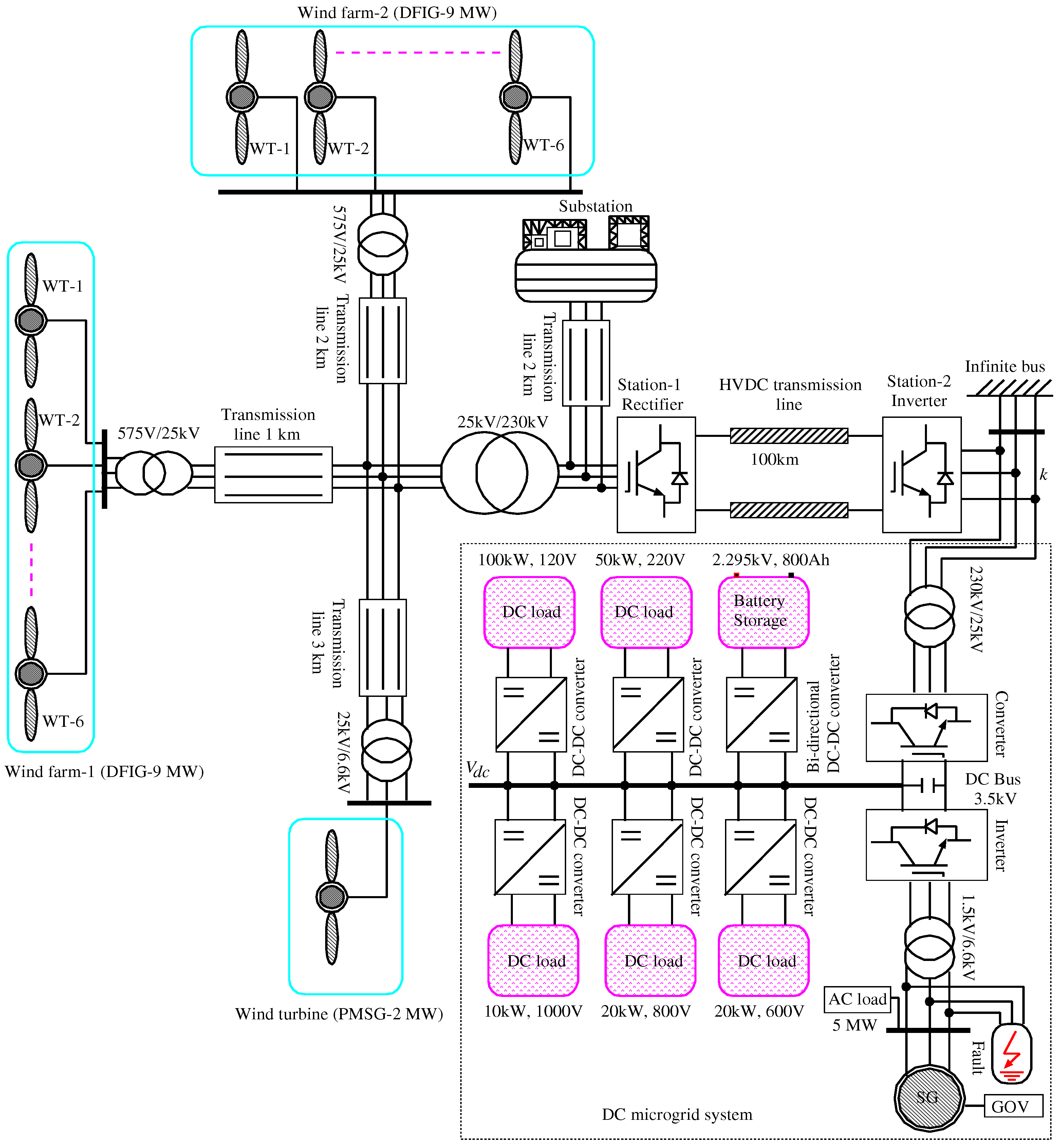
The proposed smart grid system is illustrated in Figure 1. As shown in this figure, two DFIG (18 MW) based offshore wind farms, which contain six turbines each and an offshore PMSG based wind turbine (rated 2 MW), are connected in a node through transmission lines. In addition, a substation (180 MVA, 230 kV) provides power to the grid through a 2 km transmission line. From the transformer (25 kV/230 kV), the power is provided to the power grid through an HVDC transmission line (100 km). The DC micro grid receives power through a step-down transformer (230 kV/100 kV). A VSC and a VSI control the DC bus voltage, grid voltage, and the power of the DC grid, and they are connected to an SG with an AC load (5 MW). An 800 Ah battery and various DC-loads such as (100 kW, 120 V), (50 kW, 220 V), (20 kW, 600 V), (20 kW, 800 V), and (10 kW, 1000 V) are the components of the proposed DC microgrid.
2.1. Wind Energy Conversion System
The maximum input power of the WECS can be expressed as [27]:
Wind turbine input torque is determined as:
The tip speed ratio is defined as . The power output and torque output of the wind turbine (i.e., input torque to the generator) are determined as:
The power coefficient is defined by the following equation:
The mathematical model of the PMSG is determined by the following equations:
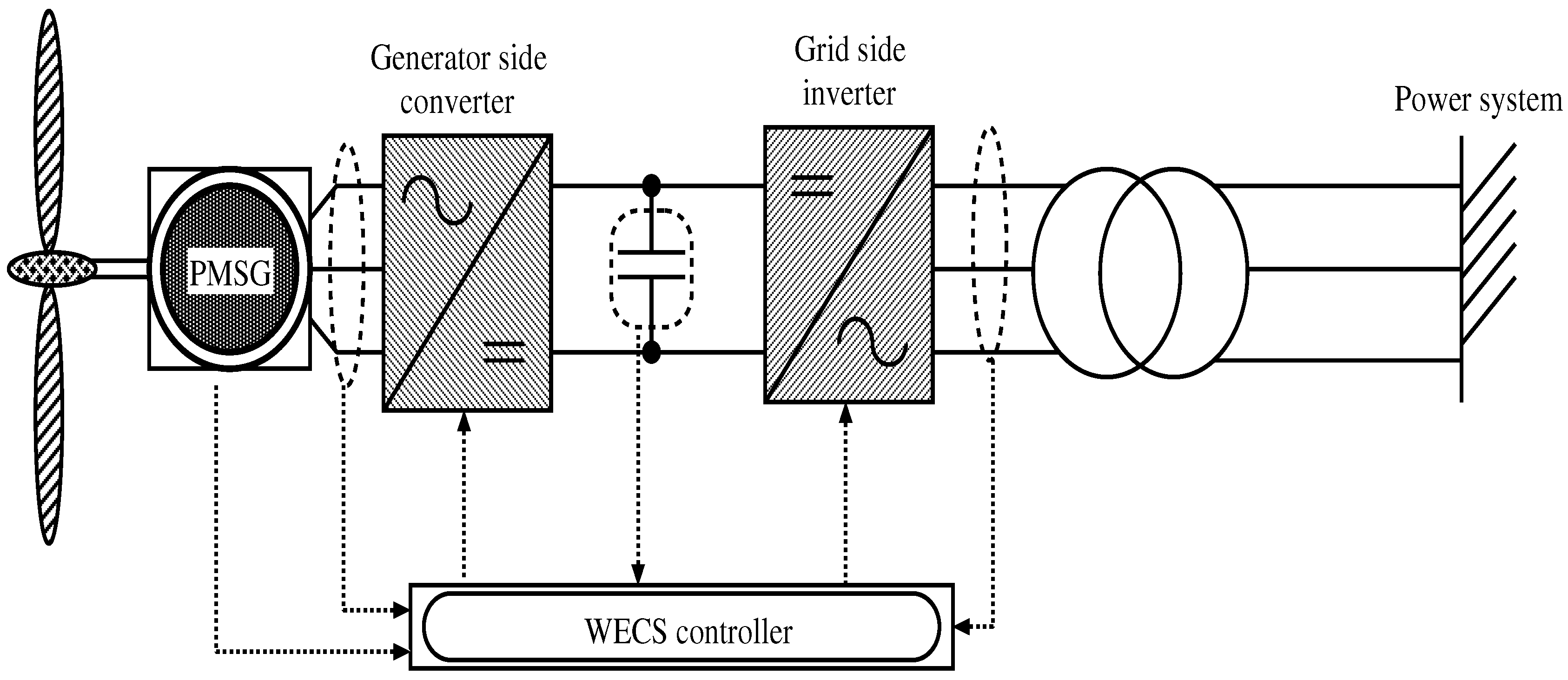
The PMSG based WECS is illustrated in Figure 2. It can be seen from this figure that the PMSG provides power to the grid through an AC–DC–AC power network.
The stator and rotor voltages and fluxes in a reference frame of a rotating DFIG are determined as [28]:
In addition, the motion equation of the generator is given by:
The active and reactive stator powers are determined as:
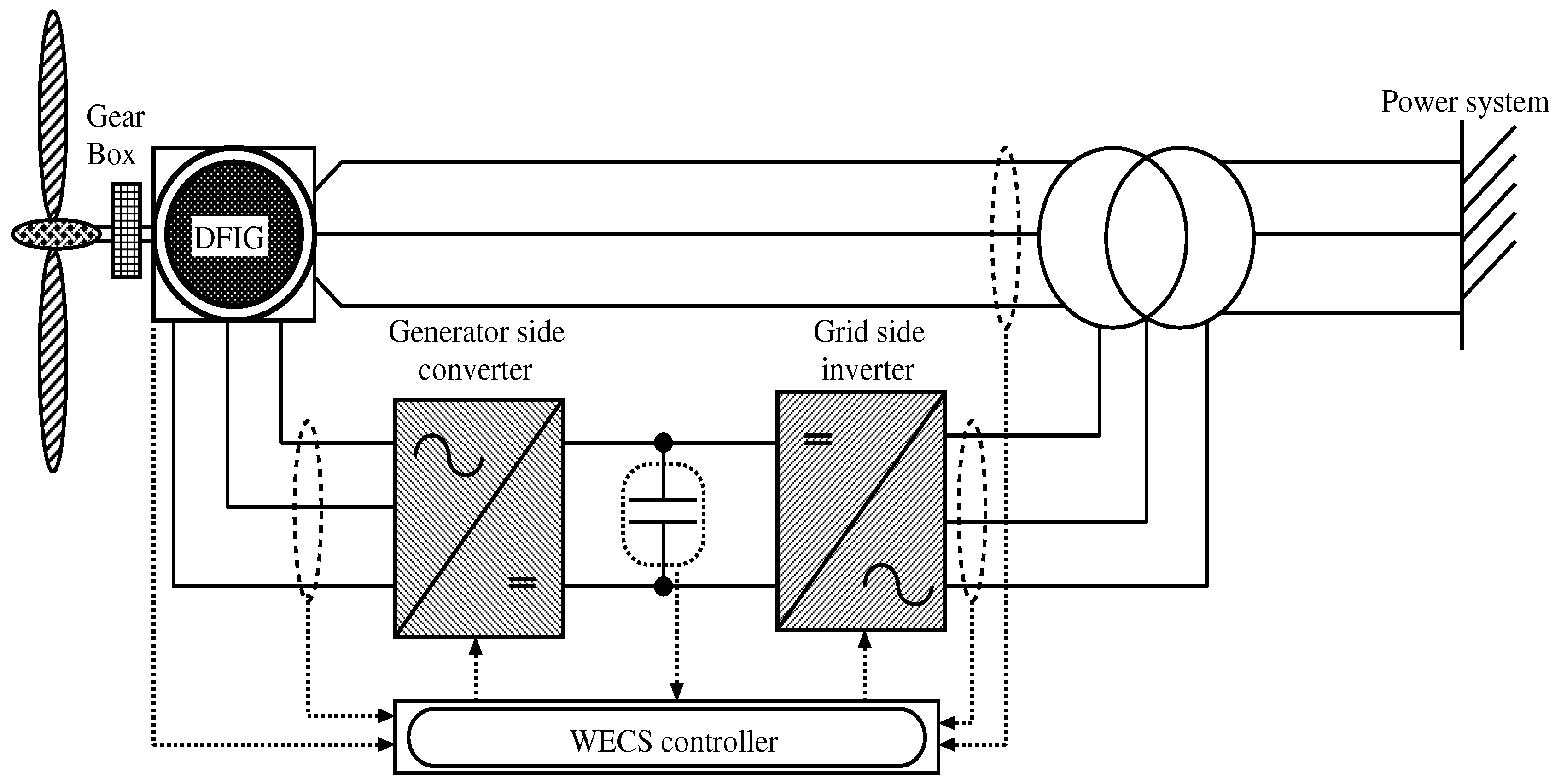
Figure 3 shows the DFIG based WECS. As can be seen in this figure, the stator of the DFIG is directly connected to the power grid, while a back-to-back three-phase voltage source inverter is connected to the grid on the other side.
Both DFIG and PMSG are the variable speed turbines that can perform MPPT operation. The MPPT control can achieve the maximum power from wind velocities, and the pitch angle control method can control the rotational speed of the wind turbine which are applied to the wind turbines.
2.2. HVDC Link, Battery and Diesel Generator Systems
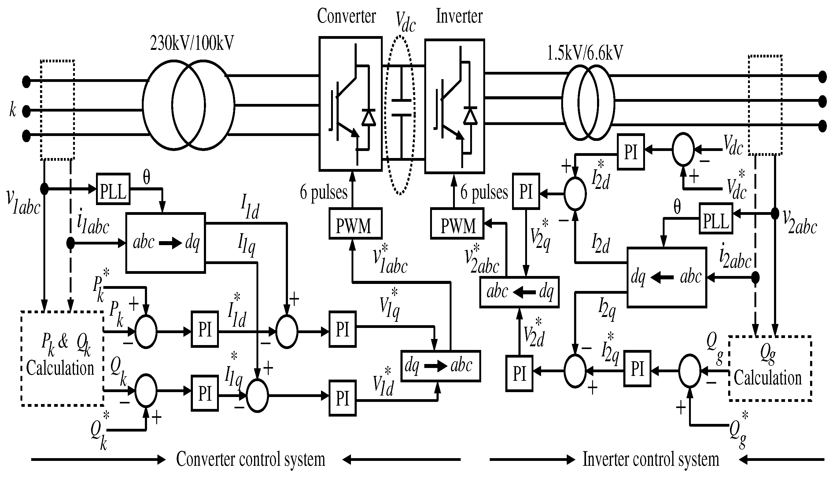
An AC transmission system may experience a limitation when the power output requires being supplied from a long distance. For a long distance of power transmission, an HVDC transmission provides more advantages than the AC transmission system. The HVDC system is an AC to DC power conversion with the rectifier, and the converted DC power transmits to the power grid through the HVDC cable. The DC power reconverts into the AC power using an inverter. The VSC-HVDC transmission system can divided into two main parts, the converters, at both ends of the system, and the transmission cable between them. The main components of these two parts are AC and DC side harmonic filters, transformers, IGBT converters, phase reactors, DC cable, auxiliary power set, protection, and control devices [29]. The configuration of the VSC-HVDC system is shown in Figure 4. A forced-commutated VSC-HVDC has been considered in this paper. The main characteristic of the VSC-HVDC transmission is its ability to independently control the active and reactive flow at each of the AC systems. The control system of the VSC is shown in [30].
The diesel generator model consists of a synchronous generator model with AVR and governor (GOV) controls. The BESS model is designed by charge and discharge characteristics of the BESS. A Lead-Acid battery has been considered in this paper. The SOC is calculated by the integration of the charge and discharge power of the BESS.
3. DC Microgrid Control System
Details on the control strategies of the DC micro grid system (dotted black rectangle (Figure 1)) are contained in this section. Power converters, BESS, and load control methodologies of the DC grid are described in this section.
3.1. Converter Control System
The power converter control system is described in this section. A step-down transformer (200 kV/3.5 kV) is connected to the converter (Figure 1). The relation between the voltage and current can be defined at point k in Figure 1 [31]:
The and flowing through the converter are as follows:
From Equations (20) and (21), the relation between powers and current components can be determined as:
If , then from Equations (18) and (19), the following relationship can be determined:
Finally, the active power, , and reactive power, flowing through the converter can be derived as:
From the above equations, the control system of the active and reactive powers is illustrated in Figure 5. Power converters control the active and reactive powers of the proposed power system. In Figure 5, the is compared with the actual value , and the error is the input of the PI controller, which determines (Equation (22)). The reference active power is set to the maximum power of the power sources. The reference is compared with the actual value , and the error is progressed through another PI controller which determines the value of (Equation (24)). The actual values and are determined from the three-phase current using the Park transformation, and the phase angle is detected by the PLL method. On the other hand, reactive power of the microgrid is also controlled by a similar method using two PI controllers to determine and (Equations (22) and (24)), respectively. From the axis voltage references and , three-phase voltage reference is calculated, which is the input of a PWM generator. The PWM generator provides six pulse signals for driving the IGBT gates.
3.2. Inverter Control System
The inverter controls the and of the power system. As can be seen in Figure 5, the d-axis current controls the , and the q-axis current controls the . The DC bus voltage reference is set to 3.5 kV while the reactive power command is set to zero for achieving the unity power factor operation. The converts the to reference frame which is detected from the three-phase voltage using the PLL method. Finally, the PWM generator produces the six pulses signal to drive the six IGBTs of the inverter.
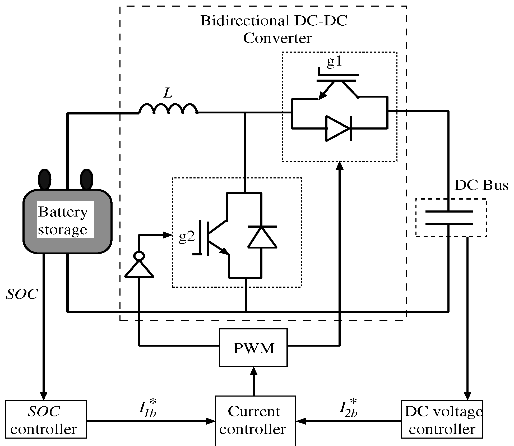
3.3. Battery Control System
The BESS controls the constant DC bus voltage that is performed by the bi-directional DC–DC chopper circuit. The control algorithm of the DC–DC chopper circuit is shown in Figure 6. The chopper circuit controls the DC bus voltage and SOC of the BESS. Details on the control systems of the chopper circuit are shown in Figure 7 and Figure 8. The bi-directional DC–DC chopper circuit controls the BESS operation during normal and line-fault conditions. The normal and fault operations can be detected from the AC-grid’s voltage (6.6 kV). When the AC-grid voltage ≥ 0.8 pu, which reflects the the normal operation condition. On the other hand, when the AC-grid voltage is < 0.8 pu, which refers to the fault operation condition.
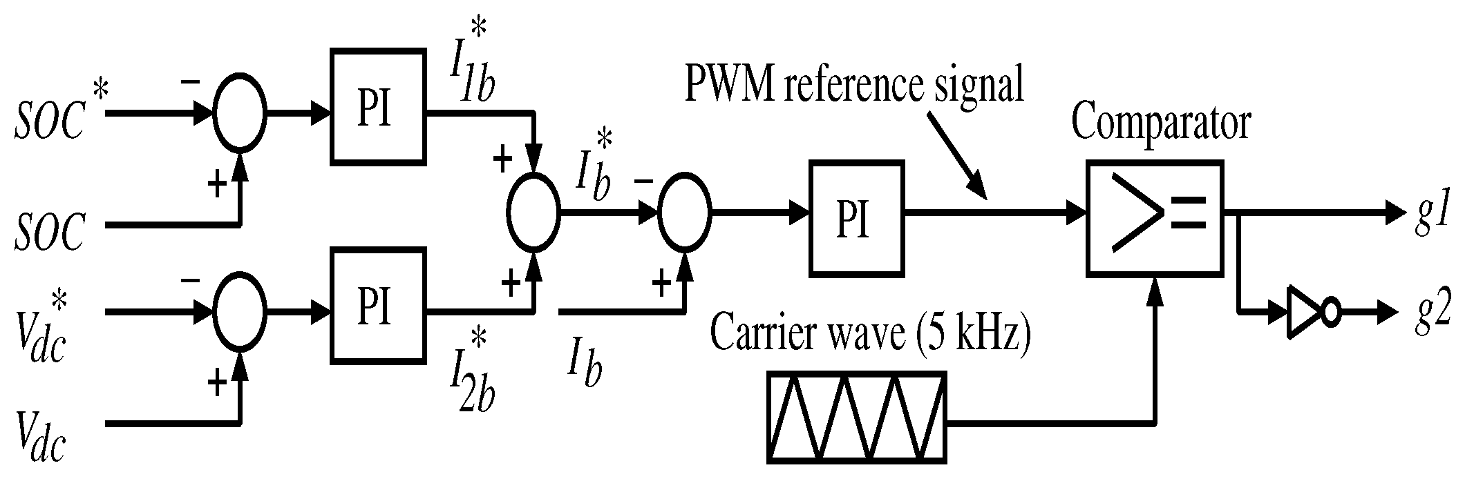
3.3.1. Control System for the Normal Operation
Figure 7 shows the control strategy of the chopper circuit for a normal operation condition. Errors of the (commanded value of the and actual value of the ), and the DC bus voltage (commanded value of the DC bus voltage and actual DC bus voltage) are inputs of PI controllers, which generates the commanded value of the battery current . The commanded value of the is set to 50%. The DC bus voltage command is set to 3.5 kV. The BESS current error (commanded battery current and actual battery current ) is an input of the PI controller. The output of the PI controller is compared with the triangular carrier wave to generate the gate signals ( and ) of the bidirectional chopper.
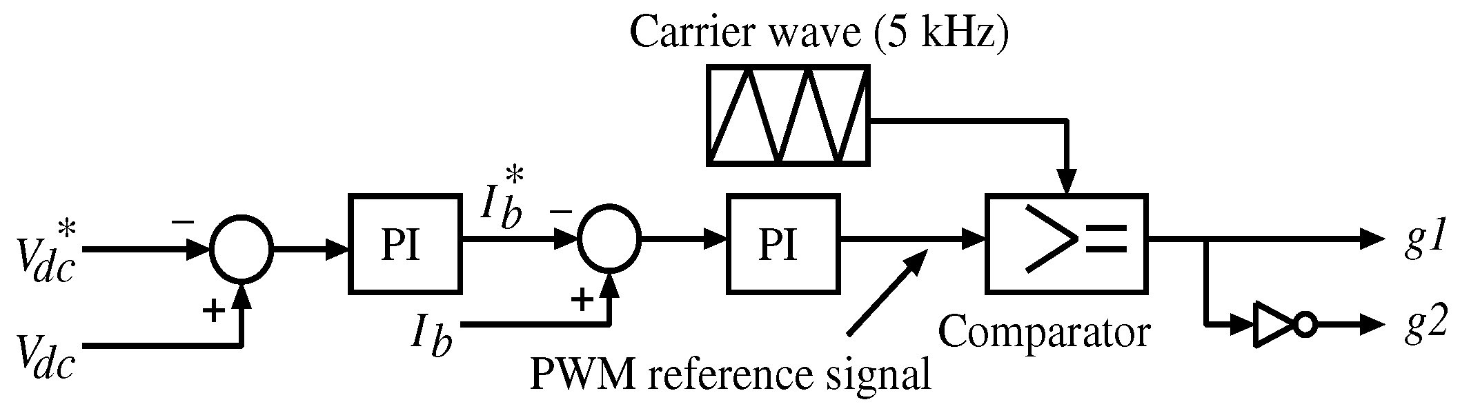
3.3.2. Control System of Fault Operation
Under the line fault condition, the BESS storage controls the DC bus transient voltage by using the bidirectional DC–DC chopper. During the line fault situation, a transient DC bus voltage is very difficult to control at a constant level by using a PI controller. The DC bus voltage control system during the line fault condition is shown in Figure 8. In this system, outputs of the DC bus voltage error, and the BESS current error are inputs of PI controllers which generate the PWM reference signal. The reference signal is compared with the triangular carrier wave to determine the DC–DC chopper gate signals.
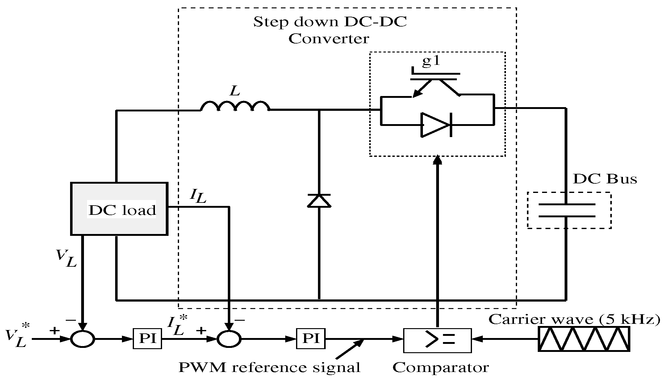
3.4. Control System of Load
A control system for different loads of the DC microgrid is illustrated in Figure 9. It is a step down DC–DC chopper circuit. In this figure, the voltage error of the load ( and ) is the input of the PI controller that generates the reference current signal for the load, . The error of the load current is the input of another PI controller which generates the reference PWM signal. The reference signal is compared with the triangular carrier wave to drive the DC–DC chopper circuit’s gate.
4. Simulation Results
Simulation parameters of the wind turbines and transmission lines are provided in Appendix A. To evaluate effectiveness of the proposed BESS based method, simulation results of the line fault situation are compared to the normal operation, and without a BESS based method. Simulation results are shown in Figure 10, Figure 11 and Figure 12.
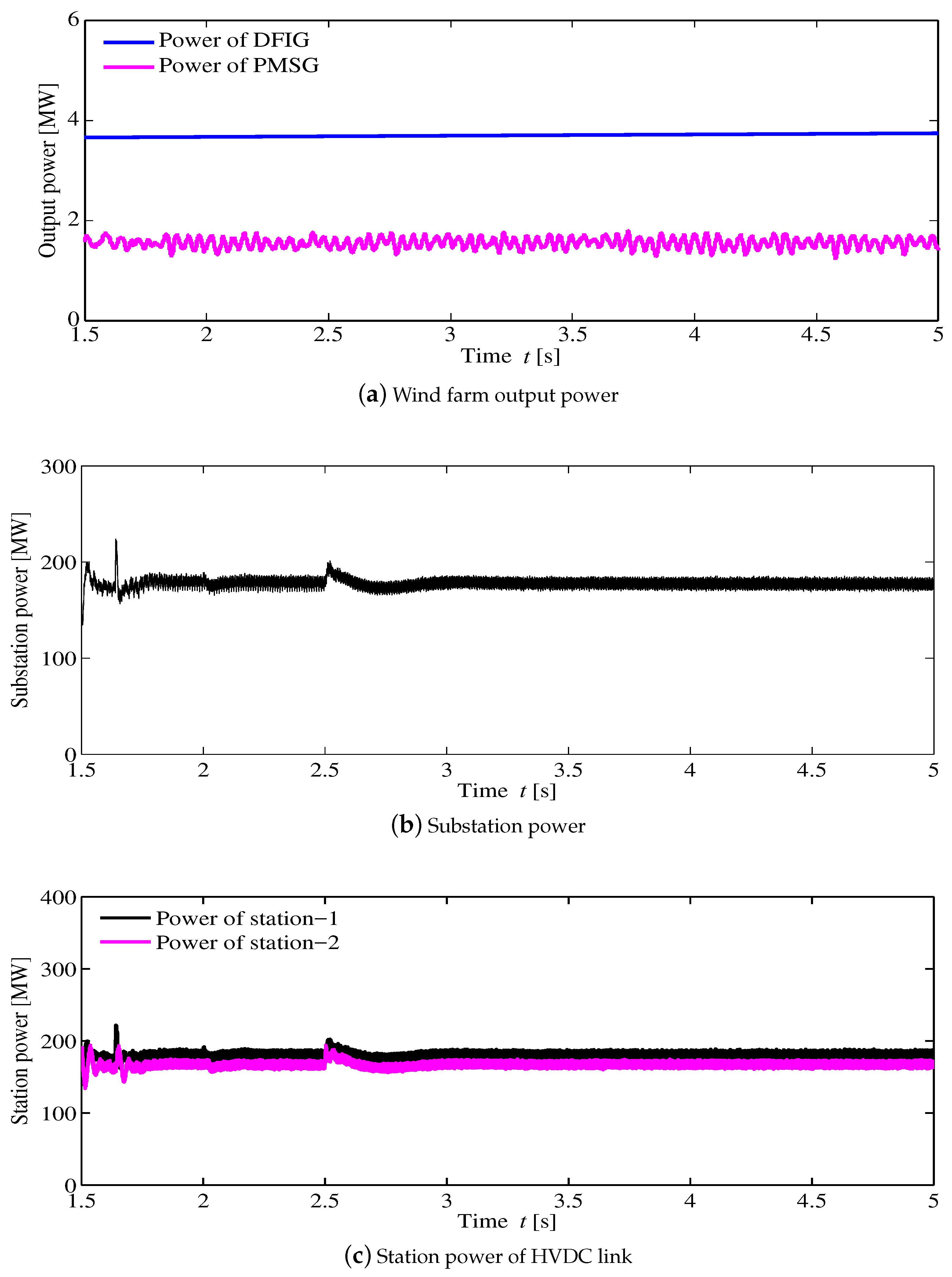
Figure 10 provides the power output of the proposed smart grid system. Power outputs of the DFIG based wind farms, and PMSG based wind turbine are shown in Figure 10a. Both DFIG based wind farms receive a constant (11 m/s) wind speed. Therefore, both wind farms provide a similar power output (Figure 10a). In addition, wind speed is constant at 11 m/s for the PMSG based wind turbine, and produces a constant power during the simulation. The power from the substation is illustrated in Figure 10b. All generated powers supply to the Station-1 (rectifier) of the HVDC-lines. From Station-1, the HVDC-lines supply power to the Station-2 (inverter). Figure 10c illustrates the station powers of the HVDC transmission lines, where the power output of Station-1 is similar to that of Station-2.
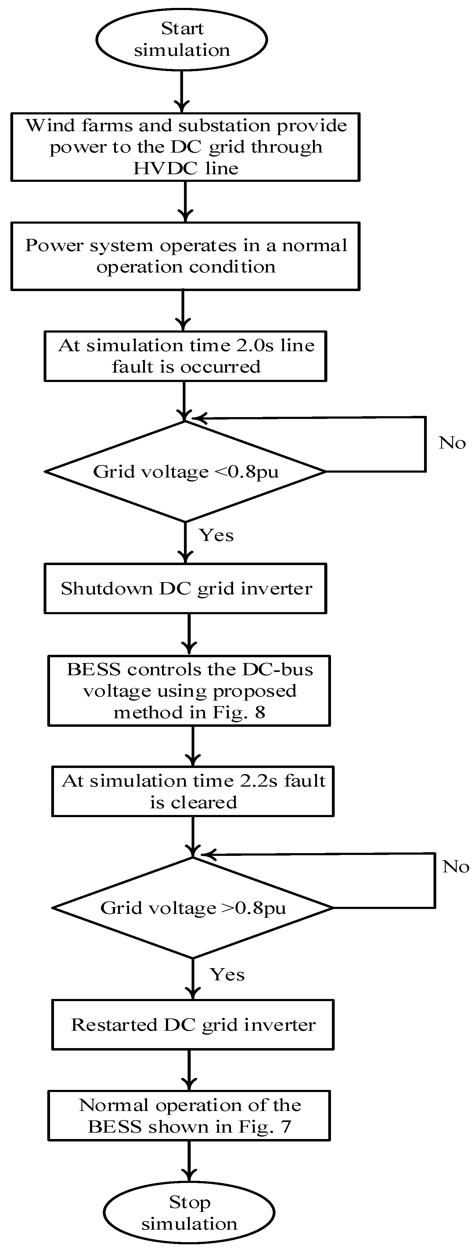
In this simulation, the three-phase line to ground fault occurred at the end of the transmission line. The simulation steps during the fault time are:
- t = 2.0 s is the three-phase line to ground-fault starting time.
- The gate signals of the DC grid inverter are shutdown when the grid voltage is less than 0.8 pu.
- The line fault is cleared at t = 2.2 s.
- The gate signals of the inverter are re-started, when the AC-grid voltage is above 0.8 pu.
A flowchart of the proposed line fault control algorithm is illustrated in Figure 11. In this study, the fault situation is protected by detecting the grid voltage, and a BESS controls the DC-bus over-voltages. This control scheme is also known as the voltage based fault protection method. A comparison analysis of different fault protection methods of the DC microgrid is summarized in Table 1 [32,33].
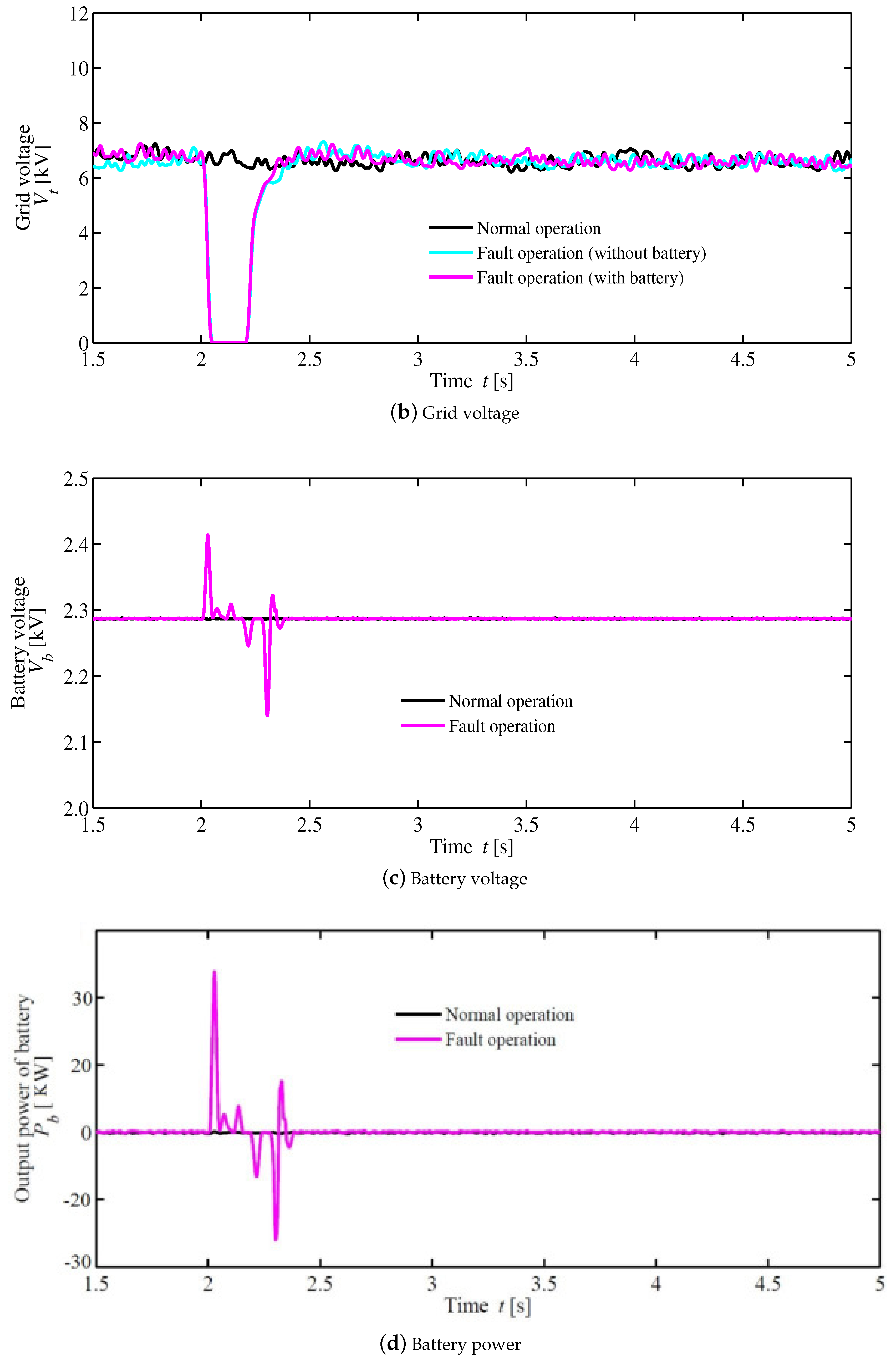
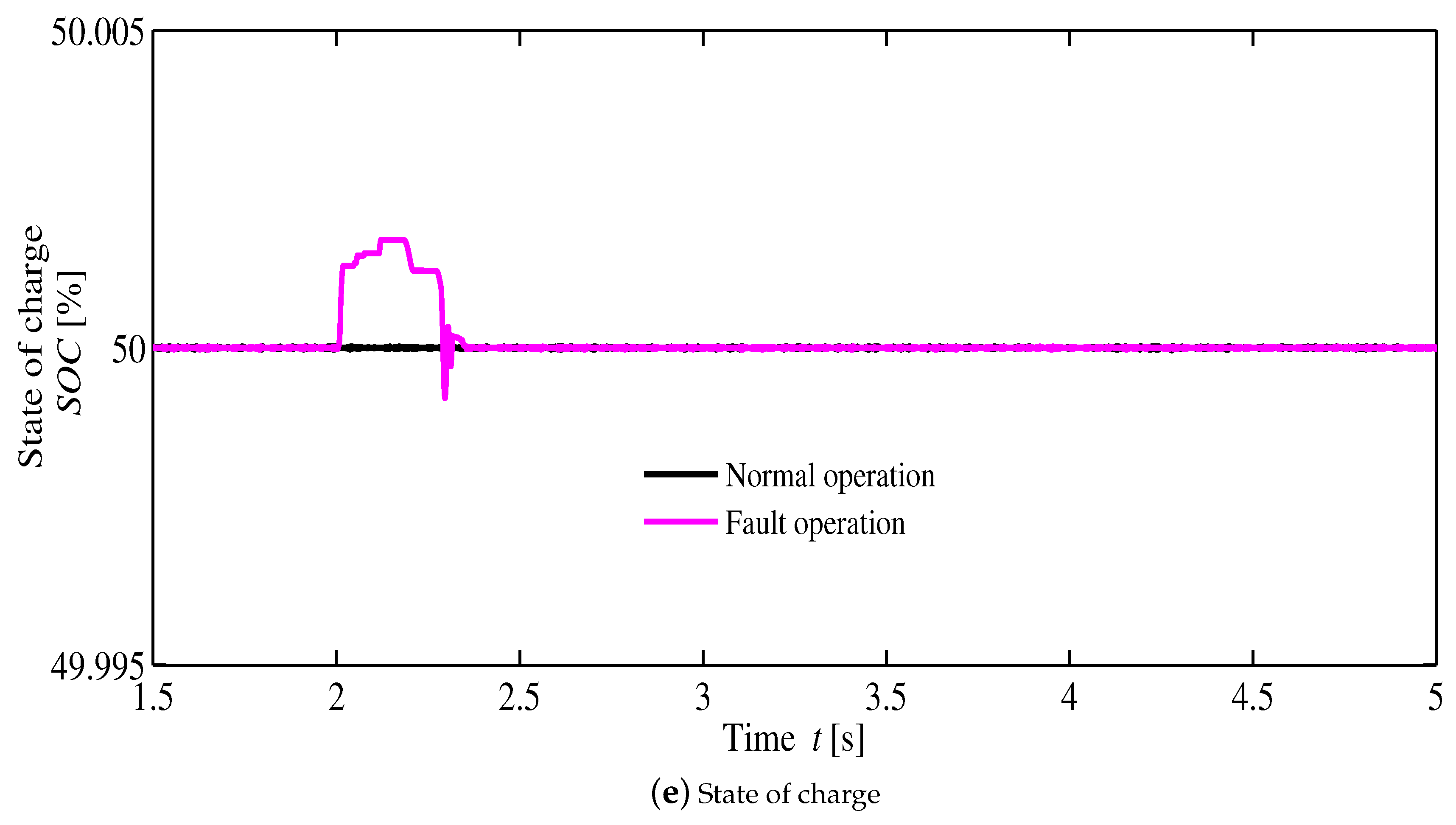
Figure 12 shows comparison analyses for different operations of the DC micro grid. Figure 12a shows the DC bus voltage of the DC micro grid. In this figure, it can be seen that the BESS can control the DC bus voltage, similar to the normal operation during the system fault situation while there is a large voltage deviation without a BESS based method. It may damage the DC-link capacitor because the DC-link capacitor can tolerate a voltage deviation from 0.85 pu to 1.12 pu. Therefore, the proposed BESS based method ensures the DC grid stability at the line fault situation. The grid voltage is shown in Figure 12b. The grid voltage drops to the zero when a line fault occurs, and is restored when the fault is cleared. Different parameters of the BESS are shown in Figure 12c–e. The BESS voltage is shown in Figure 12c. In this figure, the voltage of the BESS is increased when the fault occurs for controlling the DC bus overvoltage, and then the voltage of the battery is dropped and BESS provides power to control the voltage dip of the DC bus. The power output of the BESS is shown in Figure 12d. In this figure, it can be seen that the BESS absorbs power when the fault occurs (2.0 s); then, the battery provides power to the DC grid to control the DC bus voltage. As shown in Figure 12e, the SOC increases during the fault time and then settles to 50% when the fault is cleared. The SOC controller (Figure 7) maintains the SOC of the BESS at 50%.
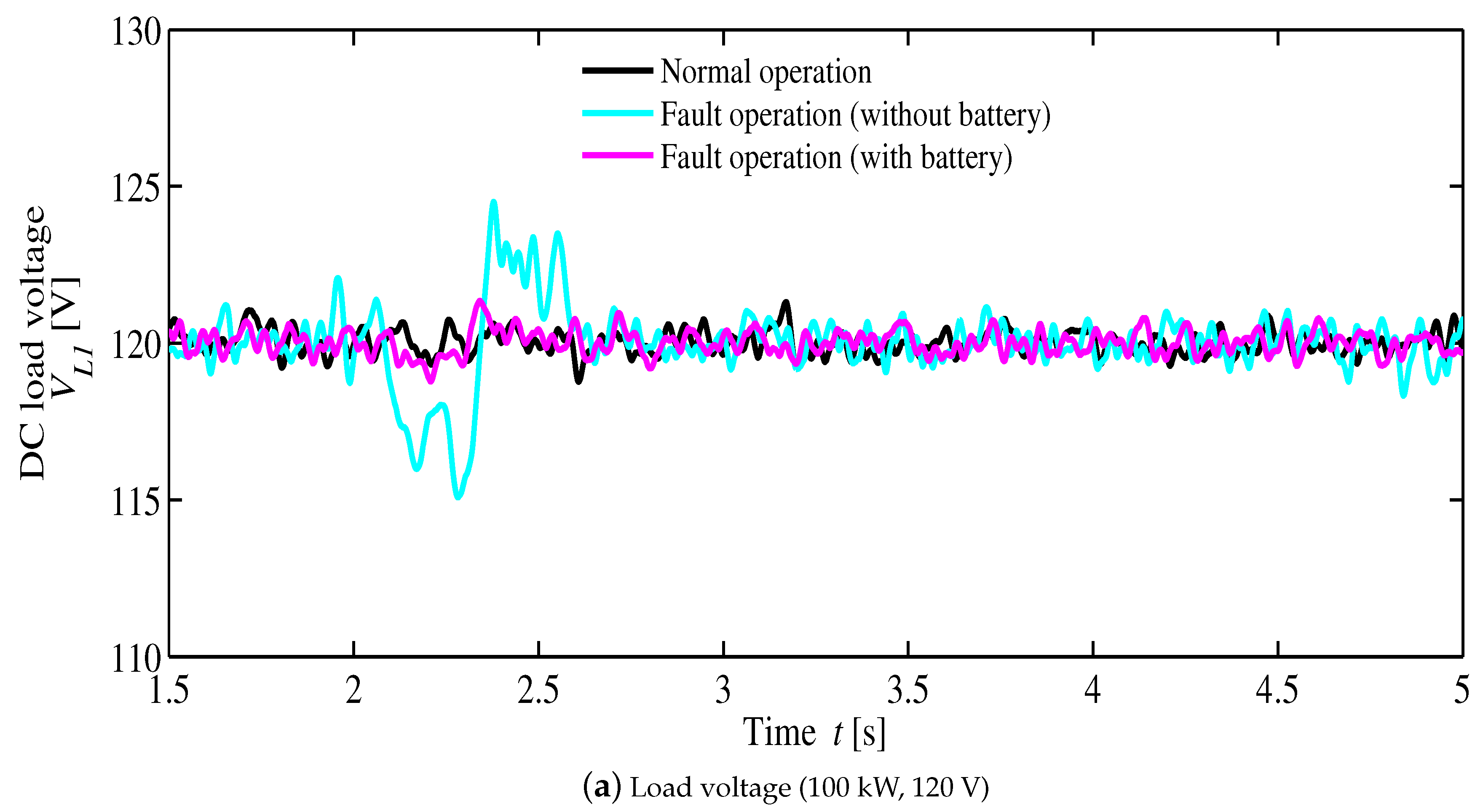
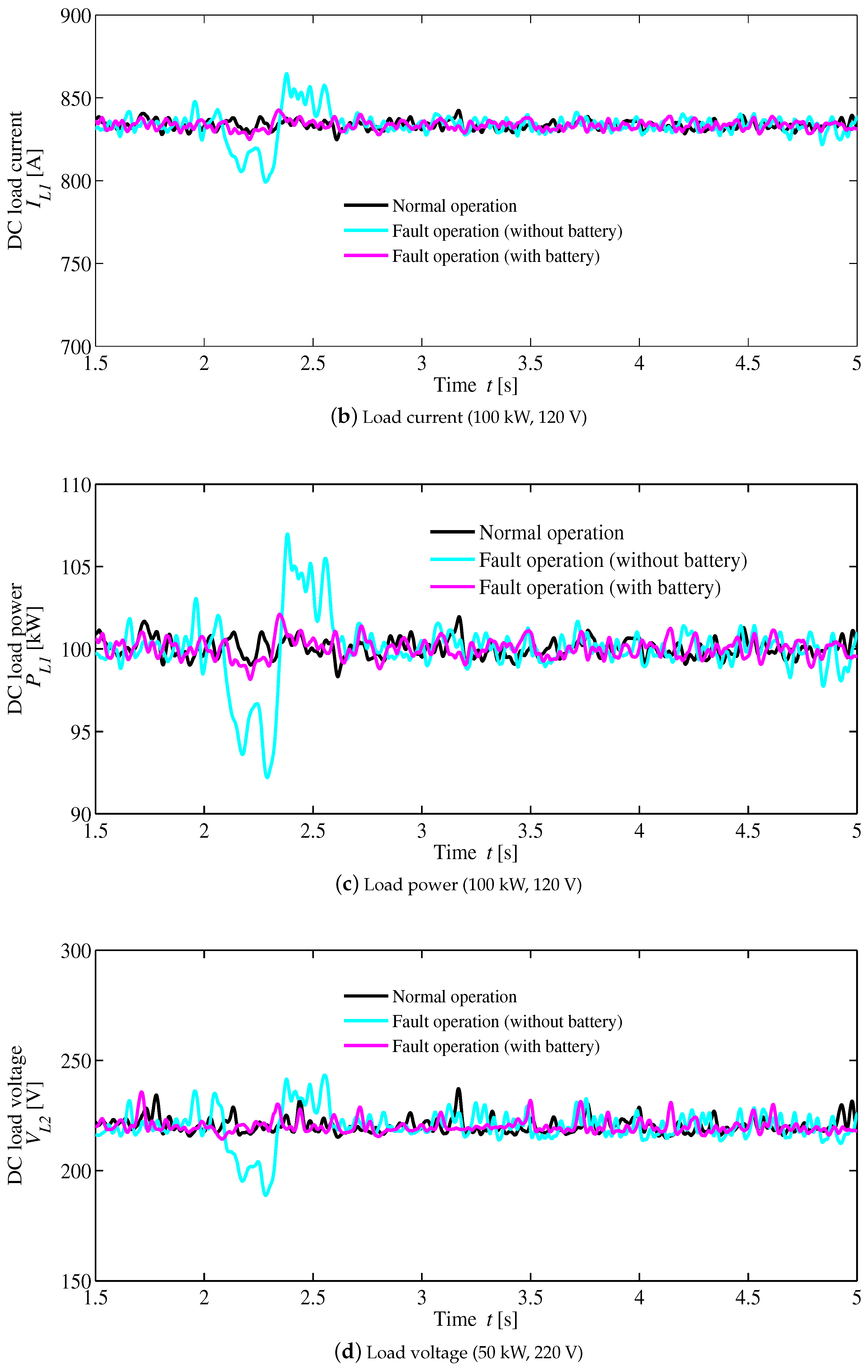
Different load voltages, currents, and powers are shown in Figure 13a–l. Figure 13a shows the voltage () of the (100 kW, 120 V) load. The current () of the (100 kW, 120 V) load is shown in Figure 13b, and the power () of the (100 kW, 120 V) load is illustrated in Figure 13c. Based on these figures, when a line fault occurs, the BESS-based proposed method can control voltage, current, and power, similarly to the normal operation. Hence, there are large voltage, current, and power fluctuations without a BESS based method, which may damage the electronics of the DC grid system. Figure 13d illustrates the voltage () of the (50 kW, 220 V) load, and Figure 13e shows the current () of the same load. The power () of the (50 kW, 220 V) load is illustrated in Figure 13f. Based on these figures, the proposed BESS-based method ensures protection of the load at the line fault situation because it diminishes the fluctuations in voltage, current, and power.
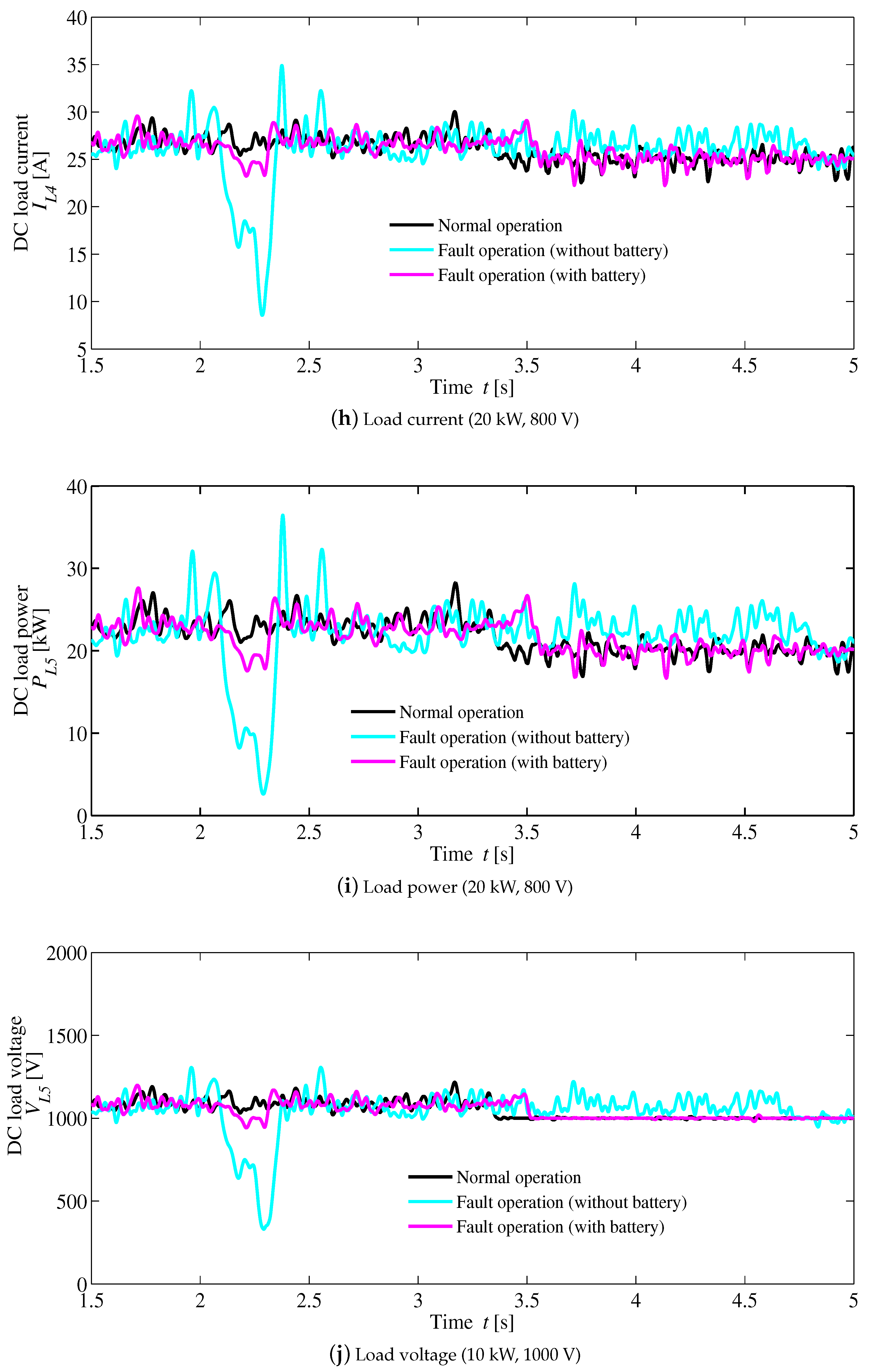
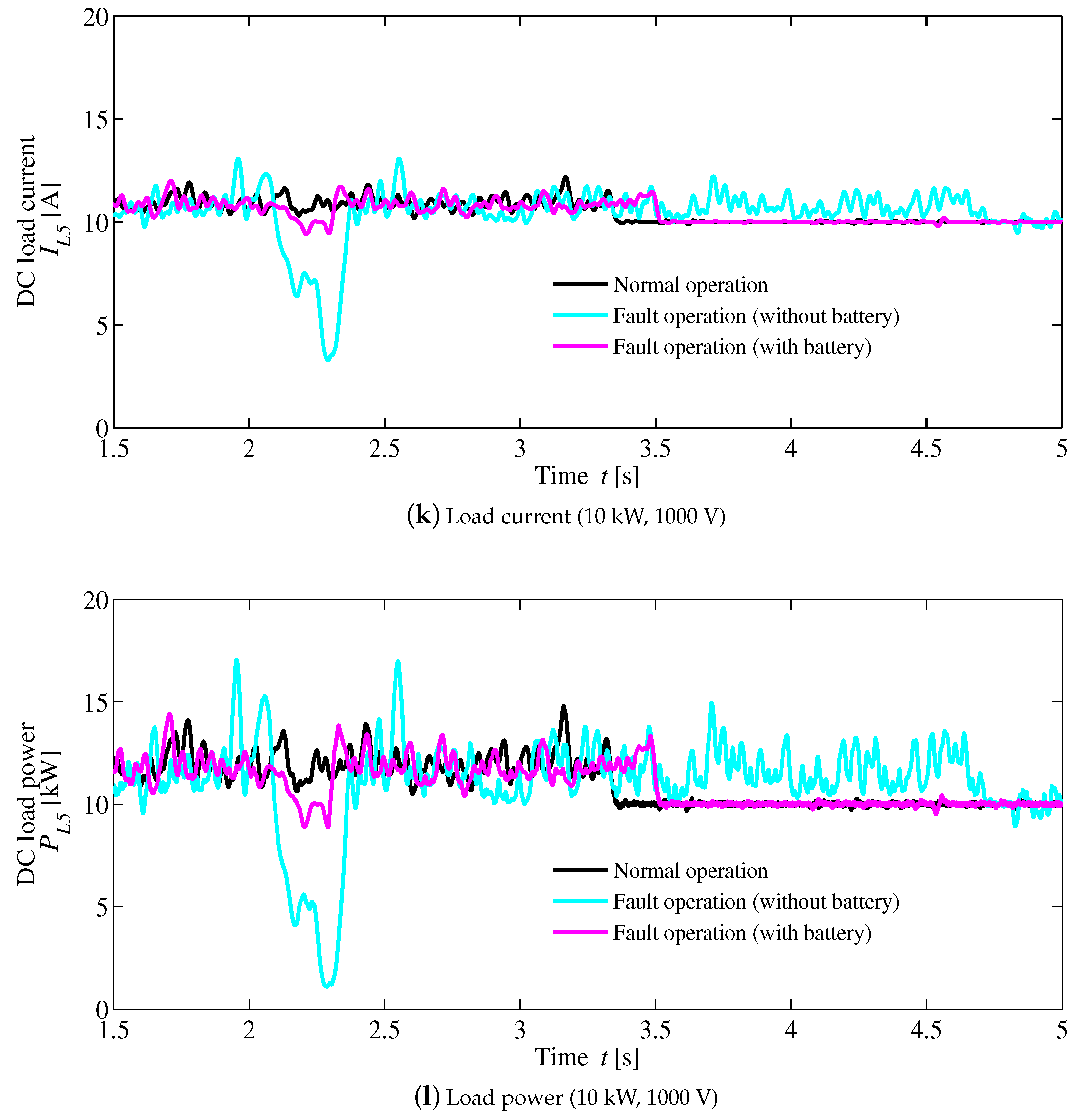
Figure 13g shows the voltage () of the (20 kW, 800 V) load. The current () of the (20 kW, 800 V) load is illustrated in Figure 13h, and the power () of the (20 kW, 800 V) load is depicted in Figure 13i. Based on these figures, the non-BESS based method cannot control the voltage, current, and power at the line fault situation. The voltage, current, and power deviations are very large without a BESS based method, which may cause the DC micro grid to become unstable, and further damage important household electronics’ devices. Simulation results of the (20 kW, 600 V) load show similar behaviors to the (20 kW, 800 V) load. This is why the simulation results of the (20 kW, 600 V) load are not shown here. The (10 kW, 1000 V) load voltage () is represented in Figure 13j, and the current () of the (10 kW, 1000 V) load is shown in Figure 13k. Figure 13l illustrates the power () of the (10 kW, 1000 V) load. Based on these figures, the proposed BESS based method ensures system stability during a line fault. From the above simulation analyses, the proposed method shows quite similar behaviors to normal operation conditions, and fluctuation ranges are around zero for all loads in the DC grid. A comparison of fluctuation voltages, currents, and powers for different loads is shown in Table 2. In this table, upward fluctuations are indicated by the positive sign, and the downward fluctuations are denoted by the negative sign. The table data confirm that severe voltages, currents, and powers fluctuations occur without a BESS based method.
5. Conclusions
Stable operation of a DC microgrid system operated using a BESS is studied. A DC microgrid has some advantages as compared to the AC grid system. The BESS of the DC microgrid controls the DC bus’s over-voltage during a line fault, which can protect different loads and other components of the DC microgrid. Most of the DC microgrid systems already installed a BESS for ensuring an uninterruptible power supply. Therefore, additional energy storage system is not required to install for controlling the line fault condition. In this paper, a three-phase line to ground fault considered at the end of the transmission line. Simulation results are compared to the normal operation, without a BESS based approach, and the proposed BESS based method. From the simulation results, large voltage, current, and power dips were caused without a BESS based method, which can damage the important electronic devices. Based on the simulations, stable operation can be executed by the proposed BESS-based method. In addition, control strategies for the wind farms, HVDC, and various loads of the DC microgrid are provided.
Author Contributions
Conceptualization, A.M.H. and T.S.; Methodology, A.M.H.; Validation, A.M.H. and H.M.; Writing—Original Draft Preparation, A.M.H.; Writing—Review & Editing, A.M.H. and S.S.
Funding
This research received no external funding.
Conflicts of Interest
The authors declare no conflict of interest.
Nomenclature
| Direct current | |
| Distributed renewable energy sources | |
| Alternating current | |
| Distributed generator | |
| multi-modular converter | |
| High voltage DC | |
| Low voltage DC | |
| Voltage source converter | |
| Doubly-fed induction generator | |
| Permanent magnet synchronous generator | |
| Battery energy storage system | |
| Voltage source inverter | |
| synchronous generator | |
| Wind turbine blade radius | |
| Wind speed | |
| Air density | |
| Turbine input torque | |
| Rotational speed of the wind turbine | |
| Tip speed ratio | |
| Power coefficient | |
| Pitch angle | |
| d-axis voltage | |
| q-axis voltage | |
| d-axis current | |
| q-axis current | |
| Stator resistance | |
| d-axis inductance | |
| q-axis inductance | |
| Electrical rotational speed | |
| K | Permanent magnet flux |
| p | Number of pole pairs |
| Electromagnetic torque | |
| Magnetic flux | |
| v | Voltage |
| i | Current |
| s | Stator quantity |
| r | Rotor quantity |
| Stator self-inductance | |
| Rotor self-inductance | |
| Mutual inductance | |
| Rotor slip frequency | |
| Base angular frequency | |
| Stator resistance | |
| Rotor resistance | |
| D | Rotational damping |
| Equivalent inertia | |
| Load torque | |
| Mechanical rotational speed | |
| MPPT | Maximum power point tracking |
| PCC | Point of common coupling |
| SOC | State of charge |
| IGBT | Insulated gate bipolar transistor |
| AVR | Automatic voltage regulation |
| Active power reference | |
| DC bus voltage | |
| Reactive power of wind turbine | |
| Phase angle | |
| Reference load voltage | |
| Actual load voltage |
Appendix A
Simulation parameters are given as follows:
Parameters of the PMSG wind turbine: blade radius = 39 m, inertia = 300,000 kg·m, air density = 1.205 kg/m, rated wind speed = 12 m/s, rated power = 2 MW, pair of poles p = 11, stator resistance = 50 , d-axis inductance = 0.0055 H, q-axis inductance = 0.00375 H, field flux K = 135.25 V·s/rad. Parameters of the DFIG wind turbine: Stator resistance = 0.023 pu, stator inductance = 0.18 pu, rotor resistance = 0.016 pu, rotor inductance = 0.16 pu, mutual inductance = 2.9 pu, inertia constant = 0.685 pu, friction factor F = 0.01 pu, pole pairs p = 3, rated power = 1.5 MW, blade radius = 40 m, rated wind speed = 15 m/s. Transmission line: Resistances: = 0.1153, 0.413 /km, Inductances: = 1.05, 3.32 mH/km, Capacitances: = 11.33, 5.01 nF/km. Battery Energy Storage System: Nominal voltage per cell: 50V, total cell: 46, Rated capacity: 800 Ah, Initial state of charge: 50%.
References
- Shi, R.; Semsar, S.; Lehn, P.W. Constant current fast charging of electric vehicles via DC grid using dual inverter drive. IEEE Trans. Ind. Electron. 2017, 64, 6940–6949. [Google Scholar] [CrossRef]
- Pascal, T.P.; Badel, A.; Auran, G. Superconducting fault current limiter for ship grid simulation and demonstration. IEEE Trans. Appl. Supercond. 2017, 27, 1–5. [Google Scholar] [CrossRef]
- Miyazato, Y.; Tobaru, S.; Uchida, K.; Muarapaz, C.C.; Howlader, A.M.; Senjyu, T. Multi-objective optimization for equipment capacity in Off-grid smart house. Sustainability 2017, 9, 117. [Google Scholar] [CrossRef]
- Savage, P.; Nordhaus, R.R.; Jamieson, S.P. DC Microgrids: Benefits and Barriers from Silos to Systems: Issues in Clean Energy and Climate Change; Yale Publications: New Haven, CT, USA, 2010; p. 51. [Google Scholar]
- Gharavi, H.; Ghafurian, R. Smart grid: The electric energy system of the future. Proc. IEEE 2011, 99, 917–921. [Google Scholar] [CrossRef]
- Dongxiao, N.; Di, P.; Shuyu, D. Ultra-short-term wind-power forecasting based on the weighted random forest optimized by the niche immune lion algorithm. Energies 2018, 11, 1098. [Google Scholar]
- Sheng, L.; Zhinong, W.; Yanan, M. Fuzzy load-shedding strategy considering photovoltaic output fluctuation characteristics and static voltage stability. Energies 2018, 11, 779. [Google Scholar]
- Guerrero, J.M.; Vasquez, J.C.; Matas, J.; Vicuna, L.G.; Castilla, M. Hierarchical control of droop-controlled AC and DC microgrids A general approach toward standardization. IEEE Trans. Ind. Electron. 2011, 58, 158–172. [Google Scholar] [CrossRef]
- Kollimalla, S.K.; Mishra, M.K.; Ukil, A. DC grid voltage regulation using new HESS control strategy. IEEE Trans. Sustain. Energy 2017, 8, 772–781. [Google Scholar] [CrossRef]
- Davari, M.; Mohamed, Y.A.I. Robust DC-link voltage control of a full-scale PMSG wind turbine for effective integration in DC Grids. IEEE Trans. Power Electron. 2017, 32, 4021–4035. [Google Scholar] [CrossRef]
- Hao, Y.; Zhao, H.; Wu, Q. Coordinated control of multi-terminal DC grid for wind power integration. In Proceedings of the 2016 IEEE PES Asia-Pacific Power and Energy Engineering Conference (APPEEC), Xi’an, China, 25–28 October 2016; pp. 702–706. [Google Scholar]
- Sanz, I.M.; Chaudhuri, B.; Strbac, G. Inertial response from offshore wind farms connected through DC grids. In Proceedings of the 2016 IEEE Power and Energy Society General Meeting (PESGM), Boston, MA, USA, 17–21 July 2016; p. 1. [Google Scholar]
- Jovcic, D.; Zhang, H. Dual channel control with DC fault ride through for MMC-based, Isolated DC/DC Converter. IEEE Trans. Power Deliv. 2017, 32, 1574–1582. [Google Scholar] [CrossRef]
- Kontos, E.; Bauer, P. Reactor design for DC fault ride-through in MMC-based multi-terminal HVDC grids. In Proceedings of the 2016 IEEE 2nd Annual Southern Power Electronics Conference (SPEC), Auckland, New Zealand, 5–8 December 2016; pp. 1–6. [Google Scholar]
- Mokhberdoran, A.; Carvalho, A.; Silva, N.; Leite, H.; Carrapatoso, A. Application study of superconducting fault current limiters in meshed HVDC grids protected by fast protection relays. Electr. Power Syst. Res. 2017, 143, 292–302. [Google Scholar] [CrossRef]
- Tzelepis, D.; Rousis, A.O.; Dysko, A.; Booth, C. Enhanced DC voltage control strategy for fault management of a VSC-HVDC connected offshore wind farm. In Proceedings of the 5th IET International Conference on Renewable Power Generation (RPG), London, UK, 21–23 September 2016; pp. 1–6. [Google Scholar]
- Daoud, M.I.; Massoud, A.M.; Abdel–Khalik, A.S.; Elserougi, A.; Ahmed, S. A flywheel energy storage system for fault ride through support of grid-connected VSC HVDC-based offshore wind farms. IEEE Trans. Power Syst. 2016, 31, 1671–1680. [Google Scholar] [CrossRef]
- Howlader, A.M.; Senjyu, T.; Saber, A.Y. An integrated power smoothing control for a grid-interactive wind farm considering wake effects. IEEE Syst. J. 2015, 9, 954–965. [Google Scholar] [CrossRef]
- Howlader, A.M.; Urasaki, N.; Saber, A.Y. Control strategies for wind-farm-based smart grid system. IEEE Trans. Ind. Appl. 2014, 50, 3591–3601. [Google Scholar] [CrossRef]
- Guo, W. Overview and development progress of a 1-MVA/1-MJ superconducting fault current limiter-magnetic energy storage system. IEEE Trans. Appl. Supercond. 2016, 26, 1–5. [Google Scholar] [CrossRef]
- Taj, T.A.; Hasanien, H.M.; Alolah, A.I.; Muyeen, S.M. Transient stability enhancement of a grid-connected wind farm using an adaptive neuro-fuzzy controlled-flywheel energy storage system. IET Renew. Power Gener. 2015, 9, 792–800. [Google Scholar] [CrossRef] [Green Version]
- Shi, M.X.; Chong, L. Line-to-Line Fault Analysis and Location in a VSC-Based Low-Voltage DC Distribution Network. Energies 2018, 11, 536. [Google Scholar] [Green Version]
- Yu, M.; Wang, Y.; Zhang, L.; Zhang, Z. DC short circuit fault analysis and protection of ring type DC microgrid. In Proceedings of the 2016 IEEE 8th International Power Electronics and Motion Control Conference (IPEMC-ECCE Asia), Hefei, China, 22–26 May 2016; pp. 1694–1700. [Google Scholar]
- Park, J.D.; Candelaria, J.; Ma, L.; Dunn, K. DC ring-bus microgrid fault protection and identification of fault Location. IEEE Trans. Power Deliv. 2013, 28, 2574–2584. [Google Scholar] [CrossRef]
- Santos, R.C.; Blond, S.L.; Coury, D.B.; Aggarwal, R.K. A novel and comprehensive single terminal ANN based decision support for relaying of VSC based HVDC links. Electr. Power Syst. Res. 2016, 141, 333–343. [Google Scholar] [CrossRef] [Green Version]
- Ikema, H.; Matayoshi, H.; Howlader, A.M.; Senjyu, T.; Funabashi, T. MTDC transmission systems including dc resonant semiconductor breaker. In Proceedings of the 2015 International Symposium on Smart Electric Distribution Systems and Technologies (EDST), Vienna, Austria, 8–11 September 2015; pp. 442–446. [Google Scholar]
- Howlader, A.M.; Urasaki, N.; Senjyu, T.; Uehara, A.; Yona, A.; Saber, A.Y. Output power smoothing of wind turbine generation system for the 2-MW permanent magnet synchronous generators. In Proceedings of the 2010 International Conference on Electrical Machines and Systems, Incheon, Korea, 10–13 October 2010; pp. 452–457. [Google Scholar]
- Zheng, D.I.; Ouyang, J.; Xiong, X.; Xiao, C.; Mengyang, L. A System Transient Stability Enhancement Control Method Using Doubly Fed Induction Generator Wind Turbine with Considering Its Power Constraints. Energies 2018, 11, 945. [Google Scholar] [CrossRef]
- Schettler, F.; Huang, H.; Christl, N. HVDC transmission systems using voltage source converters-design and applications. In Proceedings of the IEEE Power Engineering Society Summer Meeting, Seattle, WA, USA, 16–20 July 2000. [Google Scholar]
- Renaudin, F. Integration and Stability of a Large Offshore Wind Farm with HVDC Transmission in the Norwegian Power System; Institutt for Elkraftteknikk: Ålesund, Norway, 2009. [Google Scholar]
- Muyeen, S.M.; Ali, M.H.; Takahashi, R.; Murata, T.; Tamura, J. Damping of blade-shaft torsional oscillations of wind turbine generator system. Electr. Power Compon. Syst. 2018, 36, 195–211. [Google Scholar] [CrossRef]
- Monadi, M.; Zamani, M.A.; Candela, J.I.; Luna, A.; Rodriguez, P. Protection of AC and DC distribution systems Embedding distributed energy resources: A comparative review and analysis. Renew. Sustain. Energy Rev. 2015, 51, 1578–1593. [Google Scholar] [CrossRef] [Green Version]
- Zhang, L.; Tai, N.; Huang, W. A review on protection of DC microgrids. J. Mod. Power Syst. Clean Energy 2018, 6, 1–15. [Google Scholar] [CrossRef]
Figure 1.
The proposed smart grid system.

Figure 2.
PMSG based wind energy conversion system.

Figure 3.
DFIG based wind energy conversion system.

Figure 4.
Configuration of a VSC-HVDC system.

Figure 5.
Power converter control system for the microgrid.

Figure 6.
Control system of the battery and DC–DC chopper.

Figure 7.
Battery control system in normal operation.

Figure 8.
Constant DC bus voltage control system for fault condition.

Figure 9.
Power converter control system for the microgrid.

Figure 10.
Simulation results of the generated powers.

Figure 11.
Flowchart of the proposed control algorithm.

Figure 12.
Simulation results of DC bus voltage, grid voltage, and battery parameters.


Figure 13.
Simulation results of the different loads.


Table 1.
Summary of fault protection methods in the DC microgrid.
| Protection Method | Detection Scheme | Threshold | Comments |
|---|---|---|---|
| Voltage based method | The fault is detected by the voltage, dv/dt. | Depends on the voltage setting values when a fault occurs at the transmission line. | Stable performances against change in the direction of current. Appropriate threshold is required. Cannot provide adequate selectivity. |
| Current based method | The fault is detected by the current, di/dt. | Depends on the current setting values when a fault occurs at the transmission line. | Doesn’t require protection audit. Appropriate threshold is required. No systematic method to find the exact values of fault current limiting. |
| Hybrid method | The fault is detected by hybrid electrical quantities. | Depends on the hybrid electric quantities when a fault occurs at the transmission line. | Providing accurate setting for various operating conditions. Need to complex methods for threshold setting calculations. Sensitive to fault resistance. |
| Differential method | Differentiate the internal and external faults with current differential. | Depends on the over current of power electronics devices when a fault occurs at the transmission line. | Better sensitivity. Requirement to communication link which increase the cost of the implementation. Dependency on communication. |
| Event based method | Detect the fault locally and interconnect with other units to determine the fault. | Threshold setting similar to voltage based, current based, and hybrid methods. | Fault can be identified accurately. Isolating fault within 30 ms. |
Table 2.
Fluctuation ranges of the conventional method.
| Loads | (100 kW) | (50 kW) | (20 kW) | (10 kW) |
|---|---|---|---|---|
| Voltage (Conventional method) | ±4% | ±10% | +25%, −62.5% | +20%, −52% |
| Voltage (Proposed method) | 0% | 0% | −1.2%, | 0% |
| Current (Conventional method) | ±4.7% | ±10% | +40%, −60% | +20%, −52% |
| Current (Proposed method) | 0% | 0% | −1.3% | 0% |
| Power (Conventional method) | ±5% | ±20% | ±90% | +70%, −80% |
| Power (Proposed method) | 0% | 0% | 1.5% | 0% |
© 2018 by the authors. Licensee MDPI, Basel, Switzerland. This article is an open access article distributed under the terms and conditions of the Creative Commons Attribution (CC BY) license (http://creativecommons.org/licenses/by/4.0/).
Share and Cite
MDPI and ACS Style
Howlader, A.M.; Matayoshi, H.; Sepasi, S.; Senjyu, T. Design and Line Fault Protection Scheme of a DC Microgrid Based on Battery Energy Storage System. Energies 2018, 11, 1823. https://doi.org/10.3390/en11071823
AMA Style
Howlader AM, Matayoshi H, Sepasi S, Senjyu T. Design and Line Fault Protection Scheme of a DC Microgrid Based on Battery Energy Storage System. Energies. 2018; 11(7):1823. https://doi.org/10.3390/en11071823
Chicago/Turabian StyleHowlader, Abdul Motin, Hidehito Matayoshi, Saeed Sepasi, and Tomonobu Senjyu. 2018. "Design and Line Fault Protection Scheme of a DC Microgrid Based on Battery Energy Storage System" Energies 11, no. 7: 1823. https://doi.org/10.3390/en11071823
Note that from the first issue of 2016, this journal uses article numbers instead of page numbers. See further details here.