Increasing Solar Energy Usage for Dwelling Heating, Using Solar Collectors and Medium Sized Vacuum Insulated Storage Tank


Institute of Technology, Estonian University of Life Sciences, Kreutzwaldi 56, EE51006 Tartu, Estonia
*
Author to whom correspondence should be addressed.
Energies 2018, 11(7), 1832; https://doi.org/10.3390/en11071832
Submission received: 27 June 2018
/
Revised: 9 July 2018
/
Accepted: 10 July 2018
/
Published: 12 July 2018
(This article belongs to the Special Issue Selected Papers from BSE 2018: 9th International Conference on Biosystmes Engineering)
Abstract
:This article describes a method for increasing the solar heat energy share in the heating of a dwelling. Solar irradiation is high in summer, in early autumn, and in spring, but during that same time, the heat demand of dwellings is low. This article describes a solution for storing solar heat energy in summertime as well as the calculations of the heat energy balance of such a storage system. The solar heat energy is stored in a thermally insulated water tank and used in the heating period. The heat is also stored in the ground if necessary, using the ground loop of the heat pump if the water tank’s temperature rises above a certain threshold. The stored heat energy is used directly for heating if the heat carrier temperature inside the tank is sufficient. If the temperature is too low for direct heating, then the heat pump can be used to extract the stored energy. The calculations are based on the solar irradiation measurements and heating demand data of a sample dwelling. The seasonal storing of solar heat energy can increase the solar heat energy usage and decrease the heat pump working time. The long-term storage tank capacity of 15 m3 can increase the direct heating from solar by 41%. The direct heating system efficiency is 51%.
1. Introduction
The target of the European energy politics is to increase the renewable energy share to 27% by the year 2030, and thereby reduce CO2 emissions [1]. In addition, by 31 December 2020, all of the new buildings, which need authorization for use, must be nearly zero-energy buildings [2]. Increasing the solar heat energy share for a single-family house heating is difficult, because the solar irradiation is mostly available in warmer periods, when the house heat demand is low. Therefore, is necessary to find solutions for storing the solar energy in summertime and using it in the heating period, and thereby decreasing the additional heat energy demand. Solar heating systems with seasonal heat storage for residential districts and also for the single-family houses have been researched for decades. The biggest problem with them is the energy losses from the seasonal storage. Large solar heat seasonal storage systems have been built and researched in Germany. These storages are the rock bed heat storage, the ground/soil storage (borehole storage), and the hot water tank [3]. These storage methods for high temperature heat storing are not a good solution for single-family houses, because the heat losses through the storage walls are too high. The seasonal solar heat storage methods for single family houses has not been studied much, because the ratio of the storage tank wall area and the volume is too small, and therefore the heat losses are high [4]. The higher water temperature in the seasonal storage tank allows more heat energy to be stored or a reduction in the size of the tank, compared with the low temperature tank. For example, the solar heating system with the solar collector area 147.2 m2 and with a seasonal storage tank, with a volume of 1083 m3, is in use in Slatiňany, Czech Republic. The tank is isolated with mineral wool (thickness of 0.7 m) and has an overall U-value 0.4 W m−2 K−1. The U-value is a measure of the flow of heat through an insulating or building material. The heating system’s operating principle is as follows: if the tank temperature is over 36 °C, then the heat energy flows directly from the tank to the house, if the tank temperature is between 12 and 35 °C, then the heat energy is extracted using the heat pump. If the tank temperature drops under 12 °C, then the building is heated using an electric boiler. The solar fraction for heating in different years is between 63% and 77%. The maximum tank temperature of 52 °C was achieved in October 2011 [5]. A disadvantage of such a heating system is the high heat energy loss through the tank walls, which does not allow the water temperature to rise any higher. Therefore, the amount of heat energy for direct heating is lower and the electricity usage for heating, when the heat energy in the tank is depleted, is also higher, in addition to the storage tank volume being higher. Using the storage tank with this U-value for a single-family house is not possible because of the excessive heat loss.
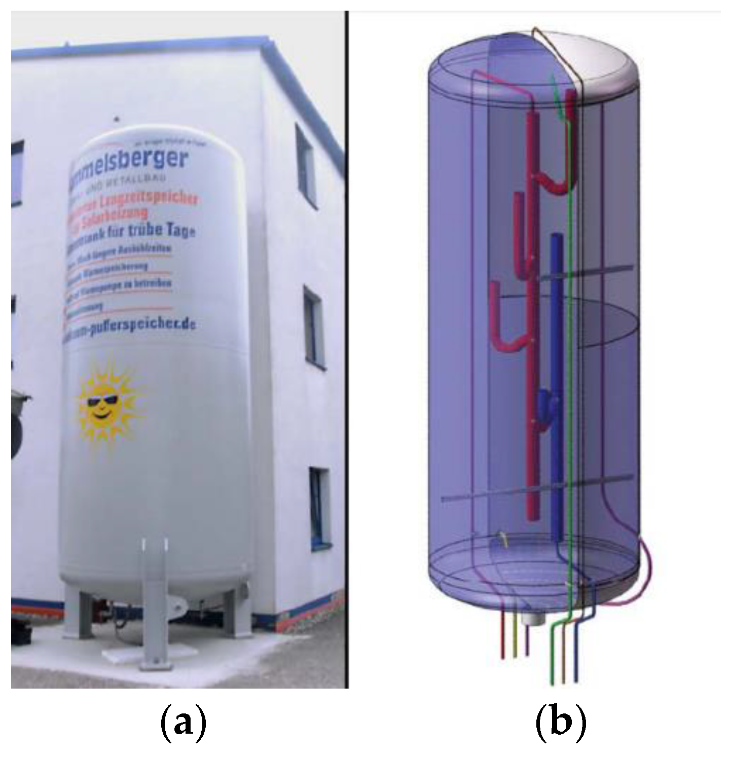
To use the seasonal storing of the solar heat energy for a single-family house, it is important to use a storage tank, with a low heat loss. One solution is to use a tank where the working principe is similar to that of thermos. The technique of the vacuum insulated tank with expanded perlite has been previously used for the storage of liquid gases. The vacuum insulated storage tank operational principle is similar. Using vacuum insulation, the thermal resistance is up to 10 times higher compared with conventional insulation materials [6]. The company Hummelsberger Stahl- und Metallbau built the vacuum isolated storage tank with a volume of 16.4 m3 in the year of 2010. The tank has a double-walled steel cylinder construction. The annular gap between the cylinders is filled with expanded perlite and is evacuated [7]. Such thermal insulation has been also investigated by the University of Stuttgart, where the different heat insulation materials are studied in a vacuum [7]. The results are similar to the parameters of the vacuum insulated tank insulation. The tank was put outside in winter and filled with 90 °C water. The measurements showed an average temperature loss of 0.23 K day−1 for a period of 11 weeks in winter [8]. It was found that the tank heat loss power is 1.98 W K−1 [9]. The heating system, with a similar 11 m3 vacuum storage tank, and the solar collector with an area of 55 m2, is in use in Germany. The entire heating system can be watched in real time [10]. The measurement data shows that the maximum temperature in the storage tank is achieved in May [10]. The share of direct heating is 55% [11]. Also, the climate in Germany is warmer than in Estonia. In Germany, a tank with vacuum panels insulation was also studied, of which the calculated U-value was 0.36 W m−2 K−1 [12]. The average U-value is high because of joints between the vacuum panels, which are thermal bridges.
It possible store solar energy using latent heat storage, where phase change materials are used [13]. These storage systems are more complex compared to conventional storage and the heat insulation that is also needed. Using chemical storage systems are not economically feasible [14]. Nonconventional storage methods are not investigated in this article.
The seasonal storage tank for the solar heat energy with vacuum insulation has not been previously investigated in Estonia or in the countries with a similar climate. Using solar energy for dwelling heating is not widely used in Estonia. The vacuum insulation storage technology is novel and allows for storing heat energy for a longer period for small buildings. In Estonia, there are no studies at all about the solar heat energy storage in residential heating systems. This article describes a simplified solution based on calculations of how and how much the vacuum insulated long-term solar heat energy storage tank in the solar heating system will increase the solar heat energy share for a single-family house using direct heating, in Estonian and other countries with a similar climate. Using solar energy to direct heating for dwelling can reduce the demand for other heat energy sources.
2. Materials and Methods
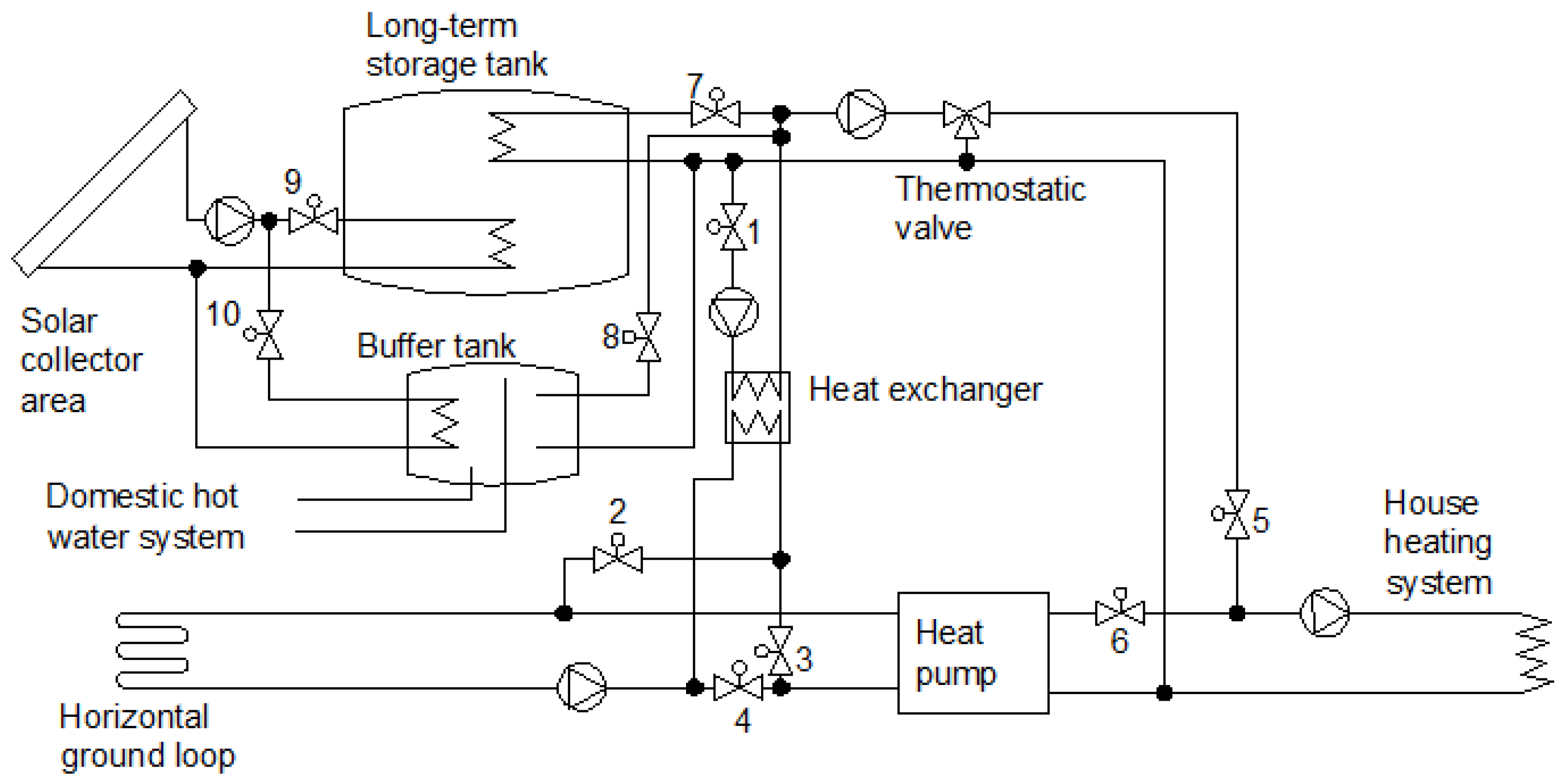
The calculations are based on the climate data of 2017 in Tartu, measured by the weather station. The weather station Vantage Pro+ is located on a building’s roof at 58°23′19″ N, 26°41′37″ E, at the height from ground 25 m. The measurements are taken by steps of 5 min. The yearly average temperature in this location is 5.8 °C and the solar potential 350 kWh m−2. The solar collectors are facing towards the south and the inclination angle is 60°. The heating system simplified circuit is shown in Figure 1. The system allows for the use of different heating modes, which are presented in Table 1. This paper describes only the solution of solar heat energy that is used for direct heating via a buffer or long-term heat storage tank. The tank stratification has not been taken into account. The calculations are based on the flow of energy.
Figure 1 shows also a heat pump part, which is not considered in detail in this paper. Ignoring the heat pump part does not affect the results of the calculations, because this article describes only the heat energy from the sun to the direct heating. In the article, only the heat energy is mentioned, which is needed to cover all of the house’s heat energy demand. This heat energy can be extracted using the heat pump. The amount of the additional heat energy is used to calculate the direct heating share.
Vacuum isolated heat storage tanks [15], solar collectors, and buffer tanks with the volume of 15 m3 have been selected for the calculations. A prototype of the vacuum insulated tank is showed in Figure 2.
The solar collectors Ensol ES2H/2.65 S are a flat plate type [16]. The main parameters of the heating system components and the house are described in Table 2. If the buffer tank temperature is greater than 45 °C, then the heat energy for domestic hot water will be also taken into account in the calculations. The daily hot water consumption is 150 kg and the temperature raise is by 50 K. The demand profile is not used. The calculations are made using steps of 5 min.
The single-family houses that have been used in the calculations are two-story and the shape is rectangular. To simplify the calculations, the external border area is summarized. The whole building is shown as one room and the occupancy pattern and lightning pattern are not used. The ventilation system is natural. The external border area, with a mean U-value 0.17 W m−2 K−1, was taken in for the calculations. The free heat power (3 W m−2) and dwelling mean U-value were based on the standards in Estonia.
The output power of the solar collector depends on the solar irradiation, collector area, and collector heat losses. The heat loss is related to the collector temperature and the ambient temperature. The higher difference between the solar collector and the ambient temperature causes a bigger heat loss. The solar collector temperature is related to the mean temperatures of the buffer tank and the long-term storage tank. The output power of the solar collector is calculated by the following formula [17]:
where is the collector output power, is the solar collector absorber area, is the zero lost efficiency, G is the solar irradiation, is the first order heat loss coefficient, is the second order heat loss coefficient, is the collector temperature, and is the ambient air temperature.
Firstly, the produced heat is directed into the buffer tank. If the temperature in the buffer tank raises over 36 °C, then the stored heat energy is used for the house’s direct heating. The house’s heat delivery system is floor heating, for which the supplied temperature is lower compared with the conventional heater [18]. If the temperature is greater than 45 °C, then the energy for the domestic hot water will be also taken from the buffer tank. If the temperature raises over 60 °C, then the produced heat energy will be directed in to the long-term storage tank. If the long-term storage tank temperature rises over 100 °C, then the heat energy is moved in to the heat pump ground loop. In autumn, when the solar irradiation is not enough for the buffer tank temperature to raise over 36 °C, the heat energy from the long-term tank is used for the house heating. The following formulas are the basis for calculating the buffer tank and the long-term tank temperature.
If < 36 °C, then the buffer tank temperature changes using the following formula:
where is the buffer tank temperature, is the buffer tank initial temperature, is the solar heat energy, is the buffer tank heat energy loss, is the water mass, and is the water specific heat capacity.
If > 36 °C, then the buffer tank temperature changes using the following formula:
where is the heat energy consumption of the house.
If > 45 °C then the buffer tank temperature changes, using the following formula:
where is the heat energy for the domestic hot water heating.
If > 60 °C and < 36 °C, then the storage tank temperature changes, using the following formula:
where is the storage tank temperature, is the storage tank initial temperature; is the storage tank heat energy loss, and is the storage tank water mass.
If <60 °C and >36 °C, then the storage tank temperature changes, using the following formula:
The heat capacity of the water is 0.001164 kW·h kg−1.
The efficiency of the direct heating system depends the stored heat energy and system losses, as follows:
where is the system efficiency, is the energy for direct heating, and is the energy to heat the pump ground loop.
The U-values that are used in this article are calculated using insulation thickness and insulation thermal resistance.
3. Results and Discussion
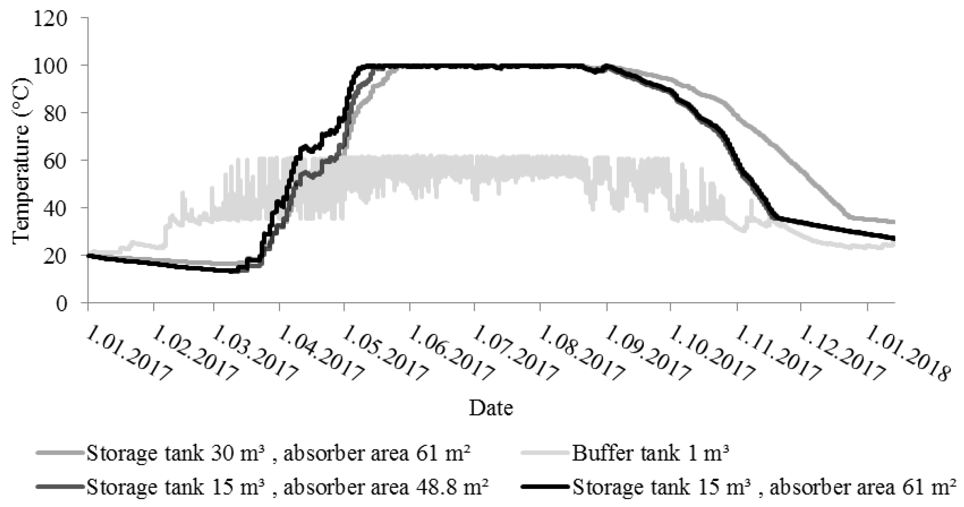
The buffer tank and the long-term storage tank temperature changes are shown on Figure 3.
The absorber area, buffer tank, and storage tank volumes are selected experimentally by trying out different parameters (solar collector absorber area, vacuum insulated tank volume, and direct heating share). It was important that the direct heating share of the house’s heat energy demand is over 40% and that the system efficiency is over 50%. The temperature of the buffer tank in all three of the analyzed conditions gave similar results, therefore, it is showed in one condition. The temperature change for the long-term tank depends on the area of the solar collectors and the tank volume. The tank, with a larger volume allows for storing more heat energy and to use it for a longer period. The time for heating up the long-term storage tank depends on the solar collector area. The maximum temperature of the long-term tank is achieved in May and the heating up time difference with different collector areas is small. The produced heat energy in the summertime is mostly used by heating the domestic hot water and by heating up the ground around the heat pump ground loop. The end of the direct heating for the house is visible in Figure 3, in the place where the long-term tank temperature drops under 36 °C.
In Figure 3, during the time between January and March, the vacuum insulated tank temperature drops, which is caused by heat loss from the tank. The tank’s initial temperature is taken as 20 °C. In Figure 3, the tank temperature in January 2018 shows that the tank temperature in all three of the different volumes is higher than 20 °C, which should be a direct rise in the heating share.
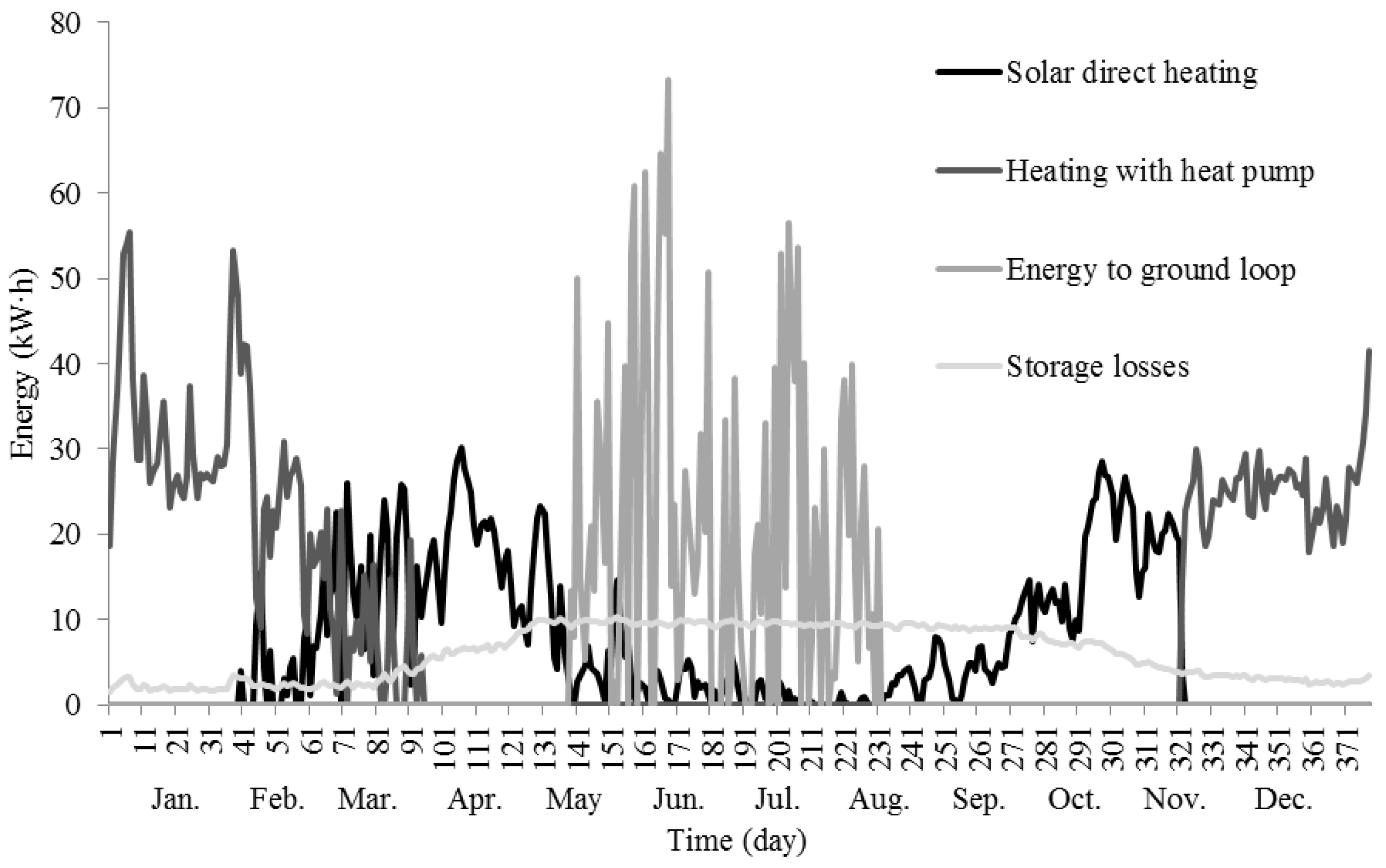
The heat energy balance for the year of 2017, with the solar collector absorber area of 48.4 m2 and the long-term storage tank with the volume of 15 m3, are shown in Figure 4. Between the end of November and the beginning of April, the heat pump is used for the house heating. The rest of the time the heat pump is standing and the heat energy for heating the house and the domestic hot water is collected from the sun. The heat loss of the buffer tank and the long-term storage tank will not exceed 10 kW·h a day. Most of this heat loss is the heat loss of the buffer tank. The data from Figure 4 is summarized and shown in Table 3.
If also considering the heat energy that is directed into the ground as a heat loss, then the direct heating system efficiency is 51%. The direct heating share of the house’s yearly heat energy demand is 41%. The heating system efficiency for different parts is presented in Table 4.
Comparing the results to the similar system, which located in Germany, one can be say that the solar energy share for the dwelling heating in Germany is greater (41% vs. 55%), because the climate there is also warmer [11]. The volume of the tank is 11m3.
The overproduced heat energy, which is directed into the heat pump ground loop in summertime, should raise the temperature of the ground. A higher ground temperature should reduce length of the heat pump ground loop and increase the heat pump inlet temperature in the heating season when stored solar energy is over. Increasing the inlet temperature of the heat pump will increase the coefficient of performance (COP). The COP is how many times the energy can heat the pump to move the heat pump inlet energy. This is only an assumption and will need a further investigation.
4. Conclusions
This paper presents a simplified method for increasing the share of solar direct heating for a single-family house. The calculations show the use of a vacuum insulated tank for seasonal heat energy storage, which makes it possible to increase the solar heat energy share for the direct heating. The results show that the maximum temperature of the long-term storage tank (15 m3) is achieved in May. The share of the solar energy for direct heating will increase to a level of 41%. This can be further increased by using a larger long-term storage tank. The additional heat demand is 59%. A heat pump is used for the house’s heating from the beginning of December to the end of March. The solar direct heating and the heating with the heat pump are used together in March. The main conclusions are as follows:
- Heating system efficiency is 51%. This can be improved to better utilize the energy, which is directed in to the ground;
- Heating system storage losses are 27%; and
- Share of direct heating is 41%, if using a 15 m3 storage tank.
Author Contributions
Study conception and design: J.K., A.A. (Andres Annuk), A.A. (Alo Allik), E.K.; Acquisition of data: J.K.; Analysis and interpretation of data: J.K., A.A. (Andres Annuk); Drafting of manuscript: J.K., A.A. (Andres Annuk), A.A. (Alo Allik), E.K.; Critical revision: J.K., A.A. (Andres Annuk), A.A. (Alo Allik), E.K.
Funding
This research was funded by the Estonian Centre of Excellence in Zero Energy and Resource Efficient Smart Buildings and Districts, ZEBE, grant 2014-2020.4.01.15-0016, funded by the European Regional Development Fund.
Acknowledgments
This research was supported by the Estonian Centre of Excellence in Zero Energy and Resource Efficient Smart Buildings and Districts, ZEBE, grant 2014-2020.4.01.15-0016, funded by the European Regional Development Fund.
Conflicts of Interest
The authors declare no conflict of interest.
References
- European Commission. 2030 Energy Strategy. Available online: https://ec.europa.eu/energy/en/topics/energy-strategy-and-energy-union/2030-energy-strategy (accessed on 20 December 2017).
- Directive 2010/31/EU of the European Parliament and of the Council of 19 May 2010 on the Energy Performance of Buildings. Available online: https://eur-lex.europa.eu/LexUriServ/LexUriServ.do?uri=OJ:L:2010:153:0013:0035:EN:PDF (accessed on 3 July 2018).
- Xu, J.; Wang, R.Z.; Li, Y. A review of available technologies for seasonal thermal energy storage. Sol. Energy 2013, 103, 610–638. [Google Scholar] [CrossRef]
- Meissner, R.; Abrecht, S. Sense and Nonsense of Solar Thermal Storage. Available online: http://ritter-xl-solar.com/uploads/media/Sense_and_Nonsense_of_solar_thermal_storage.pdf (accessed on 22 March 2018).
- Kny, M.; Urban, M. Solar System with Long-term Heat Storage—Analysis and Optimisation. In Proceedings of the 11th REHVA World Congress & 8th International Conference on IAQVEC—Energy Efficient, Smart and Healthy Buildings, Prague, Czech Republic, 16–19 June 2013. [Google Scholar]
- Fricke, J.; Schwab, H.; Heinemann, U. Vacuum Insulation Panels—Exciting Thermal Properties and Most Challenging Applications. Int. J. Thermophys. 2006, 27, 1123. [Google Scholar] [CrossRef]
- Lang, S.; Gerschitzka, M.; Bauer, D.; Drück, H. Thermal conductivity of vacuum insulation materials for thermal energy stores in solar thermal systems. Energy Procedia 2016, 91, 172–181. [Google Scholar] [CrossRef]
- Beikircher, T.; Buttinger, F.; Demharter, M. Super-insulated long-term hot water storage. In Proceedings of the ISES Solar World Congress, Kassel, Germany, 28 August–2 September 2011. [Google Scholar]
- Epp, B. Vacuum Super Insulation Reduces Heat Losses at Long-Term Storage. Global Solar Thermal Energy Council, 2013. Available online: http://www.solarthermalworld.org/content/germany-vacuum-super-insulation-reduces-heat-losses-long-term-storage (accessed on 20 December 2017).
- Visualisierung-WebControl. Available online: http://vakuumpuffer.dyndns.org/heizung.php (accessed on 20 December 2017).
- Vacuum Storage. Available online: http://vakuum-pufferspeicher.de/installationsbeispiele.html (accessed on 20 December 2017).
- Benjamin, B.; Hofbecka, K. First Experience in Vacuum Insulated Hot Water Storage with 100 m3. Energy Procedia 2014, 57, 2390–2398. [Google Scholar] [CrossRef]
- Sharma, A.; Tyagi, V.V.; Chen, C.R.; Buddhi, D. Review on thermal energy storage with phase change materials and applications. Renew. Sustain. Energy Rev. 2009, 13, 318–345. [Google Scholar] [CrossRef]
- Krese, G.; Koželj, R.; Butala, V.; Stritih, U. Thermochemical seasonal solar energy storage for heating and cooling of buildings. Energy Build. 2018, 164, 239–253. [Google Scholar] [CrossRef]
- Vacuum High Power. Available online: http://vacuum-storage.com/series-vacuum-high-power.html (accessed on 20 December 2017).
- Ensol. Technical Data of the Flat Solar Collectors. Available online: http://ensol.pl/new_ensol/wp-content/uploads/2016/10/EN-Technical-Data-ES2H265-072015.pdf (accessed on 20 December 2017).
- ESTIF. Objective Methodology for Simple Calculation of the Energy Delivery of (Small) Solar Thermal System. 2007. Available online: http://www.estif.org/fileadmin/estif/content/policies/downloads/Simple_Calculation.pdf (accessed on 20 December 2017).
- Sarbu, I.; Sebarchievici, C. A study of the performances of low-temperature heating systems. Energy Effic. 2015, 8, 609. [Google Scholar] [CrossRef]
Figure 1.
Simplified circuit of the heating system.

Figure 2.
Vacuum insulated prototype tank (a) and inner container sketch with pipelines (b) [8].
Figure 2.
Vacuum insulated prototype tank (a) and inner container sketch with pipelines (b) [8].

Figure 3.
The temperatures of the buffer and long-term storage tank with different settings.

Figure 4.
The daily energy of heating system components in the year of 2017.


Table 1.
The working modes of the heating system.
| Heating Mode | Open Valves | Closed Valves |
|---|---|---|
| Direct heating using buffer tank. | 5, 8 | 1, 2, 3, 4, 6, 7 |
| Direct heating using vacuum insulated tank. | 5, 7 | 1, 2, 3, 4, 6, 8 |
| Using residual heat from buffer tank to increase heat pump inlet temperature. | 1, 3, 6, 7 | 2, 4, 5, 8 |
| Heat pump is working and input energy delivered from ground loop. | 4, 6 | 1, 2, 3, 5, 7, 8 |
| Overproduced heat energy is stored in to the ground. | 1, 2, 7 | 3, 4, 5, 6, 8 |
Table 2.
The main parameters of components of the heating system.
| Description of System Component | Symbol | Value |
|---|---|---|
| Solar collector absorber area | Ac | 2.44 m2 |
| Solar collector zero lost coefficient | a0 | 0.824 |
| Solar collector linear loss coefficient | a1 | 2.905 W m−2 K−1 |
| Solar collector quadratic loss coefficient | a2 | 0.03 W m−2 K−1 |
| House average heat transmission coefficient | U | 0.17 W m−2 K−1 |
| House surface area | Ab | 434 m2 |
| House inside temperature | tin | 21 °C |
| Free heating power | Pf | 3 W m−2 |
| House floor area | Ahouse | 160 m2 |
| Storage tank volume | Vtank | 15,000 kg |
| Storage tank surface area | Atank | 52.4 m2 |
| Storage tank heat transmission coefficient | Utank | 0.07 W m−2 K−1 |
| Storage tank maximum operating temperature | top | 110 °C |
| Buffer tank volume | Vbuf | 1000 kg |
| Buffer tank surface area | Abuf | 6 m2 |
| Buffer tank heat transmission coefficient | Ubuf | 0.4 W m−2 K−1 |
| Daily hot water energy consumption | Qwater | 10.5 kW·h |
Table 3.
Heat energy balance.
| Description | Heat Energy (kW·h) |
|---|---|
| House yearly heat energy demand | 6023 |
| Produced heat energy from sun | 8560 |
| Solar heat energy for direct heating | 2474 |
| Additional heat energy demand (ground source heat pump) | 3549 |
| Energy to heat pump ground loop | 1903 |
| Buffer tank and storage tank losses | 2312 |
| Storage losses | 4215 |
Table 4.
Heating system efficiency.
| Description | Efficiency |
|---|---|
| Direct heating system efficiency | 51% |
| Solar irradiation to collected heat energy efficiency | 20% |
| Direct heating | 41% |
| Additional energy demand | 59% |
| Buffer tank losses | 6% |
| Vacuum insulated tank losses | 21% |
| Heat energy to ground | 22% |
© 2018 by the authors. Licensee MDPI, Basel, Switzerland. This article is an open access article distributed under the terms and conditions of the Creative Commons Attribution (CC BY) license (http://creativecommons.org/licenses/by/4.0/).
Share and Cite
MDPI and ACS Style
Kalder, J.; Annuk, A.; Allik, A.; Kokin, E. Increasing Solar Energy Usage for Dwelling Heating, Using Solar Collectors and Medium Sized Vacuum Insulated Storage Tank. Energies 2018, 11, 1832. https://doi.org/10.3390/en11071832
AMA Style
Kalder J, Annuk A, Allik A, Kokin E. Increasing Solar Energy Usage for Dwelling Heating, Using Solar Collectors and Medium Sized Vacuum Insulated Storage Tank. Energies. 2018; 11(7):1832. https://doi.org/10.3390/en11071832
Chicago/Turabian StyleKalder, Janar, Andres Annuk, Alo Allik, and Eugen Kokin. 2018. "Increasing Solar Energy Usage for Dwelling Heating, Using Solar Collectors and Medium Sized Vacuum Insulated Storage Tank" Energies 11, no. 7: 1832. https://doi.org/10.3390/en11071832
Note that from the first issue of 2016, this journal uses article numbers instead of page numbers. See further details here.