Article

Design, Analysis and Model Predictive Control of an Axial Field Switched-Flux Permanent Magnet Machine for Electric Vehicle/Hybrid Electric Vehicle Applications

1
School of Automation and Information Engineering, Xi’an University of Technology, Xi’an 710048, China
2
Engineering Research Center for Motion Control of Ministry of Education, Southeast University, Nanjing 210096, China
*
Author to whom correspondence should be addressed.
Energies 2018, 11(7), 1859; https://doi.org/10.3390/en11071859
Submission received: 8 June 2018 / Revised: 13 July 2018 / Accepted: 15 July 2018 / Published: 16 July 2018

Abstract

:
In this paper, an axial field switched-flux permanent magnet (AFSFPM) machine with stator-PM, which has a high power/torque density and efficiency feature as well as shorter axial length, is designed, analyzed and controlled. The topology, operating principle and design procedure of the AFSFPM machine are labored and discussed. The electromagnetic performance, including the flux linkage, back-EMF, cogging torque, winding inductance and field-control capability, are studied based on 3-D finite-element analysis (FEA). In order to investigate the operating performance of the machine in the whole speed range, a continuous-control-set model predictive control (MPC) method for the AFSFPM machine is proposed. Based on the stage control targets, the maximum torque per ampere (MTPA) and maximum output power flux-weakening strategies are presented in constant torque and constant power regions, respectively. Finally, a prototype of AFSFPM machine has been manufactured and experimentally evaluated and the results show that the MTPA strategy increases the load capability and the flux-weakening strategy broadens the constant power operation range. Moreover, the anti-load-disturbance capacity and dynamic response performance are improved under the MPC method. As a result, the proposed AFSFPM machine drive system is excellent alternative for electrical vehicles (EVs) or hybrid EVs (HEVs).

1. Introduction

Recently, the axial flux permanent magnet (AFPM) machines have attracted a huge amount of attention from the researchers and industry because of some magnetic and geometric structure merits compared to the radial PM machine, which are very interesting for the electrical vehicles (EVs) and wind power applications [1,2,3,4,5,6,7]. The switched-flux permanent magnet (SFPM) machine with stator-PM, are being considered and under extensive investigation due to simple structure, robust rotor, high power/torque density, as well as sinusoidal electromotive force (EMF) [8,9,10,11,12,13,14,15]. Axial field switched-flux permanent magnet (AFSFPM) machine combines the characteristics of the AFPM and SFPM machine, which exhibits some merits of shorter axial length, robust rotor structure, high power/torque density and efficiency, convenient heat-dissipation and flexible control. A 12/10 dual-rotor AFSFPM machine was presented for wind power generation in [16]. The influences of the rotor pole width and stator slot chamfer on the back-EMF and cogging torque were investigated. Static characteristics of a dual-stator AFSFPM motor with three stator structures had been investigated in [17] and the results shown the motor with parallel PM and slot topology has larger torque, lower cogging torque and more sinusoidal back-EMF. The fault-tolerant operating capability of AFSFPM machine with ‘E-shaped’ stator tooth was improved and the wide speed-regulation range was achieved in [18,19]. A novel SFPM machine with dual-rotor, axial field, fault-tolerant structure for the direct-drive applications was proposed in [20]. The research results indicated, compared with the conventional FSPM machine, the proposed machine exhibits higher power/torque density and lower cogging torque. Several 6-slot/4-pole axial switched-flux machine topologies for EVs and hybrid electric vehicles (HEVs) were investigated in [21] and the even harmonics of the flux-linkage in the proposed 6-slot/4-pole machines were eliminated efficiently. A new topology of single-phase switched-flux AFPM motor was presented in [22], for the enhancement of the self-starting torque capability and unidirectional rotation, the rotor pole was tapered. A novel AFSFPM machine with hybrid excitation structure was proposed in [23], the result demonstrated the load-capability was improved and the speed-regulation range was broadened. 3-D finite-element method is frequently used to analyze the AFPM machine and the optimization design is very necessary to improve the machine performance. Optimization design of electrical machine is considered to be computationally demanding and costly due to the 3-D FEA process involved. To reduce the computational time and the cost as well, the optimization algorithms, such as genetic algorithm [24], particle swarm optimization algorithm [25] and difference evolution algorithm [26], have been presented. Recently, many alternatives such as surrogate-assisted model [27] which emulates the behavior of the real machine performance, is less accurate but much faster, have also been emerged to improve the optimization efficiency of electrical machines, especially for those machines with 3-D flux topologies which requires 3-D FEM, such as the transverse and axial flux as well as claw pole machine. The characteristics of several optimization design models, methods and strategies for electrical machine are summarized and analyzed in [28].
The model predictive control (MPC) method exhibits a lot of merits including fast torque response, strong robustness and high dynamic performance. Three predictive current control schemes for permanent magnet synchronous motor (PMSM) control system were presented and compared based on simulation and experimental research in [29]. A novel speed finite-control-set MPC algorithm for a PMSM by a matrix converter, which replace the classical cascaded control scheme, was proposed in [30]. An effective method to simplify the finite control set-MPC and to reduce the calculation efforts in matrix converter-fed PMSM drive was presented in [31] and the good performance was achieved. A modified predictive torque control scheme for a PMSM to reduce the torque ripple at the presence of parametric uncertainly by improving the prediction accurateness was presented in [32]. A common MPC for PMSM drives considering single-phase open-circuit fault was proposed in [33].
The aim of this paper is to design, analysis and control as well as access of a three-phase 12-stator-slot (s)/10-rotor-pole (p) AFSFPM machine, as depicted in Figure 1. Different from our previous works [34,35], which focused on machine design for different applications such as EVs or direct-drive wind power system, the contributions of this paper are to investigate the operating performance of AFSFPM machine drive system in the entire speed operating region with emphasis on control strategies, which can offer effective torque and speed control. In this paper, a continuous-control-set model predictive control (CCS-MPC) method for the AFSFPM machine drive system is presented to improve the dynamic response and anti-load-disturbance capacity of the drive system. The electromagnetic characteristics of the AFSFPM machine, such as the flux linkage, back-EMF, cogging torque and the winding inductance, are researched based on the 3-D finite-element analysis (FEA). Eventually, the simulation and experimental study are executed to demonstrate the effectiveness of the proposed control method and the operating performance of the AFSFPM machine.

2. Machine Design

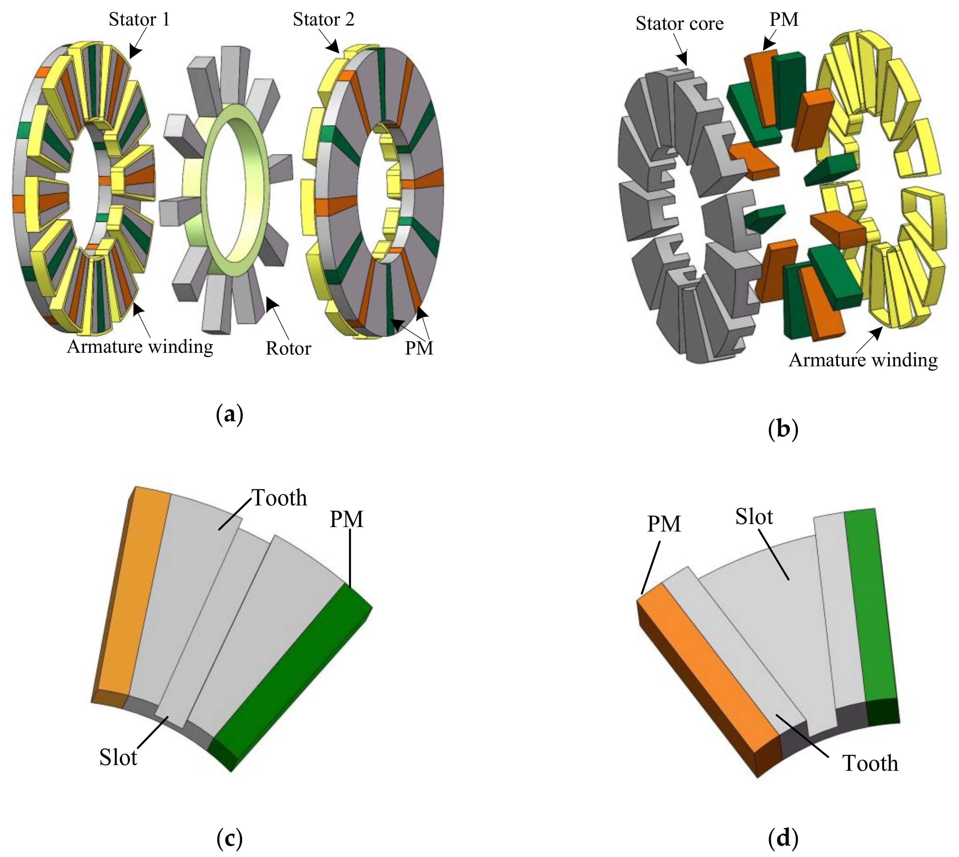
2.1. Target Machine Configuration

Figure 1a describes a three-phase 12-stator-slot/10-rotor-pole AFSFPM machine consisted of double stators and single rotor. As seen in Figure 1b, the salient pole stator includes 12 ‘U’-type core, 12 PMs and concentrated armature windings. The PMs with alternant magnetizing are embedded between the two adjacent ‘U’ type cores and the armature windings are coiled radially the module composed of two adjacent ‘U’ type cores and embedded PM. Two different stator structures of parallel PM parallel slot (PPPS) and parallel PM parallel tooth (PPPT) are investigated in this paper, as depicted in Figure 1c,d. The structure of two outer stators is same exactly and there are neither PMs nor windings in the rotor, which improves the robustness of rotor. PMs of the opposite stator have reversed magnetizing director. The PM flux and armature-reaction flux together forms air-gap flux along the axial direction and the windings of stator 1 and stator 2 are in series or parallel each other.

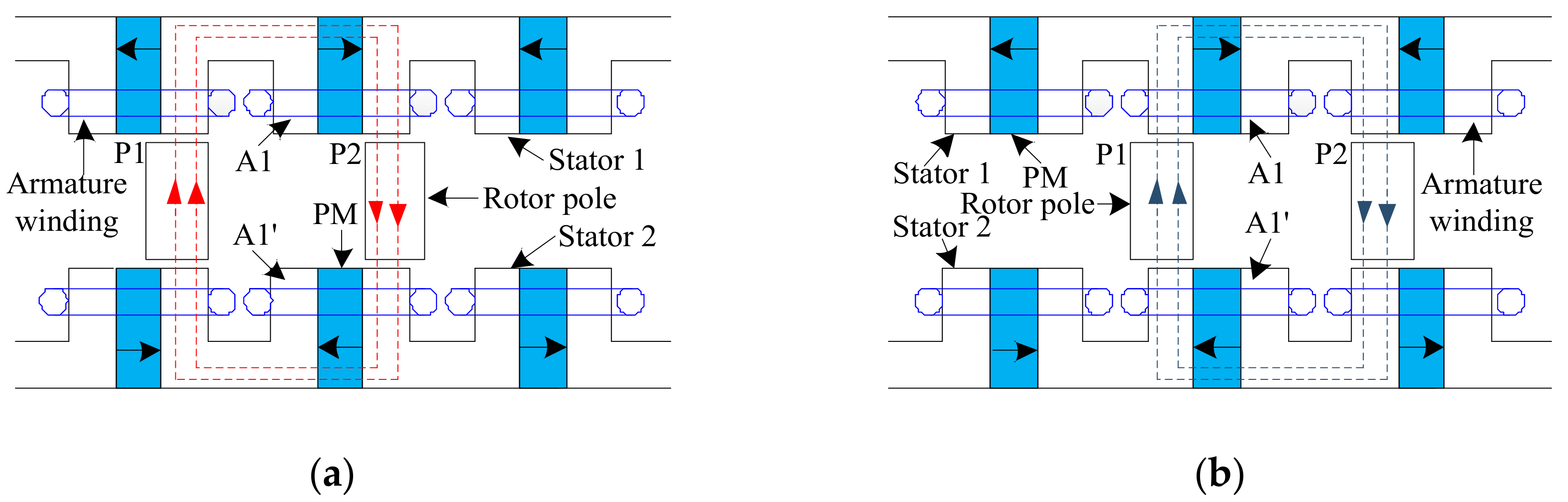
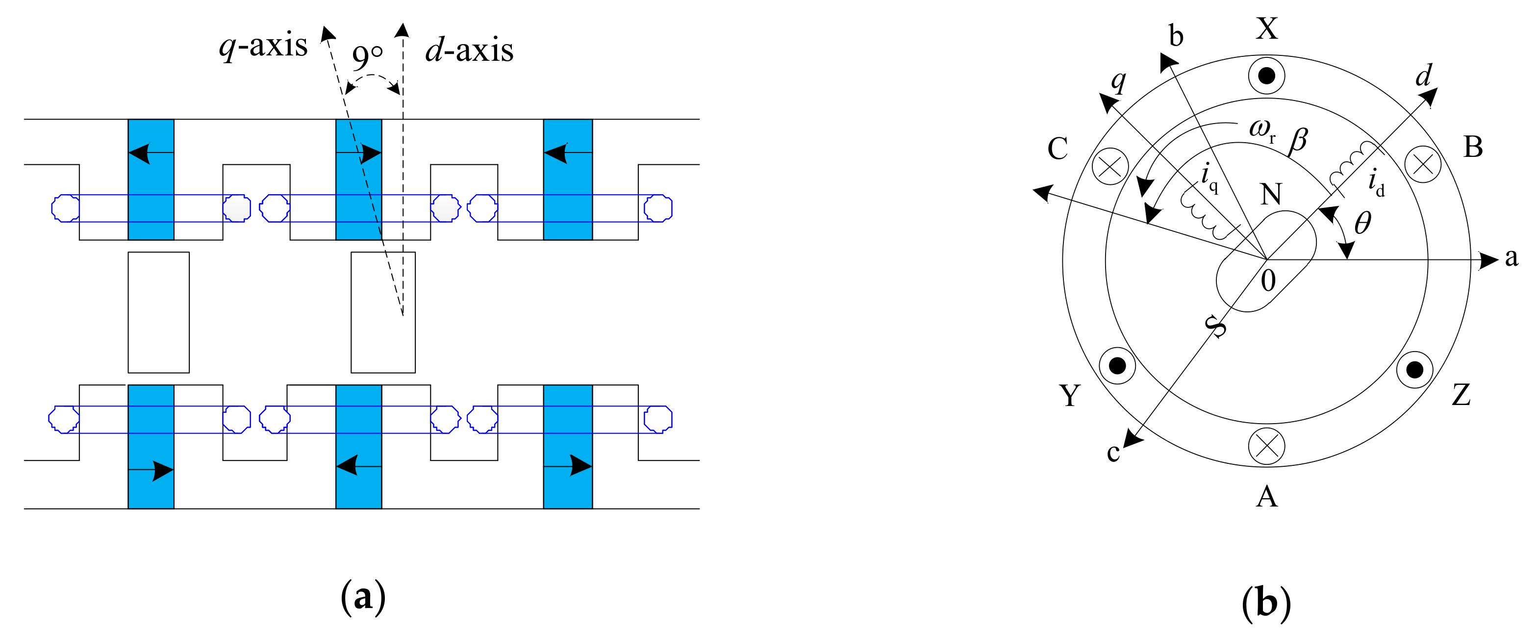
2.2. Operating Principle
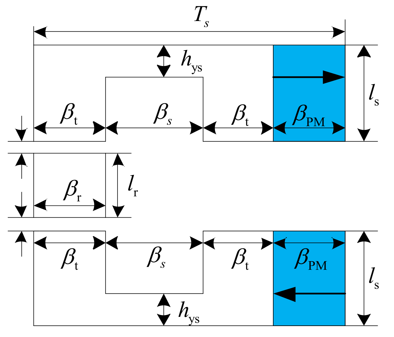
Figure 2 describes the switched-flux operating principles of the three-phase 12s/10p AFSFPM machine shown in Figure 1 based on the 2-D plane. When the rotor rotates from the position a in Figure 2a to position b in Figure 2b, the polarity of PM flux-linkage linking the armature windings A1 and A1’ are reversed at two different position, respectively. For example, from Figure 2a to Figure 2b, the PM flux-linkage linked by the armature coils A1 diminished from maximum to minimum. Consequently, the polarity and amplitude of the PM flux-linkage linking the armature windings A1 and A1’ alter periodically with the changing continuously rotor position and the switched-flux is realized.

2.3. Key Dimensions

The electromagnetic power of AFSFPM machine is written as
P e = m T 0 T e ( t ) i ( t ) d t = m T 0 T E m sin ( 2 π T t ) I m sin ( 2 π T t ) d t = m 2 E m I m
where Pe is the electromagnetic power. m is the phase numbers. T is the electrical period. Em is the amplitude of phase EMF. Im is the amplitude of phase current.
The EMF em at no-load can be indicated as
e m = N c o i l d φ d t = N c o i l d φ d θ r d θ r d t = N c o i l d φ d θ r ω r = N c o i l n π 30 d φ d θ r
where Ncoil is the number of turn per phase, ωr is the angular velocity, θr is the rotor position angle and φ is the flux, which can be defined as
φ = ϕ m cos ( P r θ r ) = k d k F B g max c s π ( D s o 2 D s i 2 ) 4 P s cos ( P r θ r )  
where ϕm is the amplitude of the flux, Pr is the number of rotor poles, Ps is the number of stator slot, kd is the leakage flux factor, kF is the factor of air-gap flux density, Bgmax is the peak value of air-gap flux density, cs is the area ratio of stator tooth and tooth-slot unit, Dsi is the stator inner diameter, Dso is the stator outer diameter.
Substituting (3) into (2), the EMF can be rewritten as
e m = N c o i l n π 30 d φ d θ r = P r P s × π 2 N c o i l k d k F c s n B g max ( D s o 2 D s i 2 ) 120 sin ( P r θ r ) = E m sin ( P r θ r )  
where
E m = P r P s × π 2 N c o i l k d k F c s n B g max ( D s o 2 D s i 2 ) 120  
The amplitude of phase current can be expressed as
I m = 2 I r m s = 2 A s π D s i 2 m N c o i l
where Irms is the root-mean-square (RMS) phase current value and As is the maximum current density.
Substituting (6) and (5) into (1), the electromagnetic power can be expressed as
P e = m 2 E m I m = 2 π 3 240 P r P s k d k F c s n A s B g max D s i ( D s o 2 D s i 2 ) = 2 π 3 240 P r P s k d k F c s n A s B g max λ ( 1 λ 2 ) D s o 3  
where λ is the diameter ratio of the machine, which is defined as
λ = D s i D s o
By combining the above equations, the output power can be expressed as
P o u t = 2 π 3 240 P r P s η k d k F c s n A s B g max λ ( 1 λ 2 ) D s o 3  
where η is the efficiency at the motor shaft.
According to the Equation (9), the stator outer diameters can be gotten as
D s o = 240 P o u t P s 2 π 3 P r η k d k F c s n A s B g max λ ( 1 λ 2 ) 3
Based on the above-mentioned analysis, when the output power and speed are given, the main dimensions of the AFSFPM machine can be obtained.
The key geometrical parameters in the AFSFPM machine are depicted in Figure 3. All angles are considered to be in the inner diameter of the stator. According to Equation (10), a three-phase 12s/10p AFSFPM machine is designed and these key original design parameters for a specification are tabulated in Table 1.
In order to gain the maximum output power as well as minimum cogging torque, an optimal design as listed in Table 1 is obtained for this AFSFPM machine.

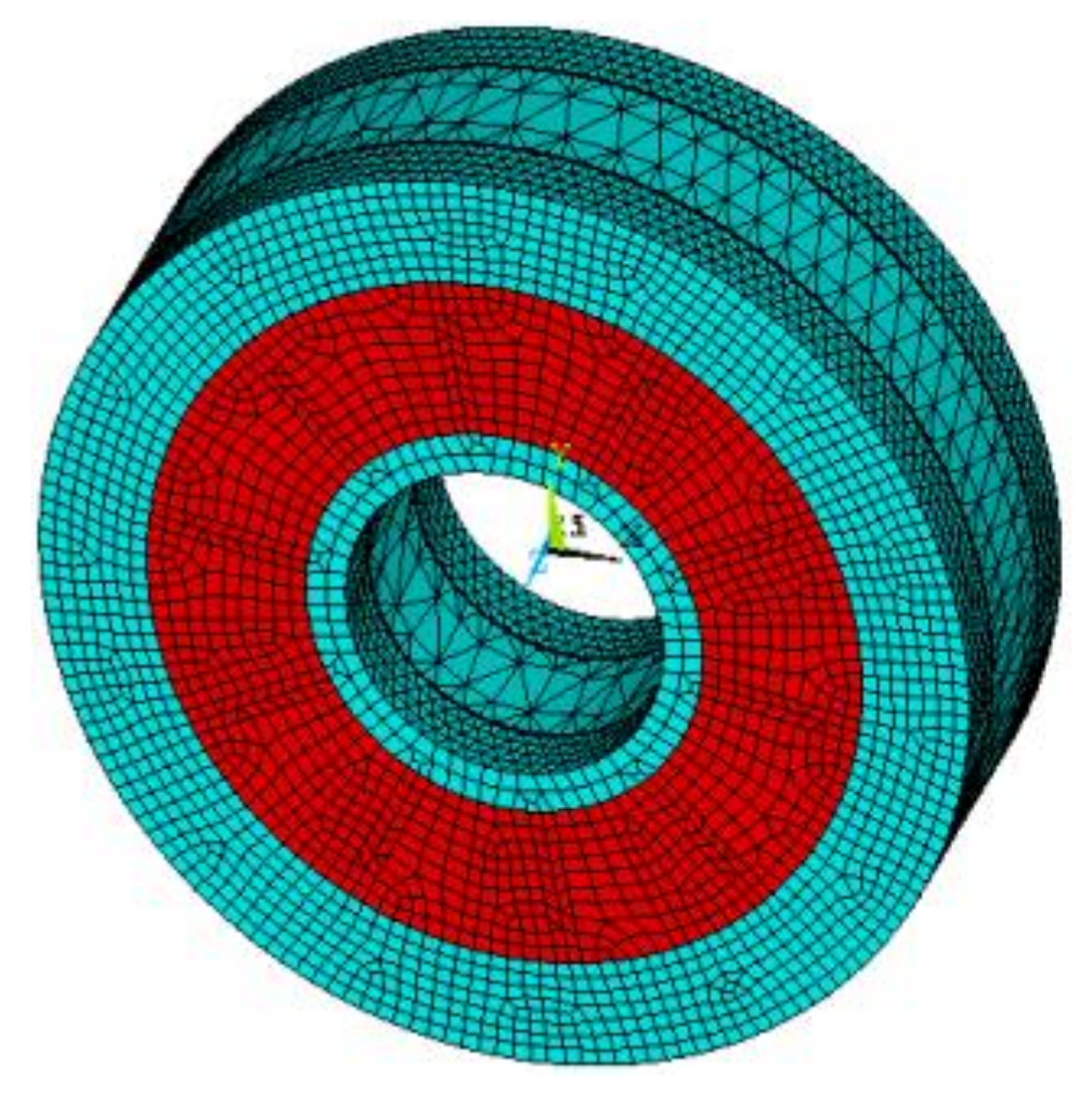
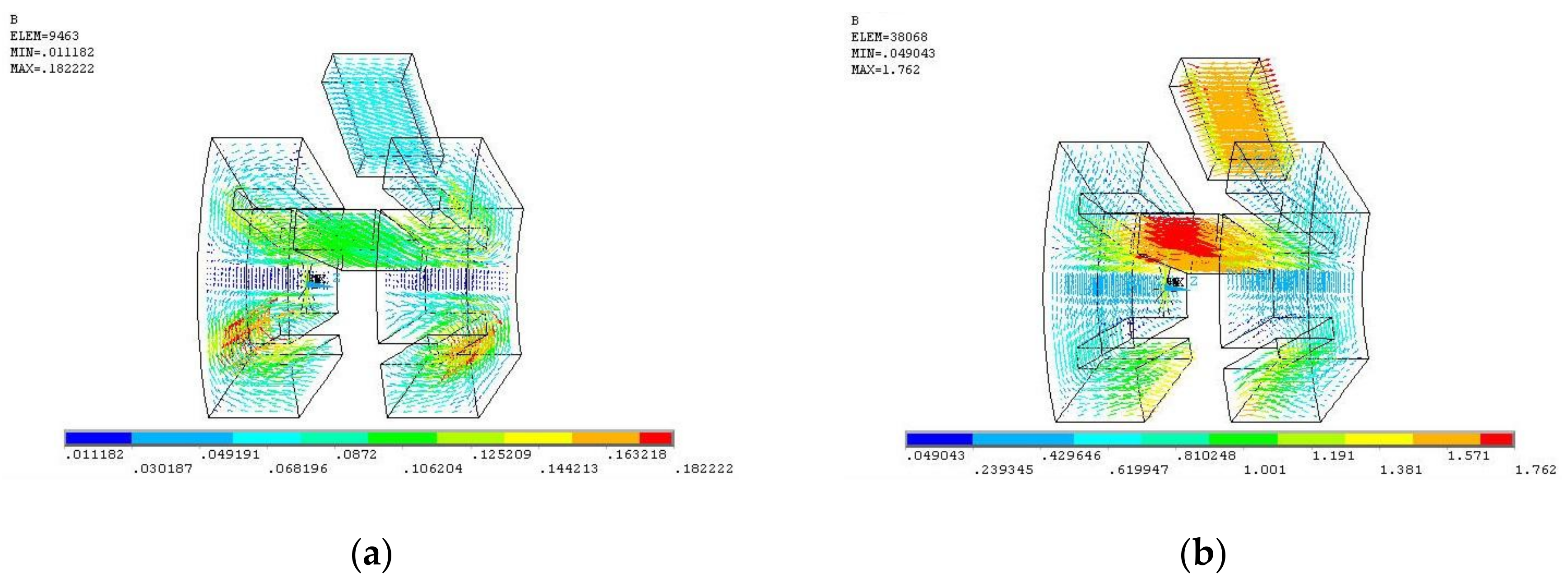
3. Electromagnetic Performance Analysis

Due to inherent 3-D magnetic flux path of the AFSFPM machine, 3-D FE method is used to calculate accurately the flux density distribution, the flux linkage and the EMF characteristics and to evaluate the performance of the AFSFPM machine. The 3-D FEA model of the AFSFPM machine, whose geometric parameters have been optimized based on the above-mentioned analysis, has been built as shown in Figure 4. Considering the influence of leakage flux on the accuracy of the finite element calculation results, the virtual air cover, which simulates the air environment, is added outside the FEA model.

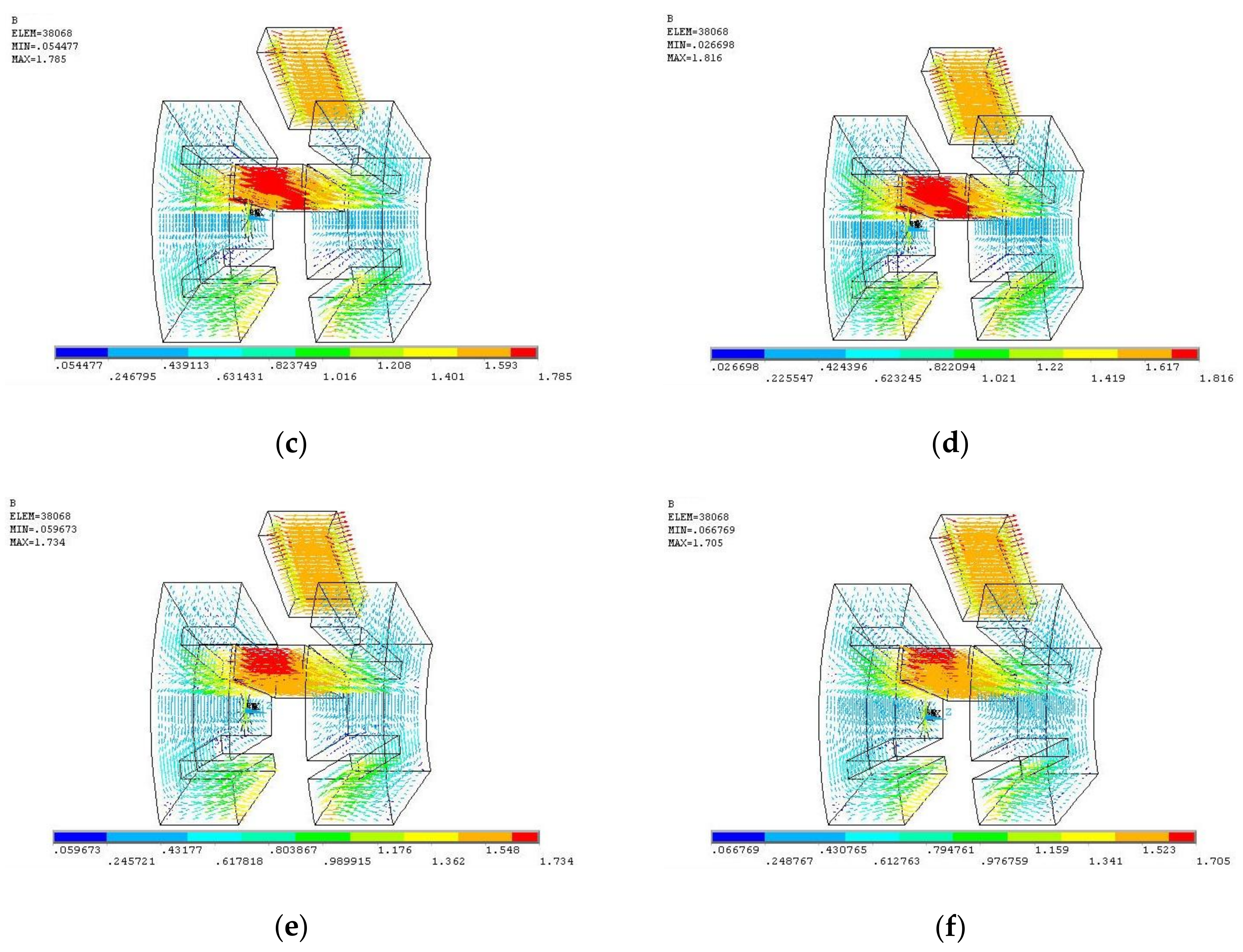
3.1. Magnetic Field Distribution

Based on the axial field switched-flux operating principle, there are four classical rotor positions for the AFSFPM machine in one electrical period, that is, rotor position angle θr is 0°, 9°, 18° and 27°. Considering the effect of the PM and armature reaction-field, the magnetic field characteristic of the AFSFPM machine is investigated. The open-circuit PM and the armature reaction-field distributions with PPPS structure, under the condition of the only PM and only armature current respectively at θr = 0°, are compared as depicted in Figure 5. It demonstrates that the path of the PM and armature reaction flux are in parallel.
As seen in Figure 5a,b, the armature reaction flux density peak, under the forward armature current density of 3.50 A, only is about 0.182 T, which is much less than the peak of the PM flux density of 1.762 T at no-load with armature current density of 0 A. It is consistent with theoretical analysis. When the forward armature current density of 1.75 A and 3.50 A are injected to the armature windings respectively, the flux density distributions under combined effect of PM field and armature reaction-field are depicted in Figure 5c,d. As the increasing of the armature current, the air-gap flux density peak gets larger and the magnetic circuit is gradually saturated. When the reverse armature current density of 1.75 A and 3.50 A are injected into the armature windings respectively, the air-gap flux density distributions are described in Figure 5e,f. Compared to the flux-weakening condition with the reverse armature current density, the air-gap flux density peak is larger under the flux-strengthening condition with the forward armature current density at any rotor position. The influence of the forward or reverse armature current density condition on the air-gap flux density is also relevant with the rotor position in a whole period and which is same as the traditional PMSM.

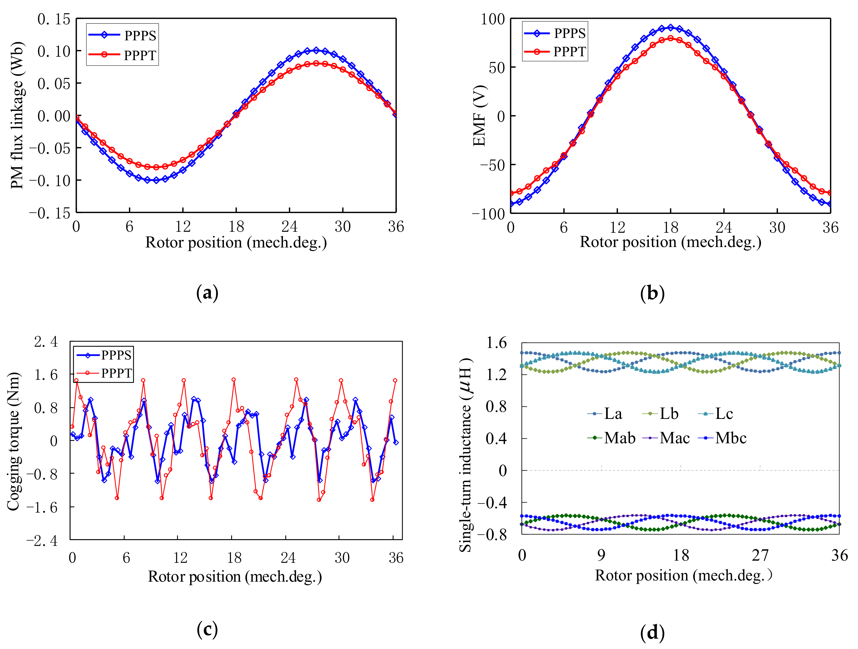
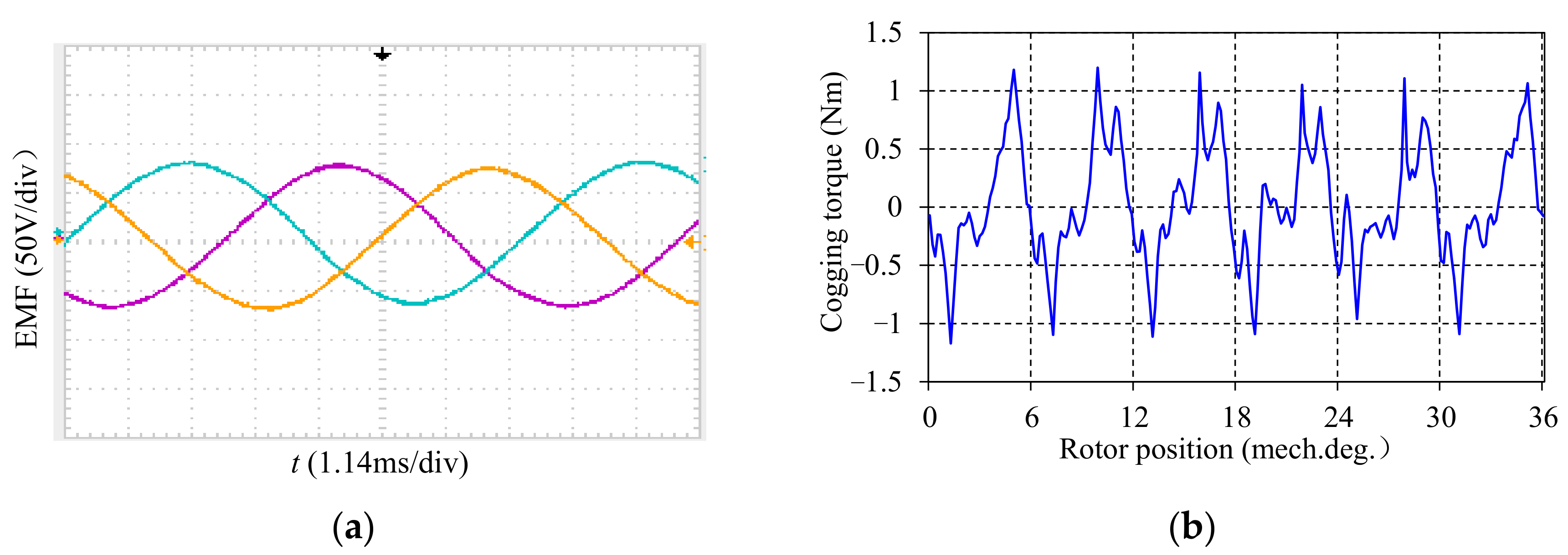
3.2. PM Flux-Linkage, Back-EMF, Inductance and Cogging Torque

The concentrated armature windings in stator 1 and stator 2 are in series. As depicted in Figure 6, the PM flux linkage, EMF, cogging torque and mutual-inductance and the self-inductance of PPPS and PPPT structures are calculated by 3-D FE method. Figure 6a describes the comparison results of the single-phase PM flux linkage of PPPS and PPPT structure. Figure 6b shows the comparison waveform of the single-phase EMF of PPPS and PPPT structure at rated speed of 750 r/min under no-load. The cogging torque waveforms of PPPS and PPPT structure are depicted in Figure 6c.
As seen from Figure 6a, the single-phase PM flux linkages of the machines with the PPPS and PPPT structures present sinusoidal distribution. The PM flux linkage amplitude of PPPT structure is 0.08 Wb, which is lower than that of the PPPS structure due to the different stator structure. The EMF waveform of PPPT structure is non-sinusoidal, which is different from the sinusoidal EMF of PPPS structure. The EMF amplitude of PPPT structure is 80 V, which is lower than PPPS structure, as depicted in Figure 6b. The aforementioned calculation results are accord with the theoretical analysis. As shown in Figure 6d, the cogging torque peak value of PPPS structure is about 0.95 N·m that 12.8% of the rating torque, while PPPT structure is about 1.42 N·m that 19.1% of the rating torque. Due to the flux-focusing effect caused by the axial doubly salient structure and very high flux density, the cogging torque of the AFSFPM machine is slightly high relative to the conventional PMSMs. However, the cogging torque can be reduced based on the optimization method in view of design and control. Figure 6d demonstrates the variation of self-inductance and mutual inductance of the armature winding of PPPS structure with the rotor position. The inductances are sinusoidal distribution and the mutual inductance is the half of self-inductance because of the switched-flux operating principle.
Based on the above-mentioned analysis, the AFSFPM machine with PPPS structure can be operated well in brushless AC mode. Hence, this paper chooses the machine with structure of PPPS as the object of further study.

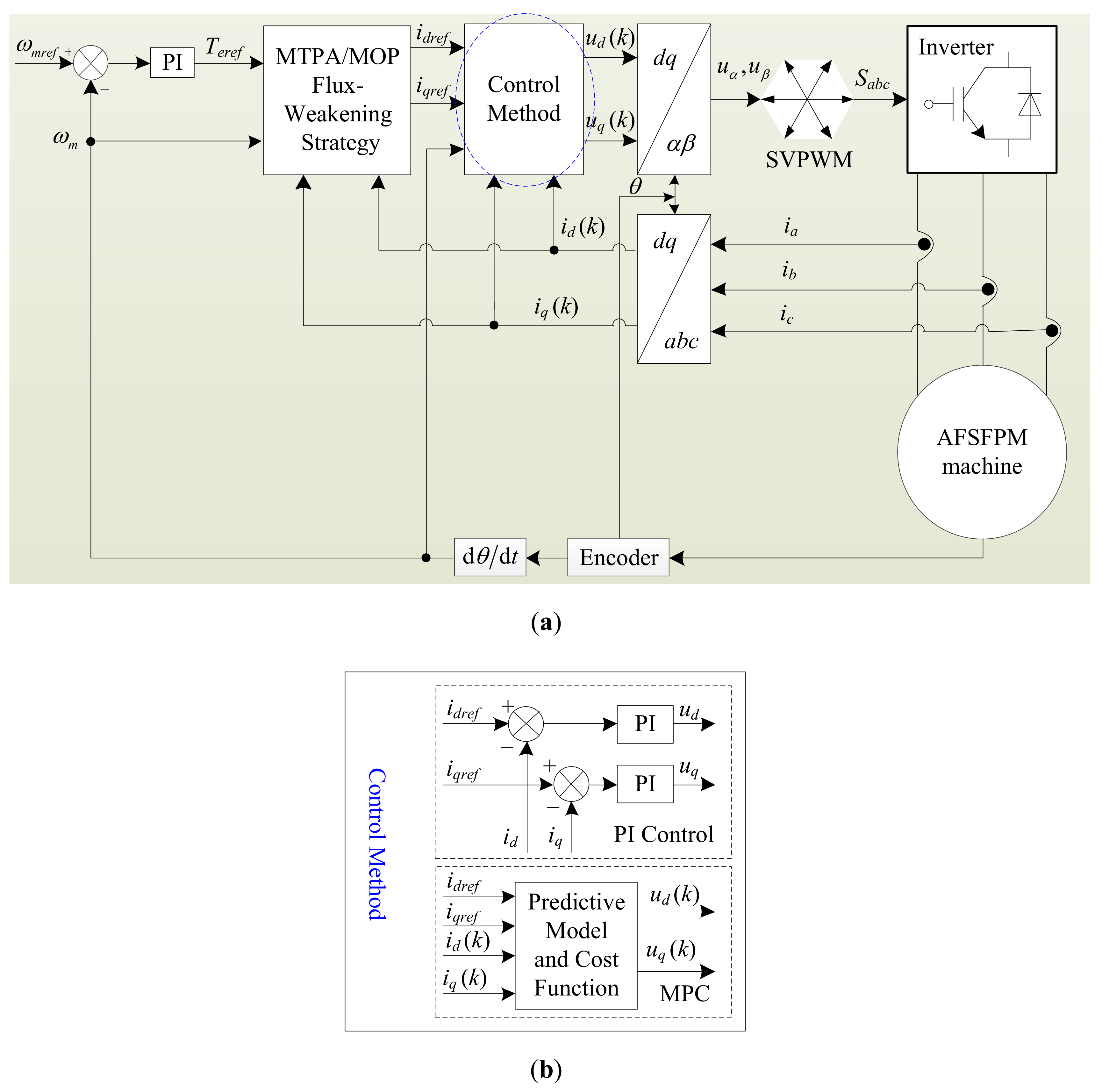
4. Model Predictive Control

4.1. Discrete Model of AFSFPM Machine

As seen from Figure 6, the open circuit PM flux linkage, the back-EMF and the inductance of the AFSFPM machine are approximately sinusoidal. So, the AFSFPM machine is very suitable for brushless AC operation. However, the PMs are located in the stator of the AFSFPM machine, which does not generate rotational magnetomotive force. Hence, the PMs in the stator are assumed in the rotor in this study and the rotor-flux-oriented control method is employed to control the AFSFPM machine, which called virtual stator-PM-flux-oriented in the rotor reference frame. Neglecting the influence of the temperature, iron saturation, eddy-current loss and magnetic hysteresis loss, the AFSFPM machine is analyzed based on the rotor-fixed d-q reference frame, as in Figure 7. According to the axial switched-flux principle, the three-phase PM flux linkage and back-EMF waveforms, the continuous-time models of the AFSFPM machine in the rotor-fixed d-q reference frame are described by (11) to (12).
Considering the current as state variable, the state-space equation of AFSFPM machine can be written as
[ d i d d t d i q d t ] = [ R s L d ω e L q L d ω e L d L q R s L q ] [ i d i q ] + [ 1 L d 0 0 1 L q ] [ u d u q ] + [ 0 ω e ψ p m L q ]
The electromagnetic torque equation is derived as
T e = 3 2 p i q [ ψ p m + ( L d L q ) i d ] = 3 2 p i q [ ψ p m + L d ( 1 ρ ) i d ]  
where ud, uq, id, iq are the d-, q-axis components of stator voltages and currents, respectively. Rs is the stator-phase resistance and ψpm is the PM flux by the PMs in stator. Ld, Lq are the d- and q-axis components of the synchronous inductance, respectively. ωe is the electrical rotation velocity, respectively. Te is the electromagnetic torque. p and ρ are the number of poles and the saliency ratio, respectively.
The Euler method was often used to obtain a simple discrete time model without introducing any unwanted additional nonlinear terms. Thus, the AFSFPM machine can be modeled in discrete time based on the Euler method, which can be gotten as
[ i d ( k + 1 ) i q ( k + 1 ) ] = [ 1 T s R s L d ω e T s L q L d ω e T s L d L q 1 T s R s L q ] [ i d ( k ) i q ( k ) ] + [ T s L d 0 0 T s L q ] [ u d ( k ) u q ( k ) ] + [ 0 ω e T s ψ p m L q ]
where Ts is the sampling period. id (k + 1), iq (k + 1) are the d- and q-axis current predicted value at the k + 1 moment.
The Equation (13) can be written as state-space equation
x ( k + 1 ) = A x ( k ) + B u ( k ) + C
where
x ( k ) = [ i d ( k ) i q ( k ) ] , u ( k ) = [ u d ( k ) u q ( k ) ] , A = [ 1 T s R s L d ω e T s L q L d ω e T s L d L q 1 T s R s L q ] , B = [ T s L d 0 0 T s L q ] , C = [ 0 ω e T s ψ p m L q ]

4.2. Cost Function

In this paper, the space vector pulse width modulation (SVPWM)-MPC method is used to study the operating performance of the AFSFPM machine drive system. For the SVPWM-MPC of the AFSFPM machine, the control goal can be prescribed by the cost function. Considering the accuracy for the reference current tracking and the current limitation, the cost function is defined as
H = ( i d r e f i d ( k + 1 ) ) 2 + ( i q r e f i q ( k + 1 ) ) 2 + g ( i d ( k + 1 ) , i q ( k + 1 ) )
g ( i d ( k + 1 ) , i q ( k + 1 ) ) = { | i d | > i lim   or   | i q | > i lim 0 | i d | i lim   and   | i q | i lim
In Equation (16), the first component is evaluation the difference between the reference current and predictive current and the second component is evaluation the current constraint condition.
In order to predict accurately the k + 1 moment current id (k + 1) and iq (k + 1), substituting Equation (13) into (15) and setting the partial differentiation of (15) with respect to the ud and uq to zeros yield and the following equation can be obtained as
{ H u d ( k ) = 2 T s L d ( i d ( k + 1 ) i d r e f ) = 0 H u q ( k ) = 2 T s L q ( i q ( k + 1 ) i q r e f ) = 0
According to Equation (17), the following equation is gotten as
{ i d ( k + 1 ) = i d r e f i q ( k + 1 ) = i q r e f

4.3. Current Predictive Model

Combining Equations (13) and (18), the stator reference voltage which produces required stator currents can be expressed as
{ u d ( k ) = L d T s i d r e f ( L d T s R s ) i d ( k ) ω e L q i q ( k ) u q ( k ) = L d T s i q r e f ( L q T s R s ) i q ( k ) + ω e L d ( k ) i d ( k ) + ω ψ p m
where idref, iqref are the d-, q-axes reference current at the sampling step k + 1 respectively.
According to the current predictive model of equation (19), the stator voltages ud (k) and uq (k) at the k moment can be obtained. Substituting the ud (k) and uq (k) into the SVPWM algorithm, which generates the switching signal.

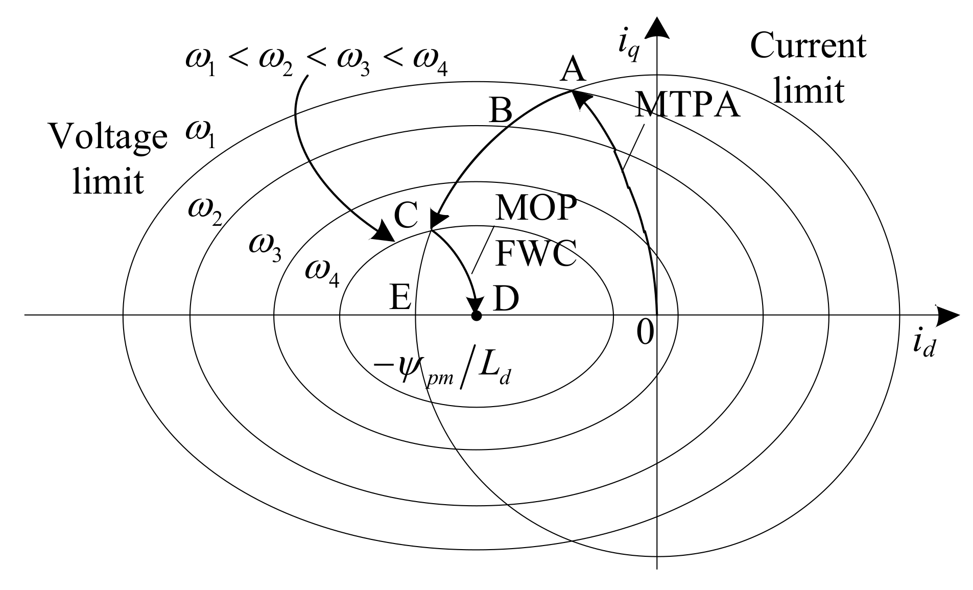
4.4. Reference Current Calculation

In general, the AFSFPM machines for EV/HEV applications are controlled frequently with maximum output torque and power mode. So, the maximum torque per ampere (MTPA) control strategy is adopted in constant toque region and the maximum output power flux-weakening control method is employed in constant power region, as shown in Figure 8.

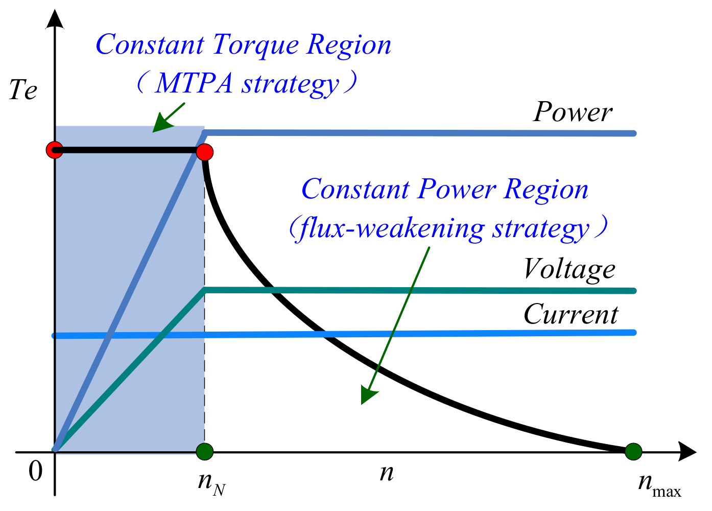
4.4.1. Constant Torque Region

In order to improve torque output capability of the AFSFPM machine, the MTPA strategy, which the torque and current ratio is largest for the same torque and speed, is adopted in constant torque region. It is necessary to identify the distribution principle of the optimum reference current by using the extended Lagrange method, as detailed below
L ( i d , i q , λ ) = i d 2 + i q 2 + λ { 3 2 p i q [ ψ p m + ( L d L q ) i d ] T e }
where λ denotes the Lagrange multipliers.
Setting the partial differentiation of (20) with respect to the id, iq and λ to zeros yield, the following equation can be obtained as
{ L i d = 2 i d + 3 2 λ p ( L d L q ) i q = 0 L i q = 2 i q + 3 2 λ p [ ψ p m + ( L d L q ) i d ] = 0 L λ = 3 2 p [ ψ p m i q + ( L d L q ) i d i q ] T e = 0
According to Equation (21), the reference current in constant torque region can be gotten as (Appendix A)
{ i d r e f = ψ p m 4 ( L q L d ) 2 i q r e f 2 + ψ p m 2 2 ( L q L d ) i q r e f = [ 4 T e 2 6 p ψ p m T e i q r e f 9 ( L q L d ) 2 p 2 ] 1 4
Substituting Equation (22) into (19), the stator voltages ud (k) and uq (k) can be gotten in the constant torque region.

4.4.2. Constant Power Region

The stator voltage and current limitation of AFSFPM machine are amplitude limit with a definite maximum value, which can be expressed as
{ u d 2 + u q 2 u s max 2 = ( U d c 3 ) 2 i d 2 + i q 2 i s max 2
where ismax, usmax are the phase voltage and current amplitude, respectively. Udc is the dc link voltage. The current limitation is a circle of radius ismax and the center is the origin of coordinate. The voltage limit is an ellipse of half axes a = U d c 3 L d ω e and b = U d c 3 L q ω e and of center ( ψ p m L d , 0), as seen in Figure 9.
Ignoring the resistance voltage drops of the armature windings at steady-state operation in constant power region, Equation (11) is rewritten as
{ u d = ω e L q i q u q = ω e ( ψ p m + L d i d )
Substituting Equation (24) to (23), the following equation can be obtained as
( ω e L q i q ) 2 + ( ω e L d i d + ω e ψ p m ) 2 ( U d c 3 ) 2
We can still write Equation (25) as
ω e U d c 3 ( L q i q ) 2 + ( L d i d + ψ p m ) 2
According to Equations (12) and (26), when the maximum speed ωe is achieved, the reference current in constant power region can be obtained as (Appendix B)
{ i d r e f = ( U d c 3 ω e ) 2 ( L q i q r e f ) 2 ψ p m L d i q r e f = 2 T e 3 p [ ψ p m + ( L d L q ) i d r e f ]
As described in Figure 9, when the operating point moves from A to C, the AFSFPM machine operates in constant power region I. The above-mentioned flux-weakening control strategy, so-called traditional flux-weakening control strategy, is adopted. From C to E or D, the machine operates in constant power region II. To broaden the range of speed-regulation and increase load capability, a maximum output power flux-weakening control (MOP-FWC) strategy for the AFSFPM machine is presented in constant power region II and the operating point moves from C to D.
The power equation of AFSFPM machine is expressed as
P e = 3 2 p ω e i q [ ψ p m + ( L d L q ) i d ]
Based on Equations (25) and (28), the Lagrange function with constant back-EMF in constant power region is constructed as
L = 1.5 p ω e i q [ ψ p m + ( L d L q ) i d ] + λ { ( U d c 3 ) ω e ( ψ p m + L d i d ) 2 + ( L q i q ) 2 }
Setting the partial differentiation of (29) with respect to the id, iq and λ to zeros yield, the following equation can be gotten as
{ L i d = 3 2 p ω e ( L d L q ) i q λ ω e L d ( ψ p m + L d i d ) ( ψ p m + L d i d ) 2 + ( L q i q ) 2 = 0 L i q = 3 2 p ω e [ ψ p m + ( L d L q ) i d ] λ ω e L q 2 i q ( ψ p m + L d i d ) 2 + ( L q i q ) 2 = 0 L λ = U d c 3 ω e ( ψ p m + L d i d ) 2 + ( L q i q ) 2 = 0
According to Equation (30), the reference current can be obtained as
{ i d r e f = ψ p m L d + Δ i d i q r e f = ( U d c / 3 ω e ) 2 ( L d Δ i d ) 2 L q
where
Δ i d = ρ ψ p m ± ρ 2 ψ p m 2 + 8 ( ρ 1 ) 2 ( U d c 3 ω e ) 2 4 ( ρ 1 ) L d  
In order to study the operating characteristics of AFSFPM machine drive system in each operation region with different control strategies, on the basis of the above-mentioned analysis, the control system of AFSFPM machine under MPC and traditional PI control is established, as shown in Figure 10.
Figure 10a describes the control system of AFSFPM machine and two kind of control method of the traditional PI control and MPC are shown in Figure 10b. Based on the error current between the reference current and real current, the PI controllers are used to produce the reference voltage under the traditional PI control method. To achieve the MPC objective in each operating region of the AFSFPM machine, the different multi-objective cost functions, considering such as the MTPA strategy and torque in constant torque region and the MOP-FWC strategy as well as voltage limitation in constant power region, are designed. Multiple right weight coefficients are chosen and analyzed to optimize the control efficiency of MPC and the performance of control system.

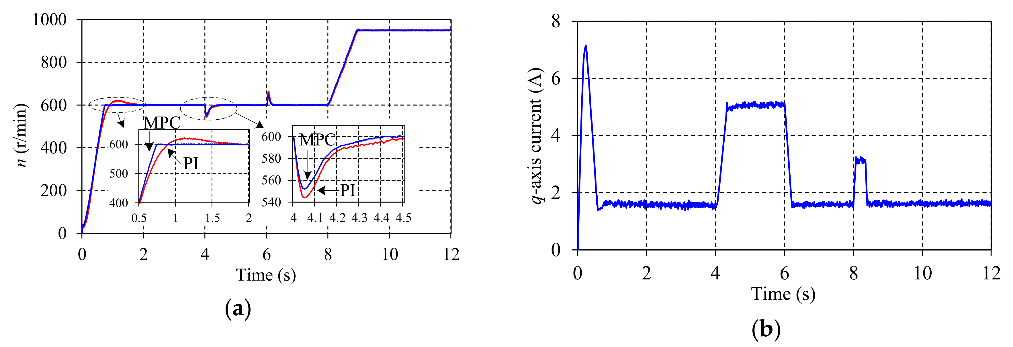
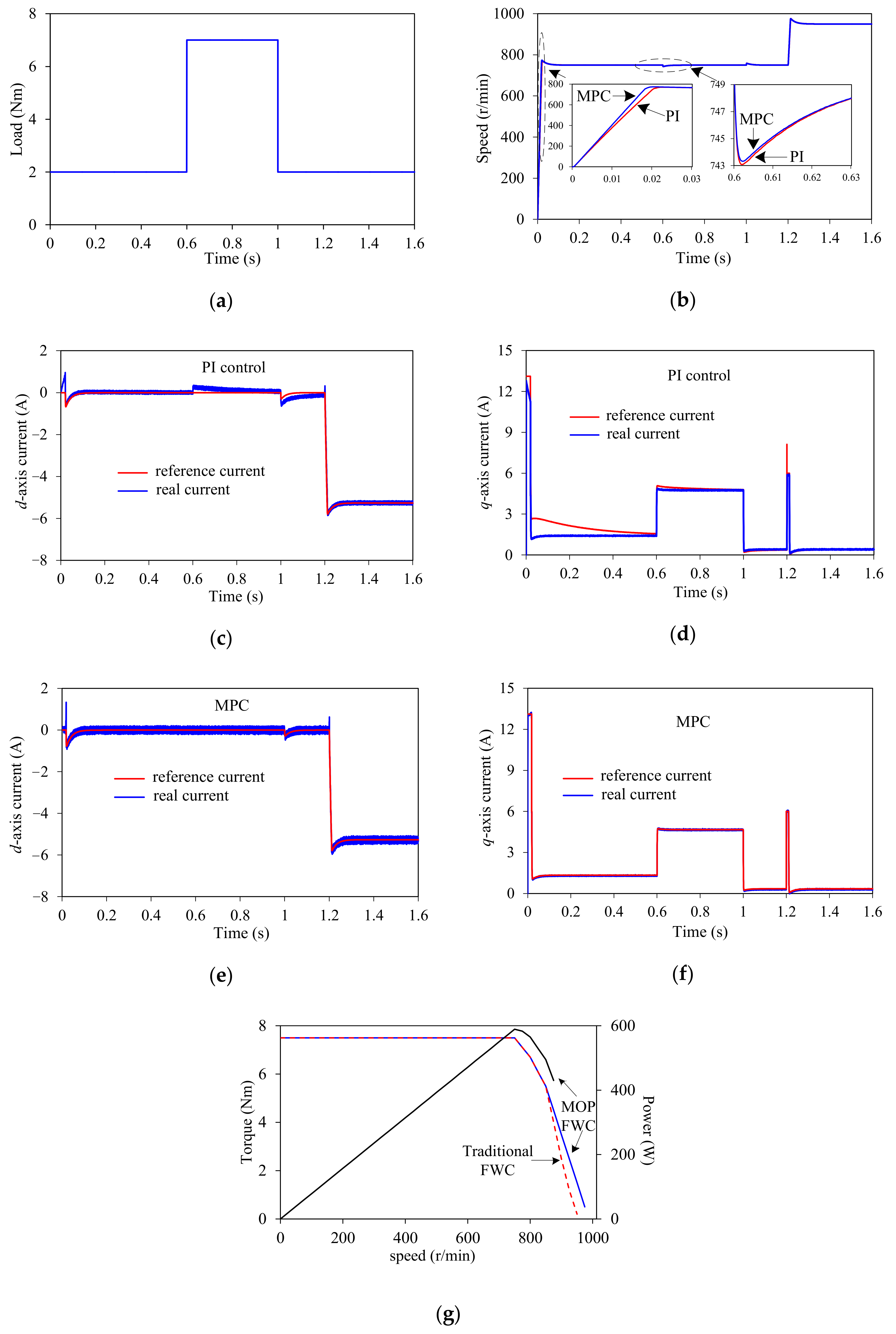
5. Simulation and Experiment

5.1. Simulation Analysis

Based on MATLAB/Simulink, a simulation system is established and conducted to study the operating performance of an AFSFPM machine prototype and to verify the effectiveness of the proposed control scheme using the parameters of the experimental prototype shown in Table 2.
Firstly, a reference speed of 750 r/min and a load of 2 N·m are given and the load is increased to 7 N·m at 0.6 s and decrease to 2 N·m at 1 s respectively. The given speed is increased to 950 r/min at 1.2 s and the simulation results adopting the MPC method are shown in Figure 11 and compared to the traditional PI control method.
The MTPA and flux-weakening strategies are employed in constant torque and constant power region, respectively. As seen from Figure 11, to accelerate the starting process, the torque is increased to the maximum value and the q-axis current is about 12.8 A. Because of the MTPA control, the d-axis current is −0.8 A. When the machine operates at 750 r/min steadily, the d-, q-axis currents are about −0.2 A and 1.35 A respectively. The speed has a ripple with the increasing or decreasing load and returns quickly to the given command after adjustment. The machine operates at the constant power region I after 1.2 s and the traditional flux-weakening strategy, namely constant back-EMF strategy is adopted. When the speed achieves 875 r/min, the MOP flux-weakening strategy is used to broaden the speed operation range. Due to the limitation of d-axis inductance and current, when the d-axis current is −5.2 A, the speed achieves the maximum of 950 r/min. The torque-speed and power-speed envelopes are depicted in Figure 11g.
To analyze and access the dynamic response and robustness, the different speed references and load steps are applied to the drive system and the load step is considered as a disturbance. It can be seen that the predictive current can track the reference current quickly and accurately and the starting time is shorter and the anti-load-disturbance capability is better under the proposed MPC method in comparison with the PI control method. The drive system of the AFSFPM machine has fast dynamic response ability and excellent robustness and the influences of the cogging torque and load-disturbance on the performance of drive system are reduced. The validity of the proposed control methods is verified.

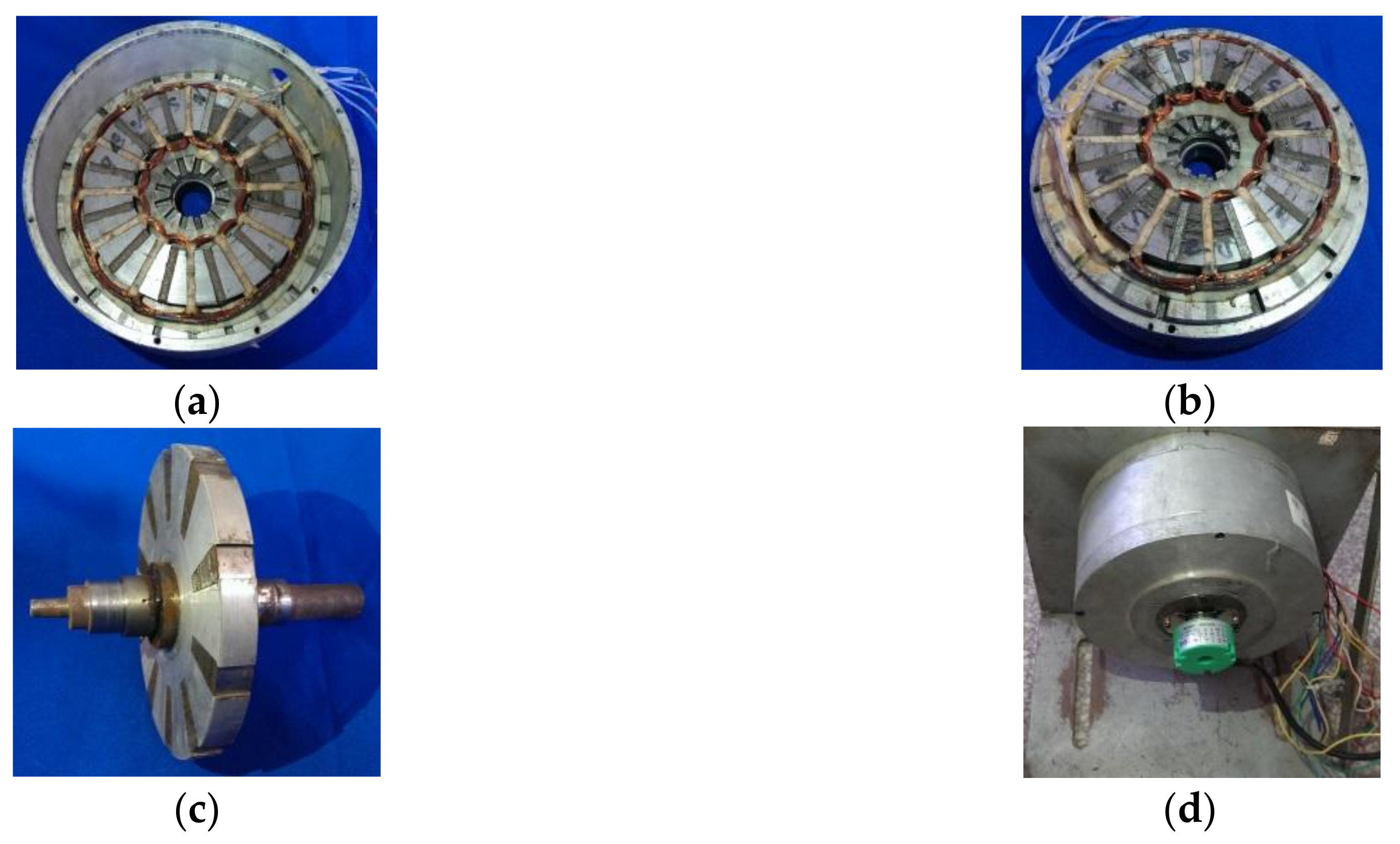
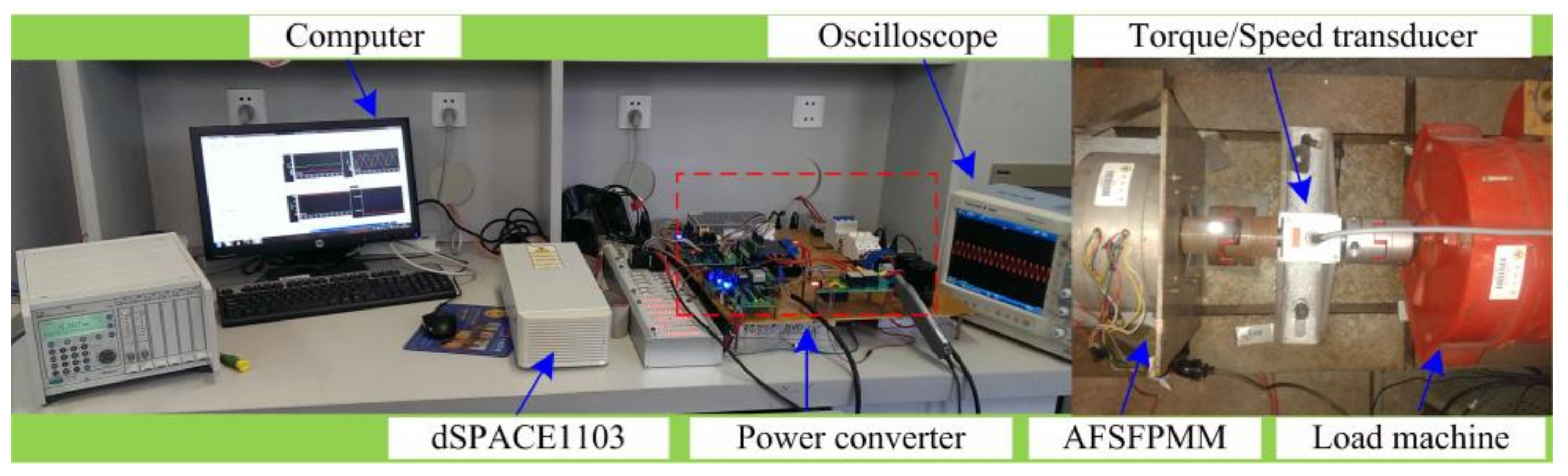
5.2. Experimental Research

On the basis of the optimized parameters shown in Table 1, the prototype of the AFSFPM machine has been manufactured, as seen in Figure 12. The prototype contains double stators and single rotor.
As shown in Figure 13, the experimental platform for the AFSFPM machine based on the dSPACE 1103 is designed and established and the proposed control algorithm and the performance of AFSFPM machine have been tested and verified.
On the basis of the experimental platform shown in Figure 13, the EMF and cogging torque of the AFSFPM machine are measured and analyzed and the results are exhibited in Figure 14.
As seen from Figure 13a, three-phase EMF are sinusoidal distribution and symmetrical and the amplitude under no-load at rated speed of 750 r/min is about 82 V, which is lower than the FE calculation due to the end effect. As shown in Figure 13b, because of the flux-focusing and machining accuracy, the real cogging torque of 1.15 N·m is larger than the FE calculation value of 0.95 N·m. The measured results basically match up with the theoretical analysis and FE calculation. Therefore, the AFSFPM machine is very suitable for brushless AC operation.
The experimental results of the dynamic characteristics with the MPC and PI method in the whole speed operating region are described in Figure 15. With a given reference speed of 600 r/min with no-load, the load increases and decreases by 6 N·m at 4 s and 6 s, respectively. At 8 s, the speed is increased to 950 r/min.
As can be seen from Figure 15, the MTPA strategy is employed at the starting and when the machine operates at steady-condition, the id and iq are about −0.2 A and 1.5 A respectively due to the cogging torque and axle friction. The starting time of 0.75 s is shorter and the speed ripple is smaller with the MPC method than under the PI method. There is a speed fluctuation under the increasing or decreasing load but the speed fast returns to the reference speed command after adjustment and the recovery time is shorter and anti-load disturbance capability is better by using the MPC method than the PI method. After 8.35 s, the machine operates at constant power region over the rated speed of 750 r/min and the constant back-EMF flux-weakening strategy is adopted. When the speed achieves 875 r/min, the MOP flux-weakening strategy is used to broaden the operating range. The maximum speed achieves 950 r/min under the MOP flux-weakening strategy, which is larger than 920 r/min under the traditional flux-weakening strategy with the same load. Figure 15d shows the torque-speed and power-speed envelopes under two different flux-weakening strategies of the traditional and MOP strategies. Compared to under the traditional strategy, the load capacity is improved and the speed-regulation range is broadened by using the MOP strategy. Under the same load and speed, the copper loss of the AFSFPM is reduced by adopted the MTPA and MOP strategies and the efficiency is improved.
According to the above-mentioned research, the experimental results are consistent with the theoretical calculation and simulation calculations. The operating performance of the AFSFPM machine and the effectiveness of the proposed control methods are verified. The operating characteristics of the AFSFPM machine including the cogging torque, power/torque density as well as speed-regulation range will be further optimized and the results will be reported in future paper.

6. Conclusions

This paper investigated a three-phase 12/10 AFSFPM machine with dual-stator-single-rotor structure including optimization design, analysis and control, which is interesting for EV/HEV applications. The operating principle and design procedure of the AFSFPM machine were analyzed in detailed and the electromagnetic characteristics were studied by 3-D FE method. A prototype has been manufactured and tested and the measured EMF and cogging torque are consistent with the predicted results using FE method, which is suitable for brushless AC operation. Based on the virtual stator-PM-flux-oriented control, the operating performance of the AFSFPM machine was studied in the entire speed operating region. It can be concluded that the MTPA strategy takes advantage of the reluctance torque and maximizes the load capability and the MOP flux-weakening strategy broadens the operating range of constant power operation region. Furthermore, the anti-load disturbance capability and dynamic response are improved by using the MPC method. The feasibility and effectiveness of the proposed control method and the performance of the AFSFPM machine were verified by experimental results. The results show the drive system of the AFSFPM machine can provide high power/torque density, excellent load capacity, fast dynamic response, good tracking capability and strong robustness. The key conclusion from this research is that the AFSFPM machine has lot of potential to be useful for many traction system applications such as EV or HEV.

Author Contributions

All authors have contributed to this work. J.Z. presented of the idea of the research, finished the machine design and experiment. X.Q. and M.J. helped to finish the experiments. The readability of the manuscript was improved by M.L. and N.L. All authors revised and approved the publication.

Funding

National Natural Science Foundation of China under Grant 50977010.

Acknowledgments

This work was supported by the National Natural Science Foundation of China under Grant 51707156, the Nature Science Basic Research Plan in Shaanxi Province of China under Grant 2017JQ5077 and the China Postdoctoral Science Foundation under Grant 2018M633645XB.

Conflicts of Interest

The authors declare no conflicts of interest.

Appendix A

{ L i d = 2 i d + 3 2 λ p ( L d L q ) i q = 0 ( A 1.1 ) L i q = 2 i q + 3 2 λ p [ ψ p m + ( L d L q ) i d ] = 0 ( A 1.2 ) L λ = 3 2 p [ ψ p m i q + ( L d L q ) i d i q ] T e = 0 ( A 1.3 )
According to Equation (A1), the following equation can be obtained as
{ 3 4 λ p = ( L d L q ) i q i d ( A 2.1 ) 3 4 λ p = [ ψ p m + ( L d L q ) i d ] i q ( A 2.2 ) 3 2 p [ ψ p m i q + ( L d L q ) i d i q ] T e = 0 ( A 2.3 )
Substituting (A2.2) into (A2.1), the following equation can be gotten as
{ ( L d L q ) i q i d = [ ψ p m + ( L d L q ) i d ] i q ( A 3.1 ) 3 2 p [ ψ p m i q + ( L d L q ) i d i q ] T e = 0 ( A 3.2 )
{ i d = ψ p m ψ p m 2 + 4 ( L q L d ) 2 i q 2 2 ( L q L d ) ( A 4.1 ) T e = 3 2 p i q [ ψ p m + ( L d L q ) i d ] ( A 4.2 )
Substituting (A4.1) into (A4.2), the reference current is obtained as
{ i d r e f = ψ p m 4 ( L q L d ) 2 i q r e f 2 + ψ p m 2 2 ( L q L d ) ( A 5.1 ) i q r e f = [ 4 T e 2 6 p ψ p m T e i q r e f 9 ( L q L d ) 2 p 2 ] 1 4 ( A 5.2 )
Equation (A5.2) is a quartic equation with respect to iqref and the newton iteration method is used to solve Equation (A5.2). According to the different Te, the iqref can be obtained off-line. Finally, we created a table about the relationship between the Te and iqref and the table is used to search the appropriate iqref on-line base on the different reference torque Te. Substituting the iqref into the Equation (A5.2), the idref can be gotten.

Appendix B

The stator voltage equation of the AFSFPM machine is expressed as
{ u d = R s i d + L d d i d d t ω e L q i q u q = R s i q + L q d i q d t + ω e ( ψ p m + L d i d )
Under the steady-state operating condition, Equation (A6) can be rewritten as
{ u d = R s i d ω e L q i q u q = R s i q + ω e ( ψ p m + L d i d )
Ignoring the resistance voltage drops of the armature windings in constant power region, Equation (A7) is described as
{ u d = ω e L q i q u q = ω e ( ψ p m + L d i d )
The stator voltage limitation of AFSFPM machine can be expressed as
u d 2 + u q 2 u s max 2 = ( U d c 3 ) 2
Substituting Equation (A8) to (A9), the following equation can be obtained as
( ω e L q i q ) 2 + ( ω e L d i d + ω e ψ p m ) 2 ( U d c 3 ) 2
We can still write Equation (A10) as
ω e U d c 3 ( L q i q ) 2 + ( L d i d + ψ p m ) 2
When the maximum speed ωe is achieved, Equation (A11) can be described as
( L q i q ) 2 + ( L d i d + ψ p m ) 2 = U d c 3 ω e
The electromagnet torque equation of the AFSFPM machine is expressed as
T e = 3 2 p i q [ ψ p m + ( L d L q ) i d ] = 3 2 p i q [ ψ p m + L d ( 1 ρ ) i d ]
According to Equations (A12) and (A13), the reference current in constant power region can be obtained as
{ i d r e f = ( U d c 3 ω e ) 2 ( L q i q r e f ) 2 ψ p m L d i q r e f = 2 T e 3 p [ ψ p m + ( L d L q ) i d r e f ]
Equation (A14) presents the relationship between the idref and iqref. In this paper, a simplified constant back-EMF flux-weakening control strategy is adopted as follows.
Because the id is very small under the rated operating condition, the approximate q-axis rated voltage uqN based Equation (A8) can be expressed as
u q N = ω e N ψ p m
where ωeN is the rated synchronous electrical rotation speed.
In order to obtain the maximum speed in constant power region, we consider that Equation (A8) is approximate equal to Equation (A15) (uq = uqN) and the following equation can be obtained as
ω e N ψ p m = ω e ( L d i d + ψ p m )
According to Equation (A16), the d-axis reference current can be gotten as
i d r e f = ψ p m L d ( ω e N ω e 1 )
Substituting Equation (A17) into (A13), the q-axis reference current can be obtained as
i q r e f = 2 T e L d ω e 3 p ψ p m [ ω e N ( L d L q ) + L q ω e ]
So, the reference current in constant power region can be expressed as
{ i d r e f = ψ p m L d ( ω e N ω e 1 ) i q r e f = 2 T e L d ω e 3 p ψ p m [ ω e N ( L d L q ) + L q ω e ]

References

  1. Chan, T.F.; Lai, L.L. An axial-flux permanent-magnet synchronous generator for a direct-coupled wind-turbine system. IEEE Trans. Energy Convers. 2007, 22, 86–94. [Google Scholar] [CrossRef]
  2. Marignetti, F.; Colli, V.D.; Coia, Y. Design of axial flux PM synchronous machines through 3-D coupled electromagnetic thermal and fluid-dynamical finite-element analysis. IEEE Trans. Ind. Electron. 2008, 55, 3591–3601. [Google Scholar] [CrossRef]
  3. Capponi, F.G.; De Donato, G.; Caricchi, F. Recent advances in axial-flux permanent-magnet machine technology. IEEE Trans. Ind. Appl. 2012, 48, 2190–2205. [Google Scholar] [CrossRef]
  4. De Bisschop, J.; Sergeant, P.; Hemeida, A.; Vansompel, H.; Dupré, L. Analytical model for combined study of magnet demagnetization and eccentricity defects in axial flux permanent magnet synchronous machines. IEEE Trans. Magn. 2017, 53, 8107712. [Google Scholar] [CrossRef]
  5. Hemeida, A.; Taha, M.; Abdallh, A.A.E.; Vansompel, H.; Dupré, L.; Sergeant, P. Applicability of fractional slot axial flux permanent magnet synchronous machines in the field weakening region. IEEE Trans. Energy Convers. 2017, 32, 111–121. [Google Scholar] [CrossRef]
  6. Ogidi, O.O.; Barendse, P.S.; Khan, M.A. Influence of rotor topologies and cogging torque minimization techniques in the detection of static eccentricities in axial-flux permanent-magnet machine. IEEE Trans. Ind. Appl. 2017, 53, 161–170. [Google Scholar] [CrossRef]
  7. Kappatou, J.C.; Zalokostas, G.D.; Spyratos, D.A. 3-D FEM Analysis, Prototyping and Tests of an Axial Flux Permanent-Magnet Wind Generator. Energies 2017, 10, 1269. [Google Scholar] [CrossRef]
  8. Hoang, E.; Ben-Ahmed, A.H.; Lucidarme, J. Switching flux permanent magnet polyphased synchronous machines. In Proceedings of the 7th Europe Conference Power Electronics and Applications, Trondheim, Norway, 8–10 September 1997; pp. 903–908. [Google Scholar]
  9. Zhu, Z.Q.; Chen, J.T. Advanced switched-flux permanent magnet brushless machines. IEEE Trans. Magn. 2010, 46, 1447–1453. [Google Scholar] [CrossRef]
  10. Yu, F.; Cheng, M.; Chau, K.T.; Li, F. Control and Performance Evaluation of Multiphase FSPM Motor in Low-Speed Region for Hybrid Electric Vehicles. Energies 2015, 8, 10335–10353. [Google Scholar] [CrossRef] [Green Version]
  11. Dupas, A.; Hlioui, S.; Hoang, E.; Gabsi, M.; Lecrivain, M. Investigation of a new topology of hybrid-excited switched-flux machine with static global winding: experiments and modeling. IEEE Trans. Ind. Appl. 2016, 52, 1413–1421. [Google Scholar]
  12. Wu, Z.Z.; Zhu, Z.Q. Analysis of magnetic gearing effect in partitioned stator switched flux PM machines. IEEE Trans. Energy Convers. 2016, 31, 1239–1249. [Google Scholar] [CrossRef]
  13. Zhu, X.; Shu, Z.; Quan, L.; Xiang, Z.; Pan, X. Multi-objective optimization of an outer-rotor V-shaped permanent magnet flux switching motor based on multi-level design method. IEEE Trans. Magn. 2016, 52, 1–8. [Google Scholar] [CrossRef]
  14. Hua, W.; Zhang, H.; Cheng, M.; Meng, J.; Hou, C. An outer-rotor switched-flux permanent-magnet machine with wedge-shaped magnets for in-wheel light traction. IEEE Trans. Ind. Electron. 2017, 64, 69–80. [Google Scholar] [CrossRef]
  15. Zhao, J.; Zheng, Y.; Zhu, C.; Liu, X.; Li, B. A Novel Modular-Stator Outer-Rotor Flux-Switching Permanent-Magnet Motor. Energies 2017, 10, 937. [Google Scholar] [CrossRef]
  16. Hao, L.; Lin, M.; Li, W.; Luo, H.; Fu, X.; Jing, P. Novel dual-rotor axial field switched-flux permanent magnet machine. IEEE Trans. Magn. 2012, 48, 4232–4235. [Google Scholar] [CrossRef]
  17. Hao, L.; Lin, M.; Xu, D.; Fu, X.; Zhang, W. Static Characteristics of a Novel Axial Field Switched-flux Permanent Magnet Motor with Three Stator Structures. IEEE Trans. Magn. 2014, 50, 4002604. [Google Scholar] [CrossRef]
  18. Zhang, W.; Lin, M.; Xu, D.; Fu, X.; Hao, L. Novel fault-tolerant design of axial field switched-flux permanent magnet machine. IEEE Trans. Appl. Supercond. 2014, 24, 0503804. [Google Scholar]
  19. Zhang, W.; Liang, X.; Lin, M.; Hao, L.; Li, N. Design and analysis of novel hybrid-excited axial field switched-flux permanent magnet machines. IEEE Trans. Appl. Supercond. 2016, 26, 1–5. [Google Scholar]
  20. Zhao, W.; Lipo, T. A.; Kwon, B.I. A novel dual-rotor, axial field, fault-tolerant switched-flux permanent magnet machine with high-torque performance. IEEE Trans. Magn. 2015, 51, 7112204. [Google Scholar] [CrossRef]
  21. Kim, J.H.; Li, Y.; Sarlioglu, B. Novel six-slot four-pole axial switched-flux permanent magnet machine for electric vehicle. IEEE Trans. Transp. Electrification 2017, 3, 108–117. [Google Scholar] [CrossRef]
  22. Syed, Q.A.S.; Kurtović, H.; Hahn, I. New single-phase flux switching axial flux Permanent magnet motor. IEEE Trans. Magn. 2017, 53, 8209505. [Google Scholar] [CrossRef]
  23. Zhao, J.; Lin, M.; Xu, D.; Hao, L.; Zhang, W. Vector control of a hybrid axial field switched-flux permanent magnet machine based on particle swarm optimization. IEEE Trans. Magn. 2015, 51, 1–4. [Google Scholar]
  24. Hasanien, H.M.; Abd-Rabou, A.S.; Sakr, S.M. Design optimization of transverse flux linear motor for weight reduction and performance improvement using response surface methodology and genetic algorithms. IEEE Trans. Energy Convers. 2010, 25, 598–605. [Google Scholar] [CrossRef]
  25. Jędryczka, C.; Knypiński, Ł.; Demenko, A.; Sykulski, J.K. Methodology for Cage Shape Optimization of a Permanent Magnet Synchronous Motor Under Line Start Conditions. IEEE Trans. Magn. 2018, 54, 8102304. [Google Scholar] [CrossRef]
  26. Lei, G.; Xu, W.; Hu, J.F.; Zhu, J.G.; Guo, Y.G.; Shao, K.R. Multilevel design optimization of a FSPMM drive system by using sequential subspace optimization method. IEEE Trans. Magn. 2014, 50, 7016904. [Google Scholar] [CrossRef]
  27. Ma, B.; Lei, G.; Zhu, J.; Guo, Y.; Liu, C. Application-Oriented Robust Design Optimization Method for Batch Production of Permanent-Magnet Motors. IEEE Trans. Ind. Electron. 2018, 65, 1728–1739. [Google Scholar] [CrossRef]
  28. Lei, G.; Zhu, J.G.; Guo, Y.G.; Liu, C.C.; Ma, B. A Review of Design Optimization Methods for Electrical Machines. Energies 2017, 10, 1962. [Google Scholar] [CrossRef]
  29. Morel, F.; Lin-Shi, X.; Retif, J.M.; Allard, B.; Buttay, C. A comparative study of predictive current control schemes for a permanent-magnet synchronous machine drive. IEEE Trans. Ind. Electron. 2009, 56, 2715–2728. [Google Scholar] [CrossRef]
  30. Formentini, A.; Trentin, A.; Marchesoni, M.; Zanchetta, P.; Wheeler, P. Speed finite control set model predictive control of a PMSM fed by matrix converter. IEEE Trans. Ind. Electron. 2015, 62, 6786–6796. [Google Scholar] [CrossRef]
  31. Siami, M.; Arab Khaburi, D.; Rodriguez, J. Simplified finite control set-model predictive control for matrix converter-fed PMSM drives. IEEE Trans. Power Electron. 2018, 33, 2438–2446. [Google Scholar] [CrossRef]
  32. Siami, M.; Khaburi, D.A.; Rodríguez, J. Torque ripple reduction of predictive torque control for PMSM drives with parameter mismatch. IEEE Trans. Power Electron. 2017, 32, 7160–7168. [Google Scholar] [CrossRef]
  33. Wang, W.; Zhang, J.; Cheng, M. Common model predictive control for permanent-magnet synchronous machine drives considering single-phase open-circuit fault. IEEE Trans. Power Electron. 2017, 32, 5862–5872. [Google Scholar] [CrossRef]
  34. Hao, L.; Lin, M.; Zhao, X.; Fu, X.; Zhu, Z.Q.; Jin, P. Static characteristics analysis and experimental study of a novel axial field switched-flux permanent magnet generator. IEEE Trans. Magn. 2012, 48, 4212–4215. [Google Scholar] [CrossRef]
  35. Hao, L.; Lin, M.; Xu, D.; Li, N.; Zhang, W. Cogging torque reduction of axial-field switched-flux permanent magnet machine by rotor tooth notching. IEEE Trans. Magn. 2015, 51, 1–4. [Google Scholar]
Figure 1. Configuration of axial field switched-flux permanent magnet (AFSFPM) machine and two different stator structures. (a) Topology; (b) Stator exploded view; (c) Parallel PM parallel slot (PPPS) structure; (d) Parallel PM parallel slot (PPPT) structure.
Energies 11 01859 g001
Figure 2. Operating principle of AFSFPM machine. (a) Position a; (b) Position b.
Energies 11 01859 g002
Figure 3. Geometrical parameters of AFSFPM machine.
Energies 11 01859 g003
Figure 4. 3-D finite element analysis (FEA) model of AFSFPM machine.
Energies 11 01859 g004
Figure 5. Magnetic field distribution of PPPS structure at θr = 0°. (a) Armature reaction flux density (i = 3.50 A); (b) PM flux density at no-load (i = 0 A); (c) Flux-strengthening i = 1.75 A); (d) Flux-strengthening i = 3.50 A); (e) Flux-weakening (i = −1.75 A); (f) Flux-weakening (i = −3.50 A).
Energies 11 01859 g005aEnergies 11 01859 g005b
Figure 6. Electromagnetic characteristics. (a) PM flux linkage; (b) Electromotive force (EMF); (c) Cogging torque; (d) Inductance per turn of PPPS structure.
Energies 11 01859 g006
Figure 7. Model of AFSFPM machine in d-q reference frame. (a) Define d- and q-axis; (b) Physical model in d-q reference frame.
Energies 11 01859 g007
Figure 8. Operation region of AFSFPM machine.
Energies 11 01859 g008
Figure 9. Flux-weakening control principle.
Energies 11 01859 g009
Figure 10. Block diagram control system under model predictive control (MPC) and PI control. (a) Control system; (b) Control method.
Energies 11 01859 g010
Figure 11. Simulation results of AFSFPM machine. (a) Load; (b) Speed; (c) d-axis current under PI control; (d) q-axis current under PI control; (e) d-axis current under MPC; (f) q-axis current under MPC; (g) Torque-speed and power-speed envelopes.
Energies 11 01859 g011
Figure 12. Prototype of a 12/10 AFSFPM machine. (a) Stator 1; (b) Stator 2; (c) Rotor; (d) Assembled prototype.
Energies 11 01859 g012
Figure 13. Experimental setup of AFSFPM machine control system.
Energies 11 01859 g013
Figure 14. Measured results of AFSFPM machine. (a) EMF; (b) Cogging torque.
Energies 11 01859 g014
Figure 15. Experimental results of AFSFPM machine. (a) Speed; (b) q-axis current; (c) d-axis current; (d) Measured torque-speed and power-speed envelopes.
Energies 11 01859 g015aEnergies 11 01859 g015b
Table 1. Key Design Parameters of AFSFPM machine.
ItemOriginal ParameterOptimized Parameter
Slot/pole number12/1012/10
Rated output power (W)600600
Rated speed (r/min)750750
Rated current (A)3.53.5
Turns per phase180184
Stator outer diameter (mm), Dso150 150
Stator inner diameter (mm), Dsi8282
Stator axial length (mm), ls2016
Stator yoke thickness (mm), hys73
Rotor axial length (mm), lr17.517.5
Air-gap length (mm), g11
Stator tooth width (°), βt7.57.5
Stator slot width (°), βs7.57.5
Stator magnet thickness (°), βPM7.57.5
Rotor pole width (°), βr7.512.5
Table 2. Parameters of the prototype.
Parameters Value
Slot/pole12/10
Rated power600 W
Rated phase voltage67 V
Rated phase current3.5 A
Rated torque7 N·m
Stator resistance Rs1.5 Ω
d-axis inductance Ld4 mH
q-axis inductance Lq5 mH

