Variable Reactivity Control in Small Modular High Temperature Reactors Using Moderation Manipulation Techniques


1
Department of Materials Science and Engineering, Sir Robert Hadfield Building, The University of Sheffield, Sheffield S10 2TN, UK
2
School of Engineering, The University of Liverpool, Brownlow Hill, Liverpool L69 3BX, UK
*
Author to whom correspondence should be addressed.
Energies 2018, 11(7), 1897; https://doi.org/10.3390/en11071897
Submission received: 11 June 2018
/
Revised: 4 July 2018
/
Accepted: 6 July 2018
/
Published: 20 July 2018
(This article belongs to the Section L: Energy Sources)
Abstract
:With extensive research being undertaken into small modular reactor design concepts, this has brought new challenges to the industry. One key challenge is to be able to compete with large scale nuclear power plants economically. In this article, a novel approach is applied to reduce the overall dependence on fixed burnable poisons during high reactivity periods within a high temperature graphite moderated reactor. To reduce the excess activity, we aim to harden the flux spectrum across the core by removing part of the central moderation column, thus breeding more plutonium, in a later period the flux spectrum is softened again to utilise this plutonium again. This provides a neutron storage effect within the 238U and the resulting breeding of Plutonium. Due to the small size and the annular design of the high temperature reactor, the central reflector is key to the thermalization process. By removing a large proportion of the central reflector, the fuel within the proximity of the central reflector are less likely to receive neutrons within the thermal energy range. In addition to this, the fuel at the extremities of the core have a higher chance of fission due to the higher number of neutrons reaching them. This works as a method of balancing the power distribution between the central and outside fuel pins. During points of low reactivity, such as the end of the fuel cycle, the central reflector can be reinserted and the additionally bred plutonium and U235 at the centre of the core will encounter a higher probability of fission due to more thermal neutrons within this region. By removing the central reflector, this provided a 320 pcm reactivity drop for the duration of the fuel cycle. The plutonium buildup provided additional fissile material up until the central reflector was reinserted. The described method created a two-fold benefit. The overall full power days within the core was increased by ~31 days due to the additional fissile material within the core and secondly the highest loaded power pins saw a 30% power reduction during the removal of the central reflector column.
1. Introduction
The global energy landscape is transforming at a dramatic rate due to legislation promoting the reduction of carbon dependent sources in favour of low carbon or green alternatives. Within the UK there are currently three legally binding acts to promote the transition from a fossil fuel dependent nation, to a minimum reduction of 80% of our carbon footprint by 2050 [1,2,3]. Although the capacity for renewable energy is increasing, there are situations where renewable energy sources are not applicable or not practical. To overcome this, the UK government has taken positive steps to a shift towards nuclear energy with the small modular reactor (SMR) competition [4] and opening up key sites for large nuclear investments [5].
This shift towards nuclear energy has placed the UK in a strong position for future nuclear development, with reputable companies such as Rolls-Royce, Nu-Scale and Westinghouse [5,6,7] all showing interest in proving SMR designs for the UK. However, these companies offer mainly similar technology in their light water reactor (LWR) designs, which are very similar to the traditional reactors already operating globally. This is encouraging in some respects, due to the in-depth knowledge of their behaviour and they are well known by the UK regulator, however, this does not provide any benefits for further technological developments towards generation IV. As a member of the Generation IV International Forum, countries such as the UK are required to be actively contributing towards Generation IV reactor designs, with SMRs being a good opportunity to gain experience in these fields [8]. Another, less known, consortium of UK based companies has put forward an innovative design called the U-Battery towards the SMR competition [9].
The U-Battery is a high temperature reactor (HTR) which is based on a comparable technology, the high temperature engineering test reactor (HTTR) which has been operating since 1990 in Japan [10]. The HTR operates at a slightly lower outlet temperature to that of the Generation IV very high temperature reactor, so advances in this field could be used in Generation IV designs. The basis for this technology is already well known as the UK has already operated an HTR in the form of the DRAGON reactor in the 1960s, a review of other HTR projects can be found in the literature [11]. in addition, the UKs existing fleet of nuclear reactors are all graphite based, gas cooled reactors. This puts the UKs knowledge base in a good position to develop their own HTR. The U-Battery also opens a different type of market to that of the SMR competition, with the capacity only being 10 MWth, this reactor aims for remote location deployment, with the versatility to produce high temperature steam for chemical processes of desalination [12]. Due to the desired function of remote location, the current design suffers from excess reactivity to reach the maximum fuel lifecycle possible.
One of the key aspects of HTRs is their ability to be designed to be “meltdown proof” [13,14], implying that beyond basic design accidents, under no circumstances, will the reactor core’s structural integrity be compromised due to excessive temperatures, thus eliminating the risk of radioactive substances being released from the fuel. This is due to the nature of the HTR fuel which uses carefully designed Tristructural-isotropic (TRISO) particles to withhold fission products [15] in combination with a sufficient surface to volume ratio of the core. The particles do not degrade up to an maximum temperature of around 1900 °C [13] at which point they will release fission products. Designing the core so that this temperature won’t be reached under the worse accidental condition allows for this “meltdown proof” conditions to be met. This has been achieved in the HTR-10 a research reactor produced for the Chinese pebble bed HTR programme [13,16].
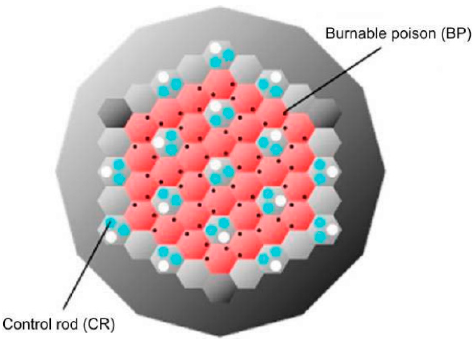
In general, the control of the excess reactivity has implications on safety (possible accident initiation) and operation (distortion of the power distribution). In the case of prismatic HTRs, this reactivity control is typically accomplished in the form of fixed burnable poisons (FBPs) while no explicit excess reactivity control is required in pebble bed type HTRs due to the online fuelling function, allows the reactivity to be controlled. In the case of the HTTR the reactivity control mainly relies on the sixteen control rods. During start up, there are thirty pairs of 50 cm fixed burnable poison rods which are inserted into the top of the core, where the fuel is at the maximum enrichment as shown in Figure 1 [17].
One of the major drawbacks, common for both reactivity control methods, is the loss of neutrons from the poisons which results in reduced core lifetime. This poses the question, is there a method to reduce the excess reactivity, without reducing the core lifetime in the process. In this paper, we investigate the option of reducing neutron moderation across the system. By reducing the moderation, the reactivity of the core will be significantly reduced, due to the lower number of thermal neutrons within the system. In addition to this, with a less thermal system, the 238U has a higher probability of producing 239Pu which can later be re-moderated and utilised for fission once again. This trade off acts as a potential ‘pseudo’ neutron storage system, where when the neutrons are not required, they can be used for breeding and then regained through the bred fissile material.
2. Design Concept
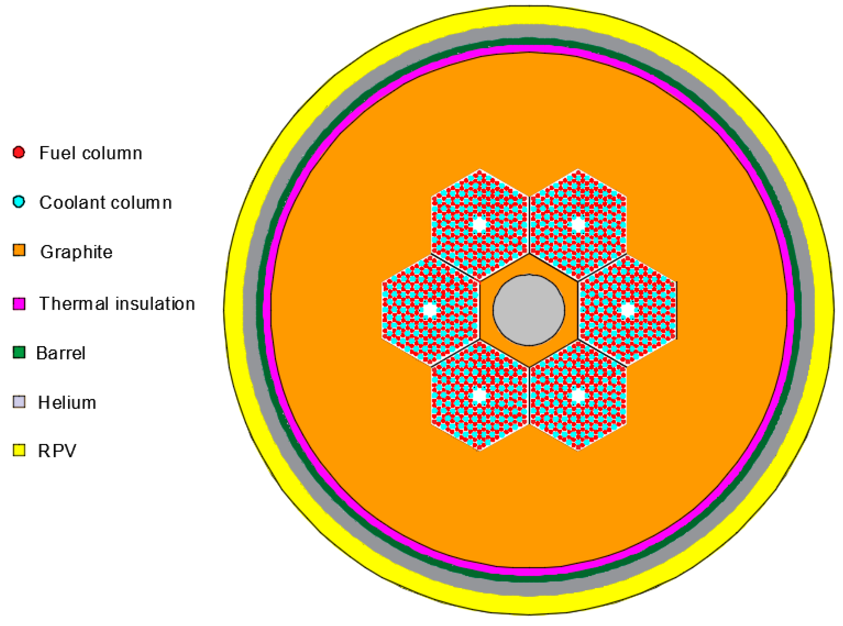
The design chosen to test the new approach is the U-Battery [9], a prismatic HTR SMR based on the prismatic core design. The U-Battery consortium has decided to focus on their 10 MWth design version, so an imitation model has been created as a starting point. The side reflector has been switched to a graphite over a beryllium core due to the ease of deployment and additional benefits witnessed previously [18], as shown in Figure 2. The change from graphite is technologically favourable due to the UK’s leading position with the operation of graphite moderated HTRs. The final design dimensions are also available in the appendices in Table A1, Table A2 and Table A3.
3. Methodology
Due to the U-Battery’s small size, the peak fluxes as well as the resulting power distribution are all heavily dependent on the central reflector (CenRef) of the annular core design. The central reflector block is made solely of graphite, to aid the neutron moderation, this aspect can be utilised by removing the moderation to reduce the criticality by spectral hardening. A similar approach is used during the operation in the boiling water reactor [19], where the reduced coolant flow allows for reduced moderation due to additional void content and thus changes the spectrum to reduce the criticality.
However, graphite is undergoing an altering process which changes physical its conditions during irradiation [20,21]. This implies that graphite needs to be handled carefully over time, so the concept of moving the whole hexagonal block seems to be unrealistic due to the difficulties of mechanical deformation of the material and the structural integrity of the core itself. It is proposed to maintain structural integrity over time by keeping the outside structure of the hexagonal graphite block, only a 26 cm diameter column is cut out of the centre of the central hexagon as depicted in Figure 3. This first approach can be optimised as soon as the first structural integrity evaluation is made available.
We believe, in the case of such a small core, that the removal of a singular volume of graphite is more beneficial than multiple moderator rods. This is due to the simplicity of the control system and the benefits of maintaining a symmetrical flux profile. It should be noted that for additional benefits, the central reflector is not limited to graphite and could be made of more advanced moderating materials such as yttrium hydride.
When considering the task of reactivity control, the requirement for exceptional safety critical systems is paramount. The IAEA safety guide [22] contains regulations that require control rods to be fitted with an interlock to allow the system to be not triggered in unwanted situations. While moving the central reflector block, a similar amount of safety confidence will be required, as the insertion at the wrong time could cause the core to become supercritical. In addition, a fail-safe design system will be essential, it is therefore suggested that the central reflector is inserted from the bottom of the core upwards, this eliminates the risk of the central reflector of entering the core under accidental scenarios.
The control of a central column must be qualified to a similar degree as a control rod drive to pass regulatory standards. This could be achieved in a similar affect as a mechanical jack, where each rotation of the jack is limited to a single turn for the operators input to be limited and controlled. This would provide a high safety factor and remove the potential hazard of unwanted criticality insertions.
There are several important aspects which must be investigated, when changing the system in this manner to create a deeper understanding of the relevant effects. The first is the overall benefit in reactivity control which can be gained from the procedure by producing a fuel lifecycle criticality experiment. This experiment takes place by using an un-poisoned version of the U-Battery and the three CenRef material positional arrangements conditions shown Table 1. During the removal of the CenRef the gap left is modelled using helium to represent the coolant in the system.
At the point of 1.02 criticality, the central reflector is the directly re-inserted to determine the long-term behaviour of the core and maximum lifetime.
The second test is to determine the effect on the power distribution due to the removal of the central reflector and of the re-insertion. The central compacts are expected to deliver the highest power, so removing the moderation will have most probably a positive influence on the overall power distribution in the core the effect will be changed when the moderator is re-inserted. The changes could lead to additional power peaking which could cause overheating.
All neutronic results presented are simulated through a Monte Carlo simulation routine using the Serpent 2.1.27 [23], using data libraries JEFF 3.11 as shown in Figure 4. The simulations are performed using a 100k neutron population with 25 inactive cycles and 25 active cycles to allow for suitable flux convergence. The burnup procedure was produced using Serpent’s Chebyshev Rational Approximation Method (CRAM) [24] burnup procedure with a maximum burnup step of 31 days to reduce errors during the burnup steps.
4. Results and Discussion
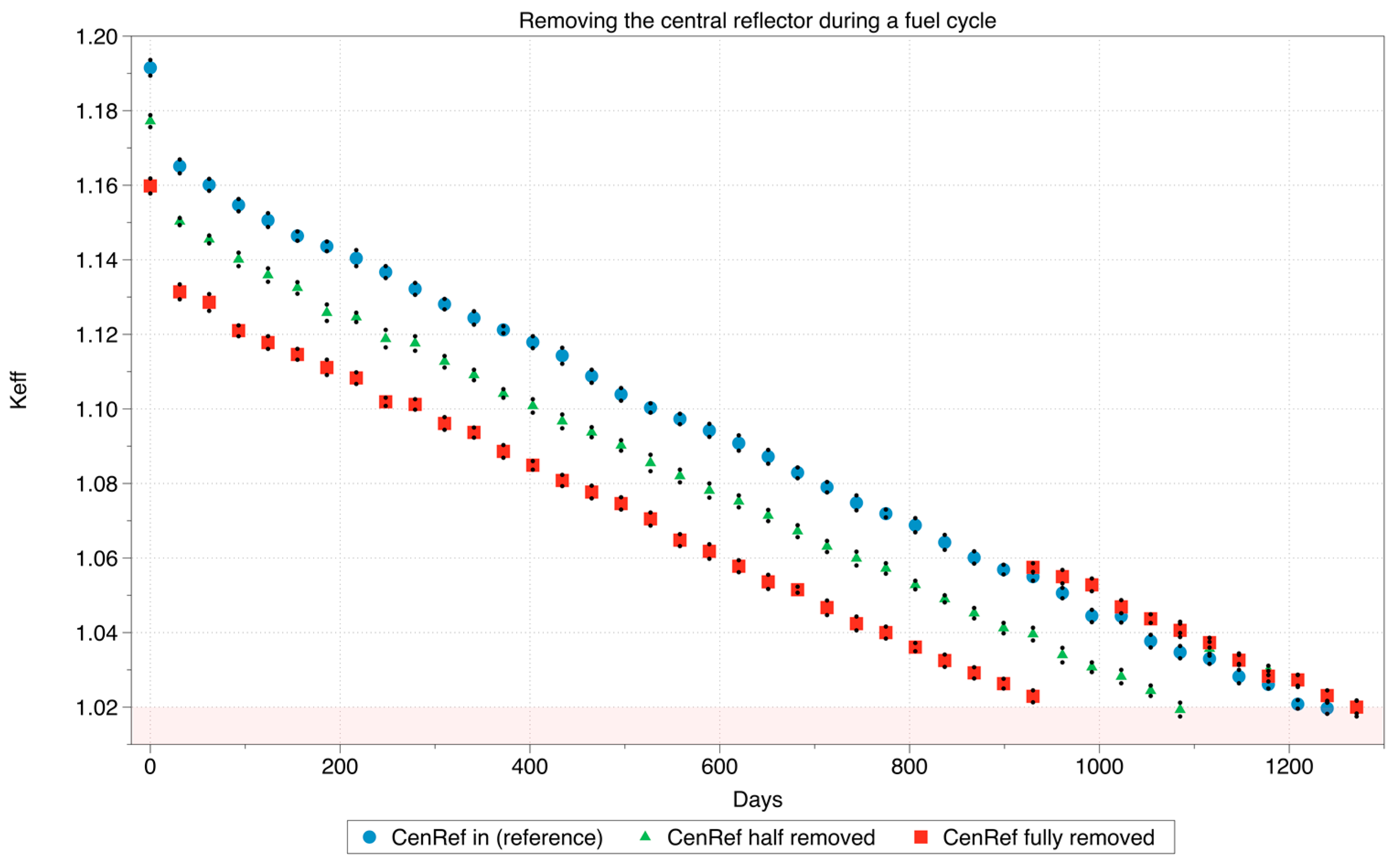
The initial test determines the overall criticality changes of the system over the period of the possible reactor operation. This experiment models the total criticality without poisons with the column in, out and half out. At the point in when the criticality is at 1.02, the column is reinserted to determine the overall lifetime achievable.
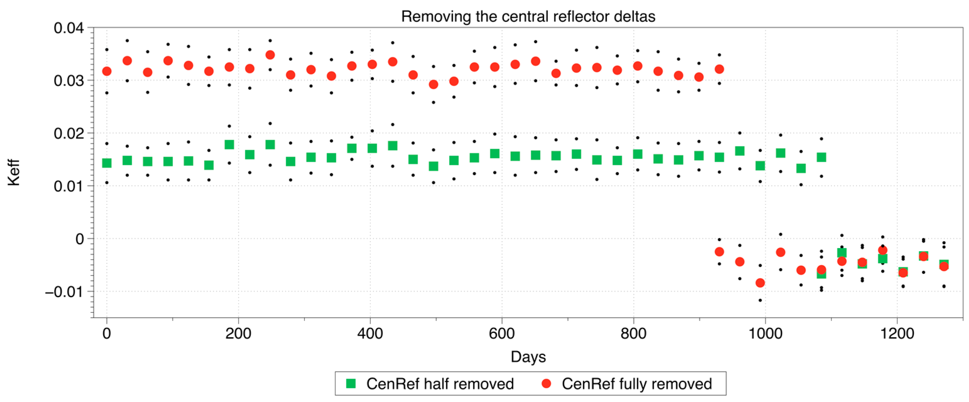
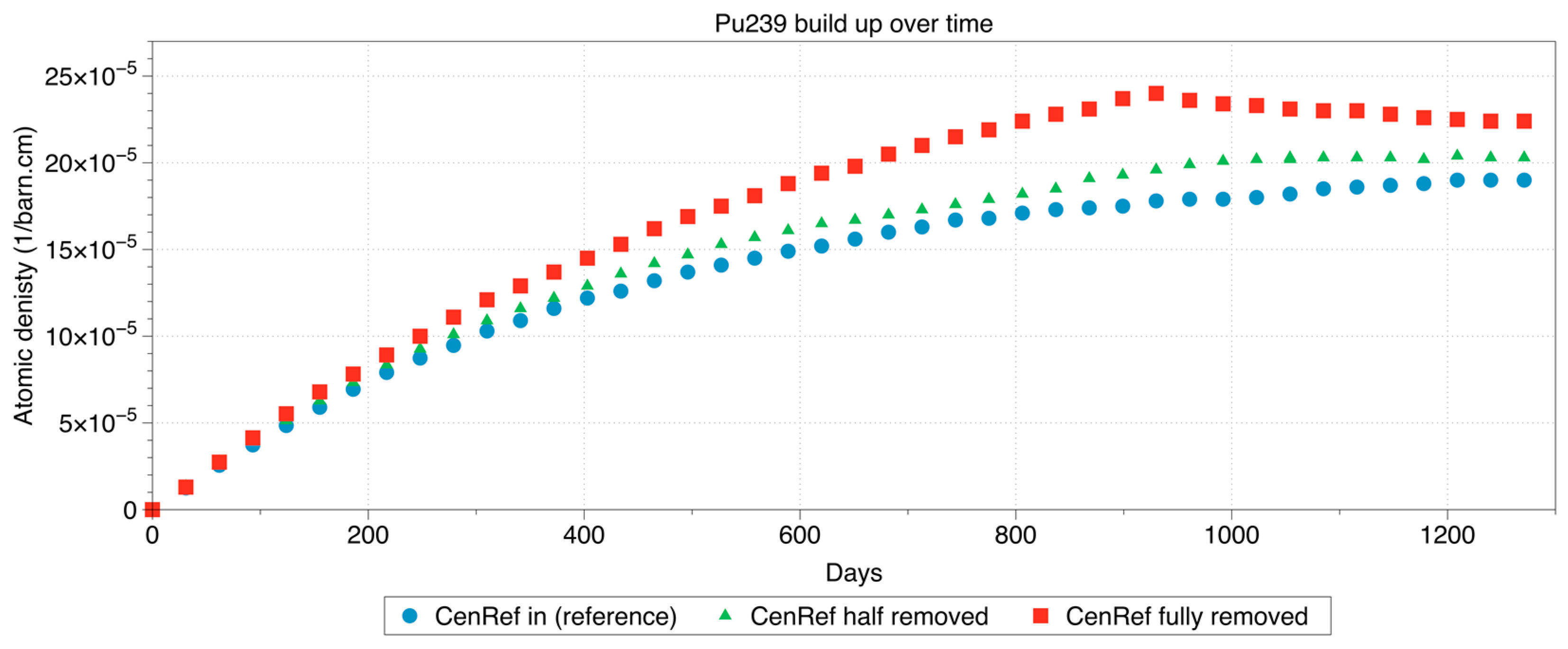
Figure 5 and Figure 6 show the initial criticality is dropped by 0.032 and 0.014 with the CenRef withdrawal at full and half, with respect to the base model. From the consideration of HTR operation, this is the point at which the reactivity control mechanism would have been activated to accommodate this criticality drop to limit the excess reactivity in the core. There is still a significant distance until reaching unity, which would have to be accommodated in a real design by a combination using FBPs and control rods. However, the applied method of withdrawal of a part of the CenRef has shown a clear drop-in criticality at initial start-up. At day 920 and 1085, the two withdrawn pieces of the central reflector must be reinserted into the centre to keep the criticality above the considered limit level of 1.02. Both models show after reinsertion of the central moderator a slightly higher criticality than the reference case.
The slightly increased criticality is likely due to an increased build-up on 239Pu as hypothesised earlier. This additional fissile material content allows a slight increase (~31) in full power days compared to the base model.
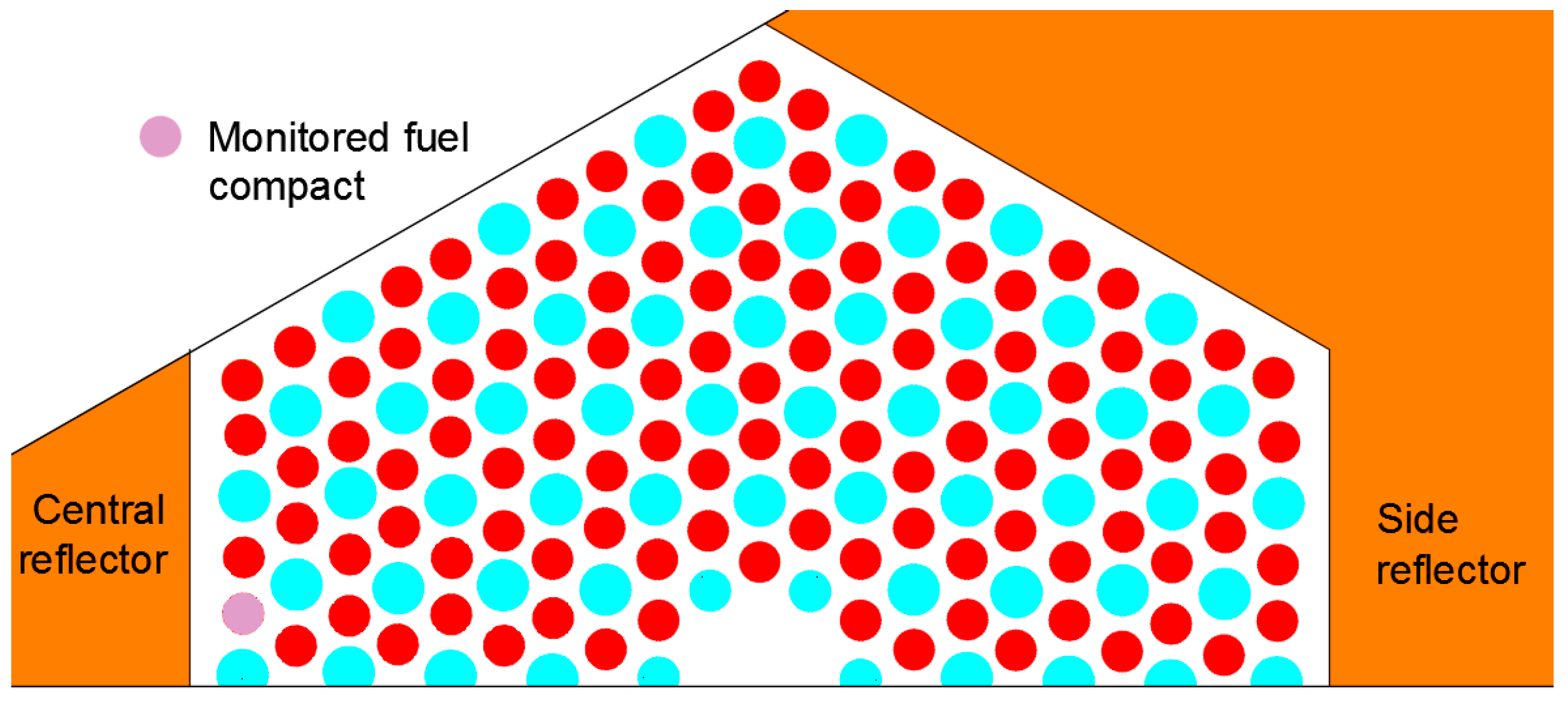
To analyse the 239Pu build up dependent on the position on the central moderator piece, a single 10 cm section at the centre of the axial fuel height was monitored to determine the overall 239Pu content over the burnup of the core. The fuel compact is identified in Figure 7.
At the beginning of the life of the core, there is zero content in 239Pu since 239Pu is not a content in UO2 fuel. Plutonium is bred time as neutrons are captured in the 238U atom which is transmuted via Neptunium into 239Pu. The development of the atomic densities of the 239Pu is recorded over burnup and compared between the three systems in Figure 8.
The positioning of the observed piece of fuel used to monitor the material composition is important as the system with half the reflector in is still partly benefitting from a large thermal spectrum across it since it is close to the upper surface of the movable moderator block. This is shown by the similarities to the base case in the system. When inserting the central reflector again, the half in system provided minimal variation due to the position. In the case of the fully removed central reflector, the re-insertion provides an immediate bend in the curve of the 239Pu concentration build up. Once the central reflector is re-inserted more 239Pu is consumed than new build. This is an effect of the higher capture cross section of 239Pu within the thermal energy range. This result reaffirms the conclusion that the additional criticality is granted from the breeding of additional fissile material and answers the hypothesis that the stored neutrons are capable of being re-deployed at a later stage.
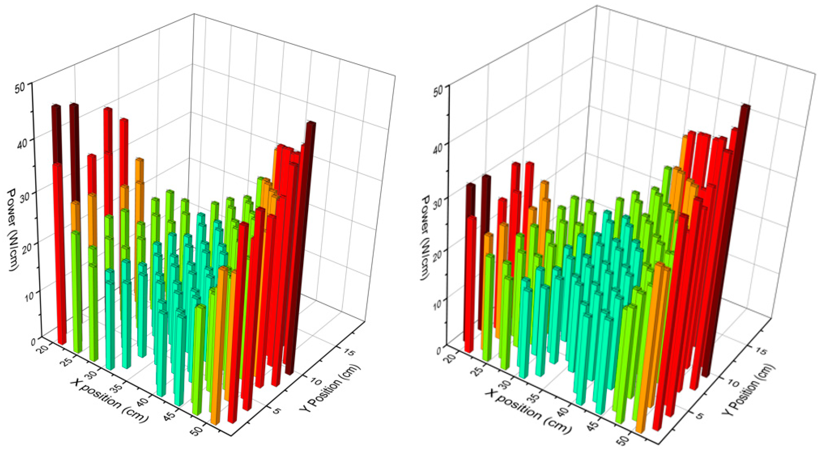
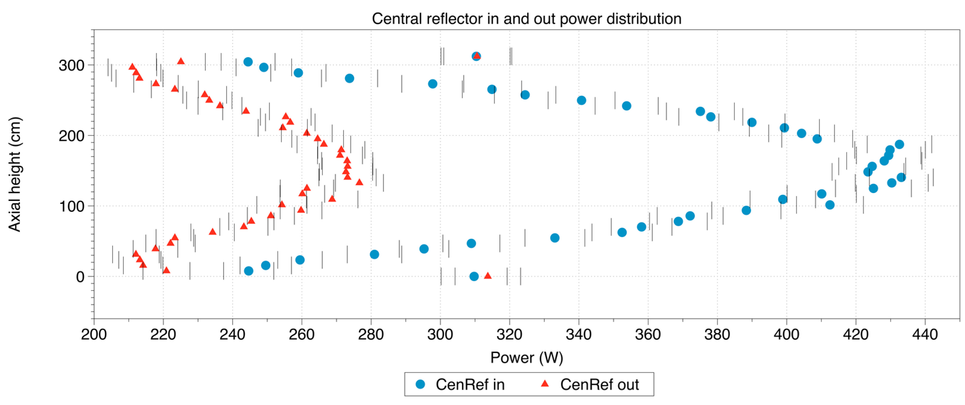
The second step is to investigate the power distribution in the compacts of the fuel assembly at the start-up of the reactor to see the effect of the absence of a major piece of the central reflector on the power distribution in the fuel assembly. The following figures represent the powers production in the fuel compacts based on the reaction rates across one half of the eastern fuel block with withdrawn moderator piece and the reference undisturbed case as shown in Figure 9.
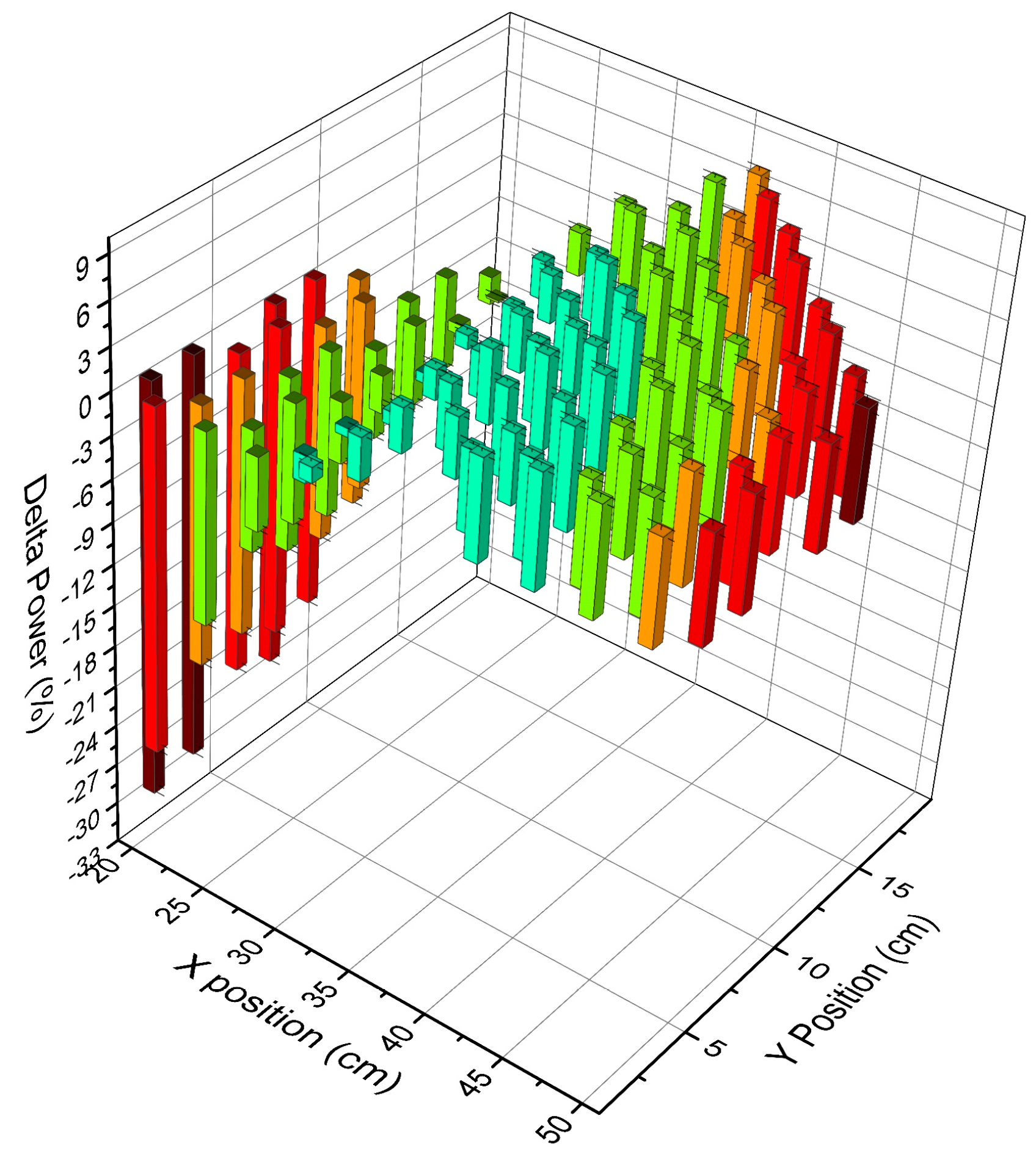
Both figures show a pronounced power distribution with a reduced power production in the centre of the fuel assembly and a clear increase of the power production in the compacts close to the central and the outer reflector. This characteristic power distribution in an HTR fuel block can be explained with the self-shielding of the fuel against the thermal neutron flux which is created in the pure moderator regions. Highly thermalized neutrons are created in the graphite reflector which has an extremely low absorption cross section for neutrons. As soon as the thermal neutrons are re-entering the fuel block, there is a high probability to cause fission reactions, thus the thermal neutrons have a low probability to reach the centre of the fuel assembly and cause fissions there. A close comparison of the power production in the innermost row of Figure 9 indicates that the removal of a part of the central moderator reduces the power production in the part of the fuel assembly close to the centre of the core. The detailed analysis of the deviation of the power production between the reference case and the case with extracted central moderator piece, given in Figure 10 shows a general power shift away from the centre of the core as a part of the moderator is removed. This is important due to the highest power pin being in the centre of the core which leads to a significant load reduction as the power is shifted across the core to the fuel pins close to the side reflector. In addition, the control of the reactivity must be assisted using burnable poisons and control rods. In most of the proposed fuel block designs for block type HTRs, the burnable poisons are in the corner compacts of the hexagons, since these are the positions which are exposed to the highest thermal neutron flux due to the location close to the reflectors while the control rods are in the side reflector.
Figure 10 emphasises the drop-in power on the central pins, with an overall power drop of ~30% during the full removal of the central reflector and a power increase of ~7.5% in the pins close to the side reflector.
Axial power distribution is shown in Figure 11 for the operational point just before and after the insertion of the central reflector piece. It is obvious that the total power is significantly reduced in the central pins. The removal of the central reflector completely changes the power production in the pin in Figure 7. Only the top and bottom of the pins produce identical power which could be explained by the effect of the axial reflectors.
5. Conclusions
This paper has briefly investigated a new type of reactivity control mechanism for a conceptually design SMR HTR. The concept touches on the ability to preserve some neutrons during high reactivity periods, for them to be utilised at a period later in the fuel cycle. This is achieved by breeding 239Pu at a higher rate than would be normally active in the fuel cycle by reducing the neutron moderation. This hypothesis was demonstrated that ~30% higher 239Pu production was witnessed at the point before the moderator is re-inserted. The 239Pu concentration depleted once the central reflector was reintroduced and this provided a large reactivity increase. This additional reactivity provided an increase of full power days of the reactor by approximately 31 days which corresponds to a 2.5% longer core lifecycle. It should be noted, that the present article demonstrates the concept of the moveable moderator reactivity control. The design of the moveable moderator can be further optimised, such as introducing the moveable moderator into the graphite reflector regions, concentric rings of graphite in the central reflector to allow for more precise reactivity control. The drawback comes with adding complexity into the control design, with the method demonstrated here focusing on the most simplistic method available.
The second test tried to identify any possible penalties with the fuel power loading within the core. In the case with the reflector removed, the overall power dropped by 30% within the highest loading pins which must be recognised as a positive effect. The power was shifted gradually across the core to the pins by the side reflector, which do not suffer from such high power as well as high burnups. Thus, we have identified a significant advantage when considering the power and resulting burnup distribution as the pins with the highest loading have had their power significantly reduced without the aid of neutron poisons.
In conclusion, the overall effect of changing the moderation within the centre of the core provides a two-fold benefit, initially with longer fuel life cycles and secondly with a better power distribution.
Author Contributions
S.A. implemented the system and performed the experiments. B.M. managed the project. D.L assisted with the idea development.
Funding
This project was funded through the Nuclear FiRST DTC through an ESPRC grant—EP/G037140/1.
Acknowledgments
The authors would like to acknowledge the assistance given by The University of Manchester IT Services, for the use of the Computational Shared Facility and professional support. The developers of the Serpent code for their continued support throughout the. For funding gratitude is owed to the ESPRC under the Nuclear First program—EP/G037140/1.
Appendix A
The original U-Battery report [9] stated that a five year fuel lifecycle could be achieved in the core configuration in Figure 2. The initial aims investigated replicating these results by using the data provided in the U-Battery manual, these values are represented in Table A1, Table A2 and Table A3.

Table A1.
Left: Radial dimensions and Right: Axial dimensions.
| Radial Dimensions | Axial Dimensions | ||||
|---|---|---|---|---|---|
| Part | Material | Radius (cm) | Part | Material | Height (cm) |
| Side reflector | BeO | 68 | Side reflector | BeO | 370 |
| Thermal insulation | SiC | 73 | Thermal insulation | SiC | 370 |
| Barrel | Steel | 75 | Barrel | Steel | 370 |
| Airgap | Helium | 80 | Airgap | Helium | 370 |
| RPV | Steel | 90 | RPV | Steel | 678.058 |
| Top helium | Helium | 183.158 | |||
| Bottom helium | Helium | 96.9 | |||
Table A2.
TRISO layers dimensions.
| TRISO Layers | Radius (cm) |
|---|---|
| Fuel | 0.025 |
| Buffer | 0.034 |
| PyCi | 0.038 |
| SiC | 0.0415 |
| PyCo | 0.0455 |
Table A3.
Material compositions.
| Part | Material | Composition | Mass Fraction | Temperature (k) | Density (g/cm3) |
|---|---|---|---|---|---|
| Side reflector | BeO | Be 9 | 0.360 | 873.15 | 2.8 |
| O 16 | 0.640 | ||||
| Thermal insulation | SiC | Si 28 | 0.500 | 973.5 | 3.2 |
| C 12 | 0.500 | ||||
| Barrel/RPV | Steel | Ni 58 | 0.107 | 673.5 | 8 |
| Ni 59 | 0.043 | ||||
| Ni 60 | 0.002 | ||||
| Cr 52 | 0.002 | ||||
| Mo 96 | 0.260 | ||||
| Fe 56 | 0.151 | ||||
| Si 28 | 0.076 | ||||
| Mn 55 | 0.149 | ||||
| C 12 | 0.032 | ||||
| P 31 | 0.084 | ||||
| S 32 | 0.171 | ||||
| Airgap/Top/Bottom Helium | Helium | H 4 | 1.000 | 600 | 0.002 |
| Fuel block/Central reflector | Carbon | C 12 | 1.000 | 973.15 | 1.8 |
| Fuel | UO2 | U235 | 0.176 | 1023.15 | 10.5 |
| U238 | 0.705 | ||||
| O 16 | 0.119 | ||||
| Buffer layer | Carbon | C 12 | 1.000 | 1023.15 | 1 |
| SiC layer | SiC | Si 28 | 0.500 | 1023.15 | 3.2 |
| C 12 | 0.500 | ||||
| Pyrolitic carbon inside | Carbon | C 12 | 1.000 | 1023.15 | 1.9 |
| Pyrolitic carbon outside | Carbon | C 12 | 1.000 | 1023.15 | 1.87 |
| Compact matrix | Carbon | C 12 | 1.000 | 1023.15 | 1.745 |
References
- UK GOV BAIS. UK Ratifies the Paris Agreement. Available online: https://www.gov.uk/government/news/uk-ratifies-the-paris-agreement (accessed on 15 May 2018).
- DECC. UK Renewable Energy Roadmap. Carbon N. Y. 2011, 5, 293–298. [Google Scholar]
- AEA. Pathways to 2050—Key Results. Available online: https://assets.publishing.service.gov.uk/government/uploads/system/uploads/attachment_data/file/48072/2290-pathways-to-2050-key-results.pdf (accessed on 24 May 2018).
- Department for Business, Energy & Industrial Strategy. Advanced Nuclear Technologies. Available online: https://www.gov.uk/government/publications/advanced-nuclear-technologies/advanced-nuclear-technologies (accessed on 11 May 2018).
- Grimston, M.; Nuttall, W.J.; Vaughan, G. The Siting of UK Nuclear Reactors. J. Radiol. Prot. 2014, 34, R1–R24. [Google Scholar] [CrossRef] [PubMed]
- NuScale. NuScale Power—UK Offering. Available online: http://www.nuscalepower.com/about-us/nuscale-power-in-uk/nuscales-uk-offering (accessed on 15 May 2018).
- Westinghouse. Westinghouse Proposes Joint SMR Development with UK. Available online: http://www.westinghousenuclear.com/uknuclear/About/News/View/Westinghouse-Proposes-Joint-SMR-Development-with-UK (accessed on 15 May 2018).
- Generation IV International Forum. Charter of the Generation IV International Forum. Available online: https://www.gen-4.org/gif/upload/docs/application/pdf/2016-07/charter_nov2006.pdf (accessed on 21 May 2018).
- Ding, M.; Kloosterman, J.L.; Kooijman, T.; Linssen, R. Design of a U-Battery®. Available online: http://www.janleenkloosterman.nl/reports/ubattery_final_201111.pdf (accessed on 11 May 2018).
- JAERI. Design of High Temperature Engineering Test Reactor (HTTR); JAERI: Tokyo, Japan, 1994.
- Reitsma, F.; Woods, P.; Fairclough, M.; Kim, Y.; Tulsidas, H.; Lopez, L.; Zheng, Y.; Hussein, A.; Brinkmann, G.; Haneklaus, N.; et al. On the Sustainability and Progress of Energy Neutral Mineral Processing. Sustainability 2018, 10, 235. [Google Scholar] [CrossRef]
- Elder, R.; Allen, R. Nuclear Heat for Hydrogen Production: Coupling a Very High/High Temperature Reactor to a Hydrogen Production Plant. Prog. Nucl. Energy 2009, 51, 500–525. [Google Scholar] [CrossRef]
- Science Alert. China Says It’ll Have a Meltdown-Proof Nuclear Reactor Ready by Next Year. Available online: https://www.sciencealert.com/china-says-it-ll-have-a-meltdown-proof-nuclear-reactor-ready-by-next-year (accessed on 15 May 2018).
- Lohnert, G.H.; Reutler, H. The Modular HTR—A New Design of High-Temperature Pebble-Bed Reactor. Nucl. Energy 1983, 22, 197–200. [Google Scholar]
- IAEA. High Temperature Gas Cooled Reactor Fuels and Materials. Available online: https://www-pub.iaea.org/MTCD/Publications/PDF/TE_1645_CD/PDF/TECDOC_1645.pdf (accessed on 21 May 2018).
- Zhang, Z.; Dong, Y.; Li, F.; Zhang, Z.; Wang, H.; Huang, X.; Li, H.; Liu, B.; Wu, X.; Wang, H.; et al. The Shandong Shidao Bay 200 MWe High-Temperature Gas-Cooled Reactor Pebble-Bed Module (HTR-PM) Demonstration Power Plant: An Engineering and Technological Innovation. Engineering 2016, 2, 112–118. [Google Scholar] [CrossRef]
- Bess, J.D.; Dolphin, B.H. Evaluation of the Start-Up Core Physics Tests at Japan’ s High Temperature Engineering Test Reactor. Available online: https://inldigitallibrary.inl.gov/sites/sti/sti/4460716.pdf (accessed on 12 May 2018).
- Atkinson, S.; Abram, T.J.; Litskevich, D.B.M. A Comparison between Beryllium Oxide and Nuclear Graphite in a Small Scale High Temperature Reactor. Unpublished work. 2018. [Google Scholar]
- IAEA. Boiling Water Reactor Simulator with Passive Safety Systems User Manual. Available online: https://www.iaea.org/NuclearPower/Downloads/Simulators/Advanced.BWR.Manual.2009-10.pdf (accessed on 21 May 2018).
- Heijna, M.C.R.; de Groot, S.; Vreeling, J.A. Comparison of Irradiation Behaviour of HTR Graphite Grades. J. Nucl. Mater. 2017, 492, 148–156. [Google Scholar] [CrossRef]
- Snead, L.L.; Contescu, C.I.; Byun, T.S.; Porter, W. Thermophysical Property and Pore Structure Evolution in Stressed and Non-Stressed Neutron Irradiated IG-110 Nuclear Graphite. J. Nucl. Mater. 2016, 476, 102–109. [Google Scholar] [CrossRef]
- IAEA. Design of the Reactor Core for Nuclear Power Plants—Safety G. Available online: https://www-pub.iaea.org/MTCD/publications/PDF/Pub1221_web.pdf (accessed on 15 May 2018).
- Leppänen, J.; Pusa, M.; Viitanen, T.; Valtavirta, V.; Kaltiaisenaho, T. The Serpent Monte Carlo Code: Status, Development and Applications in 2013. Ann. Nucl. Energy 2015, 82, 142–150. [Google Scholar] [CrossRef]
- Maria, P. Higher-Order Chebyshev Rational Approximation Method and Application to Burnup Equations. Nucl. Sci. Eng. 2016, 182, 297–318. [Google Scholar] [CrossRef]
Figure 1.
Reactivity control in the HTTR.

Figure 2.
The original (left) and the modified graphite (right) U-Battery design used in this report.
Figure 2.
The original (left) and the modified graphite (right) U-Battery design used in this report.

Figure 3.
Central reflector removed in the centre of the core and replaced with helium coolant.

Figure 4.
Serpent model of modified U-Battery with the central reflector removed.

Figure 5.
Criticality with CenRef column at varying positions, with criticality 1.02 marked.

Figure 6.
Delta from base of CenRef removal (Reference—Half removed) & (Reference—Fully removed).

Figure 7.
Compact monitored for the 239Pu build up analysis.

Figure 8.
239Pu build up over time with the different central reflector arrangements in the monitored central pin.
Figure 8.
239Pu build up over time with the different central reflector arrangements in the monitored central pin.

Figure 9.
(Left) Power distribution with the central reflector fully inserted (undisturbed reference case); (Right) Power distribution with the central reflector fully removed.
Figure 9.
(Left) Power distribution with the central reflector fully inserted (undisturbed reference case); (Right) Power distribution with the central reflector fully removed.

Figure 10.
The change in power (Central reflector out- central reflector in).

Figure 11.
Axial power distribution in the monitored central pin.

Table 1.
CenRef positions considered.
| Central Reflector Position | Height of Central Reflector (m) |
|---|---|
| Fully inserted | 3.2 |
| Half inserted | 1.6 |
| Removed | 0 |
© 2018 by the authors. Licensee MDPI, Basel, Switzerland. This article is an open access article distributed under the terms and conditions of the Creative Commons Attribution (CC BY) license (http://creativecommons.org/licenses/by/4.0/).
Share and Cite
MDPI and ACS Style
Atkinson, S.; Litskevich, D.; Merk, B. Variable Reactivity Control in Small Modular High Temperature Reactors Using Moderation Manipulation Techniques. Energies 2018, 11, 1897. https://doi.org/10.3390/en11071897
AMA Style
Atkinson S, Litskevich D, Merk B. Variable Reactivity Control in Small Modular High Temperature Reactors Using Moderation Manipulation Techniques. Energies. 2018; 11(7):1897. https://doi.org/10.3390/en11071897
Chicago/Turabian StyleAtkinson, Seddon, Dzianis Litskevich, and Bruno Merk. 2018. "Variable Reactivity Control in Small Modular High Temperature Reactors Using Moderation Manipulation Techniques" Energies 11, no. 7: 1897. https://doi.org/10.3390/en11071897
Note that from the first issue of 2016, this journal uses article numbers instead of page numbers. See further details here.