An Experimental Study on Flame Puffing of a Swirl Partially Premixed Combustion under Varying Mass Flow Rate of Primary Air


National Thermal Power Engineering & Technology Research Center, North China Electric Power University, Beijing 102206, China
*
Author to whom correspondence should be addressed.
Energies 2018, 11(7), 1916; https://doi.org/10.3390/en11071916
Submission received: 10 July 2018
/
Revised: 19 July 2018
/
Accepted: 20 July 2018
/
Published: 23 July 2018
(This article belongs to the Section I: Energy Fundamentals and Conversion)
Abstract
:It is of practical significance to understand the flame puffing behavior under varying mass flow rate of primary air ṁpri. An experiment was conducted to study the impact of ṁpri on flame puffing in a swirl partially premixed combustor, the puffing behavior of six significant flame properties was examined. The results showed that almost every spectrum had two fundamental frequencies, which is different from the single-peak spectrum of non-swirl flame. The flame heat-release rate, flame area, and flame equivalent width had identical dominant frequency and sub-dominant frequency, both decreased with the increasing of ṁpri. It was attributed to the decreased overall flame temperature caused by the improved mixing of fuel and primary air. All measured frequencies were in the range of 3–14 Hz, but the predicted frequencies from the theoretical models based on non-swirl flame were larger than the measured. This indicates the puffing frequency of swirl flame was much more sensitive to the variation in ṁpri than the frequency of non-swirl flame. Moreover, the amplitude of flame length was the smallest in all properties, with the most weakened oscillating intensity. While the amplitude of the flame area and flame equivalent width were the largest, with the strongest oscillation level. Consequently, the flame puffing is mainly attributed to the oscillation in width direction.
1. Introduction
Observation of many combustion processes shows that the state of flame is not stationary at any moment, it displays a substantial oscillating characteristic which is generally termed as ‘flame puffing’, ‘flame flickering’, or ‘flame pulsation’ [1]. Flame puffing is a consequence of the interaction between the flame surface and large vortices, these vortices are formed due to the buoyant force, and they move downstream along the flame front thus inducing flame oscillation [2]. With the existence of flame puffing, the structure of the flame is always changed with time, which influences some important combustion properties, e.g., the entrainment velocity of oxidizer into the flame, flame radiation, flame size, and the efficiency of combustion. With severe conditions, the puffing even can cause flame extinction and the failure of combustion instruments [3]. So it is of practical significance to understand flame puffing behavior in the fields of combustion instability and flame monitoring.
In recent decades, the characteristics of flame puffing have been explored in many researches. Bahadori et al. [4] and Durox et al. [5] investigated the effects of gravitational level on flame flickering respectively; they found that the flickering frequency f has a proportional relationship with gn (g is gravitational acceleration), the exponent n is 0.5 from the former, while n is 0.67 from the latter. Arai et al. [6] assumed that the increase of flickering frequency at higher gravity levels is due to a decrease in the wavelength and increase in the wave velocity. Some investigators discovered that the frequency scales with diameter of the injector nozzle dj as f = Cdj−0.5 [1,7,8,9,10], in which C is constant but different among varying studies. Yilmaz et al. [11] used Particle Image Velocimetry (PIV) to investigate oscillation of the flow field in a diffusion flame, they observed that the flame oscillation intensifies when the fuel flow rate lowers.
To obtain the puffing signal, Pan at al. [2] used a photomultiplier (PMT) coupled with a filter (430 ± 10 nm) for measurement of the unsteady heat-release rate of flame. It was revealed that the pulsation frequency progressively became higher under increasing flow velocity of annular air. This method of employing a dynamic heat-release rate to examine flame puffing behavior can also be seen in Li et al. [12]. Fang et al. [13] obtained the puffing frequency under sub-atmospheric pressure by recording the fluctuation of the visible flame area. The results showed that the frequency declines with the increase of pressure. Yilmaz et al. [14] measured the changes in flame light emission. They found that the frequency exhibits a nonmonotonic relationship with the flow rate of fuel. Pretrel and Audouin [15] investigated the flickering instabilities in a confined compartment by observing the variation of flame length and width with time. They pointed out that the flickering frequency in a confined environment has a lower value than that in an open atmosphere. Cetegen and Dong [16] analyzed the puffing behavior by measuring the fluctuations of total pressure induced by the velocity oscillations with a differential pressure transducer. Moreover, Chen et al. [17] proposed an image processing method base on image correlation to obtain the flickering frequency. Tang et al. [18] used this method to examine the pulsation frequency for a rectangular nozzle. It was concluded that the frequency enlarges with the increase in nozzle aspect ratio.
Turbulent partially premixed combustion has widespread application in many industrial devices, such as Bunsen burners, staged combustors, gas-fired furnaces, and gas turbine combustors. The partially premixed flame is produced when the fuel containing a sub-stoichiometric volume of air (usually stated as primary air) come across a flame front and burns with an oxidizer/secondary air (initially separated) [19]. The reason for choosing a partially premixed flame is mainly its high stability. Moreover, its flame size can be controlled in comparison with diffusion flame. Numerous experimental and numerical investigations of partially premixed flame have previously been reported [19,20,21,22,23,24,25,26,27], e.g., studies on flame structure, flame radiation, and pollutants emissions; some researches also include the effects of primary air’s amount on combustion properties. However, little work has been performed to explore the influence of primary air’s amount on flame puffing of partially premixed combustion.
In the present investigation, we continued to explore the puffing behavior on the basis of our previous work [28], which briefly reported the oscillation of one flame property (flame heat-release rate) under four kinds of operating conditions (mass flow rate of fuel, combustor pressure, mass flow rate of primary air, and exit velocity of injector). While in this paper, we thoroughly analyzed the in-depth oscillation information of six significant flame properties under the mass flow rate of primary air by conducting an experiment. The flame properties include flame heat-release rate H, flame area A, flame length L, flame equivalent width W, flame center length Lc, and image correlation coefficient R (these properties will be defined in the following section). Firstly, the puffing dynamics were analyzed; afterward, the puffing frequency was determined and compared with the predicted values; lastly, the time-mean value of the flame properties was obtained, and the puffing amplitude normalized by the time-mean value was explored. This study exerts an effort to provide information for understanding the puffing behavior of a swirl flame under varying mass flow rates of primary air.
2. Experimental Setup and Methods
2.1. Experimental Apparatus
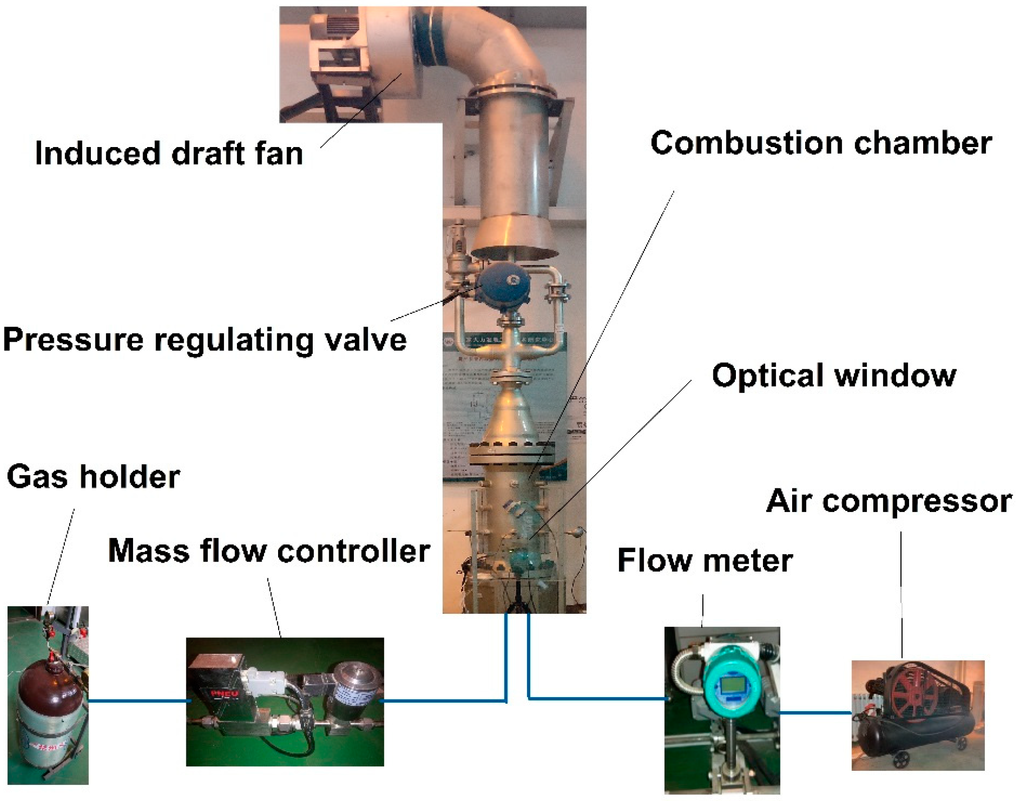
These combustion tests were conducted on a 20 kW design power facility which can investigate high pressure combustion [28]. This test rig has three main sections, as displayed in Figure 1.
- (1)
- First of all, there is a supply section which comprises of several parts including an air compressor, mass flow rate controller (MFC), and a high-pressure gas holder. The air compressor provides the air for combustion with a maximum capacity of 2.5 kg/min. The flow rate of air is measured by a flow meter while air flow is regulated by an electronic control valve. An MFC, having a maximum capacity of 36 g/min, was installed after the gas holder measures and controls fuel (methane) flow rate.
- (2)
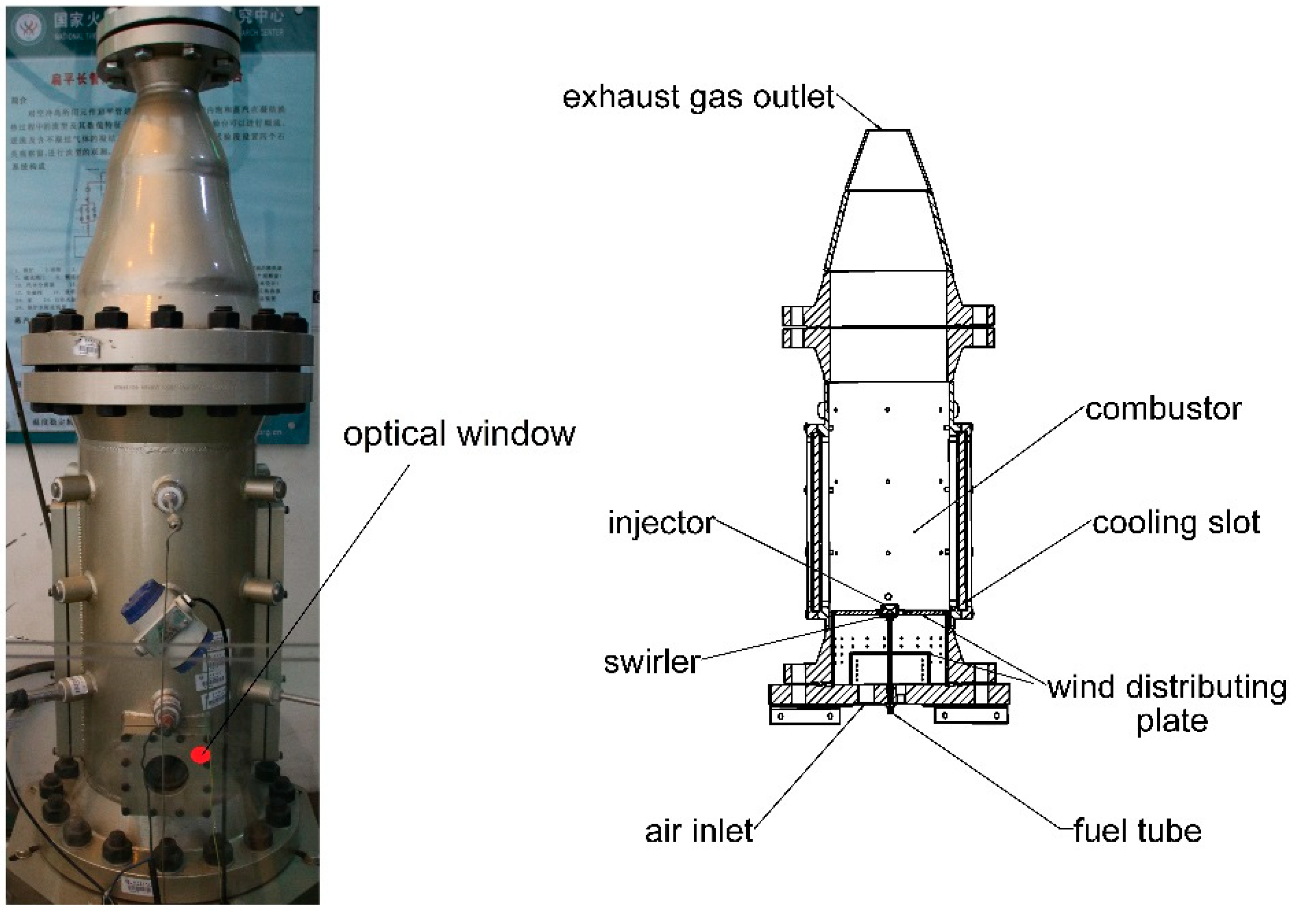
- The second section of this facility is the combustion section which contains an axisymmetric cylindrical chamber (combustor) and a swirl burner, as shown in Figure 2 and Figure 3. The length of the combustor is 1.35 m and the diameter is 0.3 m. Figure 3 illustrates the swirl burner that contains a radial swirler which improves the fuel/air mixing quality. Ten straight vanes having setting angle α of 50° constitute the swirler. To enhance flame stability, a convergent divergent nozzle was designed, having an angle of 42° between its divergent side face and vertical line. Primary air, which is a fraction of main air, flows tangentially through the swirler where fuel is delivered by the central fuel. Primary air carrying fuel then enters into the combustion chamber where the combustion process takes place. Flame length is controlled by primary air which mixes with fuel before combustion and is only 5% (on mass basis) of the total air supplied by the compressor. The mixing quality of primary air and methane is still insufficient because this mixing process occurs in a shorter distance. The remaining fraction of air/secondary air flows through a wind distributing plate and then from an annular slot it enters the combustor flowing adjacent to the inner walls. Secondary air not only supports combustion but also cools down the wall and metallic parts to avert damages caused by overheating. On the combustor wall an optically accessible window is attached for monitoring and recording the flame structure.
- (3)
- Lastly, there is an exhaust section which draws exhaust gas out into the atmosphere with the help of an induced draught system. It also includes a device to control the operating pressure of the combustor and is termed as the pressure regulating valve.
2.2. Measurement Methods
To examine the dynamic behavior of flame, the flame zone was detected by recording the chemiluminescence image of the CO2* species. For this purpose, a high-speed COMS (Complementary Metal Oxide Semiconductor) camera named Olympus i speed 3 (Olympus, Essex, UK) was installed near the optical window and a band filter BG 38 (HB-OPTICAL, Shengyang, China) with a bandwidth of 340–600 nm was attached to the camera.
Samaniego et al. [29] reviewed the CO2* chemiluminescence method which is often employed for determination of the flame zone. Although several species like CH, OH, and PAH may exist within the range of the 340–600 nm wavelength, their impact is trivial and can be ignored as CO2* is the prime emitter for hydrocarbon flames. As suggested in the review [29], more than 95% of chemiluminescence comprises CO2* emission when integrated over the 340–600 nm range. Thus from the whole 340–600 nm wavelength range, chemiluminescence can be captured and construed as CO2* emission. CO2* is produced in three fundamental steps as given in Equation (1) [29] and it indicates the reaction zone.
In the first step of the reaction CO2* is produced, while in the second step CO2* emits light and returns to its ground state (CO2), where M is a kind of intermediate product of combustion. The final stage of the reaction is a quenching step which contends with the second step of the reaction. In this stage, CO2* returns to its ground state, as it can be seen in Equation (1).
2.3. Flame Properties
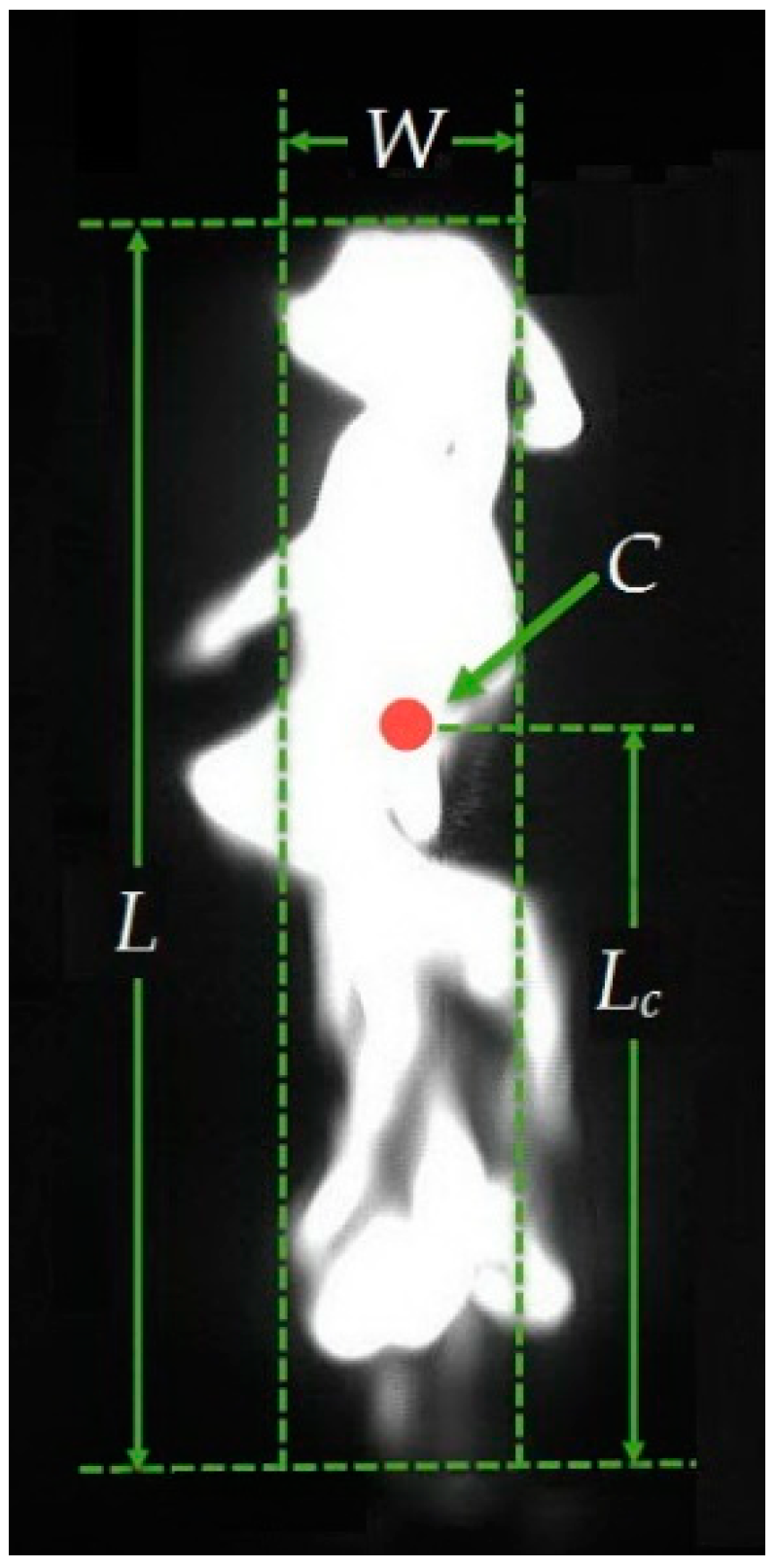
The measured flame zone based on the method of CO2* chemiluminescence is used to obtain the flame properties. We examined the flame properties under varying the mass flow rate of primary air (i.e., ṁpri = 95 g/min, 100 g/min, 105 g/min) while the fuel’s mass flow rate remained constant (16 g/min). These flame properties include flame heat-release rate H, flame area A, flame length L, flame equivalent width W, flame center length Lc, and image correlation coefficient R. Some of them are shown in Figure 4; all properties are determined as follows:
- (1)
- Flame heat-release rate H is usually determined by integrating the intensity of the chemiluminescence over the entire image, i.e., summing the gray values of all pixels in that image [30,31,32]. The gray value is a parameter which reflects the luminosity of a grayscale image, and it has a range of 0–255. The luminance enhances gradually from 0 to 255 where 0 corresponds to black color while 255 corresponds to a white color (note that Figure 4 is a little saturated, which may have influence on the determination of H). While it is not the Figure we employed to obtain the signal in the paper, we used it to clearly present flame geometric properties because it is bright. The Figures corresponding to the cases we explored in the present work are not saturated, and the relevant heat-release rate signal was found to have a significant and regular variation with time, so it can be a qualitative indicator of flame oscillation.
- (2)
- Flame area A is obtained by calculating the amount of all luminous pixels, whose gray value is larger than a threshold. After comparing various results based on different thresholds, we choose 100 as the threshold in the present calculation, which is enough to determine the flame area accurately.
- (3)
- Flame length L is defined as the distance between the injector exit and the flame tip. It is obtained by calculating the number of pixels from the nozzle exit to the flame tip (the visual tip of the flame).
- (4)
- Flame equivalent width W is defined as the flame average diameter and it is calculated as the ratio between flame area A and flame length L [33], namely W = A/L.
- (5)
- Flame center C is employed to intensively describe flame position by considering the flame as a point [31,34,35] (displayed as a red point in Figure 5), it is determined by employing the gravity center concept which is calculated by treating each pixel as a local position and considering each individual pixel’s intensity as its mass. In this way, the flame center can be obtained. Distance from the nozzle exit to the flame center is known as flame center length Lc, and it is used to indicate flame position.
- (6)
- The image correlation coefficient, R, is employed to determine the degree of correlation between two images and its value ranges from 0 to 1. The increment of R indicates that both images are increasingly correlated, R = 0 indicates both images have no correlation, while R = 1 indicates both images are identical. This technique is widely used in fields such as image compression, image matching, and image retrieval. By choosing one of the continuous frames obtained from the video as a base image and then calculating the R between the base image and each image in the sequence, a sequence of R is obtained and is regarded as the puffing signal. A grayscale digital image can be described by a matrix M (m, n), where m stands for the number of vertical pixels and n stands for the number of horizontal pixels. A total of m × n pixel units constitute the M, and the value of each pixel unit is the gray value. The calculation of R between image A (m, n) and image B (m, n) is done by using Equation (2)where A and B are the average values of A and B respectively.
3. Results and Discussion
3.1. Puffing Dynamics
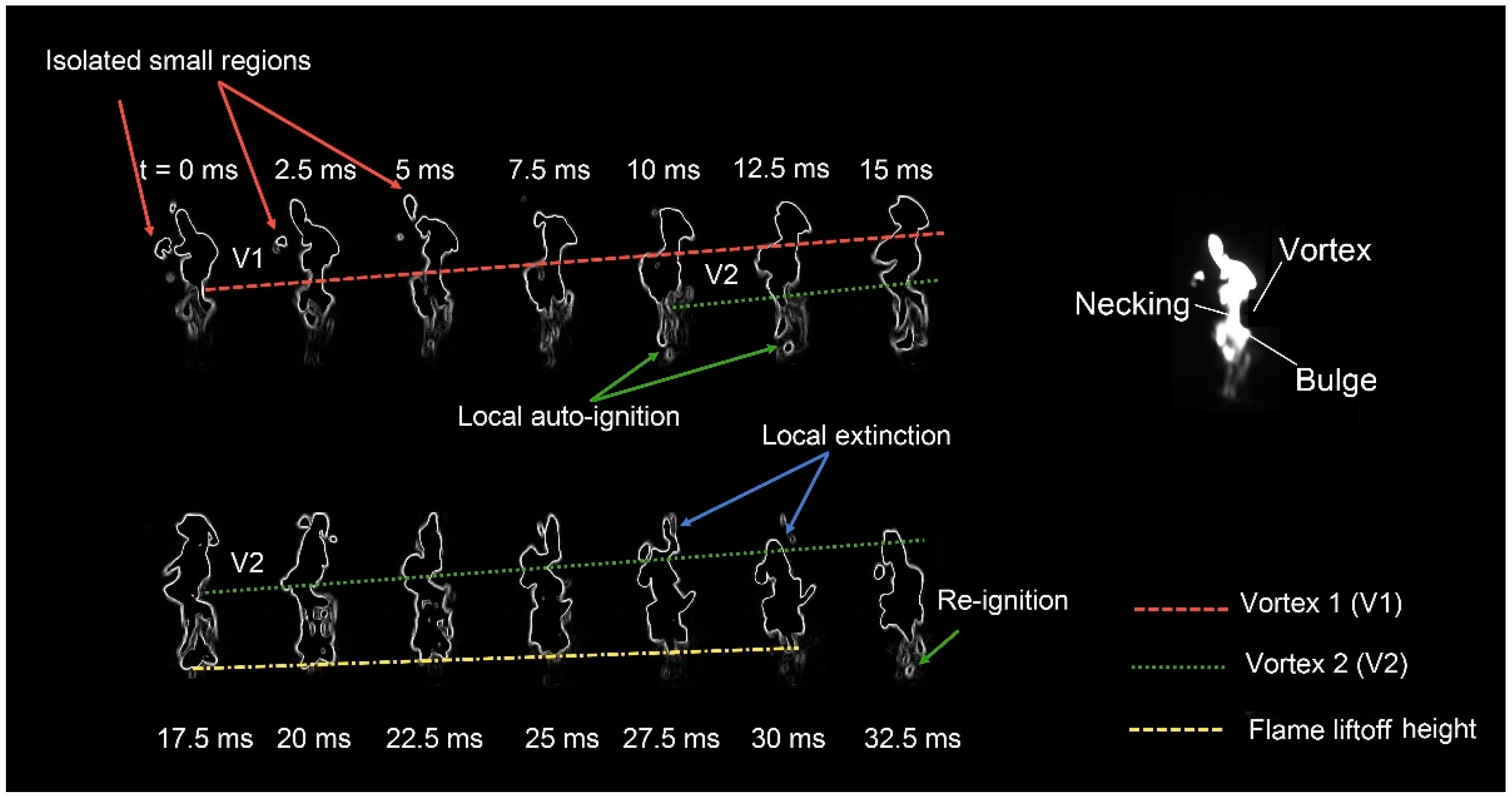
The flame zone was recorded in time sequence, with a recording frame rate of 400 frames per second (fps). Under this rate, the interval time between two sequential frames is 2.5 ms. The image has a resolution of 1280 H × 1024 V pixels. To analyze the flame dynamics, a sequence of continuous flame surface topography of the flame zone is displayed in Figure 5 [28]. It can be noticed that the flame surface is wrinkled because of the effect of large vortices around the flame front, these vortices are generated due to the buoyant force caused by combustion. During the combustion, high-temperature gas is produced in the flame zone and accelerated into the cool ambient air. As the flow velocity of heated gas is larger than that of surrounding air, a vortex V1 outside the flame surface is formed at 0 ms, which facilitates the entrainment of air into the flame. As V1 moves upward along the flame front, a characteristic necking is observed. At the same time, a low-pressure region behind V1 is created and immediately filled by the burning gas from upstream, resulting in the production of a bulge. When this bulge rises, another vortex V2 is generated below the bulge at 10 ms; it convects as V1. The movement of vortices causes the flame puffing.
In addition, we also observed some attractive phenomena during the puffing process, which can give more insights to understand the puffing. At 10 ms, the flame base appeared a local auto-ignition, which caused a processive increase in the burning zone at the flame root in succedent images from 10 ms to 17.5 ms. Subsequently, the flame base is lifted off downstream from 17.5 ms to 30 ms, during which time, the liftoff height slightly became higher. Afterward, at 32.5 ms, a local re-ignition was found at the flame root. Which indicates that the behavior of auto-ignition and liftoff around the flame base alternately occur during the process of flame puffing. Another noticeable phenomenon is the flame extinction which appears at flame tip, as shown at 30 ms. This is attributed to the excessive air entrainment toward the flame tip due to the movement of the vortex, and thus the local temperature dropped significantly to extinguish the flame tip. It leads to a sudden shortening of the flame length. Moreover, some isolated small flame regions were found which are cut off from the main body by the entrained air, as displayed in 0–5 ms. These segmental regions also play an important indispensable role in the pulsation of flame.
3.2. Puffing Signal and Spectrum
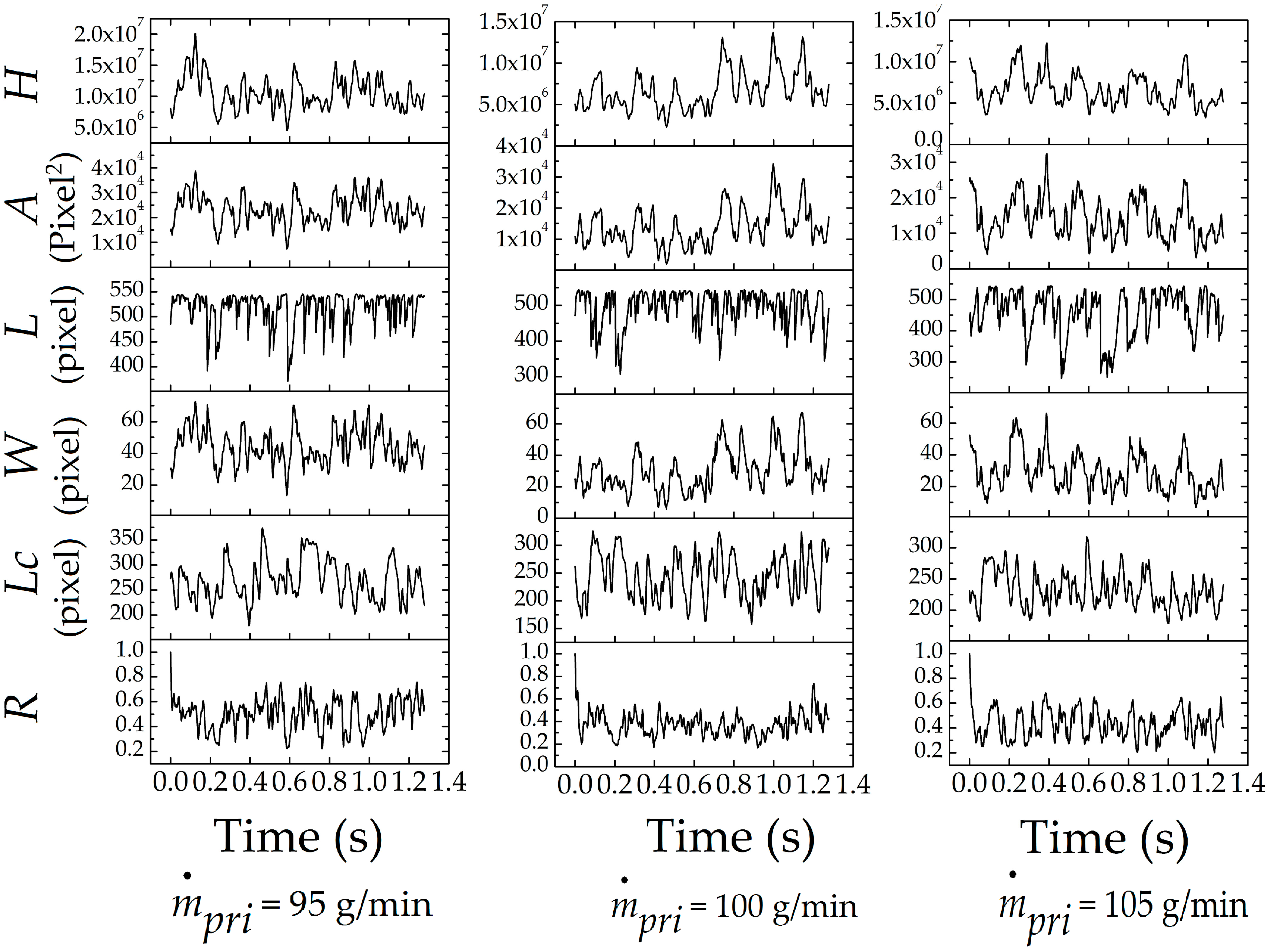
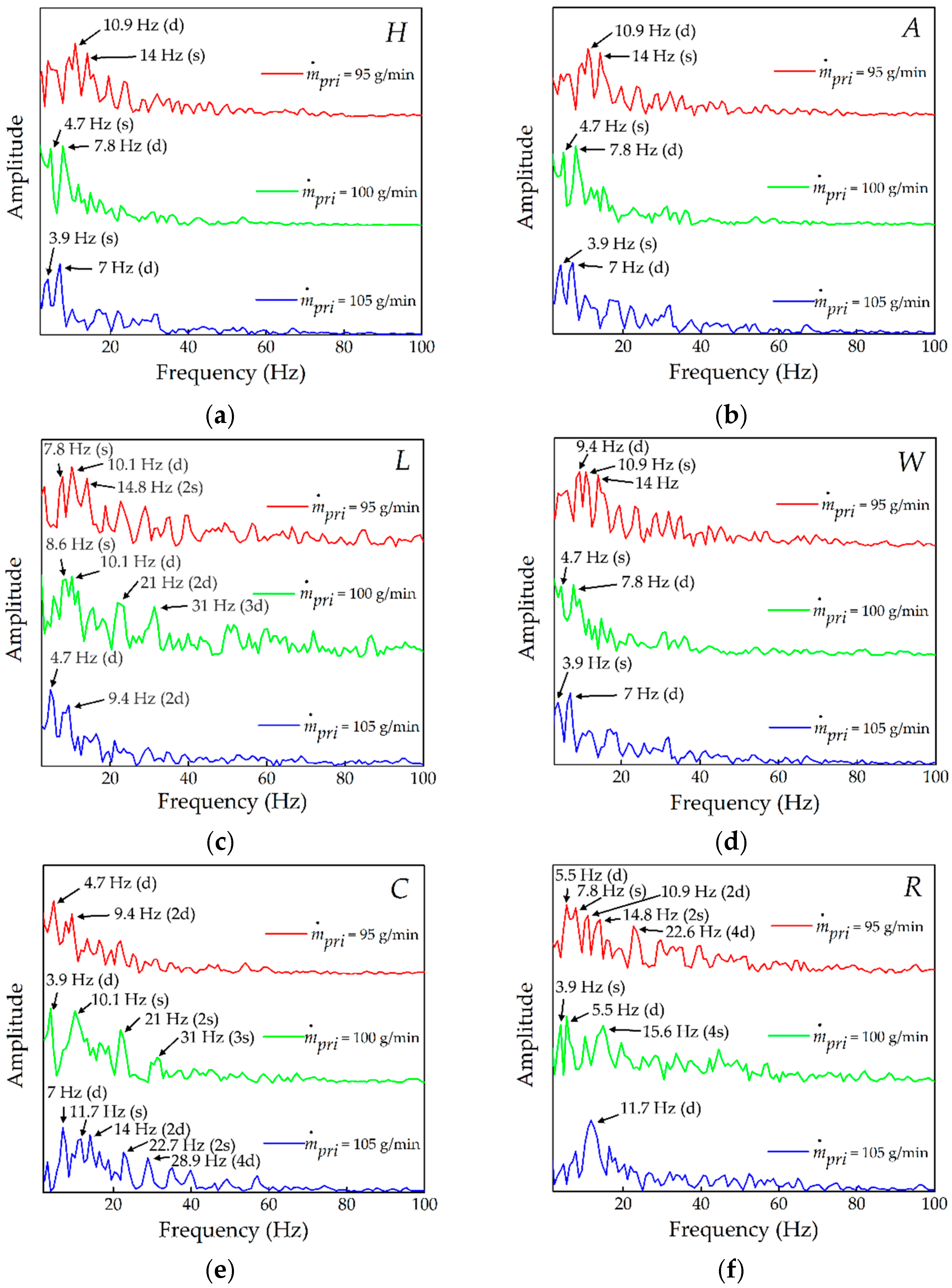
The time variation in flame properties is displayed in Figure 6. For each case, the length of time is 1.28 s, a total of 512 sequential images were analyzed. The signal of flame heat-release rate was from our previous research [28]. It was seen that the curves of flame heat-release rate, flame area, and flame equivalent width are almost the same for any case, which indicates the flame heat-release rate is proportional to flame area and flame equivalent width. While, other properties including flame length, flame center length, and correlation coefficient display different varying behaviors with time. These signals were processed by Fast Fourier Transform (FFT) to obtain the characteristic frequency of flame puffing. Their amplitude-frequency curves are shown in Figure 7.
In Figure 7, almost every spectrum has several oscillation frequencies with a certain amount of amplitude. This is different with the amplitude-frequency characteristics of non-swirl flame, which always has a single-peak spectrum as can be found in previous researches [1,3]. The appearance of multiple frequencies for present swirl flame may be due to the occurrence of spiral flow field (e.g., the precessing vortex core (PVC)), which leads to the complex flame oscillation behavior. All the frequencies exist in a low-frequency range, mainly in 0–50 Hz. Nearly each spectrum has two fundamental frequencies: dominant frequency (denoted as d) and sub-dominant frequency (denoted as s). Other frequencies in the same spectrum are found to be their harmonic frequencies (denoted as 2d, 3d, 4d; or 2s, 3s, 4s). For example, 2d represents the second order harmonic frequency of the dominant frequency (d); while 2s represents the second order harmonic frequency of the sub-dominant frequency (s). As the fundamental frequencies (dominant frequency (d) and sub-dominant frequency (s)) in each case are the primary ones, we choose them for each condition to investigate the frequency behavior with the varying mass flow rate of primary air. Note that there are three spectrums which do not have the sub-dominant frequency, their corresponding conditions are ṁpri = 105 g/min in Figure 7c, ṁpri = 95 g/min in Figure 7e and ṁpri = 105 g/min in Figure 7f.
3.3. Puffing Frequency
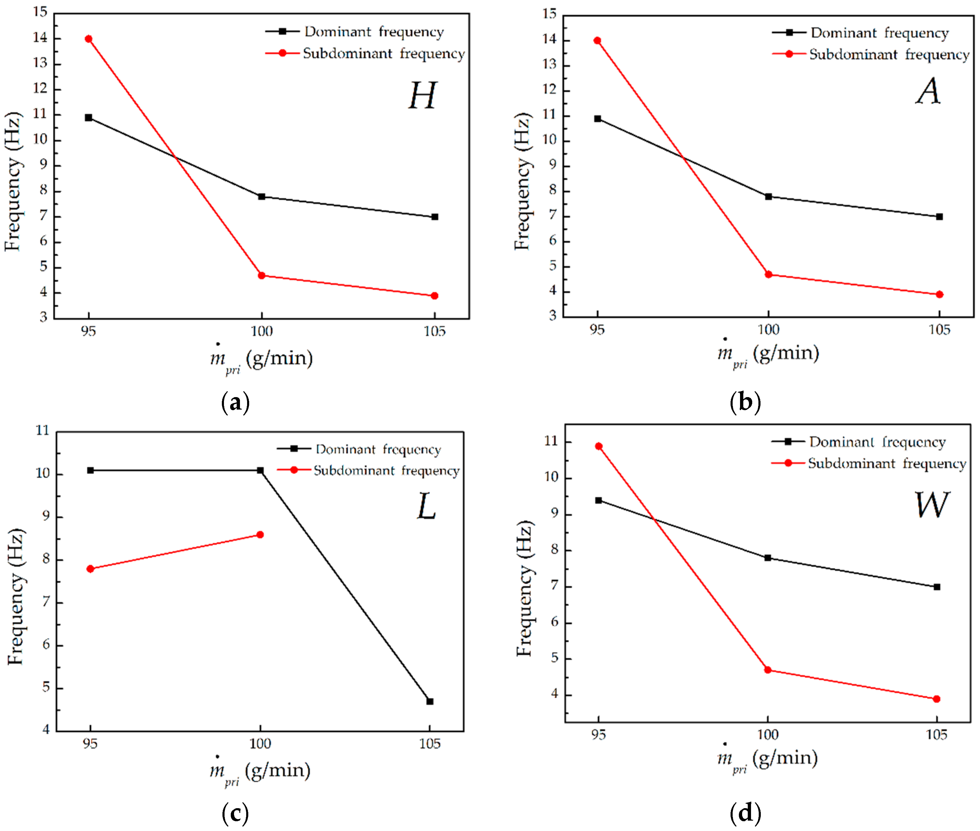
As illustrated in Figure 8, the flame heat-release rate (Figure 8a), flame area (Figure 8b), and flame equivalent width (Figure 8d) have identical dominant frequency and sub-dominant frequency, this is consistent with the observation in Figure 6 that they have similar time traces. The dominant frequency and sub-dominant frequency both decreased with the increasing of ṁpri. The enhanced mixing between primary air and fuel probably is the cause for this result. The probability for relatively distant fuel and primary air particles to mix with each other before burning increased when ṁpri increased, resulting in the broadened region of fuel-lean/rich mixture. Thus, burning initiated in the premixing state enhanced low-temperature regions of flame. Meanwhile, reducing the high-temperature regions produced by the pure diffusion combustion of entirely separated fuel and air [36]. Consequently, the overall flame temperature lowered, that caused weaker buoyancy, inducing low velocity vortex movement and thus triggered lowered frequency.
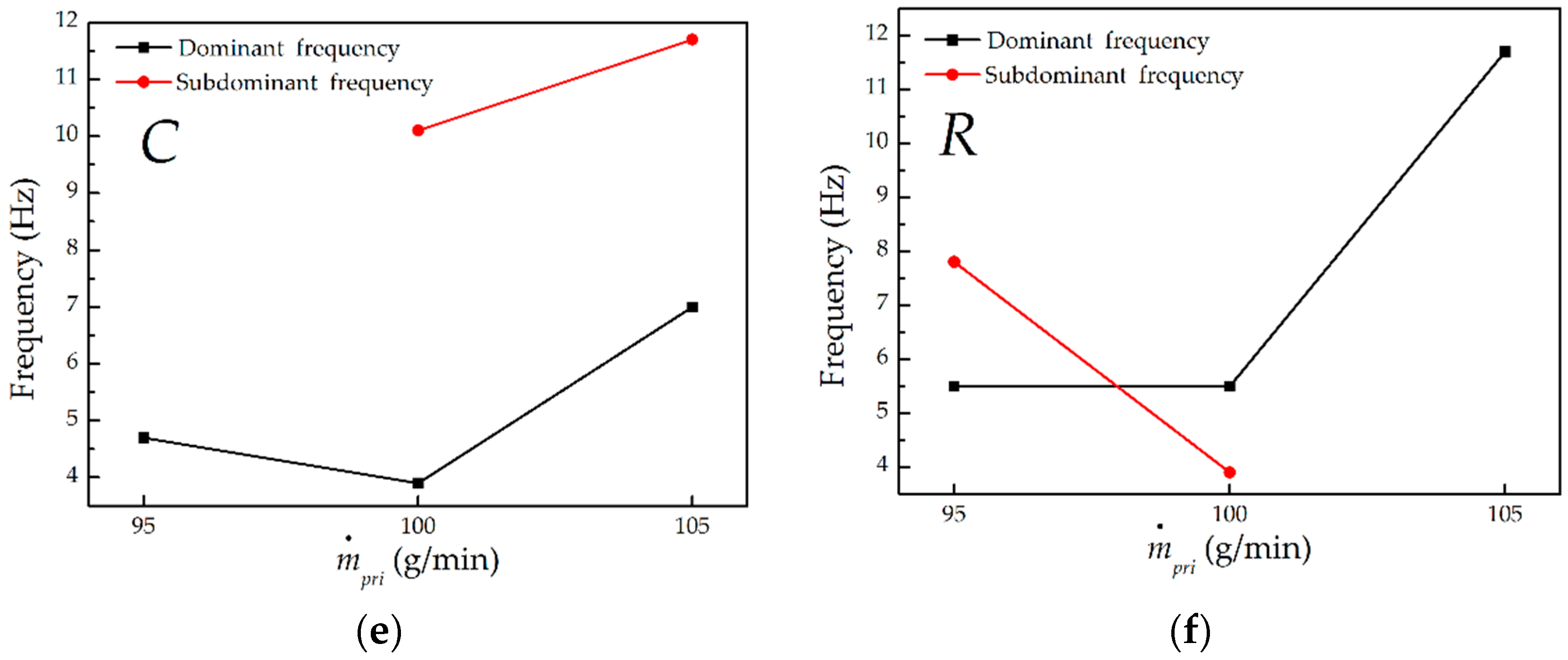
Different properties display different puffing behaviors. As for flame length in Figure 8c, its dominant frequency reduced but sub-dominant frequency increased with the increasing of ṁpri; but for flame center length in Figure 8e, both the dominant and sub-dominant frequency have an ascending trend as ṁpri increased; while for image correlation coefficient in Figure 8f, its dominant frequency increased but sub-dominant frequency declined at larger ṁpri. Although their frequencies and the varying trends of the frequency with ṁpri are diverse, yet all dominant and sub-dominant frequencies of flame properties are in the range of 3–14 Hz. These frequencies were compared with the frequencies predicted by some existing theoretical models based on non-swirl flames. The frequency f in these models merely relies on the injector diameter dj, as introduced before, f = Cdj−0.5, where C is a constant but varying in different models. The models and their predicted results are shown in Table 1, where dj is 0.01 m (the diameter of the nozzle throat which is considered as the exit of injector).
As displayed in Table 1, the calculated frequencies from the theoretical models are larger than the present measurement of swirl flame (3–14 Hz). This indicates that the puffing frequency of swirl flame does not only depend on the diameter of injector but also relies on the mass flow rate of primary air, that is to say, it was much more sensitive to the variation in ṁpri than the frequency of non-swirl flame. In addition, an accurate scaling of the puffing frequency with the mass flow rate of primary air may not be acquired at present as the current data is not much, while we will measure more experimental data to develop the scaling in the future.
3.4. Puffing Mean Value
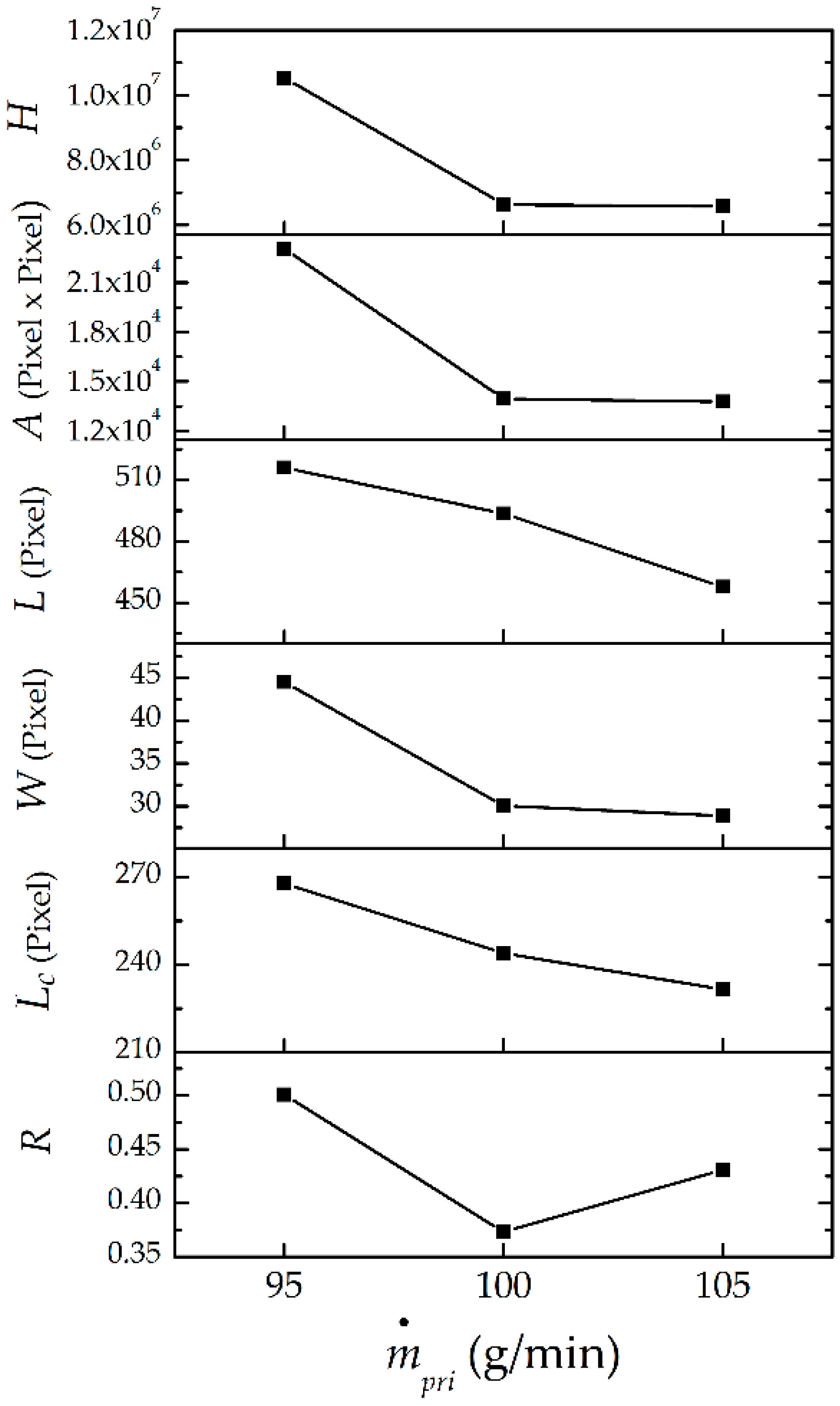
To calculate the normalized puffing amplitude in the next section, the time-mean value of flame properties was first determined. Each time-mean value can be obtained as the ratio between the integration of the corresponding property to time and the time length (1.28 s). The results are shown in Figure 9; one can see that all flame properties except the correlation coefficient have an overall decreasing trend with the increment of the mass flow rate of primary air. The decreasing flame area, flame length, and flame equivalent width are attributed to the declined air entrainment needed for dilution of the fuel to stoichiometric levels as ṁpri increased. Which resulted in the reduction of the heat-release rate because it is proportional to the flame area as stated before. Moreover, the decreased flame center length indicates that the flame moves upstream at higher ṁpri. The correlation coefficient exhibits unusual behavior, which firstly diminished and then increased when ṁpri increased. It can also be observed that the flame heat-release rate, flame area, and flame equivalent width almost have an identical variation trend, i.e., as ṁpri increased, they initially dropped and then remained nearly unchanged. The flame length and flame center length have a similar variation trend, i.e., they approximately uniformly descended with the increase in ṁpri. These time-averaged values were used to obtain the normalized amplitude.
3.5. Puffing Amplitude
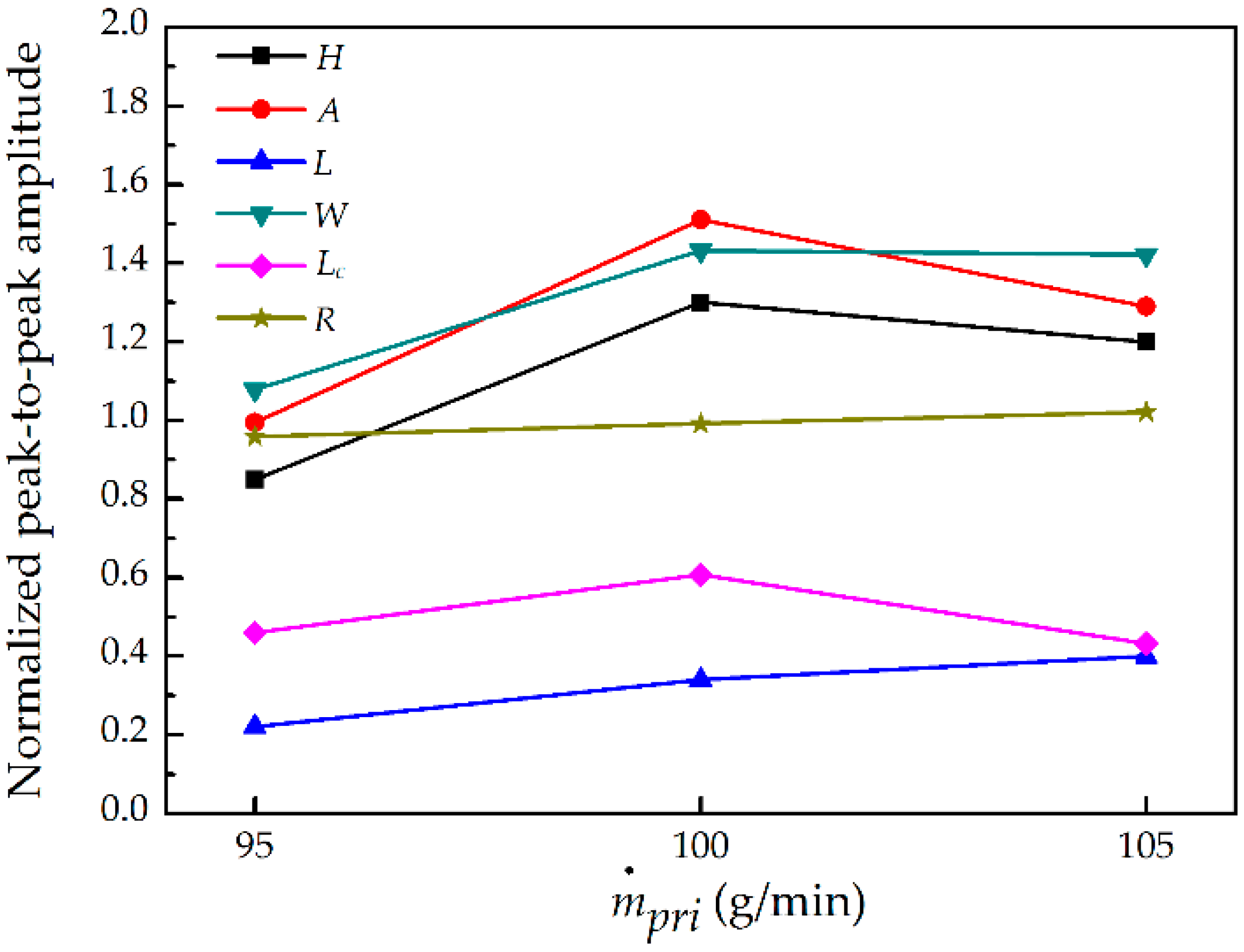
The peak-to-peak amplitude of flame puffing was normalized by the time-mean value obtained in Section 3.4; the results are presented in Figure 10. It can be found that the amplitude behaviors of flame properties are diverse, which can be summarized as the following. The normalized amplitude of flame heat-release rate, flame area, and flame center length have similar behavior, i.e., as ṁpri increased, the amplitude initially enlarged and then slightly decreased. While the amplitude of flame equivalent width increased with the increment of ṁpri (sharply at the beginning and mildly at the end). However, under increasing ṁpri, the amplitude of flame length evenly expanded but the amplitude of correction coefficient remained unchanged. One can also observe that the amplitude of flame length is the smallest in all properties, this indicates that the oscillating intensity of flame length is the most weakened. While the amplitude of the flame area and flame equivalent width are the largest, this implies both properties have the strongest oscillating level. Consequently, it can be inferred that the flame oscillation in width direction is much more intense than the oscillation in length direction; the flame puffing is mainly attributed to the oscillation in width direction.
4. Conclusions
The puffing behavior of a swirl partially premixed flame under varying mass flow rate of primary air ṁpri was explored by performing an experiment. The puffing dynamics were analyzed, and the puffing frequency and amplitude were obtained. The main findings of this study are listed as follows:
- (1)
- Flame puffing was caused by the movements of large vortices around the flame surface due to the buoyancy. During the puffing process, some instability phenomena were also observed which gave a deeper insight into the understanding about the puffing. The observed phenomena include the local auto-ignition around the flame base, the variation in the height of flame liftoff, local extinction around the flame tip, and the production of isolated small flame regions.
- (2)
- Almost each spectrum had two fundamental frequencies: dominant frequency and sub-dominant frequency, other frequencies in the same spectrum are found to be their harmonic frequencies. This is different with the amplitude-frequency characteristic of non-swirl flame, which always has a single-peak spectrum. The appearance of multiple frequencies may be due to the occurrence of the spiral flow field in swirl flame, which leads to the complex flame oscillation behavior.
- (3)
- The flame heat-release rate, flame area, and flame equivalent width had identical dominant frequency and sub-dominant frequency, both of which decreased with the increase in ṁpri. This was attributed to the decreased overall flame temperature caused by the improved mixing of fuel and primary air. Although other properties exhibit different frequency behaviors, all frequencies are in the range of 3–14 Hz.
- (4)
- The predicted frequencies from the theoretical models based on non-swirl flame are larger than the present measurement of swirl flame. Which indicates that the puffing frequency of swirl flame not only depends on the diameter of injector but also relies on the mass flow rate of primary air. Alternatively, it was much more sensitive to the variation in ṁpri than the frequency of non-swirl flame.
- (5)
- The time-mean values of all flame properties, except the correlation coefficient, have an overall decreasing trend with the increment of ṁpri. The decreasing flame area, flame length, and flame equivalent width were attributed to the declined air entrainment requirement for dilution of the fuel to the stoichiometric ratio as ṁpri increased. Which resulted in the reduction of the heat-release rate, since it is proportional to the flame area.
- (6)
- The normalized peak-to-peak amplitude behavior of flame properties is diverse. In all properties, the amplitude of flame length is the smallest with the most weakened oscillating intensity. While the amplitude of the flame area and flame equivalent width are the largest two, with the strongest oscillating level. Consequently, it can be inferred that the flame oscillation in width direction is more intensified than the oscillation in length direction, so the flame puffing is mainly attributed to the oscillation in width direction.
Author Contributions
Conceptualization, Z.X. and Z.F.; Methodology, Z.X.; Software, X.H.; Validation, Z.X., X.H., and Y.J.; Formal Analysis, Z.X.; Investigation, Z.X.; Resources, Z.X.; Data Curation, X.H.; Writing-Original Draft Preparation, Z.X.; Writing-Review & Editing, S.W.S.; Visualization, Y.J.; Supervision, Z.F.; Project Administration, Z.F.; Funding Acquisition, Z.F.
Funding
This research was funded by Beijing Natural Science Foundation (Grant No. 3162030) and the Fundamental Research Funds for the Central Universities (Grant No. 2017XS134).
Conflicts of Interest
The authors declare no conflicts of interest.
References
- Malalasekera, W.M.G.; Versteeg, H.K.; Gilchrist, K. A review of research and an experimental study on the pulsation of buoyant diffusion flames and pool fires. Fire Mater. 1996, 20, 261–271. [Google Scholar] [CrossRef]
- Pan, K.L.; Li, C.C.; Juan, W.C.; Yang, J.T. Low-frequency oscillation of a non-premixed flame on a bluff-body burner. Combust. Sci. Technol. 2009, 181, 1217–1230. [Google Scholar] [CrossRef]
- Sahu, K.B.; Kundu, A.; Ganguly, R.; Datta, A. Effects of fuel type and equivalence ratios on the flickering of triple flames. Combust. Flame 2009, 156, 484–493. [Google Scholar] [CrossRef]
- Bahadori, M.Y.; Zhou, L.; Stocker, D.P.; Hegde, U. Functional dependence of flame flicker on gravitational level. Aiaa J. 2001, 39, 1404–1406. [Google Scholar] [CrossRef]
- Durox, D.; Yuan, T.; Villermaux, E. The effect of buoyancy on flickering in diffusion flames. Combust. Sci. Technol. 1997, 124, 277–294. [Google Scholar] [CrossRef]
- Arai, M.; Sato, H.; Amagai, K. Gravity effects on stability and flickering motion of diffusion flames. Combust. Flame 1999, 118, 293–300. [Google Scholar] [CrossRef]
- Hamins, A.; Yang, J.C.; Kashiwagi, T. An experimental investigation of the pulsation frequency of flames. Symp. Combust. 1992, 24, 1695–1702. [Google Scholar] [CrossRef]
- Cetegen, B.M.; Kasper, K.D. Experiments on the oscillatory behavior of buoyant plumes of helium and helium-air mixtures. Phys. Fluids 1996, 8, 2974–2984. [Google Scholar] [CrossRef]
- Bejan, A. Predicting the pool fire vortex shedding frequency. J. Heat Transf. 1991, 113, 261. [Google Scholar] [CrossRef]
- Pagni, P.J. Pool vortex shedding frequencies. Appl. Mech. Rev. 1990, 43, 160. [Google Scholar]
- Yilmaz, N.; Lucero, R.E.; Donaldson, A.B.; Gill, W. Flow characterization of diffusion flame oscillations using particle image velocimetry. Exp. Fluids 2009, 46, 737–746. [Google Scholar] [CrossRef]
- Li, M.; Tong, Y.; Klingmann, J.; Thern, M. Impact of vitiation on a swirl-stabilized and premixed methane flame. Energies 2017, 10. [Google Scholar] [CrossRef]
- Fang, J.; Tu, R.; Guan, J.F.; Wang, J.J.; Zhang, Y.M. Influence of low air pressure on combustion characteristics and flame pulsation frequency of pool fires. Fuel 2011, 90, 2760–2766. [Google Scholar] [CrossRef]
- Yilmaz, N.; Burl Donaldson, A.; Edward Lucero, R. Experimental study of diffusion flame oscillations and empirical correlations. Energy Convers. Manag. 2008, 49, 3287–3291. [Google Scholar] [CrossRef]
- Pretrel, H.; Audouin, L. Periodic puffing instabilities of buoyant large-scale pool fires in a confined compartment. J. Fire Sci. 2013, 31, 197–210. [Google Scholar] [CrossRef]
- Cetegen, B.M.; Dong, Y. Experiments on the instability modes of buoyant diffusion flames and effects of ambient atmosphere on the instabilities. Exp. Fluids 2000, 28, 546–558. [Google Scholar] [CrossRef]
- Chen, Z.; Hu, L.; Huo, R.; Zhu, S. Flame oscillation frequency based on image correlation. J. Combust. Sci. Technol. 2008, 14, 367–371. [Google Scholar]
- Tang, F.; Hu, L.; Wang, Q.; Ding, Z. Flame pulsation frequency of conduction-controlled rectangular hydrocarbon pool fires of different aspect ratios in a sub-atmospheric pressure. Int. J. Heat Mass Transf. 2014, 76, 447–451. [Google Scholar] [CrossRef]
- Bennett, B.A.V.; McEnally, C.S.; Pfefferle, L.D.; Smooke, M.D.; Colket, M.B. Computational and experimental study of axisymmetric coflow partially premixed ethylene/air flames. Combust. Flame 2001, 127, 2004–2022. [Google Scholar] [CrossRef]
- Gore, J.P.; Zhan, N.J. NOx emission and major species concentrations in partially premixed laminar methane/air co-flow jet flames. Combust. Flame 1996, 105, 414–427. [Google Scholar] [CrossRef]
- Nguyen, Q.V.; Dibble, R.W.; Carter, C.D.; Fiechtner, G.J.; Barlow, R.S. Raman-LIF measurements of temperature, major species, OH, and NO in a methane-air Bunsen flame. Combust. Flame 1996, 105, 499–510. [Google Scholar] [CrossRef]
- Shu, Z.; Choi, C.W.; Aggakwal, S.K.; Katta, V.R.; Puri, I.K. Gravity effects on steady two-dimensional partially premixed methane- air flames. Combust. Flame 1999, 118, 91–107. [Google Scholar] [CrossRef]
- Cao, S.; Ma, B.; Bennett, B.A.V.; Giassi, D.; Stocker, D.P.; Takahashi, F.; Long, M.B.; Smooke, M.D. A computational and experimental study of coflow laminar methane/air diffusion flames: Effects of fuel dilution, inlet velocity, and gravity. Proc. Combust. Inst. 2015, 35, 897–903. [Google Scholar] [CrossRef] [Green Version]
- Liu, F.; Smallwood, G.J. Control of the structure and sooting characteristics of a coflow laminar methane/air diffusion flame using a central air jet: An experimental and numerical study. Proc. Combust. Inst. 2011, 33, 1063–1070. [Google Scholar] [CrossRef] [Green Version]
- Elbaz, A.M.; Zayed, M.F.; Samy, M.; Roberts, W.L.; Mansour, M.S. The flow field structure of highly stabilized partially premixed flames in a concentric flow conical nozzle burner with coflow. Exp. Therm. Fluid Sci. 2016, 73, 2–9. [Google Scholar] [CrossRef] [Green Version]
- Cao, S.; Ma, B.; Giassi, D.; Bennett, B.A.V.; Long, M.B.; Smooke, M.D. Effects of pressure and fuel dilution on coflow laminar methane–air diffusion flames: A computational and experimental study. Combust. Theory Model. 2018, 22, 316–337. [Google Scholar] [CrossRef]
- De Falco, G.; Moggia, G.; Sirignano, M.; Commodo, M.; Minutolo, P.; D’Anna, A. Exploring soot particle concentration and emissivity by transient thermocouples measurements in laminar partially premixed coflow flames. Energies 2017, 10. [Google Scholar] [CrossRef]
- Xi, Z.; Fu, Z.; Hu, X.; Sabir, S.W.; Jiang, Y. An experimental investigation on flame pulsation for a swirl non-premixed combustion. Energies 2018, 11, 1757. [Google Scholar] [CrossRef]
- Samaniego, J.-M.; Egolfopoulos, F.N.; Bowman, C.T. CO2* chemiluminescence in premixed flames. Combust. Sci. Technol. 1995, 109, 183–203. [Google Scholar] [CrossRef]
- Tachibana, S.; Kanai, K.; Yoshida, S.; Suzuki, K.; Sato, T. Combined effect of spatial and temporal variations of equivalence ratio on combustion instability in a low-swirl combustor. Proc. Combust. Inst. 2015, 35, 3299–3308. [Google Scholar] [CrossRef]
- Yoon, J.; Kim, M.K.; Hwang, J.; Lee, J.; Yoon, Y. Effect of fuel-air mixture velocity on combustion instability of a model gas turbine combustor. Appl. Therm. Eng. 2013, 54, 92–101. [Google Scholar] [CrossRef]
- Meier, W.; Weigand, P.; Duan, X.R.; Giezendanner-Thoben, R. Detailed characterization of the dynamics of thermoacoustic pulsations in a lean premixed swirl flame. Combust. Flame 2007, 150, 2–26. [Google Scholar] [CrossRef]
- Palacios, A.; Casal, J. Assessment of the shape of vertical jet fires. Fuel 2011, 90, 824–833. [Google Scholar] [CrossRef]
- Joo, S.; Yoon, J.; Kim, J.; Lee, M.; Yoon, Y. NOx emissions characteristics of the partially premixed combustion of H2/CO/CH4 syngas using artificial neural networks. Appl. Therm. Eng. 2015, 80, 436–444. [Google Scholar] [CrossRef]
- Figura, L.; Lee, J.G.; Quay, B.D.; Santavicca, D.A. The effects of fuel composition on flame structure and combustion dynamics in a lean premixed combustor. Turbo Expo 2007, 2, 181–187. [Google Scholar]
- Law, C.K. Chemical thermodynamics. In Combustion Physics; Cambridge University Press: New York, NY, USA, 2006. [Google Scholar]
Figure 1.
High-pressure combustion test rig schematic diagram.

Figure 2.
The combustor.

Figure 3.
The swirl burner.

Figure 4.
The flame size and location.

Figure 5.
A sequence of continuous flame surface topography for a typical condition.

Figure 6.
The time variation in flame properties under varying mass flow rate of primary air.

Figure 7.
The amplitude-frequency curves of flame properties for the mass flow rate of primary air: (a) the spectrum of flame heat-release rate; (b) the spectrum of flame area; (c) the spectrum of flame length; (d) the spectrum of flame equivalent width; (e) the spectrum of flame center length; and (f) the spectrum of correlation coefficient.

Figure 8.
The puffing frequency of flame properties for the mass flow rate of primary air: (a) the frequency of flame heat-release rate; (b) the frequency of flame area; (c) the frequency of flame length; (d) the frequency of flame equivalent width; (e) the frequency of flame center length; and (f) the frequency of correlation coefficient.


Figure 9.
The mean values of flame properties.

Figure 10.
The normalized peak-to-peak amplitude of flame puffing.


© 2018 by the authors. Licensee MDPI, Basel, Switzerland. This article is an open access article distributed under the terms and conditions of the Creative Commons Attribution (CC BY) license (http://creativecommons.org/licenses/by/4.0/).
Share and Cite
MDPI and ACS Style
Xi, Z.; Fu, Z.; Sabir, S.W.; Hu, X.; Jiang, Y. An Experimental Study on Flame Puffing of a Swirl Partially Premixed Combustion under Varying Mass Flow Rate of Primary Air. Energies 2018, 11, 1916. https://doi.org/10.3390/en11071916
AMA Style
Xi Z, Fu Z, Sabir SW, Hu X, Jiang Y. An Experimental Study on Flame Puffing of a Swirl Partially Premixed Combustion under Varying Mass Flow Rate of Primary Air. Energies. 2018; 11(7):1916. https://doi.org/10.3390/en11071916
Chicago/Turabian StyleXi, Zhongya, Zhongguang Fu, Syed Waqas Sabir, Xiaotian Hu, and Yibo Jiang. 2018. "An Experimental Study on Flame Puffing of a Swirl Partially Premixed Combustion under Varying Mass Flow Rate of Primary Air" Energies 11, no. 7: 1916. https://doi.org/10.3390/en11071916
Note that from the first issue of 2016, this journal uses article numbers instead of page numbers. See further details here.