Temperature Estimation of Stator Winding in Permanent Magnet Synchronous Motors Using d-Axis Current Injection


1
Department of Electrical and Computer Engineering, Sungkyunkwan University, Suwon 16419, Korea
2
Intelligent Mechatronics Research Center, Korea Electronics Technology Institute (KETI), Bucheon 14502, Korea
*
Author to whom correspondence should be addressed.
Energies 2018, 11(8), 2033; https://doi.org/10.3390/en11082033
Submission received: 9 July 2018
/
Revised: 30 July 2018
/
Accepted: 30 July 2018
/
Published: 6 August 2018
(This article belongs to the Special Issue Power Electronics 2018)
Abstract
:This paper presents a stator winding temperature detection method for permanent magnet synchronous motors (PMSMs) using a motor parameter estimation method. PMSM performance is highly dependent on the motor parameters. However, the motor parameters vary with temperature. It is difficult to measure motor parameters using a voltage equation without additional sensors. Herein, a stator winding temperature estimation method based on a d-axis current injection method is proposed. The proposed estimation method can be used to obtain stator temperatures and to achieve reliable operation. The validity of the proposed method is verified through simulations and experimental results.
1. Introduction
Permanent magnet synchronous motors (PMSMs) are widely employed in industrial drives, electric vehicles, renewable energy systems, etc., owing to their high torque density, high power density, and high efficiency [1]. The motors, primarily applied in drones and fans, are of the outer rotor type, in which the rotor is located outside and the stator is located inside. These motor types are surface-mounted permanent magnet synchronous motors (SPMSMs) with the same d-axis inductance and q-axis inductance. The torque is generated only by the q-axis current. In outer-rotor-type motors, the stator is located inside and temperature rises may occur and, as such, turn faults may occur as well. The life of the motor can be reduced by approximately 50% for every 10 °C increase in the stator winding temperature design limit [2,3]. The motor parameters are dependent on current and temperature. Due to high temperatures, or high currents, turn faults [4,5,6] in the stator may occur. Current can be easily measured using the current sensors of the inverter. However, it is difficult to obtain the internal temperature of the motor, especially that of the stator winding.
Among all temperature monitoring methods, the most accurate is to insulate temperature sensors [3]. However, the insulation of the temperature sensor is not cost-effective and temperature sensor reliability problems may occur. Motor internal temperature estimation methods can be classified into thermal model methods [7,8,9,10], and motor parameter estimation methods [11,12,13,14,15]. The lumped-parameter thermal network [7] is the most well-known thermal model method. The thermal model system is an eighth-order dynamic model, with many thermal capacitances and resistances, either directly acquired from various experimental tests, or derived from the dimensions and material thermal properties of the motor. However, with some assumptions in place, a few simplified thermal models have been proposed [8,9,10]. The computations are less complicated, but the thermal models are still significant with many model parameters able to be identified from simulations and experimental tests. The thermal model is highly dependent on the cooling system and the geometry of the motor, and specific analysis for each motor design and application is required. These results lead to limited applications and require long development times. In the parameter estimation method, stator resistance is used as the indicator of the stator winding temperature. This approach has significant advantages over the thermal model method. The accuracy of the stator temperature estimation is not affected by the motor specifications, cooling method, or operating conditions [11,12], and the stator resistance can be estimated from the electrical equivalent model of the motor [13]. However, the stator resistance is significantly small and the performance of the temperature estimation is too sensitive to motor inductance variations [2]. To improve the accuracy of the stator resistance estimation, an inductance map and back electromotive force (BEMF) map are required. The inductance map and BEMF map are identified from the simulations and experimental results. These factors lead to long development times being required.
This paper presents a stator winding temperature estimation method for motor systems without additional temperature sensors. To obtain the stator winding temperature, the motor parameters are estimated. The estimated parameters enable the stator winding temperature to be obtained because the parameters vary with temperature. For the motor parameter estimation, the d-axis current injection method is proposed. This paper is organized as follows: the principles and analysis of the SPMSM operation are presented in Section 2; the proposed estimation method is analyzed in Section 3; simulation and experimental results are described in Section 4 and Section 5 to evaluate the performance of the temperature estimation; and finally, conclusions are presented in Section 6.
2. Operations of PMSMs
The fundamental model of PMSMs in the synchronous reference frame is given by [14,15,16]:
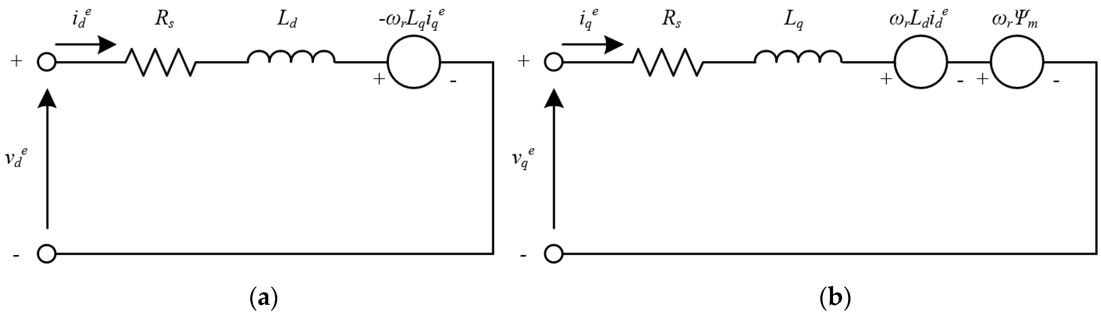
where ved,q and ied,q are the d-, q-axis stator voltage and current vectors in the synchronous reference frame, respectively. Rs and Ld,q are the stator resistance and d-, q-axis inductance. The equivalent circuit of PMSMs is shown in Figure 1. The motor speed and the rotor flux are denoted by ωr and ψm, respectively. p and P are the differential operator and the motor poles, respectively.
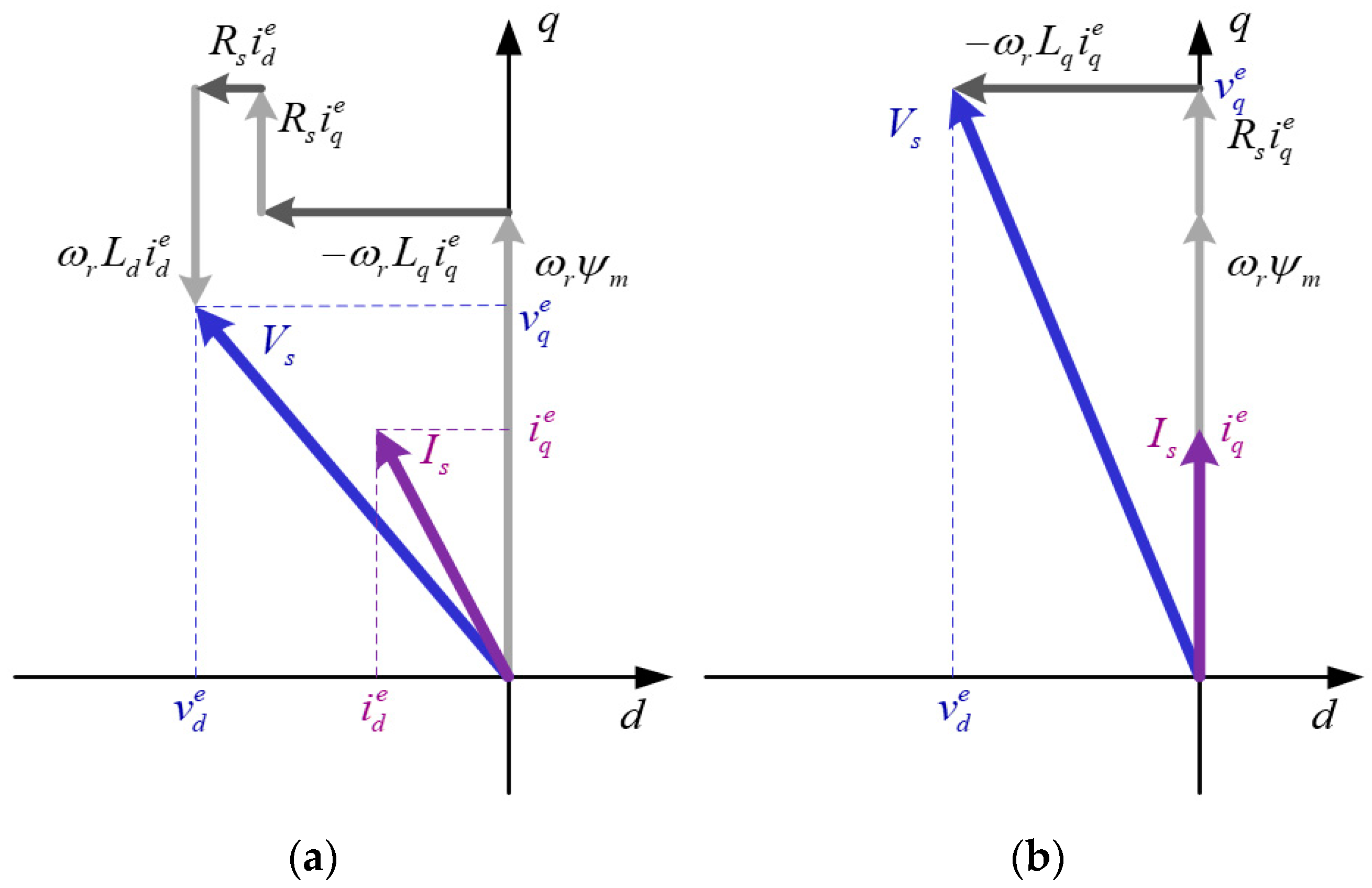
Assuming the steady-state condition, voltage Equation (1) can be approximated as Equation (2). It is noteworthy that ωrLd,qied,q are the coupling terms, and that ωrψm is the BEMF voltage. Based on Equation (2), the voltage and current vectors are described in Figure 2 [16].
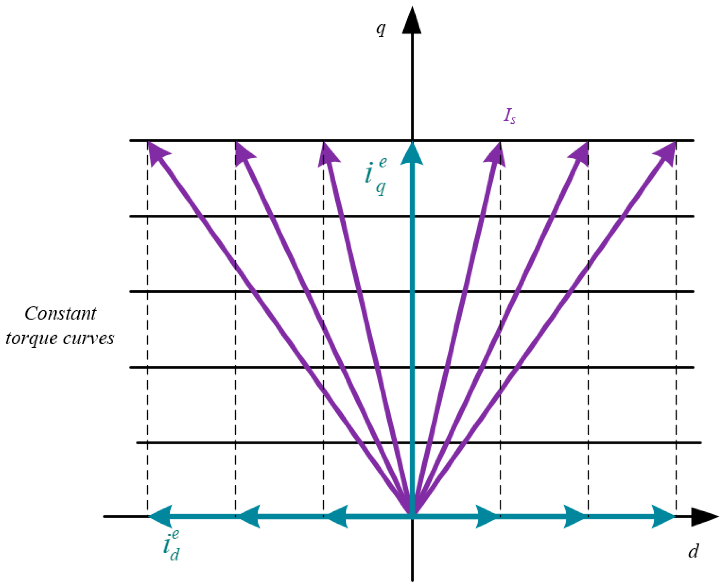
As shown in Equation (1), the electrical torque is composed of the magnetic torque and the reluctance torque. The magnetic torque is from the Lorentz force, and the reluctance torque is oriented from the Ld, Lq asymmetry [17,18]. Because the inductances Ld, Lq are equal for the SPMSMs, the reluctance torque becomes zero, and the torque equation can be rewritten as
The electrical torque for the SPMSMs can be controlled using the q-axis current. The constant torque curves of the SPMSMs are shown in Figure 3. The torque of the SPMSMs is generated by the q-axis current and the d-axis current does not contribute to torque generation.
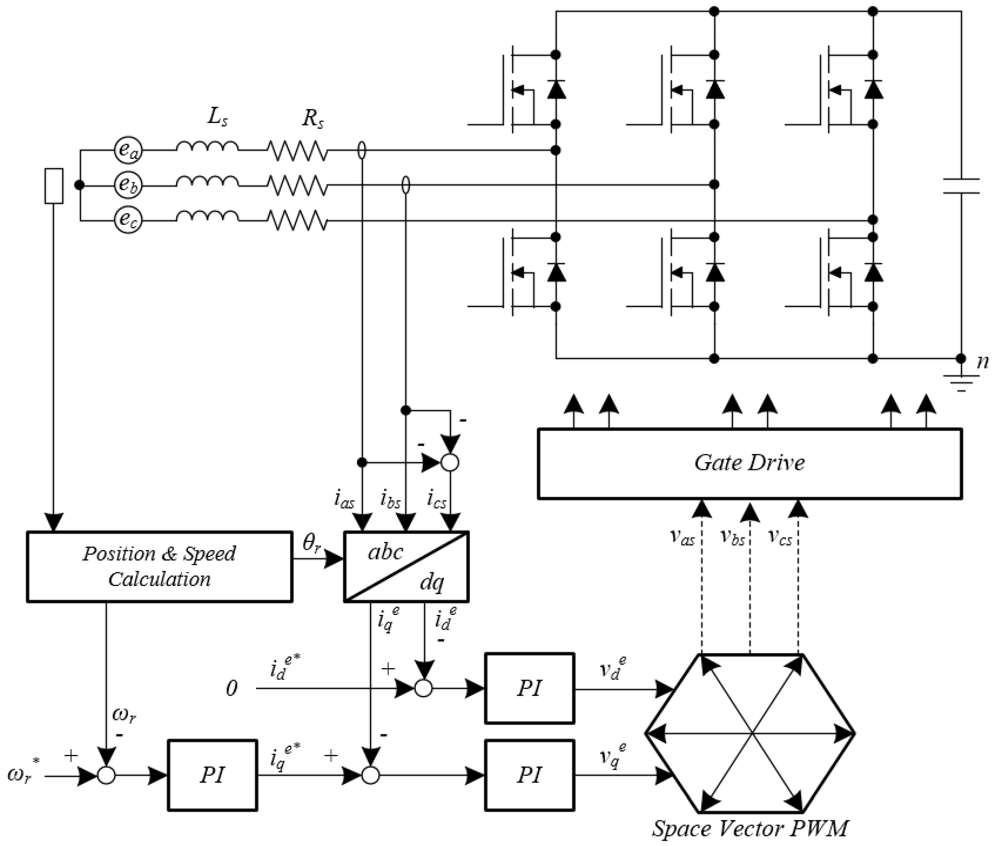
Figure 4 shows the conventional control configuration of SPMSMs for speed control. Because the torque of SPMSMs is generated by the q-axis current, the d-axis current command is set to zero, and the q-axis current is used to construct the speed controller. Information about position and speed is measured by the position sensor. The q-axis current command is determined by the speed controller, and the d-, q-axis current controllers generate the d-, q-axis voltage references. The pulse width modulation (PWM) duties are determined using the space vector PWM method, based on the voltage reference in the synchronous reference frame. Finally, PWM duties are applied to the power switch using the gate drive of the inverter.
3. Stator Winding Temperature Estimation Using d-Axis Current Injection
A temperature increase can cause several adverse effects [18,19]. For example, a temperature rise in the stator winding causes stator resistance variation and can degrade the stator winding insulation. The stator winding temperature can be detected through estimation of the stator resistance.
Under the steady-state condition, the voltage equation of PMSMs can be expressed as a variable depending on the temperature and current as
In Equation (4), Rs and ψm are functions of the stator and magnet temperatures, respectively. Ld,q are the functions of the magnet temperature and the stator current. Equation (4) can be rewritten as Equation (5), because the d-axis current becomes zero for the torque maximization of SPMSMs:
From Equation (5), the q-axis inductance can be expressed as Equation (6).
The stator temperature can be estimated through the calculation of the stator resistance, as in Equation (7). However, as the rotor flux can vary with the rotor temperature, the stator winding temperature estimation may exhibit low accuracy. This may cause a large error in the temperature estimation of the stator winding. Therefore, an additional equation is required to obtain the stator winding temperature.
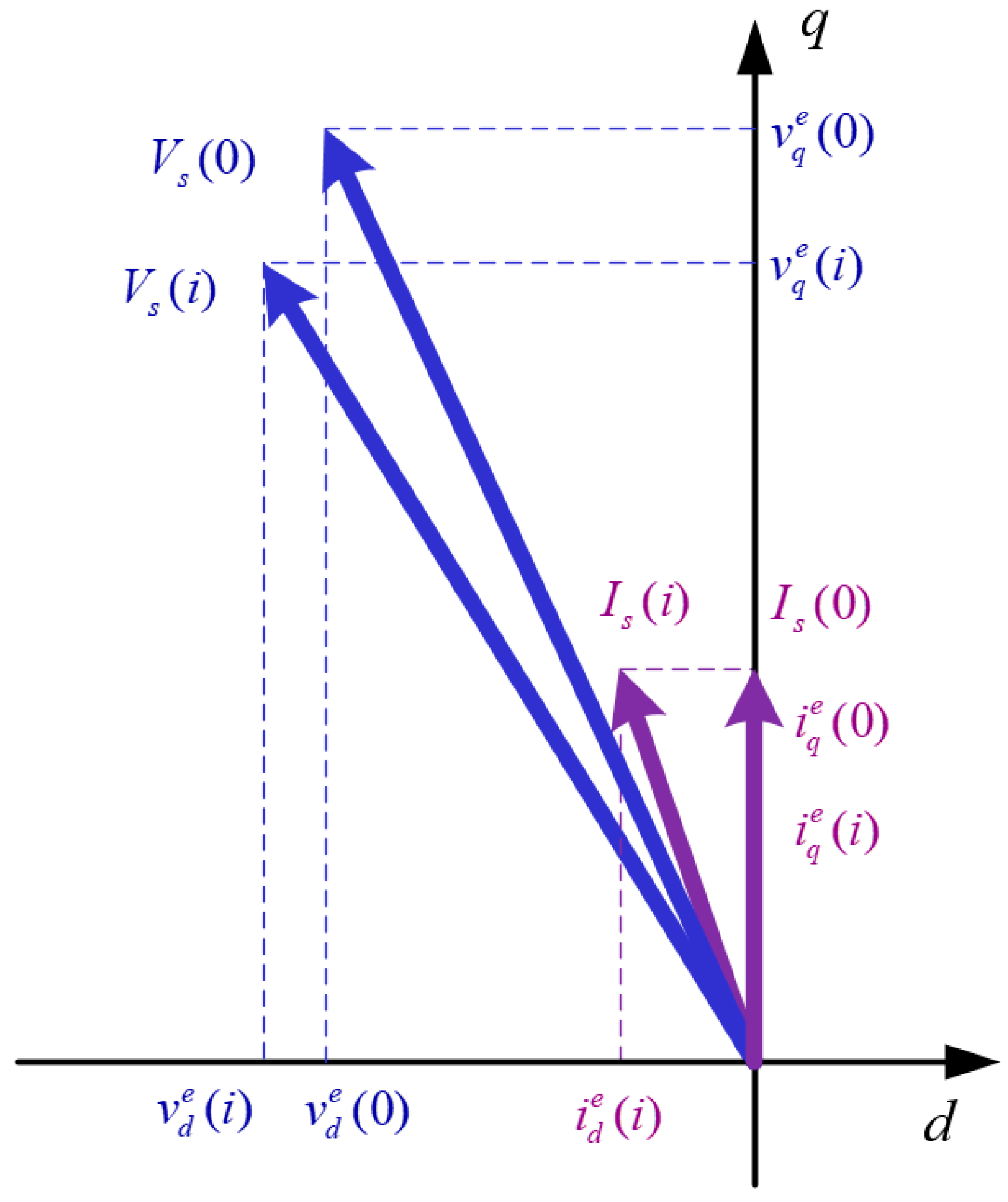
As mentioned in the previous section, the constant torque for the SPMSMs is maintained even if the d-axis current is applied while the constant q-axis current is generated. Under the constant torque operation, the motor speed is maintained, and Equation (4) can be expressed. Figure 5 shows voltage and current vectors for temperature estimation. The d-axis current injection can be performed while the q-axis current is constant. When the d-axis current i is injected, the voltages and currents can be expressed as ved(i), veq(i), and ied(i), ieq(i), respectively. When ied = 0, the voltage and the current can be expressed as ved(0), veq(0), and ied(0), ieq(0), respectively. The voltage equation for generating the same torque can be summarized as Equations (8) and (9).
Because the currents, motor speed, and voltage can be measured or calculated by the current sensor, position sensor, and current controller output, the q-axis inductance can be calculated as Equation (10) from Equation (9). We can assume Equation (10) because the difference between the d-axis inductance and the q-axis inductance is sufficiently small.
Equation (10) can be substituted into Equation (8) and arranged as Equation (11). The phase resistance Rs can be derived by using Equations (11) and (12).
Based on finite element analysis (FEA), the SPMSMs can be modeled and analyzed. The Rs map according to the stator winding temperature can be obtained from the FEA results. The stator winding temperature can be estimated by comparing the calculated Rs with the temperature map. Analysis is not required regarding the inductance and the rotor flux variation according to the current vectors and the magnet temperature using FEA, because the d-, q-axis inductances can be calculated as shown in Equation (10) and the rotor flux is not required to calculate the stator resistance.
Figure 6 shows the control block-diagram of the proposed stator winding temperature estimation method using the motor parameter estimation for the SPMSMs. As described above, two equations, depending on whether the d-axis current is injected or not, are required for estimating the stator temperature. To detect the stator temperature, the output d-, q-axis currents, the applied d-, q-axis voltages, and the motor speed are stored when ied = 0. Subsequently, the d-axis current is applied in the same q-axis current to measure the output d-, q-axis currents, the applied d-, q-axis voltages, and the motor speed. The d-axis current should be applied considering the current limit. After the detection of variables for the temperature estimation, the d-axis current is again applied at zero. The stator resistance is estimated using Equation (12). The stator winding temperature is estimated using the look-up table obtained from FEA. An averaging filter can be used in consideration of inverter noise during data acquisition. The estimation time is determined by the response performance of the current controller and filtering. The stator winding temperature estimation procedure does not need to be continuously operated, and the stator winding temperature can be estimated by applying the d-axis current only when the stator winding temperature is required. A rectangular d-axis current, can be used to estimate the stator winding temperature.
4. Simulation Results
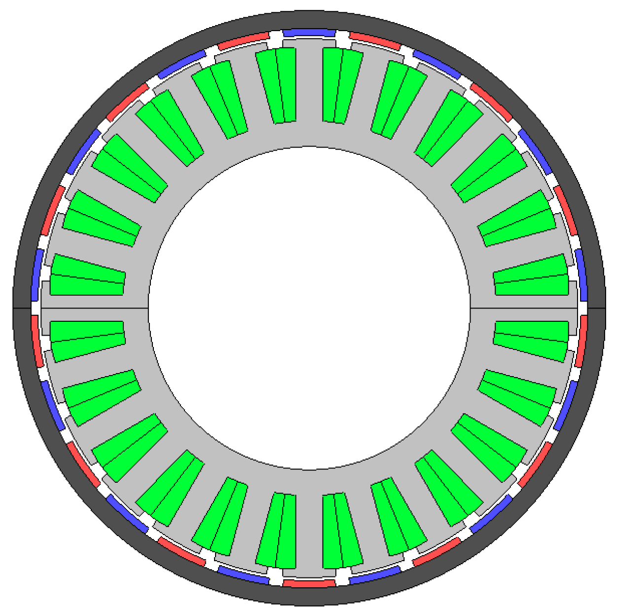
Finite element modeling (FEM) was used for the verification of motor parameter variation. The motor design used for the motor parameter variation simulation with temperature is shown in Figure 7, and the motor parameters at 20 °C are shown in Table 1.
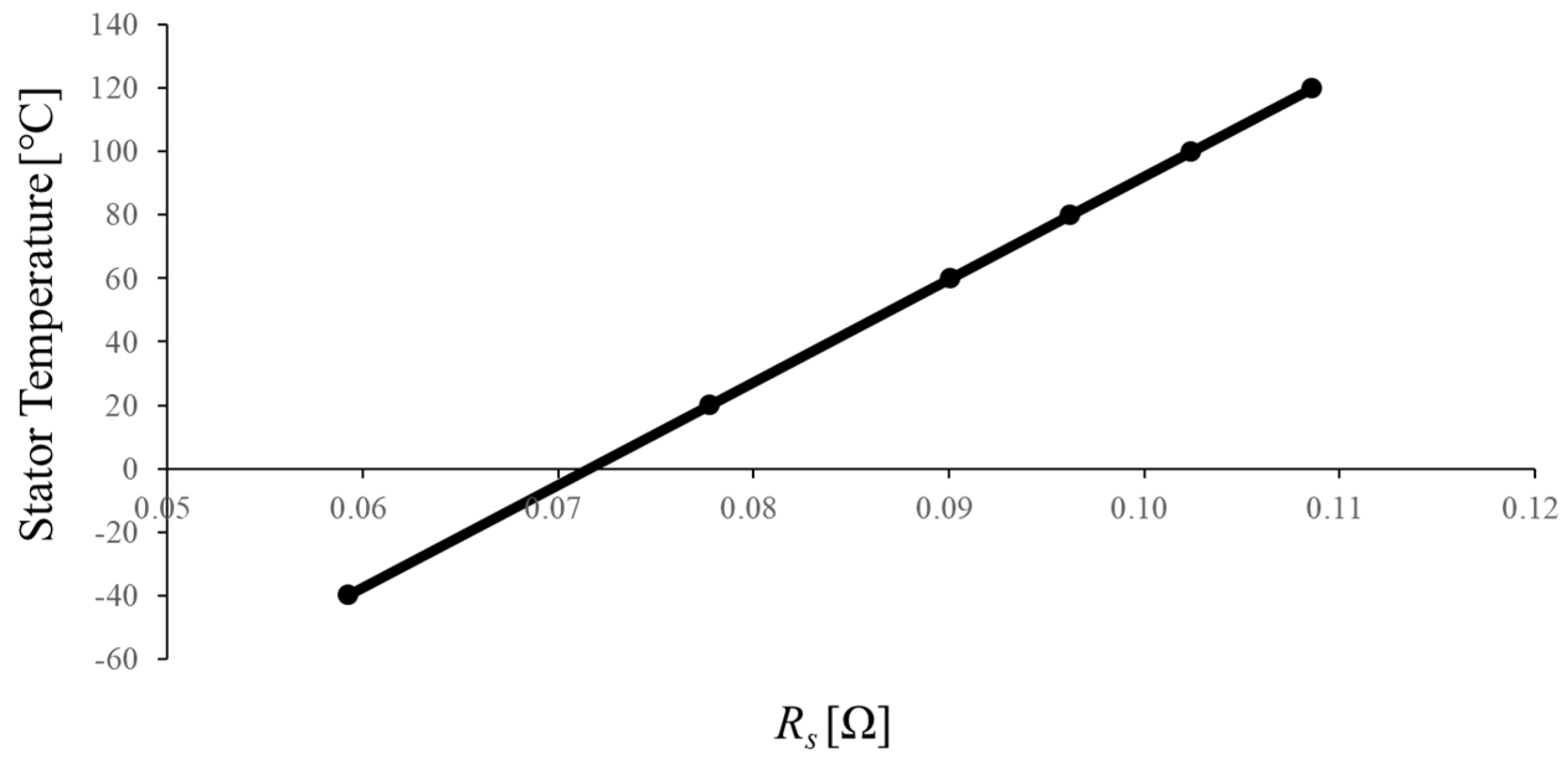
Figure 8 shows the stator resistance as a function of temperature. As the temperature increases, the stator resistance increases. The stator resistance can be calculated from Equation (12). The stator winding temperature can be estimated using the resistance table as shown in Figure 8.
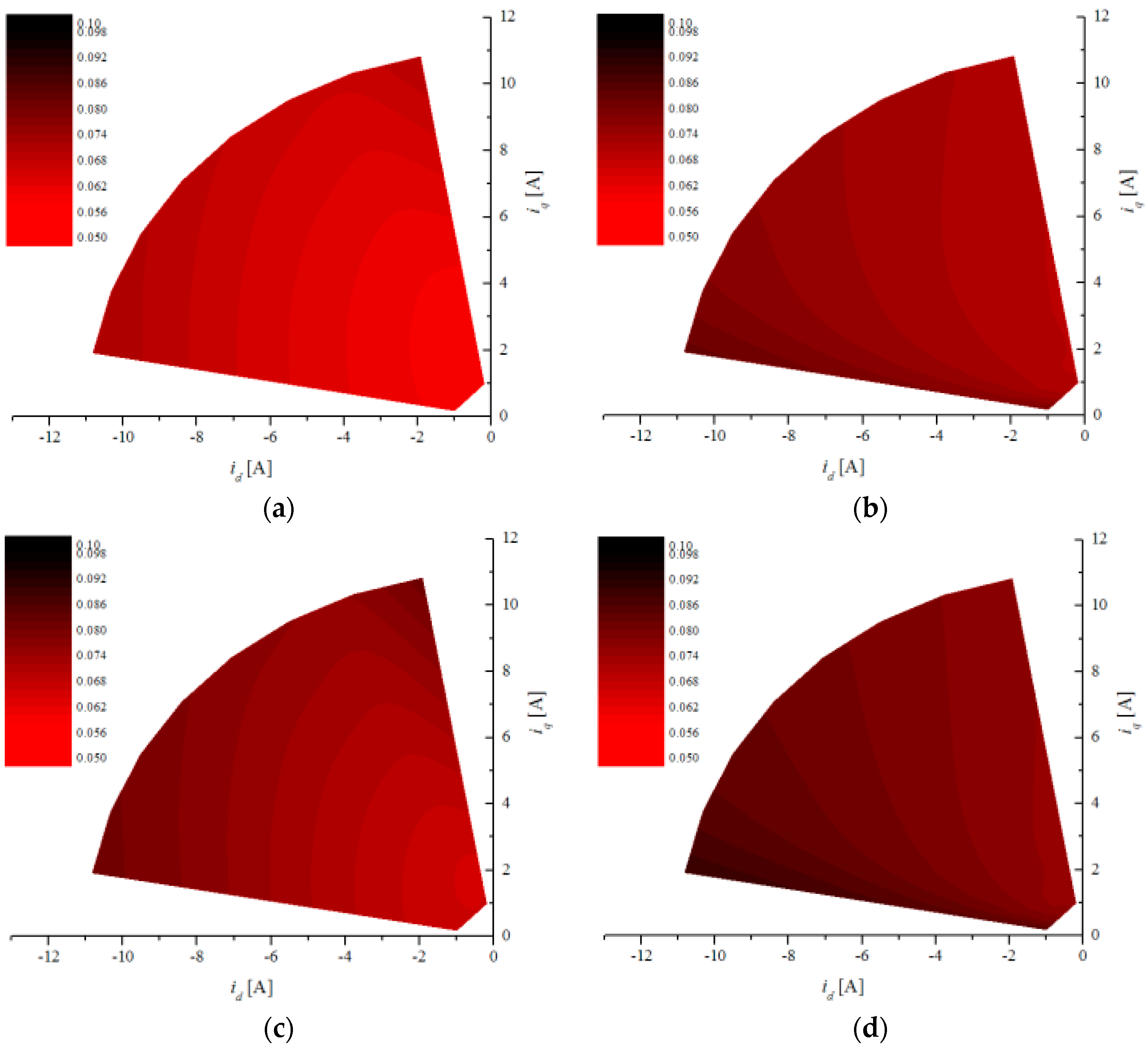
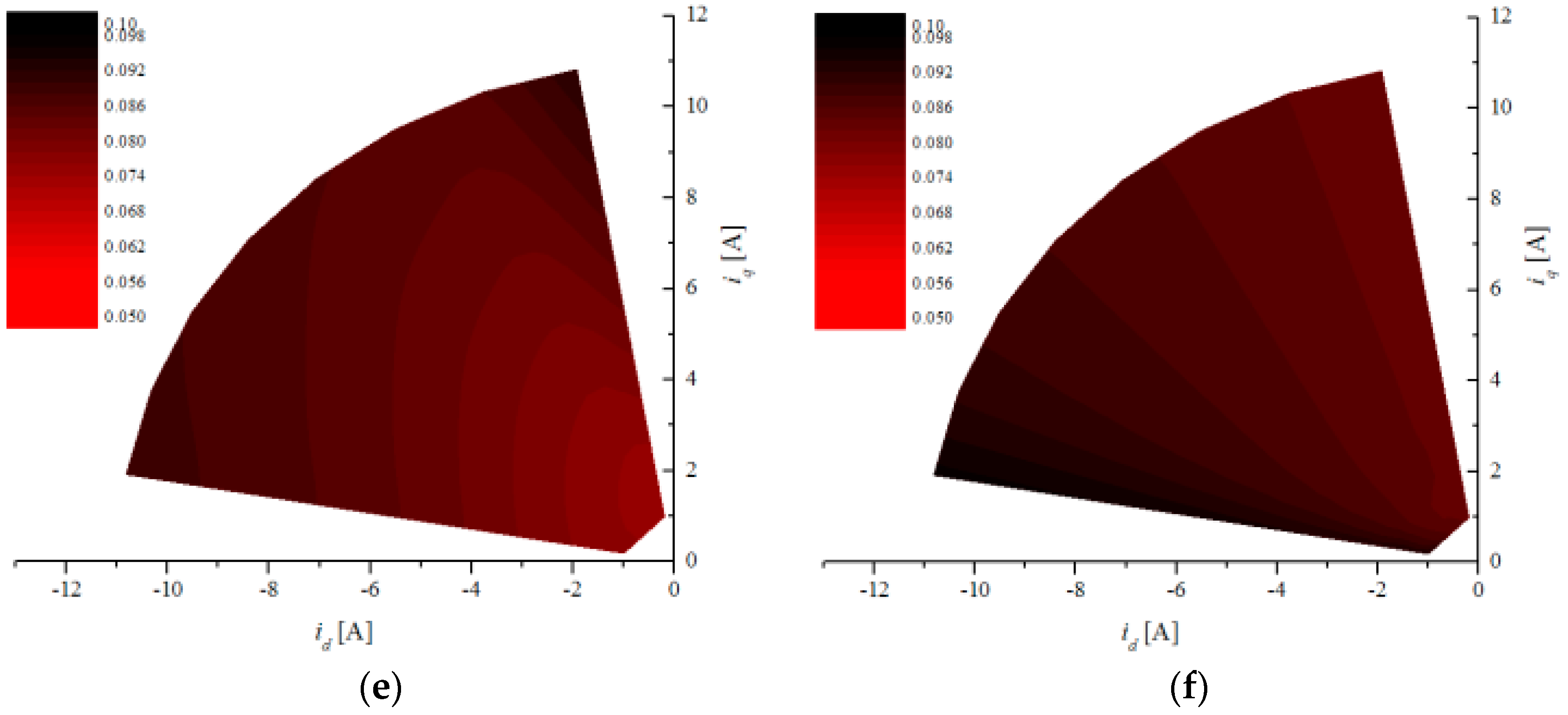
Figure 9 shows the d- and q-axis inductance maps according to id and iq at 20 °C. Unlike stator resistance, motor inductance varies with rotor temperature and current. Therefore, the inductance in the simulation should vary according to the temperature and the current. The inductance map was derived from the FEM analysis and applied to motor modeling.
The basic parameters of the SPMSM are listed in Table 1. The motor parameters with nonlinear characteristics, as shown in Figure 8 and Figure 9, were applied using a look-up table. The proposed estimation method of motor parameter Rs was modeled and simulated in MATLAB Simulink. The motor model for the simulation is shown in Figure 10. The stator resistance was determined by the stator resistance table according to the stator winding temperature. The inductances were determined by the inductance a three-dimensional table according to current and rotor temperature.
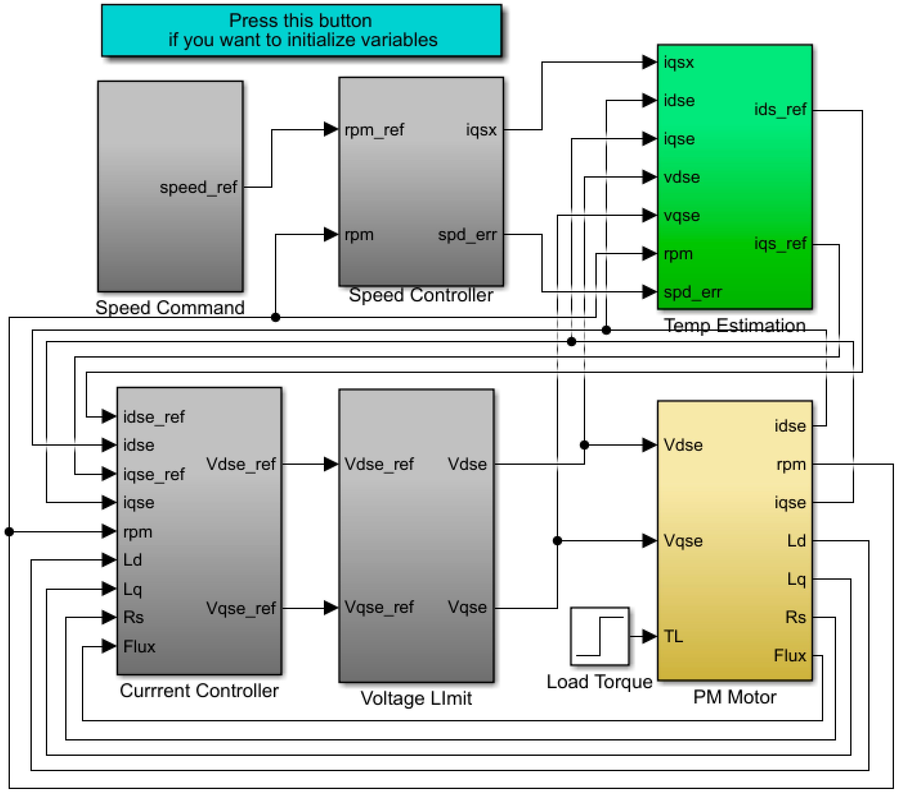
The SPMSM controller and the motor model were configured as shown in Figure 11, based on the speed controller. To verify the proposed method, the simulation for the temperature estimation method was performed at 1000 rpm and 0.2 Nm. The rotor and the stator temperatures were assumed to be 20 °C and 60 °C, respectively.
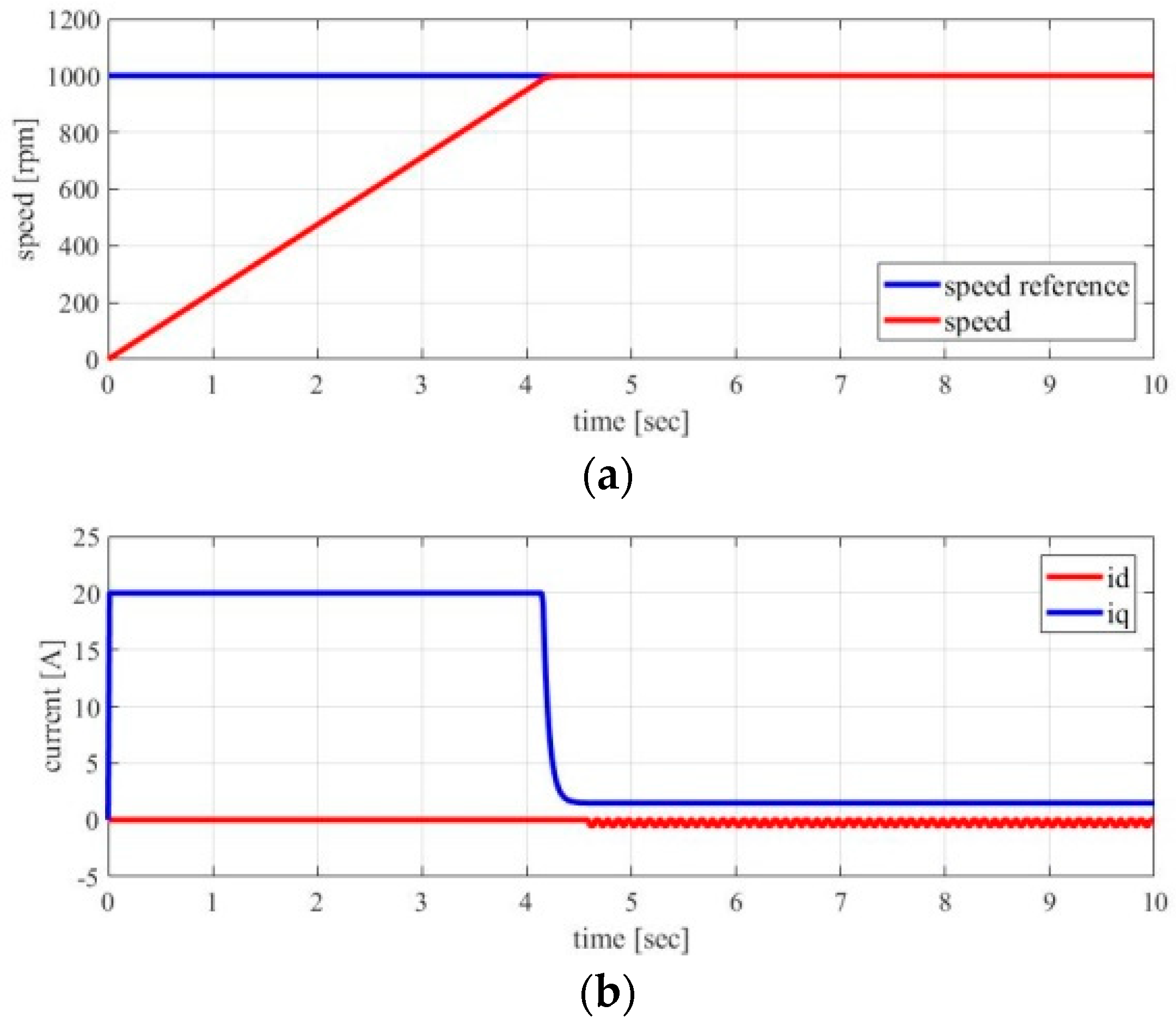
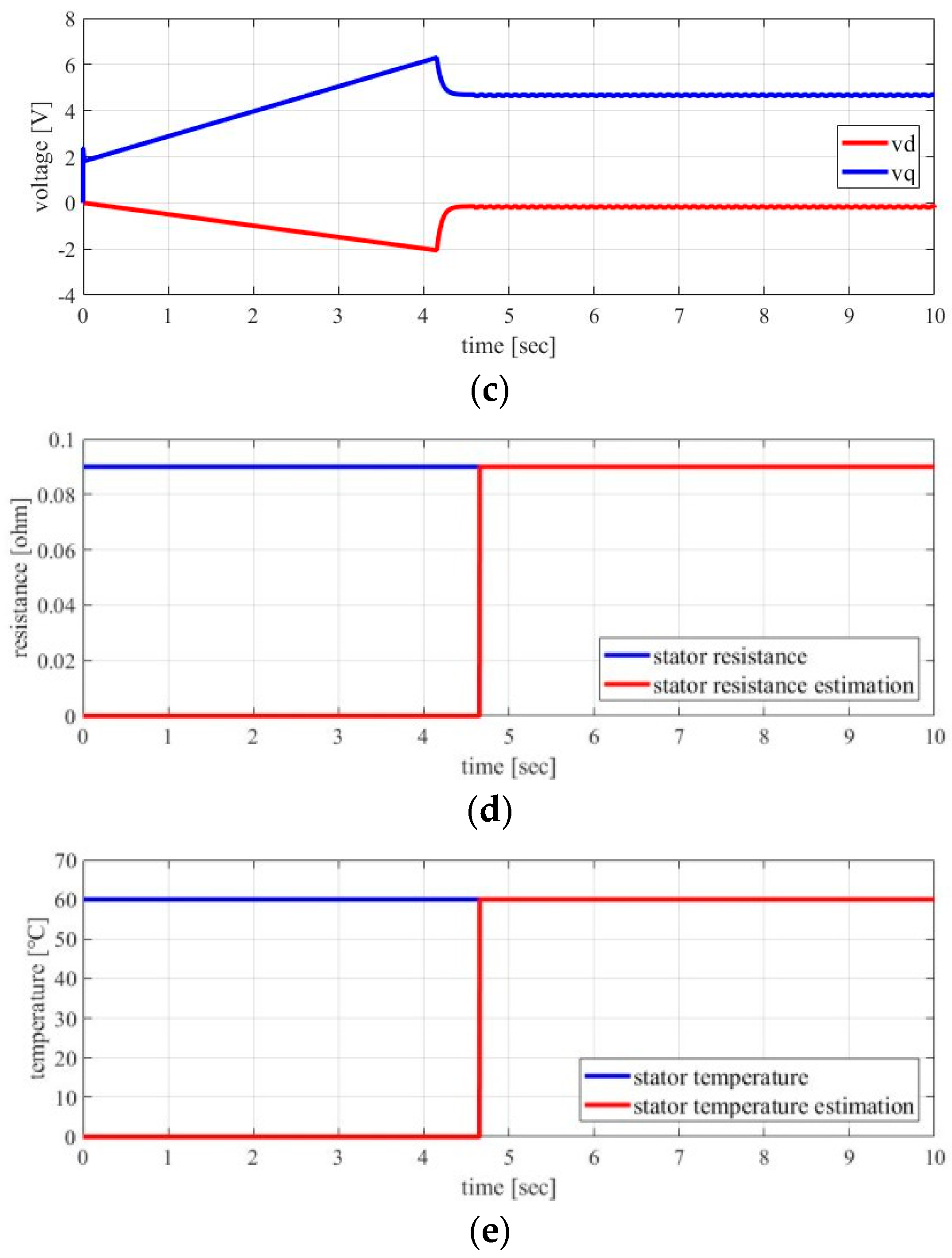
Figure 12 shows the simulation results for the stator winding temperature estimation. In the steady-state, where the target speed is reached, the motor parameter estimation method, through the d-axis current injection, is operating. The stator winding temperature was estimated through the motor parameter estimation. As shown in Figure 12, the stator winding temperature was estimated almost exactly.
5. Experimental Results
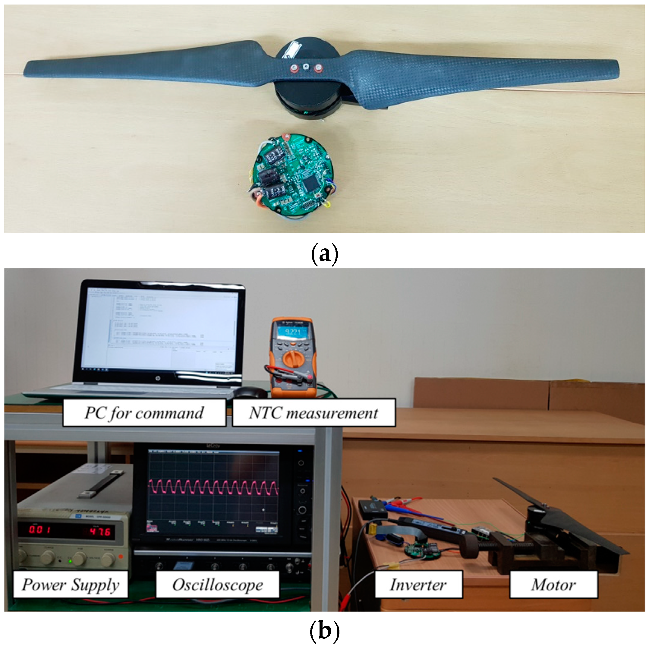
Figure 13 shows an experimental setup for validating the stator winding temperature estimation method, consisting of a prototype SPMSM and an inverter. The test motor is the outer-rotor-type for a drone, and the specifications are shown in Table 1. A 20 kHz PWM frequency was applied to the inverter, and the stator winding estimator was operated synchronously with the PWM frequency. For comparison with the estimation value, the negative temperature coefficient (NTC) thermistor 103NT-4-R025H34G temperature sensor was attached inside the stator winding. A characteristic of the NTC thermistor is that the resistance decreases when the temperature increases. The stator winding temperature was obtained from the NTC thermistor, and the accuracy of the estimated stator winding temperature was evaluated. For the competitive experiment, the test was carried out with the actual load fan. The stator winding temperature estimation was compared until temperature saturation at 1000 rpm, where the drone fan motor was mainly operated.
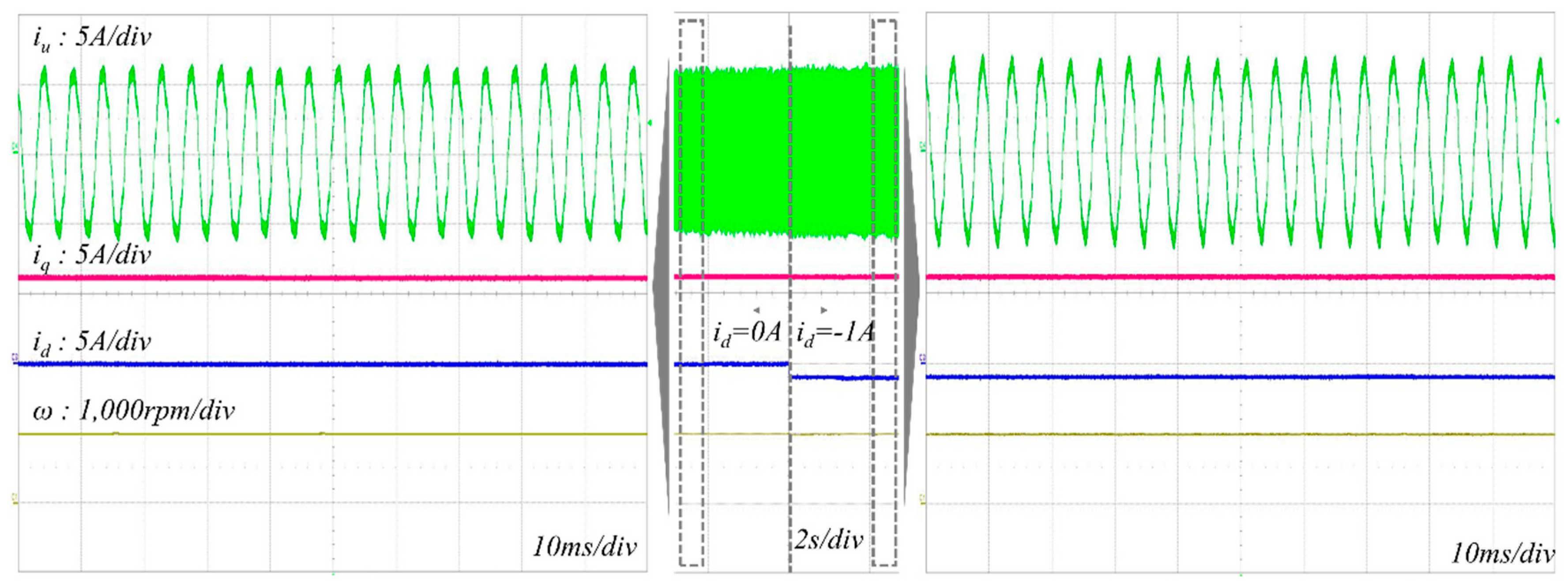
Figure 14 shows the phase current, q-axis current, and d-axis current waveforms for when the d-axis current was or was not injected at 1000 rpm. For estimating the stator winding temperature, a d-axis current of −1 A was injected. The magnitude of the phase current was slightly increased due to the d-axis current injection.
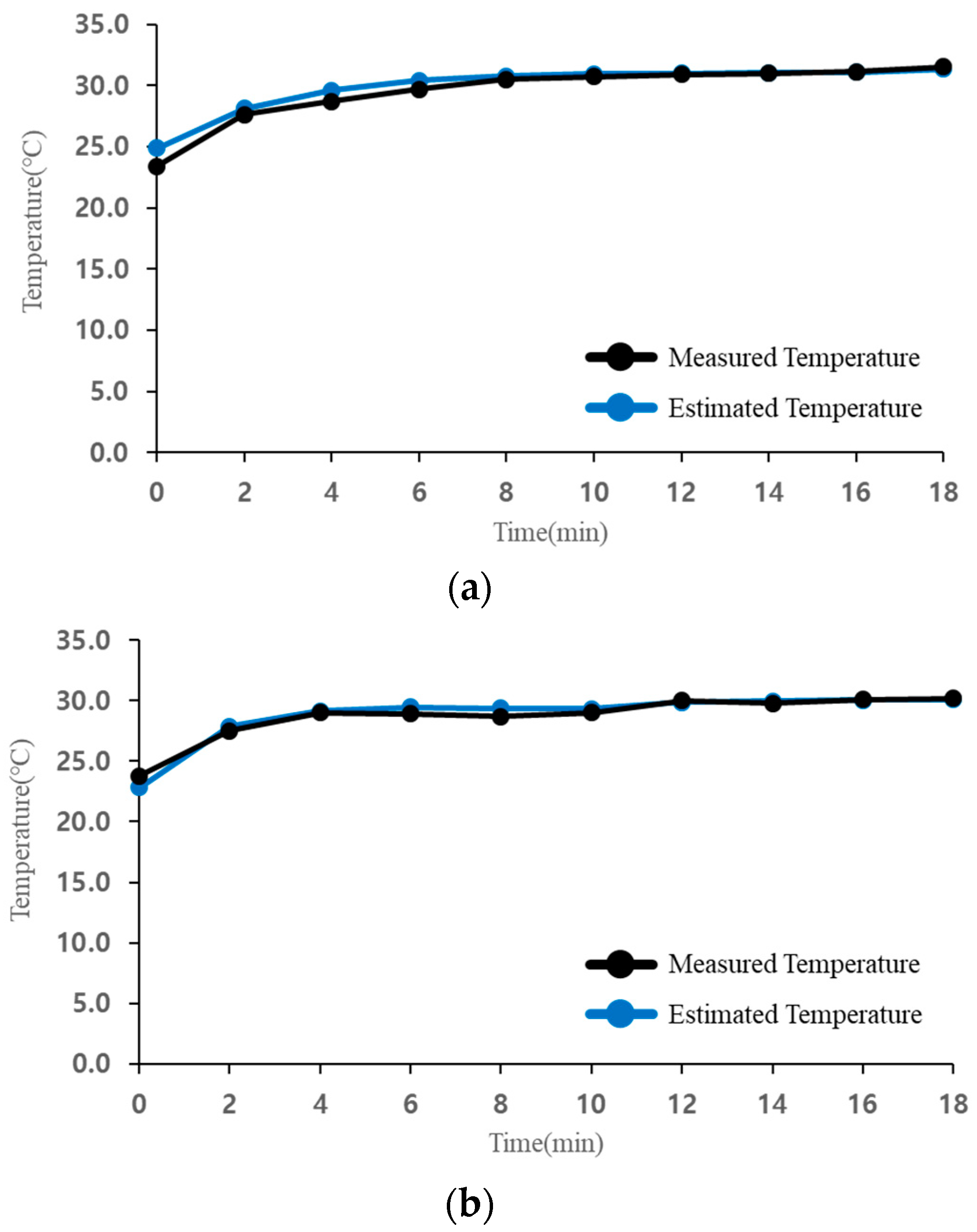
Figure 15 shows the stator winding temperature estimation results for no load and fluid load. At no load, stator temperature saturation occurred after approximately 8 min of motor operation, and the temperature increased to 32 °C. However, the stator temperature saturation occurred after approximately 2 min of motor operation at the fluid load, and the temperature increased to 30 °C. In the fluid load, the fan affects the temperature of the motor, and the stator temperature saturated at lower temperatures than at no load. The maximum error of temperature estimation was measured at approximately 2 °C. The stator winding temperature estimation was verified for both no load and fluid load.
6. Conclusions
We presented a stator winding temperature estimation method for SPMSMs without additional temperature sensors. To estimate the stator winding temperature, the stator resistance was estimated using the proposed d-axis current injection. To evaluate the possibilities for the proposed estimation method, simulations and experimental tests were performed. The test and simulation results showed similar trends. According to both the simulation and the test results, the proposed estimation method demonstrated potential for winding temperature estimation without additional temperature sensors. However, after estimating the stator winding temperature, a control strategy is needed to limit stator winding temperature in the SPMSM control system. Future work will focus on developing such a control strategy to limit stator winding temperature.
Author Contributions
B.-S.J. implemented mathematical modeling and performed the experimental test; J.S.P. designed and performed the control simulation; J.-H.C. analyzed the simulation and experimental results. K.-D.L. performed the simulation and analyzed the validated result data through FEM; C.-Y.W. guided and revised the manuscript. All authors discussed the results and contributed to writing the paper.
Funding
This research was funded by the Ministry of Trade, Industry & Energy (MOTIE, Korea) under Industrial Technology Innovation Program Grant 10063006, and by the Korea Institute of Energy Technology Evaluation and Planning (KETEP) and the the Ministry of Trade, Industry & Energy (MOTIE) of the Republic of Korea under Grant 20172010105270.
Conflicts of Interest
The authors declare no conflicts of interest.
References
- Reigosa, D.; Fernandez, D.; Tanimoto, T.; Kato, T. Comparative analysis of BEMF and pulsating high-frequency current injection methods for PM temperature estimation in PMSMs. IEEE Trans. Power Electron. 2017, 32, 3691–3699. [Google Scholar] [CrossRef]
- Zhang, P.; Lu, B.; Habetler, T.G. A remote and sensorless stator winding resistance estimation method for thermal protection of soft-starterconnected induction machines. IEEE Trans. Ind. Electron. 2008, 55, 3611–3618. [Google Scholar] [CrossRef]
- He, L.; Cheng, S.; Du, Y.; Harley, R.G.; Habetler, T.G. Stator temperature estimation of direct-torque-controlled induction machines via active flux or torque injection. IEEE Trans. Power Electron. 2015, 30, 888–899. [Google Scholar] [CrossRef]
- Choi, J.-H.; Gu, B.-G.; Won, C.-Y. Modeling and analysis of PMSMs under inter turn short faults. J. Electr. Eng. Technol. 2013, 8, 1243–1250. [Google Scholar] [CrossRef]
- Gu, B.-G. Study of IPMSM interturn faults part I: Development and analysis of models with series and parallel winding connections. IEEE Trans. Power Electron. 2016, 31, 5931–5943. [Google Scholar] [CrossRef]
- Gu, B.-G. Study of IPMSM interturn faults part II: Online fault parameter estimation. IEEE Trans. Power Electron. 2016, 31, 7214–7223. [Google Scholar] [CrossRef]
- Mellor, P.H.; Roberts, D.; Turner, D.R. Lumped parameter thermal model for electrical machines of TEFC design. IEE Proc. B Electr. Power Appl. 1991, 138, 205–218. [Google Scholar] [CrossRef]
- Bousbaine, A.; Mccormick, M.; Low, W.F. In-situ determination of thermal coefficients for electrical machines. IEEE Trans. Energy Convers. 1995, 10, 385–391. [Google Scholar] [CrossRef]
- Moreno, J.F.; Hidalgo, F.P.; Martinez, M.D. Realisation of tests to determine the parameters of the thermal model of an induction machine. IEE Proc. Electr. Power Appl. 2001, 148, 393–397. [Google Scholar] [CrossRef]
- Boglietti, A.; Cavagnino, A.; Lazzari, M.; Pastorelli, M. A simplified thermal model for variable speed self cooled industrial induction motor. IEEE Trans. Ind. Appl. 2003, 39, 945–952. [Google Scholar] [CrossRef]
- Cheng, S.; Du, Y.; Restrepo, J.A.; Zhang, P.; Habetler, T.G. A nonintrusive thermal monitoring method for closed-loop drive-fed induction machines. In Proceedings of the 2011 IEEE Energy Conversion Congress and Exposition, Phoenix, AZ, USA, 17–22 September 2011. [Google Scholar]
- Cheng, S.; Du, Y.; Restrepo, J.A.; Zhang, P.; Habetler, T.G. A nonintrusive thermal monitoring method for induction motors fed by closed-loop inverter drives. IEEE Trans. Power Electron. 2012, 27, 4122–4131. [Google Scholar] [CrossRef]
- Lee, S.B.; Habetler, T.G.; Harley, R.G.; Gritter, D.J. A stator and rotor resistance estimation technique for conductor temperature monitoring. In Proceedings of the Thirty-Fifth IAS Annual Meeting and World Conference on Industrial Applications of Electrical Energy, Italy, Rome, 8–12 October 2000. [Google Scholar]
- Uddin, M.N.; Radwan, T.S.; Rahman, M.A. Performance of interior permanent magnet motor drive over wide speed range. IEEE Trans. Energy Convers. 2002, 17, 79–84. [Google Scholar] [CrossRef]
- Nam, K. AC Motor Control and Electric Vehicle Applications; CRC Press: Boca Raton, FL, USA, 2010; ISBN 978-1-4398-1963-0. [Google Scholar]
- Park, J.S.; Nam, K. Dual inverter strategy for high speed operation of HEV permanent magnet synchronous motor. In Proceedings of the 2006 IEEE Industry Applications Conference Forty-First IAS Annual Meeting, Tampa, FL, USA, 8–12 October 2006. [Google Scholar]
- Sun, H.; Jing, K.; Dong, Y.; Zheng, Y. Current dynamically predicting control of PMSM targeting the current vectors. J. Electr. Eng. Technol. 2015, 10, 1058–1065. [Google Scholar] [CrossRef]
- Atallah, K.; Howe, D.; Stone, D. Rotor loss in permanent-magnet brushless AC machines. IEEE Trans. Ind. Appl. 2000, 36, 1612–1618. [Google Scholar] [CrossRef]
- Reigosa, D.D.; Briz, F.; Degner, M.W.; Garcia, P.; Guerrero, J.M. Magnet temperature estimation in surface PM machines during six-step operation. IEEE Trans. Ind. Appl. 2012, 48, 2353–2361. [Google Scholar] [CrossRef]
Figure 1.
Equivalent circuit of permanent magnet synchronous motors (PMSMs): (a) d-axis; (b) q-axis.
Figure 1.
Equivalent circuit of permanent magnet synchronous motors (PMSMs): (a) d-axis; (b) q-axis.

Figure 2.
Voltage and current vectors when: (a) ied < 0, ieq > 0; (b) ied = 0, ieq > 0.

Figure 3.
Constant torque curves for surface-mounted permanent magnet synchronous motors (SPMSMs).

Figure 4.
Conventional control configuration for SPMSMs.

Figure 5.
Voltage and current vectors for temperature estimation.

Figure 6.
Proposed control block-diagram for stator winding temperature estimation.

Figure 7.
SPMSM design.

Figure 8.
Motor parameter map according to stator winding temperature.

Figure 9.
d- and q-axis inductance maps: (a) Ld at −40 °C; (b) Lq at −40 °C; (c) Ld at 20 °C; (d) Lq at 20 °C; (e) Ld at 80 °C; (f) Lq at 80 °C.
Figure 9.
d- and q-axis inductance maps: (a) Ld at −40 °C; (b) Lq at −40 °C; (c) Ld at 20 °C; (d) Lq at 20 °C; (e) Ld at 80 °C; (f) Lq at 80 °C.


Figure 10.
Motor simulation model.

Figure 11.
Simulation model for stator winding estimation.

Figure 12.
Simulation results: (a) motor speed; (b) id and iq; (c) vd and vq; (d) stator resistance estimation; (e) stator winding temperature.
Figure 12.
Simulation results: (a) motor speed; (b) id and iq; (c) vd and vq; (d) stator resistance estimation; (e) stator winding temperature.


Figure 13.
(a) Test motor/inverter; (b) experimental setup.

Figure 14.
Phase current waveforms when d-axis current was injected at 1000 rpm.

Figure 15.
Stator winding temperature estimation results at (a) no load; (b) fluid load.


Table 1.
Motor parameters at 20 °C.
| Poles | Turns | Coil Diameter | Irated | Vdc | Slots | Connection | Rs | Ld/Lq | ψm |
|---|---|---|---|---|---|---|---|---|---|
| 26 | 19 | 0.6mm | 11 A | 52 V | 24 | Y | 0.0777 Ω | 0.08 mH | 0.00335 Wb |
© 2018 by the authors. Licensee MDPI, Basel, Switzerland. This article is an open access article distributed under the terms and conditions of the Creative Commons Attribution (CC BY) license (http://creativecommons.org/licenses/by/4.0/).
Share and Cite
MDPI and ACS Style
Jun, B.-S.; Park, J.S.; Choi, J.-H.; Lee, K.-D.; Won, C.-Y. Temperature Estimation of Stator Winding in Permanent Magnet Synchronous Motors Using d-Axis Current Injection. Energies 2018, 11, 2033. https://doi.org/10.3390/en11082033
AMA Style
Jun B-S, Park JS, Choi J-H, Lee K-D, Won C-Y. Temperature Estimation of Stator Winding in Permanent Magnet Synchronous Motors Using d-Axis Current Injection. Energies. 2018; 11(8):2033. https://doi.org/10.3390/en11082033
Chicago/Turabian StyleJun, Bum-Su, Joon Sung Park, Jun-Hyuk Choi, Ki-Doek Lee, and Chung-Yuen Won. 2018. "Temperature Estimation of Stator Winding in Permanent Magnet Synchronous Motors Using d-Axis Current Injection" Energies 11, no. 8: 2033. https://doi.org/10.3390/en11082033
Note that from the first issue of 2016, this journal uses article numbers instead of page numbers. See further details here.