Partial Redesign of an Accelerator Driven System Target for Optimizing the Heat Removal and Minimizing the Pressure Drops


1
GeNERG-DIME/TEC, University of Genova, via all’opera Pia 15/A, 16145 Genova, Italy
2
INFN, via Dodecaneso 33, 16146 Genova, Italy
*
Author to whom correspondence should be addressed.
†
Current address: F.I.P. S.p.A.-Loc., Pian di Parata, 16015 Casella (GE), Italy.
‡
Current address: Pompe Garbarino S.p.A.-via Marenco, 44-15011 Acqui Terme (AL), Italy.
Energies 2018, 11(8), 2090; https://doi.org/10.3390/en11082090
Submission received: 28 June 2018
/
Revised: 2 August 2018
/
Accepted: 6 August 2018
/
Published: 10 August 2018
(This article belongs to the Special Issue Nuclear Power, Including Fission and Fusion Technologies)
Abstract
:Accelerator Driven Systems (ADS) seem to be a good solution for safe nuclear waste transmutation. One of the most important challenges for this kind of machine is the target design, particularly for what concerning the target cooling system. In order to optimize this component a CFD-based approach has been chosen. After the definition of a reference design (Be target cooled by He), some parameters have been varied in order to optimize the thermal-fluid-dynamic features. The final optimized target design has an increased security margin for what regarding Be melting and reduces the maximum coolant velocity (and consequently even more the pressure drops).
1. Introduction
In the last years, different versions of Generation-IV and innovative nuclear systems have been studied and designed [1]. The most important effort has been probably applied to develop fast systems (both critical and sub-critical) and their key components and sub-systems (e.g., [2,3,4]). In the last category Accelerator Driven Systems (ADS) seem to be a good solution for a safe nuclear waste transmutation [5]. Around the world ADS machines have been built, for different purpose, both with thermal and fast neutron spectra, zero and low powers [6,7,8,9,10,11,12]. Some high power ADS have been designed and some others are under construction in order to build efficient nuclear waste burners. ADS, characterized by the presence of accelerated particles which colliding on a target, generate source neutrons via nuclear reactions (spallation and (p,n) for example) in order to drive the subcritical system. In such a kind of machine we can have different advantages: for example, operating with a subcritical fission assembly, it is possible to have the instantaneous reactor shutdown by switching off the beam, and the possibility to use different and new kind of fuels without problems related to the delayed neutron emissions [13].
One of the most important challenge is the thermal design, because a high power density is concentrated in a relatively small volume and both geometry and physical processes are quite far from standard systems design.
We produced a conceptual design of a low power machine [14,15] which can be considered as an intermediate step between the actual zero power and the future high power systems. This nuclear sub-critical fast system is driven by a 1-mA beam of 70-MeV protons impinging on a beryllium target via (p,n) reactions generating high energy neutrons. The initial target design was described in [16] and an experimental evaluation of neutron yield for a similar target was reported in [17].
As partially anticipated, a key issue is the design of the target cooling system, because the impinging proton beam deposits such 70 kW in this small volume. A helium cooling system was chosen in order to obtain the requested system characteristics [13,18]. In the following sections we will describe the main features of this helium cooling system for the target region.
2. Materials and Methods
2.1. Design of the Cooling System and Preliminary Theoretical Calculations
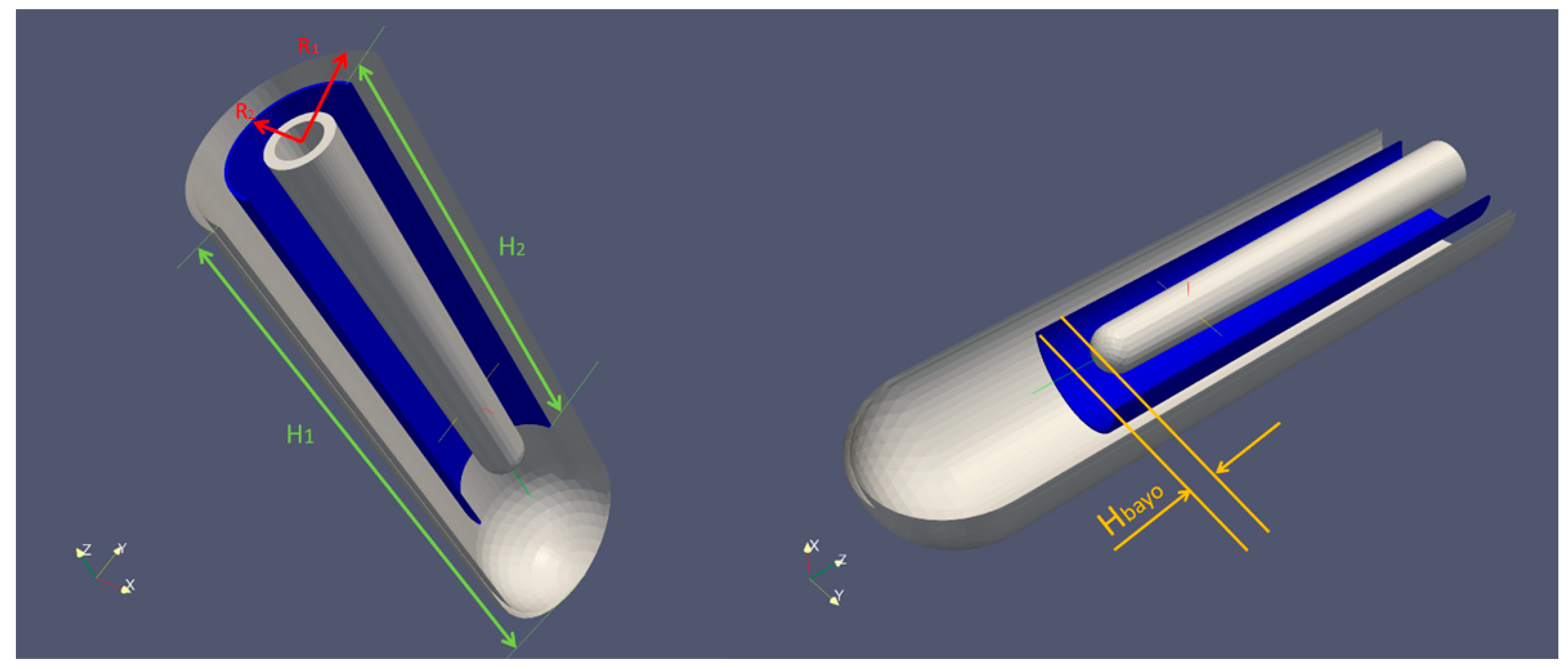
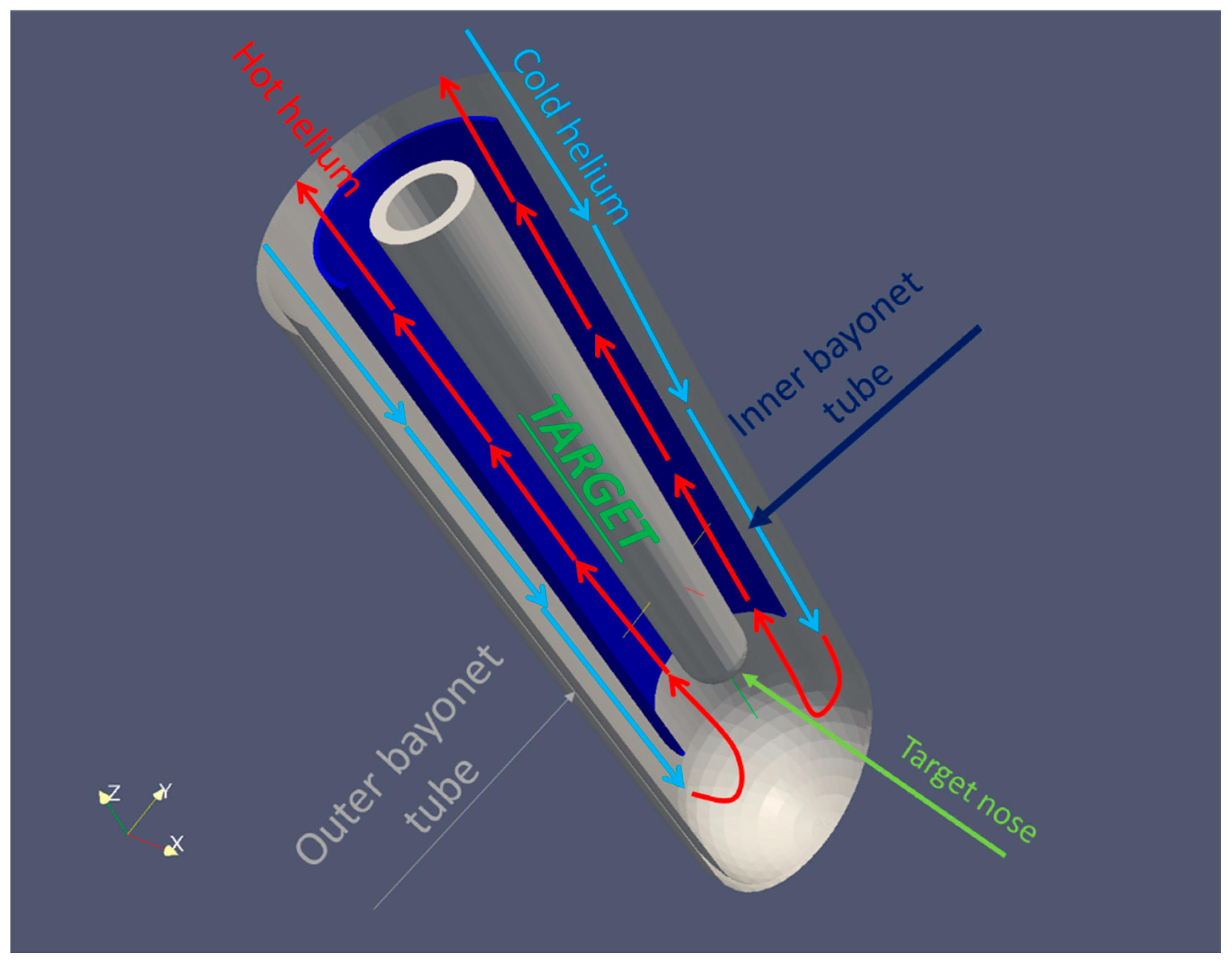
The bayonet tube based heat exchange geometry [19,20] for cooling the target is shown in Figure 1. The flow entering in the volume at the top of the external annulus, flowing downward and going up in the internal annulus between the target and the inner bayonet tube, cooling the target (Figure 2).
- Maximum size of the system: a cylinder with diameter and height equal to 0.12 m and 0.5 m respectively;
- Inlet temperature and operating pressure of the helium equal to 80 °C and 40 bar respectively;
- Maximum temperature of the beryllium equal to 900 °C (the melting point temperature is 1287 °C, and a margin of at least 300 °C was chosen);
- Considering He as the cooling fluid with maximum allowable velocity of 70 m/s.
A preliminary analysis of the cooling system, with the target nominal dimension (Table 1), has been performed by the canonical balance equation with a heat power = 70 kW (and assuming He properties at 40 bar and 80 °C as show in Table 2).
Two potential solutions have been preliminarily proposed:
- = 0.35 kg/s: the ∆T results equal to 38.5 °C and the maximum velocity in the smaller section approximatively equal to 40 m/s;
- = 0.7 kg/s: the ∆T resulting equal to 19.6 °C and the maximum velocity in the smaller section approximatively equal to 70 m/s.
The first step of the performed CFD calculations has demonstrated the inadequacy of the first solution, as detailed in the following section.
2.2. CFD as a Tool for Engineering Verification Calculation
For a deep investigation of the flow field inside the bayonet tube target cooling system, it is necessary to perform a set of numerical simulations via 3D computational tools that allow to explore He flow characteristics inside the domain and identify any critical issues by the point of view of fluid dynamics and thermal field inside solid domain.
As known, the CFD approach consists on the resolution, within a specific calculation mesh and exploiting the Finite Volumes technique (see [21,22] for further details) of the Navier-Stokes system of equations, presented in the following Equations (2)–(4) in a stationary compressible form:
• Continuity:
• Momentum:
• Energy:
where e0 is the total energy, defined as:
Moreover, a conduction model is employed in the heated walls and the equation for the steady-state regime:
Many different CFD codes could be potentially used to perform the analyses reported in this paper. Among those we chose ANSYS-FLUENT® v17.0, a code already widely used and validated for this kind of simulations. A very important step in the CFD calculations process is the preliminary selection by a grid sensitivity analysis. In the following section, the obtained results, and the performed sensitivity analysis are highlighted.
2.3. Preliminary 1D Calculations Comparison and CFD Calculations Assessment
The first step in the performed CFD calculations has been to compare the analytical results with the numerical ones, with the aim to explore the feasibility of the two previously proposed solutions (shortly indicated in the following as = 0.35 and 0.7 kg/s).
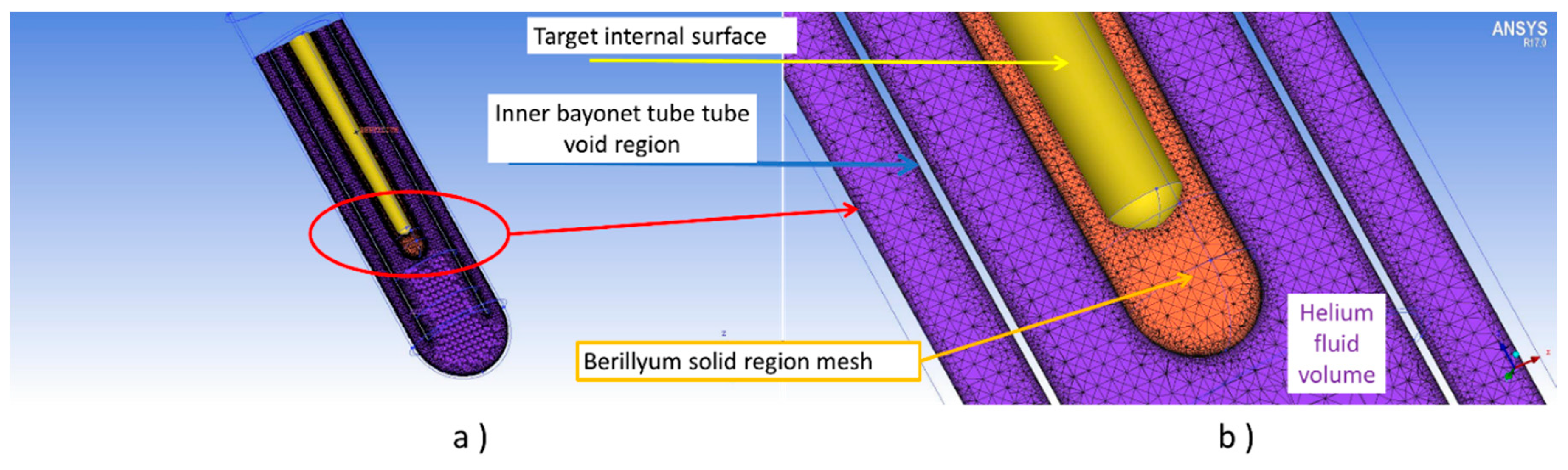
The 3D computational domain includes the fluid volume of the helium cooling fluid and the Be solid region of the target, as show in Figure 3 (where it is possible to see the axial section of the computational grid, in this case composed by approximatively 5 Mnodes). We performed steady-state, incompressible, turbulent calculations. The heat power generated inside the beryllium volume has been considered totally generated on the Beryllium internal surface: the power generation is derived from [23] and the heat power is generated on this surface only for the 70% (this assumption is conservative by the point of view of the maximum temperature reached by the beryllium).
The imposed ANSYS FLUENT Boundary Conditions (BCs) are:
- Mass flow rate at the inlet equal to 0.35 and 0.7 kg/s for the two simulations;
- Inlet temperature equal to 80 °C;
- Pressure outlet at the out of the cooler equal to 0 Pa (relative pressure);
- Coupled heat transfer at the internal target-helium interface;
- Adiabatic conditions for external wall and inner tube;
- The neutronic calculations [12,15] showed that the heat flux is generated non-uniformly inside the volume (the heat flux, obviously, is generated by the protons that impinge on the Be nuclei); for this reason it was decided, as a conservative hypothesis, to impose the flux generation completely on the surface.
Starting from the BCs above reported, the complete stationary heat transfer process has been evaluated, neglecting only the unsteady terms.
Second order Upwind numerical interpolation scheme was used for T, v, k and ε equations; instead, for pressure equation, the Second Order scheme was used.
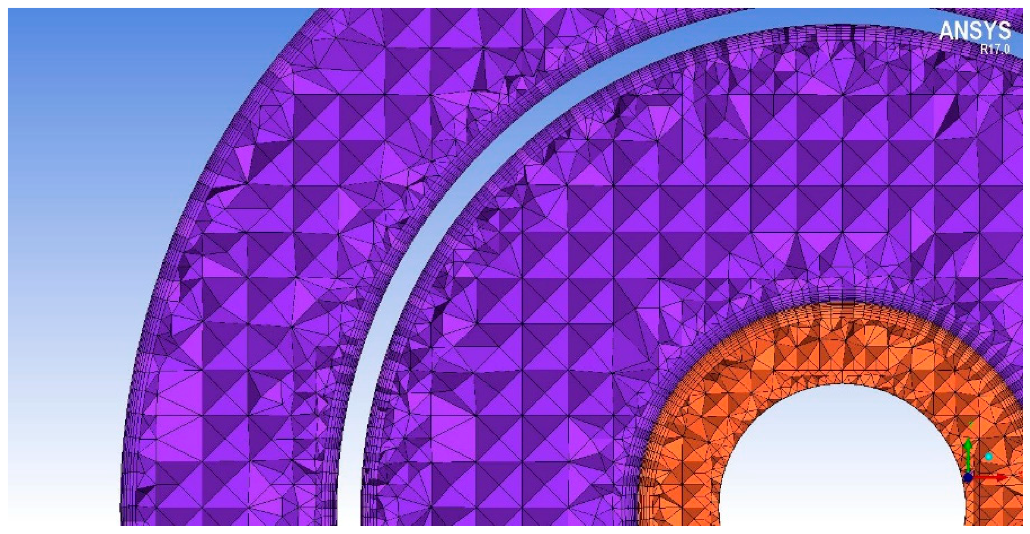
Looking at the numerical turbulence models, for steady-state analyses with SIMPLE pressure-velocity coupling scheme, we chose Realizable k-ε models with standard wall functions, that require y+ < 30 on the first wall node; this value has been obtained by the layer addition shown in Figure 4, having 7 layers with height ratio equal to 1.2 and initial height 1 × 10⁻⁴.
Finally, the beryllium solid body material properties have been assumed constant and reported in Table 3; the helium properties was also assumed constant and equal to those already reported in Table 2.
In the following, the results of a sensitivity mesh analysis were presented; then some 3D calculations with the selected grid are performed: the aim is to investigate primarily the maximum Be temperature reached and the maximum velocity of the helium.
3. Results
3.1. Initial Sensitivity Analysis
In order to avoid grid errors, a grid independency analysis has been performed with about 2.5, 5 and 10 million of nodes; Table 4 reports the percentage errors referred to the 5 Mnodes grid used, where:
- vmax_He is the maximum He velocity inside the fluid domain;
- Tmax_Be is the maximum temperature reached by the solid Be target;
- Δp is the pressure drop inside He, calculated between the inlet and outlet sections;
- Tavg_TARGET is the average temperature of the target-helium interface surface;
- Time/100it is the time required to perform 100 steady iteration (on a Hybrid Intel Phi-Xeon cluster).
Analyzing Table 4 is clearly visible that the 10 Mnodes grid allows to obtain a (relatively) more precise solution than the 5 Mnodes grid but with a considerable increase in calculation time. Furthermore the differences between the two configurations are relatively small. For those reasons the 5 Mnodes grid is the best choice in terms of both accuracy and required computational costs.
With the selected 5 Mnodes grid, a sensitivity analysis on turbulence models has been performed, focusing on k-ε Realizable and k-ω SST turbulence models [24], both with = 0.7 kg/s (Table 5).
The differences between the two turbulence model calculations are relatively small and only for maximum velocity is greater than 5%. The k-ω SST turbulence model overestimates the values of the flow fields with respect to the k-ε Realizable turbulence model, but introduces also a remarkable instability in the calculations, with an unsteady like residuals trend and a longer time required for achieving the convergence (a double number of iterations is required with respect to the k-ε Realizable), although the steady solution is reached anyway avoiding numerical forcing.
In general, in literature there are no detailed data on both experimental and numerical results useful for the present specific set-up; additionally the particular geometry does not allow the use of validated correlations, so considering the relatively small difference in the results and the smaller time required, the following presented simulations have been performed with the k-ε Realizable turbulence model, only sometimes compared with the results obtained by the k-ω SST model.
Due to the goals of this work, which does not propose a deep fluid-dynamic analysis of the flow characteristics (in terms of boundary layer parameters and/or recirculating zones shape and behavior), but rather a partial redesign and optimization of the heat removal system for an ADS target by means of a CFD analysis, this approach results to be acceptable.
3.2. Comparison Among the Proposed Configurations by Analytical Calculations
As already anticipated, two configurations have been proposed, respectively with = 0.35 and 0.7 kg/s.
The CFD results are in good agreement in terms of both He maximum velocity and temperature change, as show in Table 6; instead the maximum Be temperature is, in the case of = 0.35 kg/s, is higher than allowable and very close to the Be melting point. For this reason, the design mass flow rate has been imposed equal to 0.7 kg/s. Figure 5 compare the velocity and temperature fields on an axial section of the domain. It is visible as the higher mass flow rate, increase the velocity but improve also the heat exchange.
Although the solution with = 0.7 Kg/s is sustainable, an optimization of the system with the aim to decrease the maximum velocity of the helium (and consequently to reduce the pressure drops) needs to be performed.
3.3. Optimization of the Proposed Configuration ( = 0.7 m/s)
First of all, some consideration was made in terms of length of the inner tube over the target “nose” (Hbayo in Figure 1).
The extension of this length could allow to the flux to imping the target over the recirculation zones in the initial part of the inner tube. A series of tests with variable Hbayo has been performed and the obtained results are shown in Table 7.
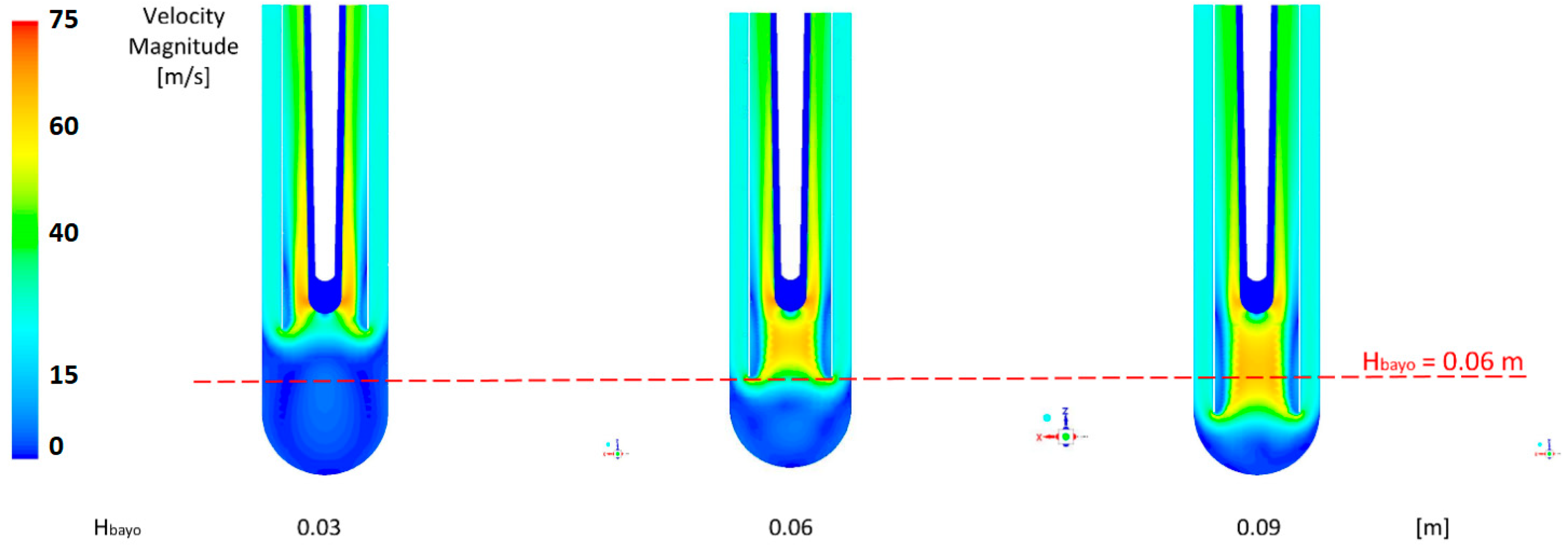
Analyzing the previous Table 7, it is evident that Hbayo = 0.06 m is the best solution, both in terms of Be temperature and He velocity (and associated pressure drops), as shown in Figure 6. The pressure decreases passing from the Hbayo = 0.03 to Hbayo = 0.06 m and subsequently starts to grow again because there are both a higher distributed pressure loss (due to the longer inner tube) and a further effect of acceleration in the final part of the inner tube (due to the beginning of the hemispheric caps of the bayonet outer tube and to a restriction of the section with respect to the Hbayo = 0.03 to Hbayo = 0.06 m cases).
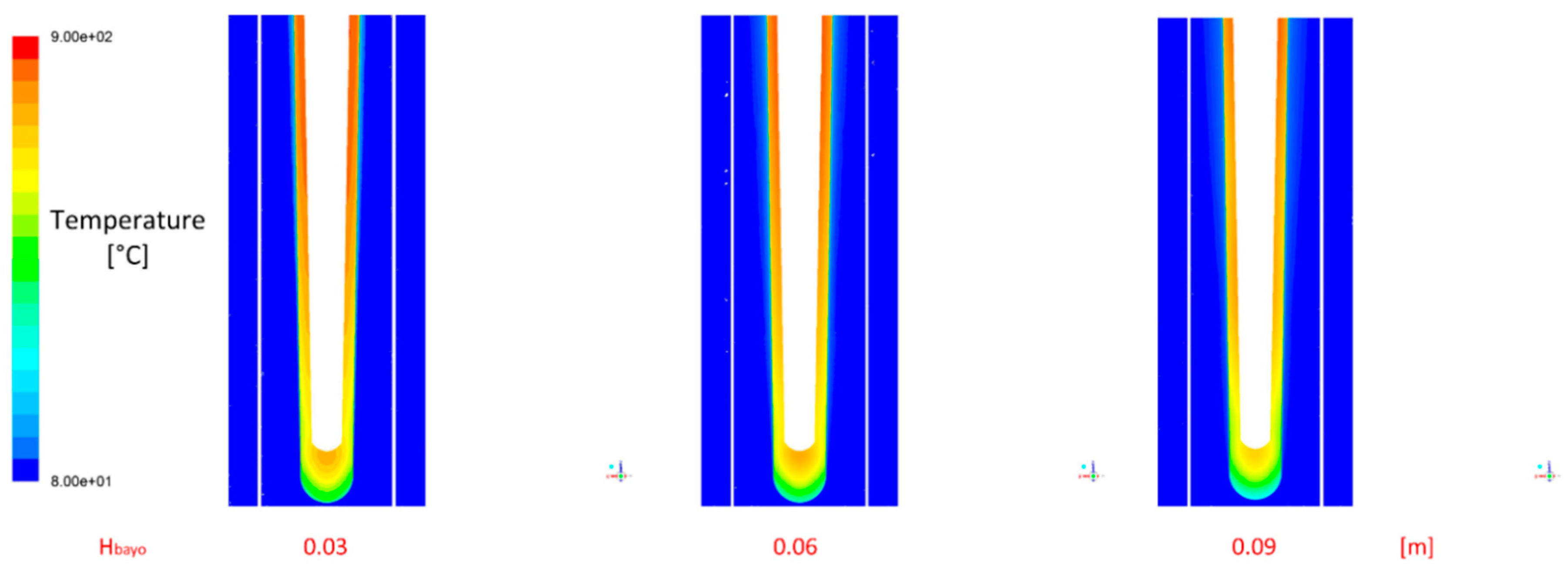
As supposed, the flow impinges the target at the end of the recirculation zones in the initial part of the inner tube downward section, with a reduction of the maximum velocity of around 10%. Furthermore, the temperature peak in the beryllium decreases in the cases Hbayo = 0.06 m and Hbayo = 0.09; in Figure 7 the more efficient heat exchange is shown, with a clear lowering of the average temperature visible from the smoother contours of temperature: this result is mainly due to the more efficient heat exchange in the impingement zone, in turn due to the more developed (with respect to the original case) velocity profiles.
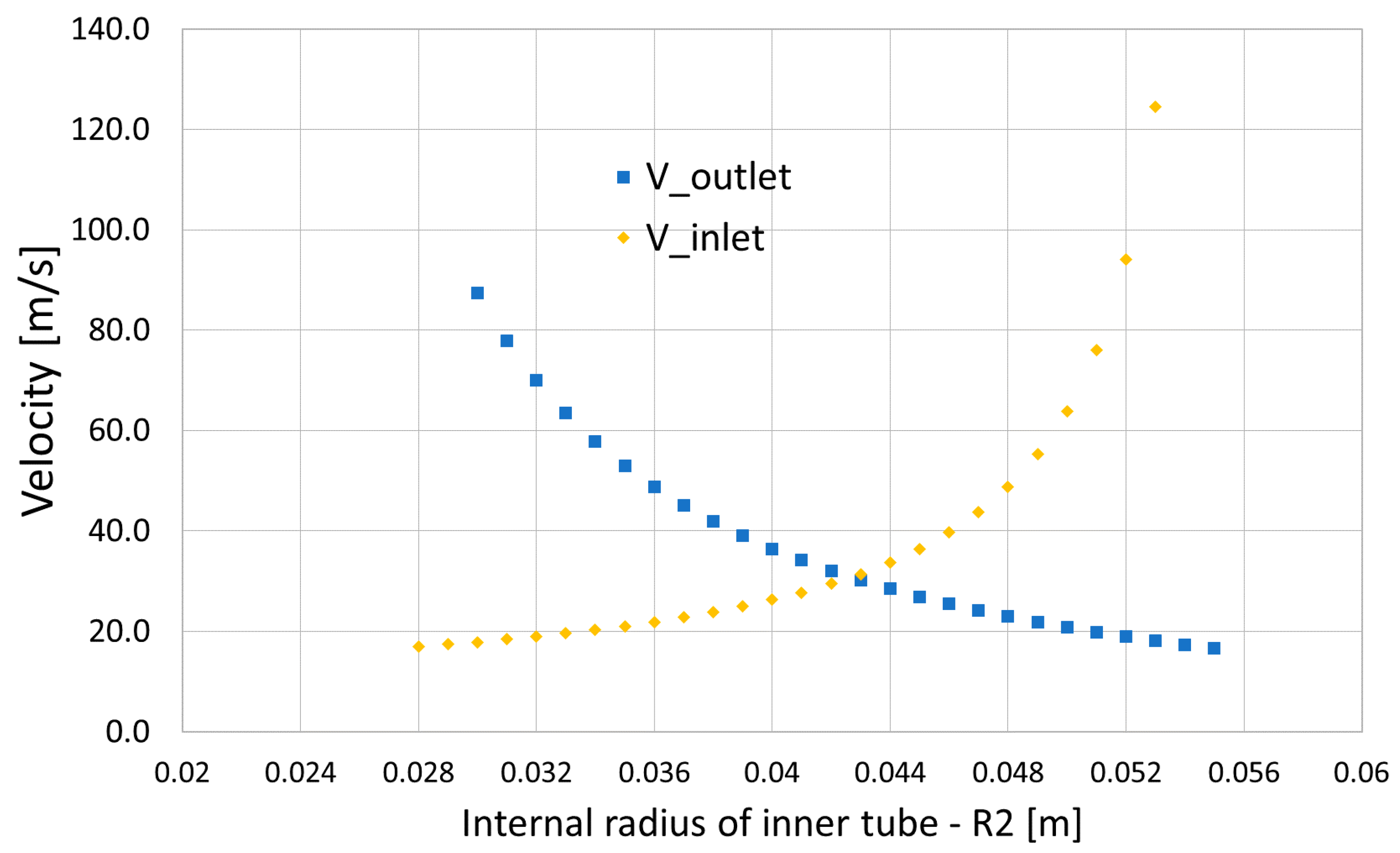
A further optimization has been performed in terms of R2 value (Figure 1): this parameter (the design value is 0.04 m) influences both the inlet and the outlet sections, and consequently the mean velocity of the flow. Figure 8 shows the average value of the inlet and outlet velocity varying R2. On the basis of to the previously shown contours of the velocity magnitude, it is possible to reduce the inlet section area, by incrementing R2 and increasing the mean value of the inlet velocity and potentially decreasing the peak velocity at the outlet. Finally R2 has been chosen equal to 0.048 m, in order to have an increase in the inlet velocity of about 10 m/s but with a decrease of the mean outlet velocity of about 20 m/s. The simulations were conducted assuming Hbayo equal to 0.06 m.
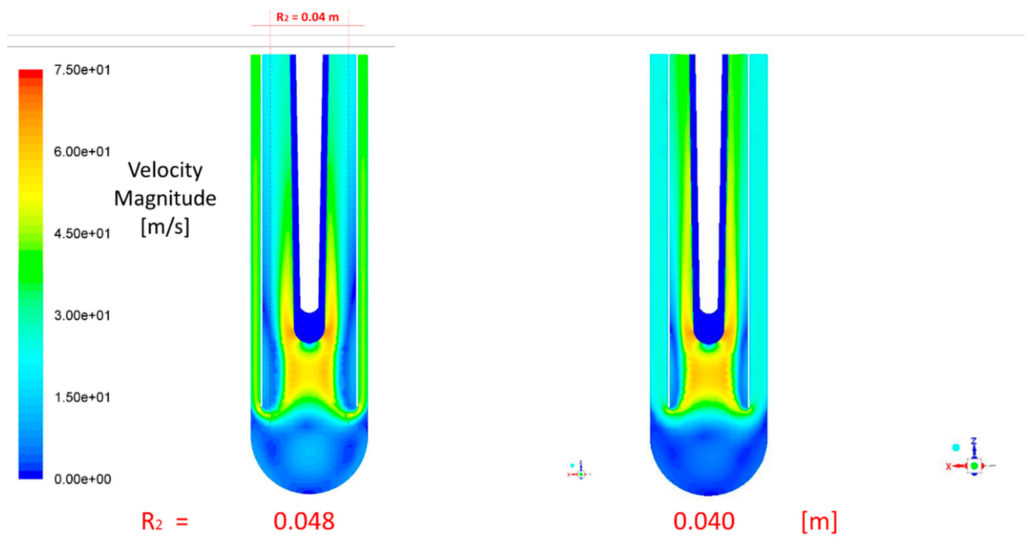
Figure 9 and Figure 10 show the contours of velocity and temperature respectively for original and R2 = 0.048 m cases. The enlargement of the outlet section produces positive effects (decrease of the maximum values) in term of both velocity profile (that results flatter in particular moving towards the outlet section) and of temperature (Table 8).
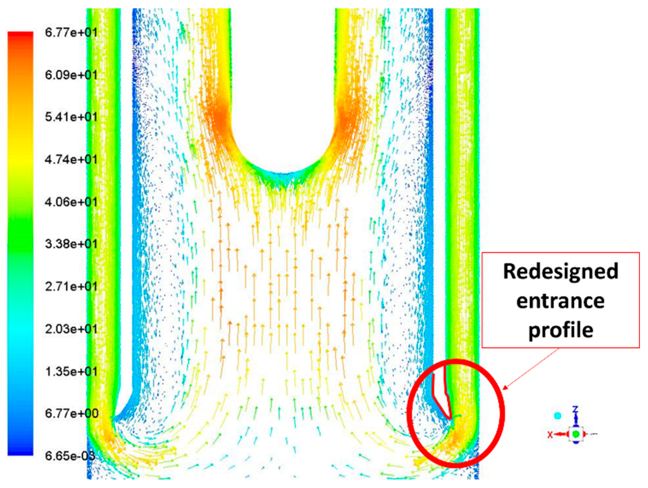
Several other tests with modified parameters have been conducted with the aim of minimizing the recirculation zones at the entrance on the outlet zones (e.g., by increasing the thickness of the tube from 2 to 4 mm as shown in Figure 11), but the obtained improvements are negligible and do not justify the increased constructive complications that they imply.
4. Discussion and Conclusions
Starting from a preliminary design we have partially redesigned the target geometry by means of CFD calculations. Initially some sensitivity analyses have been carried out in order to select the grid dimension and the best applicable turbulence model: a 5 Mnodes grid with the k-ε Realizable turbulence model have finally been chosen.
Then we have optimized the target design in order to minimize the maximum Be temperature and the pressure drops; finally a mass flow rate equal to 0.7 kg/s, Hbayo = 0.06 m and R2 = 0.048 m have been selected.
Additional modifications of other parameter have been also considered but the obtained improvements have not been really significant, so they have been discharged.
The final optimized target design has an increased security margin for what regarding Be melting (reducing maximum temperature from ~900 °C to ~830 °C) and reduces the maximum coolant velocity of about 10% (in term of pressure drops this implies a reduction of about 40%).
Although the main idea of our research is to perform a partial (but realistic and reliable) redesign of the target from an engineering point of view (with a particular focus on the Be cooling) more than a deep thermal-fluid-dynamic analysis of this component, this latter can be a very important potential improvement of the already performed research; so, as future developments we can consider the following:
- The use of standard wall functions will be evaluated more deeply because it could be that, due to the geometry, it should be possible to see some degree of boundary layer separation and swirls and the hottest region is where the boundary layer reattaches and starts to re-develop;
- Because the fluid velocity is relatively high, the viscous heating could also play a non-negligible role, so a specific deep evaluation of this point is foreseen;
- A more deeply analysis the turbulent kinetic energy and/or dissipation rate trends (including more details on the turbulent energy spatial distribution, such as TKE, relative to design parameters and nodalization/grid density, and considerations of optimization methods and/or applied neural network methods) will be performed;
- Further studies and validation activities on the target redesign will be carried on the basis of already performed experimental activities (e.g., [25]);
- The possibility to introduce on the inner part of the bayonet tubes some surface features in order to enhance thermal mixing will be investigating (taking also into account the feasible Be components machinability).
Additionally a full thermo-structural analysis of the new target is foreseen: as known, the spallation target suffers very challenging thermal conditions and the high neutron flux produced by spallation tends to weak the component; as a consequence, the structural integrity needs to be carefully evaluated in order to obtain a lifecycle long enough to avoid too frequent component replacements.
Author Contributions
W.B., G.A. and G.L. conceived and designed the research; W.B. and G.A. performed the calculations and analyzed the data; W.B., G.L. wrote the paper; G.L. supervised the whole research; W.B., G.A. and G.L. revised the paper.
Funding
The research leading to these results has received funding from the European Atomic Energy Community (Euratom)’s Seventh Framework Program FP7/2007–2011 under the Project CHANDA (Grant No. 605203) and has been partially supported by project OCAPIE, funded by Compagnia di San Paolo (Turin, Italy) under contract #9535.
Acknowledgments
The authors want to thank F. Panza, M. Ripani and P. Saracco of INFN for their precious suggestions and support.
Conflicts of Interest
The authors declare no conflict of interest.
Abbreviations
| a | thermal diffusivity, m2/s |
| cp | specific heat, J/kg·K |
| d | diameter, m |
| e | rib height, m |
| f | friction coefficient |
| H | channel height, m |
| L | length, m |
| K | turbulent kinetic energy, m2/s2 |
| Nu | Nusselt number |
| p | rib pitch, m |
| P | pressure, Pa |
| PEC | performance evaluation criteria index |
| PP | pumping power, W |
| Pr | Prandtl number |
| q | heat flux, W/m2 |
| Re | Reynolds number |
| s | channel thickness, m |
| T | temperature, K |
| T* | dimensionless temperature, T* = T/Tbulk |
| u | velocity component, m/s |
| W | channel width, m |
| w | rib width, m |
| x, y | spatial coordinates, m |
| δ | Kronecher delta function |
| λ | thermal conductivity, W/m·K |
| μ | dynamic viscosity, Pa·s |
| ν | kinematic viscosity, m2/s |
| ρ | density, kg/m3 |
| σ | turbulent Prandtl number |
| τ | wall shear stress, kg/m2 |
| ω | rate of dissipated turbulent kinetic energy |
References
- Cerullo, N.; Lomonaco, G. Generation IV reactor designs, operation and fuel cycle. In Nuclear Fuel Cycle Science and Engineering; Crossland, I., Ed.; Woodhead Publishing: Cambridge, UK, 2012; pp. 333–395. [Google Scholar]
- Borreani, W.; Alemberti, A.; Lomonaco, G.; Magugliani, F.; Saracco, P. Design and selection of innovative primary circulation pumps for GEN-IV lead fast reactors. Energies 2017, 10, 2079. [Google Scholar] [CrossRef]
- Castelliti, D.; Lomonaco, G. A preliminary stability analysis of MYRRHA Primary Heat Exchanger two-phase tube bundle. Nuclear Eng. Des. 2016, 305, 179–190. [Google Scholar] [CrossRef]
- Lizzoli, M.; Borreani, W.; Devia, F.; Lomonaco, G.; Tarantino, M. Preliminary CFD Assessment of an Experimental Test Facility Operating with Heavy Liquid Metals. Sci. Technol. Nuclear Install. 2017, 2017, 1949673. [Google Scholar] [CrossRef]
- Lomonaco, G.; Frasciello, O.; Osipenko, M.; Ricco, G.; Ripani, M. An intrinsically safe facility for forefront research and training on nuclear technologies–Burnup and transmutation. Eur. Phys. J. Plus 2014, 129. [Google Scholar] [CrossRef]
- Abderrahim, H.A. Future advanced nuclear systems and the role of MYRRHA as a waste transmutation R&D facility. In Proceedings of the International Conference on Fast Reactors and related fuel cycles: Safe technology and sustainable scenarios, Paris, France, 4–7 March 2013. [Google Scholar]
- Billebaud, A.; Brissot, R.; Heuer, D.; Kerveno, M.; le Brun, C.; Liatard, E.; Loiseaux, J.M.; Meplan, O.; Merle, E.; Perdu, F.; et al. The MUSE-4 experiment: prompt reactivity and neutron spectrum measurements. In Proceedings of the PHYSOR 2002, International Conference on the New Frontiers of Nuclear Technology Reactor Physics, Safety and High-Performance Computing, Seoul, Korea, 7–10 October 2002. [Google Scholar]
- Billebaud, A.; Baeten, P.; Abderrahim, H.A.; Ban, G.; Baylac, M.; Bergmans, G.; Bondoux, D.; Bouvier, J.; Chabod, S.; de Conto, J.M.; et al. The GUINEVERE Project for Accelerator Driven System Physics. In Proceedings of the International Conference GLOBAL 2009, The Nuclear Fuel Cycle: Sustainable Options & Industrial Perspectives, Paris, France, 9 September 2009. [Google Scholar]
- Gohar, Y.; Smith, D.L. YALINA Facility a Sub-Critical Accelerator-Driven System (ADS) for Nuclear-Energy Research Facility Description and an Overview of the Research Program (1997–2008); Technical Report for Argonne National Laboratory; Argonne National Laboratory: Argonne, IL, USA, 28 April 2010. [Google Scholar]
- Gohar, Y.; Bolshinsky, I.; Karnaukhov, I. KIPT accelerator-driven system design and performance. In Proceedings of the Second International Workshop on Technology and Components of Accelerator-driven Systems, Nantes, France, 21–23 May 2013. [Google Scholar]
- Kochetkov, A.; Vittiglio, G.; Wagemans, J.; Uyttenhove, W.; Krása, A.; Hernandez, J. The Lead-Based VENUS-F Facility: Status of the FREYA Project. Eur. Phys. J. WOC 2016, 106, 06004. [Google Scholar] [CrossRef] [Green Version]
- Panza, F.; Firpo, G.; Lomonaco, G.; Osipenko, M.; Ricco, G.; Ripani, M.; Viberti, G.M. A low power ADS for transmutation studies in fast systems. EPJ Nuclear Sci. Technol. 2017, 3. [Google Scholar] [CrossRef]
- Lomonaco, G.; Borreani, W.; Bruzzone, M.; Chersola, D.; Firpo, G.; Osipenko, M.; Palmero, M.; Panza, F.; Ripani, M.; Saracco, P.; et al. Initial thermal-hydraulic assessment by OpenFOAM and FLUENT of a subcritical irradiation facility. Therm. Sci. Eng. Prog. 2018, 6, 447–456. [Google Scholar] [CrossRef]
- Mansani, L.; Bruzzone, M.; Frambati, S.; Reale, M. An intrinsically safe facility for forefront research and training on nuclear technologies—General description of the system. Eur. Phys. J. Plus 2014, 129. [Google Scholar] [CrossRef]
- Panza, F.; Borreani, W.; Firpo, G.; Lomonaco, G.; Osipenko, M.; Palmero, M.; Ricco, G.; Ripani, M.; Saracco, P.; Viberti, C.M. An ADS irradiation facility for fast and slow neutrons. Eur. Phys. J. Plus 2018. under review. [Google Scholar]
- Ciotti, M. An intrinsically safe facility for forefront research and training on nuclear technologies–Target profile optimization. Eur. Phys. J. Plus 2014, 129. [Google Scholar] [CrossRef]
- Osipenko, M.; Ripani, M.; Ricco, G.; Celentano, A.; Viberti, C.M.; Alba, R.; Schillaci, M.; Cosentino, G.; del Zoppo, A.; di Pietro, A.; et al. An intrinsically safe facility for forefront research and training on nuclear technologies–Neutron yield from Be. Eur. Phys. J. Plus 2014, 129. [Google Scholar] [CrossRef]
- Borreani, W.; Bruzzone, M.; Chersola, D.; Firpo, G.; Lomonaco, G.; Palmero, M.; Panza, F.; Ripani, M.; Saracco, P.; Viberti, C.M. Preliminary thermal-fluid-dynamic assessment of an ADS irradiation facility for fast and slow neutrons. Int. J. Heat Technol. 2017, 35, 186–190. [Google Scholar] [CrossRef]
- Rozzia, D.; Toti, A.; Tarantino, M.; Gramiccia, L.; Vitale Di Maio, D.; Giannetti, F. Double-Wall Bayonet Tube Steam Generator for LFR Application. Preliminary Characterization; ENEA Report RdS/2011/50; ENEA: Rome, Italy, September 2011. [Google Scholar]
- Ma, T.; Zeng, M.; Ji, Y.; Zhu, H.; Wang, Q. Investigation of a novel bayonet tube high temperature heat exchanger with inner and outer fins. Int. J. Hydrog. Energy 2011, 36, 3757–3768. [Google Scholar] [CrossRef]
- Hirsch, C. Numerical computation of internal & and external flow: The Fundamentals of Computational Fluid Dynamics, 2nd ed.; Butterworth-Heinemann: Oxford, UK, 2007; ISBN 9780750665940. [Google Scholar]
- Borreani, W. Thermo-Hydraulic Analysis by Different CFD Codes of Some Components of the Primary System of Gen-IV Lead-Cooled Demonstrator ALFRED. Ph.D. Thesis, DIME, University of Genova, Genoa, Italy, March 2017. [Google Scholar]
- Viberti, C.M.; Ricco, G. An intrinsically safe facility for forefront research and training on nuclear technologies–Core design. Eur. Phys. J. Plus 2014, 129. [Google Scholar] [CrossRef]
- Menter, F.R. Zonal Two Equation k-ω Turbulence Models for Aerodynamic Flows. In Proceedings of the 23rd Fluid Dynamics, Plasmadynamics, and Lasers Conference, Fluid Dynamics and Co-located Conferences, AIAA Paper 93–2906, Orlando, FL, USA, 6–9 July 1993. [Google Scholar] [CrossRef]
- Haga, K.; Takeda, Y.; Bauer, G.; Guttek, B. Flow Study on the ESS target water model. In Proceedings of the ICANS XIV, 14th Meeting of the International Collaboration on Advanced Neutron Sources, Starved Rock Lodge, Utica, IL, USA, 14–19 June 1998. [Google Scholar]
Figure 1.
Geometry of the cooling target system.

Figure 2.
Target Bayonet tube scheme of operation.

Figure 3.
Computational domain with indications of the zones and an axial view of the mesh. (a) Axial view of the computational domain; (b) Indications of the zones of the mesh.
Figure 3.
Computational domain with indications of the zones and an axial view of the mesh. (a) Axial view of the computational domain; (b) Indications of the zones of the mesh.

Figure 4.
Layer additions near the wall in the fluid domain.

Figure 5.
Comparison between mass flow rate 0.35 and 0.7 kg/s case velocity flow field.
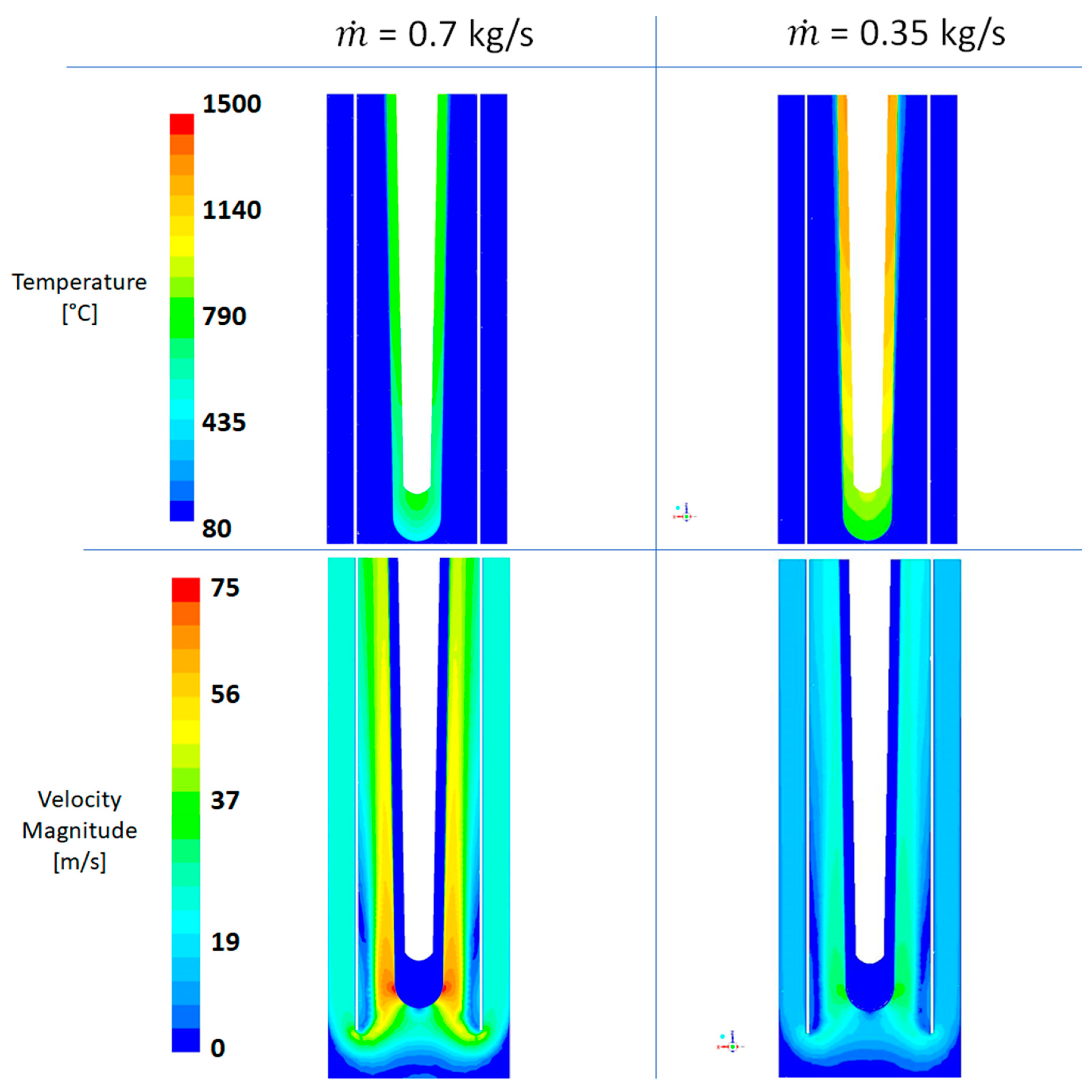
Figure 6.
Comparison of velocity fields for Hbayo equal to 0.03, 0.06 and 0.09 m.

Figure 7.
Comparison of temperature fields for Hbayo equal to 0.03, 0.06 and 0.09 m.

Figure 8.
Value of the inlet and outlet velocities vs. R2 radius values.

Figure 9.
Velocity fields comparison for R2 equal to 0.04 and 0.048 m.

Figure 10.
Temperature field comparison for R2 equal to 0.048 and 0.040 m.
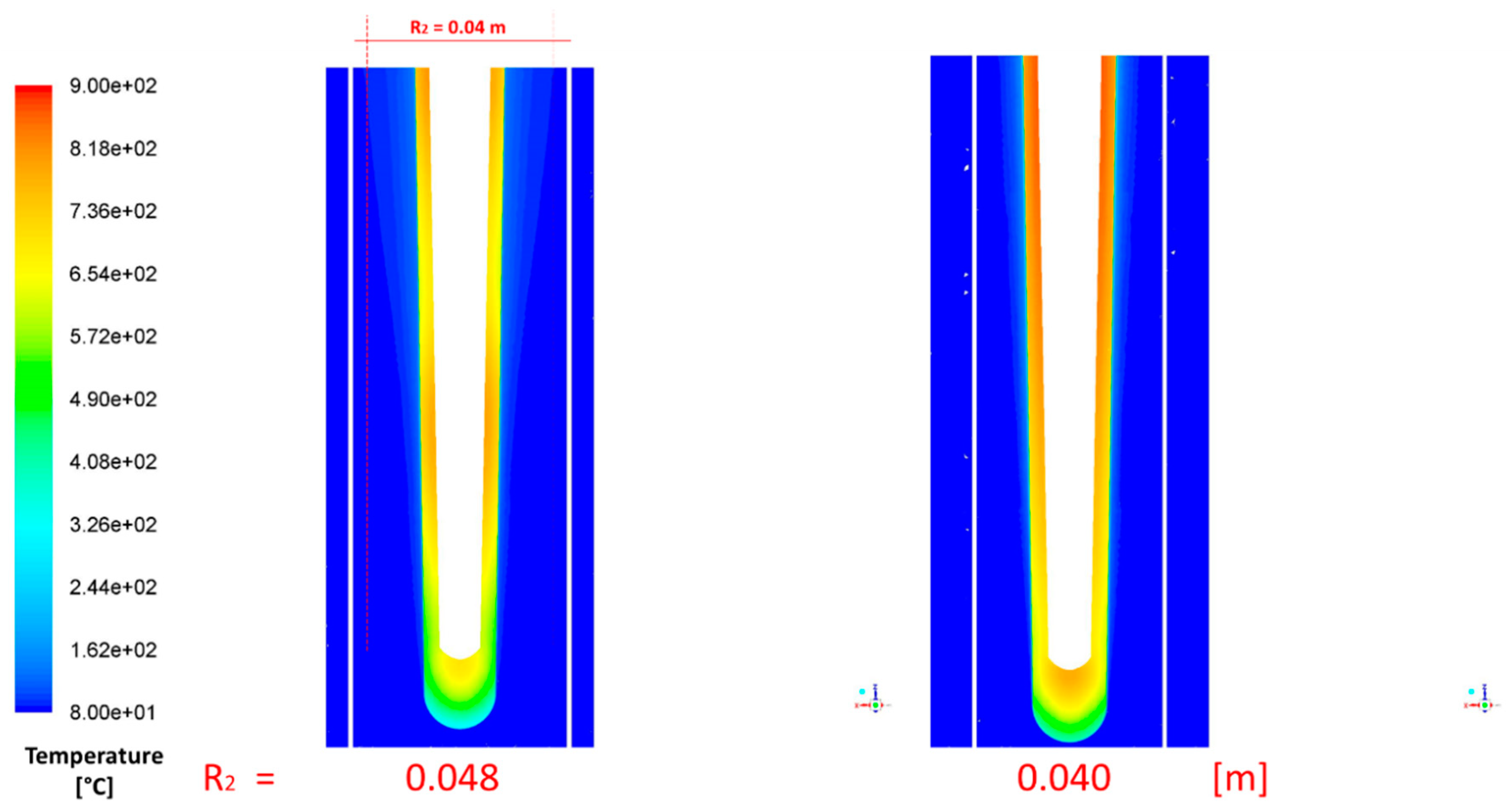
Figure 11.
Redesigned entrance profile (velocity vector shown there are negligible improvements in terms of recirculation zones reduction).
Figure 11.
Redesigned entrance profile (velocity vector shown there are negligible improvements in terms of recirculation zones reduction).


Table 1.
Nominal target dimension (see Figure 1).
Table 1.
Nominal target dimension (see Figure 1).
| Geometrical Dimensions | (m) |
|---|---|
| H1 | 0.5 |
| H2 | 0.36 |
| R1 | 0.06 |
| R2 | 0.04 |
| Hbayo | 0.06 |
Table 2.
He properties at 40 bar and 80 °C.
| Property | Value |
|---|---|
| ρ (kg/m3) | 5.0878 |
| cp (kJ/kg·K) | 5189.6 |
| k (W/m·K) | 0.184 |
| µ (Pa·s) | 2.33 × 10⁻⁵ |
Table 3.
Beryllium properties.
| Property | Value |
|---|---|
| ρ (kg/m3) | 1848 |
| cp (J/kg·K) | 1825 |
| k (W/m·K) | 201 |
Table 4.
Sensitivity analysis of grid size (5 Mnodes grid is the reference value).
| Mnodes | ~2, 5 | ~10 |
|---|---|---|
| Vmax_He | −5.0% | 1.9% |
| Tmax_Be | −4.3% | 1.2% |
| Δp | −2.0% | 1.8% |
| Tavg_TARGET | −6.1% | 0.1% |
| Time/100it | ~−20% | ~+70% |
Table 5.
Sensitivity analysis on turbulence models.
| Turbulence Models | k-ε Realizable | k-ω SST | diff. (%) |
|---|---|---|---|
| Vmax_He | 69.3 | 74.8 | 8% |
| Tmax_Be | 849.1 | 859.8 | 1% |
| Δp | 6196.1 | 6473.0 | 4% |
| Tavg_TARGET | 660.1 | 686.7 | 4% |
Table 6.
Comparison of macroscopic flow fields parameter in the case of mass flow rate equal to 0.35 and 0.7 kg/s.
Table 6.
Comparison of macroscopic flow fields parameter in the case of mass flow rate equal to 0.35 and 0.7 kg/s.
| 0.35 kg/s | 0.7 kg/s | Diff. (%) | |
|---|---|---|---|
| Vmax_He | 41.3 | 74.8 | 44.8% |
| Tmax_Be | 1297.6 | 859.8 | −50.9% |
| Δp | 1683.6 | 6473.0 | 73.0% |
| Tavg_TARGET | 1100.7 | 686.7 | −60.3% |
Table 7.
Comparison for Hbayo equal to 0.03, 0.06 and 0.09 m.
| Hbayo (m) | 0.03 | 0.06 | 0.09 |
|---|---|---|---|
| Vmax_He | 74.8 | 67.6 | 68.3 |
| Tmax_Be | 859.8 | 831.1 | 868.1 |
| Δp | 6473.0 | 6287.9 | 6438.0 |
| Tavg_TARGET | 686.7 | 659.5 | 668.4 |
Table 8.
Comparison of R2 = 0.048 m and original case.
| R2 (m) | 0.048 | 0.04 |
|---|---|---|
| Vmax_He | 66.1 | 67.6 |
| Tmax_Be | 807.9 | 831.1 |
| Δp | 3940.3 | 6287.9 |
| Tavg_TARGET | 618.1 | 659.5 |
© 2018 by the authors. Licensee MDPI, Basel, Switzerland. This article is an open access article distributed under the terms and conditions of the Creative Commons Attribution (CC BY) license (http://creativecommons.org/licenses/by/4.0/).
Share and Cite
MDPI and ACS Style
Lomonaco, G.; Alessandroni, G.; Borreani, W. Partial Redesign of an Accelerator Driven System Target for Optimizing the Heat Removal and Minimizing the Pressure Drops. Energies 2018, 11, 2090. https://doi.org/10.3390/en11082090
AMA Style
Lomonaco G, Alessandroni G, Borreani W. Partial Redesign of an Accelerator Driven System Target for Optimizing the Heat Removal and Minimizing the Pressure Drops. Energies. 2018; 11(8):2090. https://doi.org/10.3390/en11082090
Chicago/Turabian StyleLomonaco, Guglielmo, Giacomo Alessandroni, and Walter Borreani. 2018. "Partial Redesign of an Accelerator Driven System Target for Optimizing the Heat Removal and Minimizing the Pressure Drops" Energies 11, no. 8: 2090. https://doi.org/10.3390/en11082090
Note that from the first issue of 2016, this journal uses article numbers instead of page numbers. See further details here.