Analysis and Design of a Compound-Structure Permanent-Magnet Motor for Hybrid Electric Vehicles

1
State Key Laboratory of Power Transmission Equipment & System Security and New Technology, Chongqing University, Chongqing 400044, China
2
China North Vehicle Research Institute, Beijing 100072, China
3
Department of Electrical Engineering, Harbin Institute of Technology, Harbin 150080, China
*
Author to whom correspondence should be addressed.
Energies 2018, 11(8), 2156; https://doi.org/10.3390/en11082156
Submission received: 19 July 2018
/
Revised: 5 August 2018
/
Accepted: 9 August 2018
/
Published: 17 August 2018
(This article belongs to the Special Issue Demand Response in Electricity Markets)
Abstract
:On the basis of the excellent driving force demand of hybrid electric vehicles (HEVs), this paper studies the torque property of the compound-structure permanent-magnet motor (CSPM motor) used for HEVs, which is influenced by magnetic field oversaturation and variable nonlinear parameters. Firstly, the system configuration of HEVs based on CSPM motor and its working mode are introduced. Next, the state equation of CSPM motor in three-phase stationary coordinate system is proposed in order to investigate its torque performance; then, the factors affecting the output torque are gained. Finite element method (FEM)-based electromagnetic parameters analysis and design is carried out, to raise the output torque and reduce the torque ripple of CSPM motor. Besides, optimized design parameters are used to establish the FEM model, and the simulation results of electromagnetic performances for the CSPM motor before and after optimization are given to verify the rationality of optimization.
1. Introduction
At present, in the face of the global energy crisis and environmental pollution problems, hybrid electric vehicles (HEVs), as an environmentally friendly choice, have been developed rapidly. The HEVs use a dual-rotor motor as a power distribution device, together with an advanced control system, to make the two power units, i.e., the internal combustion engine (ICE) and battery cooperate to achieve low energy consumption and low pollution [1]. Nowadays, power distribution devices mainly contain electric variable transmission (EVT), a compound-structure permanent-magnet motor (CSPM motor), a switched reluctance motor (SRM), magnetic-geared EVT, and the radial magnetic-field modulated brushless double-rotor machine (RMFM-BDRM), whose performances directly affect the quality of HEVs [2,3,4,5,6].
The CSPM motor as an electromechanical energy conversion device with a dual-rotor structure has been widely utilized in industry, for instance in HEVs, due to the high torque density, wide speed range, and long working life. The CSPM motor can achieve different energy flows in HEVs and transmit torque to drive the vehicle. However, it also has the problem of electromagnetic coupling, which affects the driving force and running stability. To achieve electromagnetic decoupling in the CSPM motor, the following research has been carried out by national and international scholars and researchers [7,8,9,10,11,12]: (1) studying the working principle of the CSPM motor under compound excitation source using the magnetic circuit mathematical model and analyzing its inductance parameters based on the finite element method (FEM); (2) studying the influence of structural parameters on the coupling degree to optimize the electromagnetic structure of the CSPM motor. Different electromagnetic structure schemes are designed and compared, such as the different permanent magnet sizes, outer rotor yoke thicknesses, stator winding armature reaction, and material utilization ratios; (3) studying the different topology schemes of the CSPM motor, then the electromagnetic coupling degree, torque density and heat dissipation are compared to meet the different requirements in the hybrid power system; (4) establishing the magnetic network calculation model, together with the Matlab software to analyze the parameters of CSPM motor. The influence of structural parameters on the electromagnetic coupling degree is explored in order to optimize the structural parameters; (5) studying the torque control strategy of the CSPM motor based on the mathematical model and load characteristics, to realize independent control of the output speed and torque.
To meet the demands of the large traction and smooth operation of HEVs, the aim of this paper is to increase the output torque and reduce the torque ripple of the CSPM motor. The system configuration of HEVs based on the CSPM motor and its working mode are presented in Section 2. The mathematical model of the CSPM motor is derived in Section 3 to analyze the factors affecting torque performance. In Section 4, the electromagnetic parameters analysis and the optimization of the CSPM motor are carried out, adopting 2D FEM to estimate the effects of different structure sizes on torque properties. Appropriate design parameters are used to establish the FEM model, and the performance of the CSPM motor before and after optimization is compared in Section 5. The simulation results prove the reasonableness and validity of electromagnetic parameters optimization.
2. System Configuration and Working Mode
2.1. System Configuration
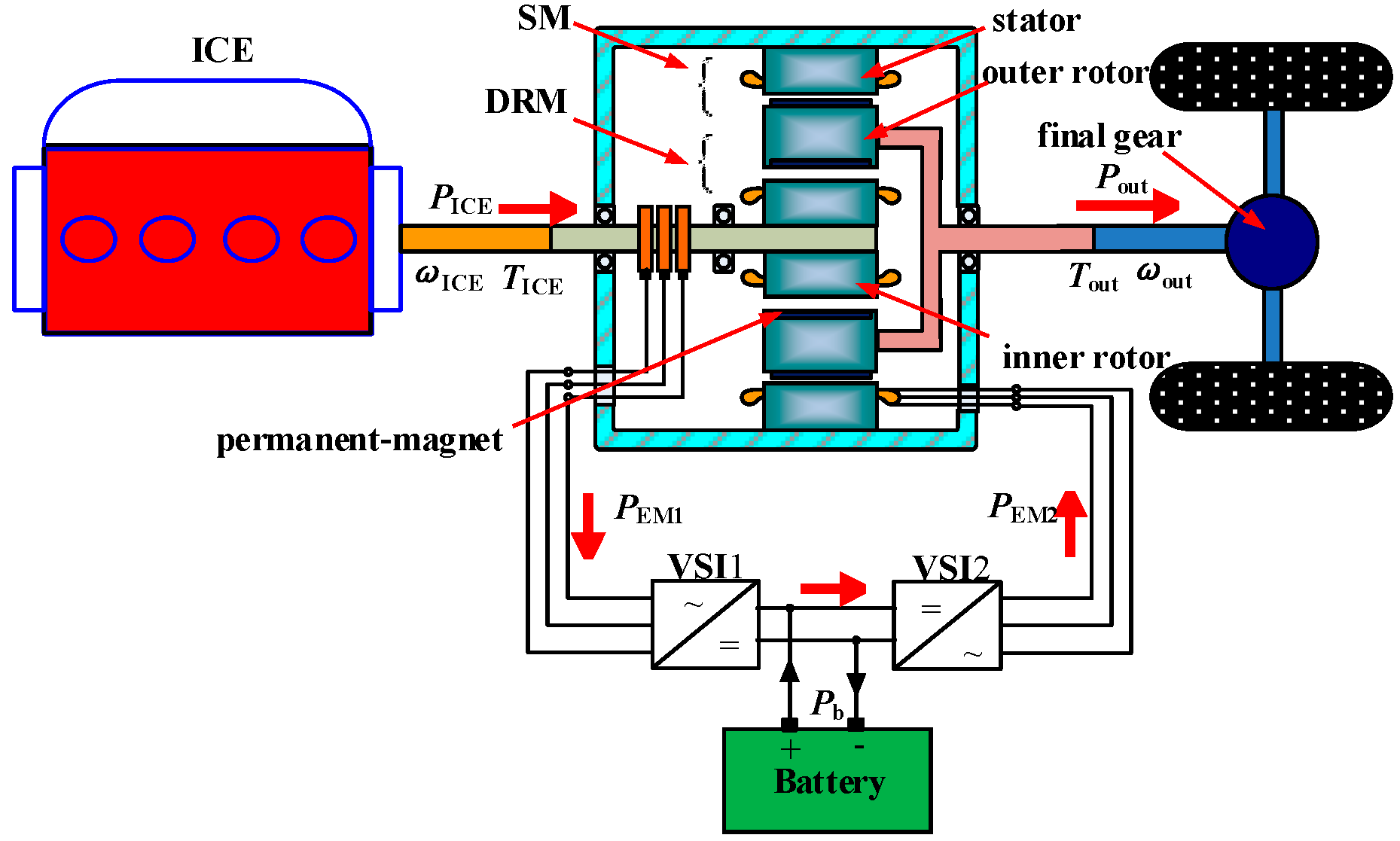
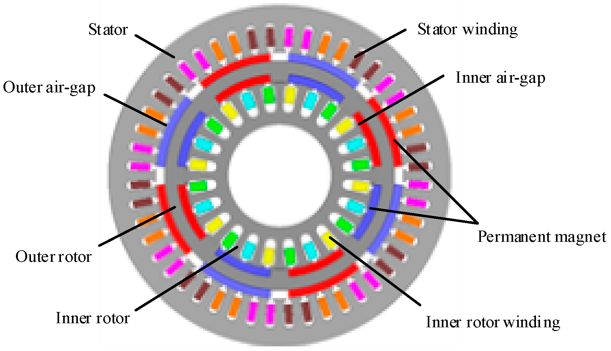
Figure 1 is the diagram of HEVs based on CSPM motor. The CSPM motor is located between the ICE and HEVs, which consist of a stator with three phase winding, an inner rotor with three phase winding, and an outer rotor with two layers of permanent magnets. The inner rotor connects with ICE, and the outer rotor links with the HEVs. The permanent magnet inside and outside the outer rotor is embedded and surface-mounted, separately. The three-phase windings of inner rotor connect with the three collector rings on the rotating shaft, and the electric energy is derived by the electric brush. The stator and outer rotors with their outside permanent magnets constitute the stator machine (SM). The inner rotor and the outer rotor with inside permanent magnets comprise the double-rotor machine (DRM). Both the SM and DRM can be regarded as a permanent magnet synchronous motor.
SM and DRM are arranged in radial direction, which can regulate the speed and torque of ICE at the same time to make it run in the high efficiency area furthest. Therefore, the fuel efficiencies are improved, and exhaust emissions of HEVs are reduced. The maximum output power of this transmission is the sum power of the ICE and battery. So, under the same maximum output power, the power level of the ICE and battery is less than the traditional vehicles and battery-based EVs.
2.2. Working Mode
With the suitable control strategies, the working mode of HEVs based on CSPM motor can be switched in different road conditions to realize the function of idle stop, power compensation, and braking energy feedback, etc. The working mode of the CSPM motor drive system can be divided into pure electric mode, hybrid mode, braking mode, and over-speed mode.
2.2.1. Pure Electric Mode
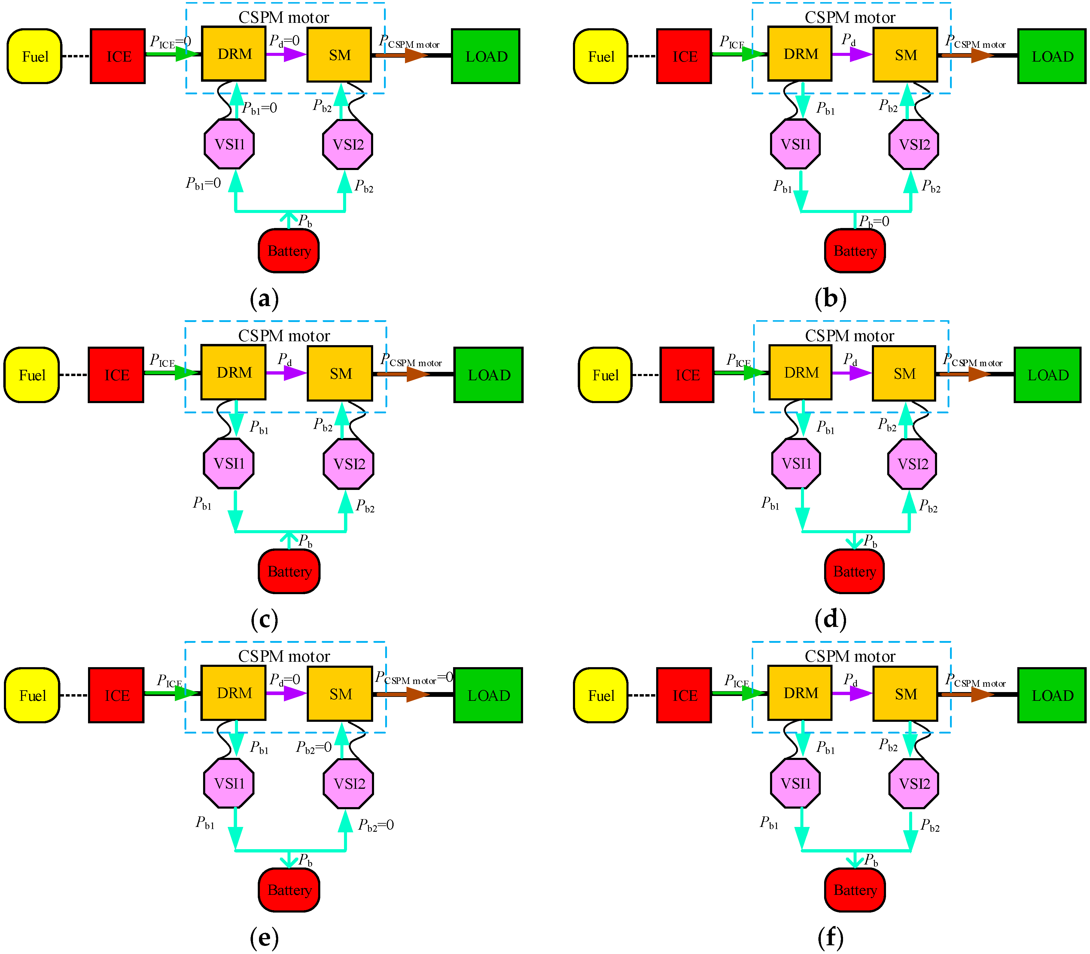
The HEVs require low power at the start stage, and the efficiency of ICE is low when running at low speed or low-power output. Therefore, to reduce fuel consumptions and exhaust emissions, the CSPM motor works in the pure electric mode, which is only driven by SM; the power flow process is shown in Figure 2a. When SM does not meet the driving force requirement, the DRM also runs in the electric state. At this time, PICE = 0, Pb1 ≠ 0, and Pd ≠ 0.
2.2.2. Hybrid Mode
(1) CVT mode
This is the main working mode of HEVs based on CSPM motor. The input mechanical energy of ICE is equal to the output mechanical energy of CSPM motor. As the speed or the demand power of HEVs increase to the point where the battery is unable to supply, the ICE starts, as shown in Figure 2b. When the speed of ICE is less than that of HEVs, the DRM is in electric state, and the SM is in generation state to compensate for the required power. When the speed of ICE is larger than that of HEVs, the DRM is in generation state. The output mechanical energy of ICE is converted into electric energy via DRM and transferred to the stator by the air-gap magnetic field to drive the vehicle directly. The DRM transfers the ICE’s torque to the outer rotor and compensates the speed difference between the ICE and load. The SM compensates the ICE’s torque according to the road load.
(2) Auxiliary Power Mode
In CVT mode, only the ICE provides power to drive the vehicle. If the speed increases further, the output power of CSPM motor will be greater than the input power of ICE. At this time, the battery, which is charged by the output power of DRM, will provide the electrical energy to SM to improve its output power, which is given in Figure 2c. The control system should offer energy management strategy to control the energy storage device.
(3) Driving and Parking Generation Mode
When the SOC of battery is lower than the minimum threshold, it is necessary to increase or decrease the output power of ICE and convert the excess energy into electrical energy to charge the battery. The HEVs have driving or parking power generation mode. In the driving generation mode, the ICE provides mechanical energy for DRM to generate electricity. A part of the electric energy is transmitted to SM through the voltage source inverter to finish CVT mode, and the rest is charging the battery, as shown in Figure 2d. In the parking power generation mode, only the DRM operates in power generation mode to charge the battery, as shown in Figure 2e.
2.2.3. Braking Mode
(1) Electric Braking Mode
When the HEVs need to decelerate or break, and the SOC of battery does not exceed the maximum threshold, energy recovery can be achieved by SM braking to generate electricity to improve the utilization rate of energy. The SM and DRM are in the power generation state to charge the battery, which is given in Figure 2f. The battery energy management strategy should be combined to prevent the excessive charging current. The required braking torque is determined according to the brake pedal depth. When the maximum braking torque provided by SM meets the demand braking torque, the reference instruction is equal to the required braking torque; when not satisfied, part of braking torque is provided by SM; the rest is provided by the mechanical brake torque of the driver stepping on the brake pedal.
(2) Regenerative Braking Mode
2.2.4. Over-Speed Mode
Both SM and DRM are in the electric state, and the output power of battery is large, as shown in Figure 2i. The corresponding energy management strategy must be applied to charge the battery when the SOC is lower than the minimum threshold.
It can be seen in Figure 2 that the HEVs based on CSPM motor have various changeable energy flows between SM and DRM, due to the coupling effect between them. This can choose a proper working mode during operation, which is regarded as an advantage of HEVs. However, when the magnetic field is supersaturated, it will change the inductance parameters and increase iron losses, lead to the back EMF or current waveform distortion, which produces torque ripple and weakens output torque [13]. Therefore, the electromagnetic structure of CSPM motor needs to be optimized using mathematical model and electromagnetic analysis method in the next part, to realize the magnetic field decoupling of DRM and SM. Then, the suitable dynamic allocation strategy for each mode will be easier to make to improve the switching operability between different working modes.
3. State Equation in Three-Phase Stationary Coordinate System
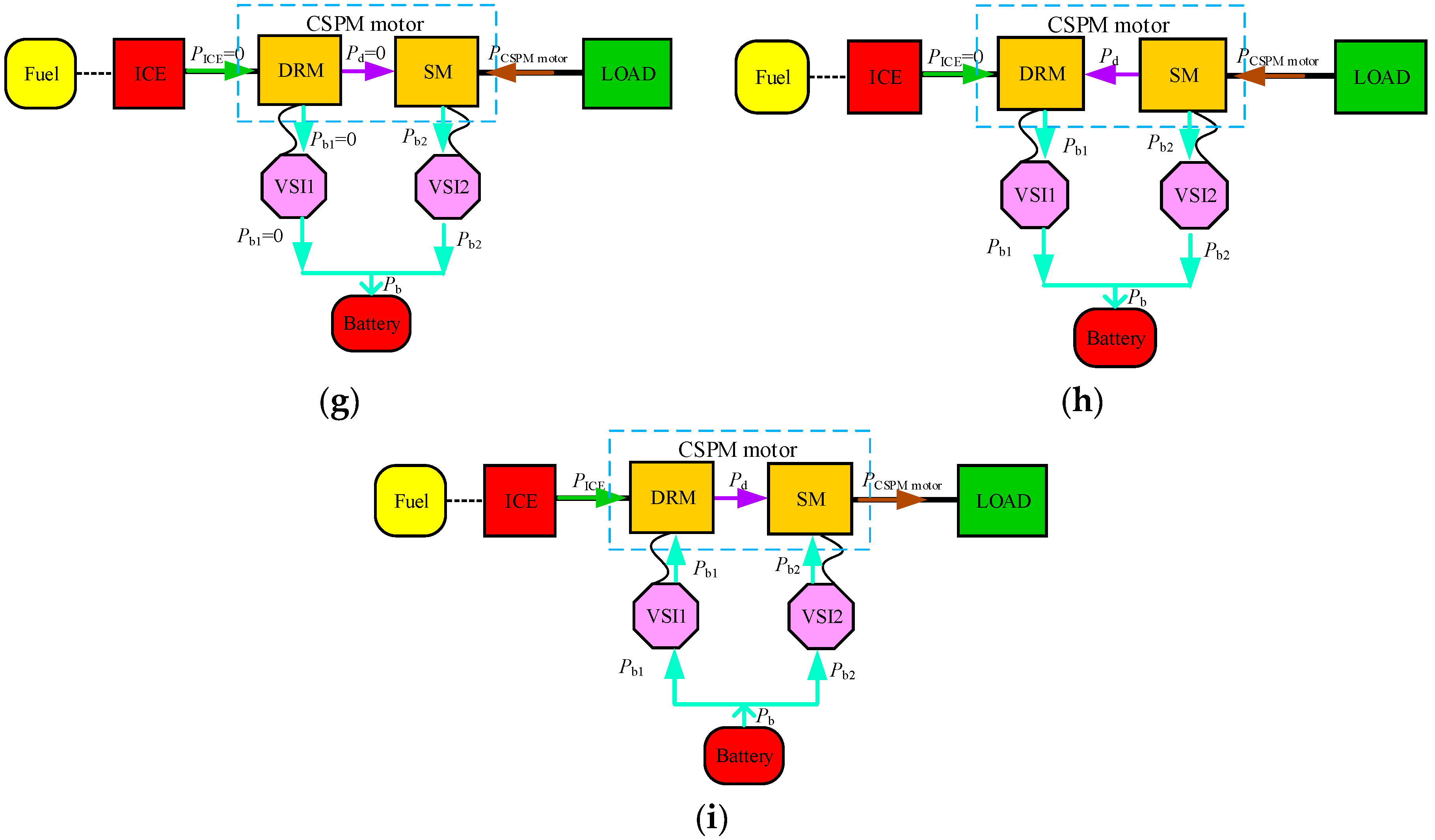
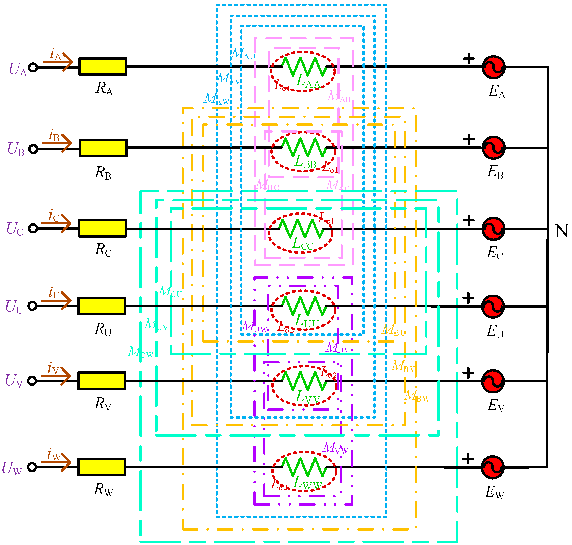
To study the state equation of CSPM motor in three-phase stationary coordinate system, the equivalent circuit diagram of CSPM motor is shown in Figure 3. Here, UA, UB, UC, UU, UV, UW is the voltage of three-phase stator winding and inner rotor winding; iA, iB, iC, iU, iV, iW is the current of three-phase stator winding and inner rotor winding, and RA, RB, RC, RU, RV, RW is the resistance of them; LXX is the self-inductance of each phase winding; MXY is the mutual inductance between different phase windings; and EA, EB, EC, EU, EV, EW is the back EMF produced by the outside and the inside permanent magnet cutting the stator and inner rotor windings.
From Figure 3, it can be seen that the magnetic circuit parameters of CSPM motor contain resistance, self-inductance, and mutual inductance, which are related to the position and speed of inner rotor and outer rotor, etc. Therefore, the CSPM motor is a nonlinear system with multiple variables, strong coupling, and uncertain parameters. For simplicity, the variables of CSPM motor need to be simplified as follows:
(1) Neglecting magnetic circuit saturation; (2) neglecting eddy current loss and hysteresis effect; (3) The resistance of three phase winding is equal; (4) The back EMF and flux linkage of the stator winding and inner rotor winding, and the flux linkage of permanent magnet, are the sinusoidal waveforms; (5) The distribution of inner and outer air-gap is uniform, and the reluctances of them are constant.
Then, the relationship between the voltage (U) and the resistance (R), the current (I), and the flux linkage (Ψ) of CSPM motor in the three-phase stationary coordinate system is expressed in Equation (1).
in which ΨA, ΨB, ΨC, ΨU, ΨV, ΨW is the flux linkage of three-phase stator winding and inner rotor winding, which is related to the outer rotor’s position (θ1), inner rotor’s position (θ2), current, and the flux linkage of permanent magnet, as shown in Equation (2).
in which Ψm1 is the flux linkage produced by the outside permanent magnet and Ψm2 is the flux linkage produced by the inside permanent magnet. The relationship between LXX and MXY can be written as
In Equation (3), Lσ1 and Lσ2 is the leakage inductance of outer rotor and inner rotor, respectively; Lσ is the difference between Lσ1 and Lσ2; LV is the average inductance; and L(θ1), L(θ2), L(θ2 − θ1) is the position inductance that is influenced by the position of outer rotor and inner rotor.
Substituting Equation (2) for Equation (1), the new voltage expression of CSPM motor is in Equation (4). The resistance matrix (R), mutual inductance matrix (Lm), and the derivative of Lm (Lm’) are shown in Equation (5).
in which ω1, ω2 is the electric angular velocity of the outer rotor and inner rotor, and iX’ is the derivative of iX.
The electromagnetic torque is the partial derivative of magnetic co-energy to the rotor mechanical angle; then, the torque representation of outer rotor (Tor) and inner rotor (Tir) can be obtained in Equation (6) based on the virtual displacement method. Here, Pn is the pole-pair number of CSPM motor, T1 and T3 is the electromagnetic torque produced by stator on the outer rotor and inner rotor, respectively. The electromagnetic torque generated by the outer rotor on the outer rotor or produced by the outer rotor on the inner rotor is identical, which is expressed by T2.
in which
From Equation (6), it can be seen that the torque of outer rotor is related to the current, inductance, and mutual inductance in stator winding and inner rotor winding, flux linkage of permanent magnet, while the torque of inner rotor is involved in the inner rotor current, mutual inductance between the two sets of windings, mutual inductance between stator winding, and inner rotor winding, flux linkage of permanent magnet. The inductance and mutual inductance in stator winding and inner rotor winding are changed with two rotor’s position, and will also be changed when the magnetic field is saturated, which causes the torque ripples of the two rotors [14,15]. The current of stator winding and inner rotor winding can also affect the torque ripple. This is because the three-phase current in the two sets windings will produce a rotating magnetic field with three speeds in the outer and inner air-gap, since the magnetic circuit of outer rotor is asymmetrical. If the frequency of stator current is fs, it will generate a magnetic field with the speeds n1, (1 − s1) n1, and (1 − 2s1) n1; s1 is the transfer rate in SM, while in DRM, the frequency of inner rotor current is fir, which also produces three magnetic fields in the inner air-gap, i.e., n2, (1 − s2) n2, and (1 − 2s2) n2; s2 is the transfer rate in DRM. The magnetic field with different speed interactions with each other will result in the torque ripple. These aspects are analyzed in the next part to add the output torque and decrease the torque ripple of CSPM motor.
When CSPM motor operates in the load condition, the flux linkage produced by the stator winding and inner rotor winding current interacts with the flux linkage of inner and outer permanent magnets, then generates the electromagnetic torque on the outer rotor. The electromagnetic torque and load demand torque interact with each other to keep the outer rotor running smoothly. Therefore, the matching between the two currents and permanent magnet size will also affect the output torque performance.
4. Analysis and Optimization of CSPM Motor Based on FEM
This section studies the torque properties of CSPM motor by optimizing the design of the electromagnetic parameters. The total output torque of CSPM motor is the sum of output torque of SM and DRM, so their torque properties are studied separately.
The analyzed variables used to investigate the torque capabilities are as follows:
- (1)
- The variation range of air-gap length is between 0.35 mm and 0.75 mm, and the variable step is 0.05 mm;
- (2)
- The variation range of core length is 85 mm to 120 mm, and the variation step is 5 mm;
- (3)
- The current frequency of two sets winding changes from 112 Hz to 161 Hz, and the variable step is 5 Hz. The current of stator winding and inner rotor winding is between 150 A and 180 A, and the change step is 10 A.
- (4)
- The variation of the polar arc coefficient for permanent magnet is 0.5–0.9, and the step length is 0.05. The current change rule of stator winding and inner rotor winding is as (3);
- (5)
- The thickness of permanent magnet varies in the range of 3.5–5.5 mm, and the step length is 0.25 mm. The current also changes as (3);
- (6)
- The skewing-slot angle changes from 1 degree to 15 degrees, and the variable step is 1 degree.
- (7)
- The percentage of torque ripple (Tripple) is defined as follows:
The detailed analysis process and results are displayed as follows.
4.1. Air-Gap Length
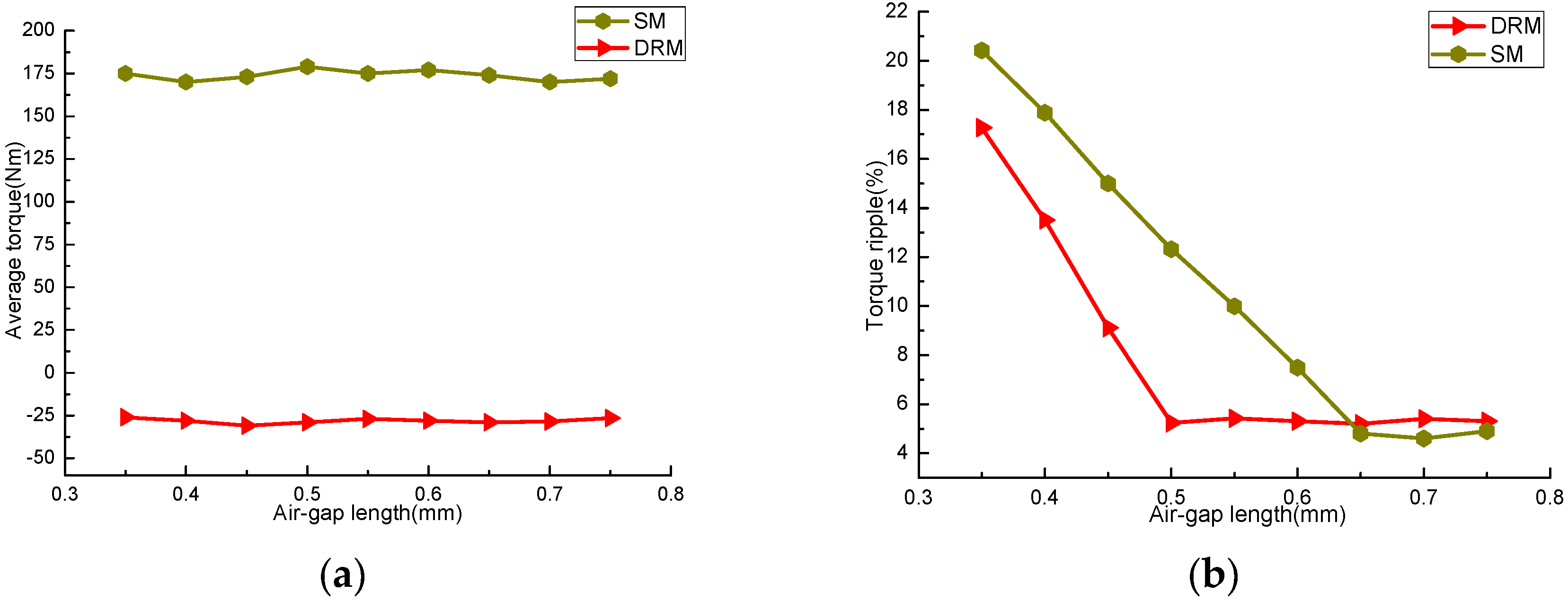
The air-gap length influences the air-gap harmonic content, and also affects the performance, reliability, processing difficulty, and cost of CSPM motor [16]. Figure 4 shows the curves of average torque and torque ripple percentage of SM and DRM. The curve of DRM corresponds to the length of inner air-gap, and that of SM relates to the length of outer air-gap.
In Figure 4a, it can be seen that with the increasing of air-gap length, the average torques of DRM and SM are basically stable. The average torque of DRM is about −26 Nm, and that of SM is around 175 Nm. Positive and negative sign represents the fact that the SM and DRM are working in different states, i.e., electric state or power generation state, while in Figure 4b, the torque ripple degree of the two machines decreases seriously with the increase of air-gap length, then tends to be stable. The torque ripple of DRM decreases obviously with the increase of air gap length when the inner air-gap length is 0.35 mm–0.5 mm. When the length exceeds 0.5 mm, the fluctuation range is small. The reason is that the smaller air-gap length reduces the installation coaxial degree of CSPM motor, increasing the vibration and noise during operation. For SM, the torque ripple decreases rapidly when the range of outer air-gap length is 0.35 mm–0.65 mm, then changes steadily. Therefore, the torque ripple can be significantly reduced via optimizing the air-gap length, and has small impact on the output torque.
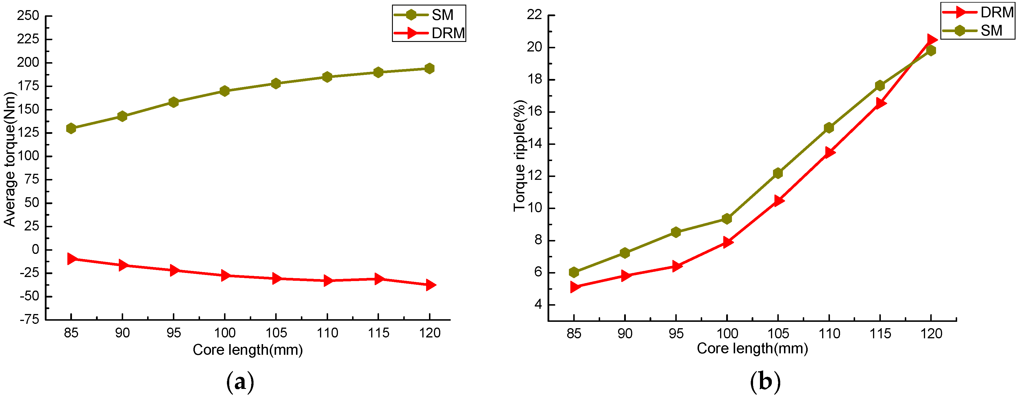
4.2. Core Length
The core length of CSPM motor affects its electromagnetic load. The average torque and torque ripple percentages of SM and DRM with different core lengths are shown in Figure 5.
Figure 5 shows that, the longer the core is, the larger the average torque is, and the greater the torque ripple is. This is because the raise of core length increases the magnetic flux variation in the two windings, which adds the magnetic co-energy and then increases the average torque of the two machines. The longer core length will also increase the edge flux, which raises the radial magnetic force and the torque ripple. In actual design, the core can be lengthened properly to increase the output torque of CSPM motor. Nevertheless, this method also increases the torque ripple seriously, and the material amount and processing cost will also increase.
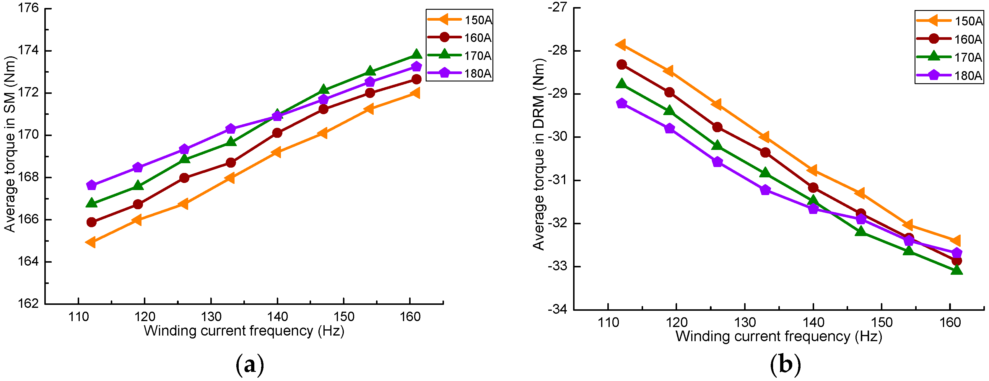
4.3. Different Winding Current Frequency
Figure 6a shows the average torque of SM at different stator winding current frequencies, and Figure 6b shows DRM at different inner rotor winding current frequencies. One can find that the average torque of the two machines increases with the increasing of current frequency when the current remains constant. This is because the increasing of current frequency reduces the magnetic flux, which decreases the magnetic coupling degree in SM and DRM. Also, it can be found that, under the same current frequency, the average torque of them increases with the current. However, when the current increases to a certain degree, the torque has a declining trend. In Figure 6a, it can be seen that the average torque of SM when the stator current is 180 A is smaller than the value with the current is 170 A, after the current frequency is more than 140 Hz, while Figure 6b also features a similar situation. This is because the larger current has increased the magnetic field’s saturation degree. When the magnetic field is oversaturated, the magnetic flux lines flowing in the SM and DRM interfere with each other, which weakens the intensity of the air-gap magnetic field, reducing the torque output capacity.
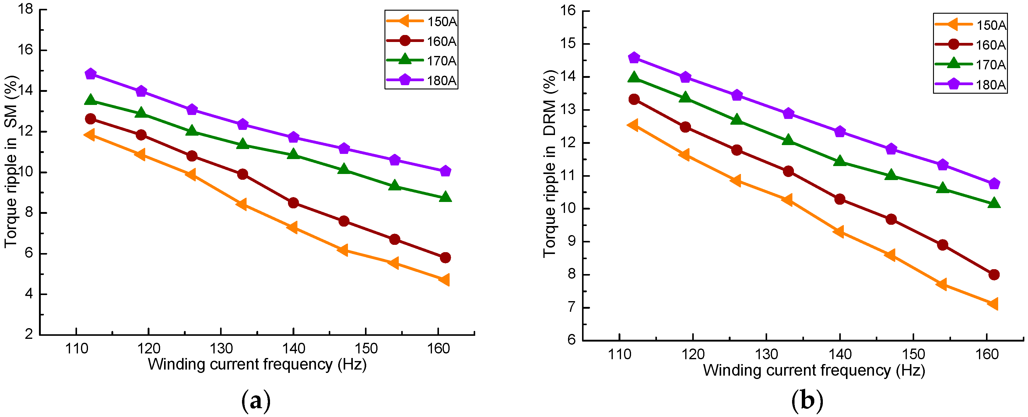
The torque ripple produced by SM and DRM at different currents and current frequencies is given in Figure 7. It can be known that the torque ripple reductions are correlated with the current frequency adds under the same current. When the current in the two sets of winding is 170 A and 180 A, respectively, the torque declines slower than the currents 150 A and 160 A. This is because the adding of the current causes the magnetic field to reach a saturation state more easily; then, the magnetic circuit parameters will be changed, which impacts the working stability.
4.4. Matching between Permanent Magnet Size and Winding Currents
In order to reduce the magnetic field coupling degree between SM and DRM, as well as the size of CSPM motor, the magnetization direction of permanent magnets on both sides of the outer rotor is in the radial direction. The structural dimensions of permanent magnet include axial length, circumferential width, and magnetizing direction thickness. The axial length of permanent magnet is usually the same as the length of the core. This section improves the performance of CSPM motor by optimizing the matching relationship between the two winding currents and the width, the thickness of the permanent magnets.
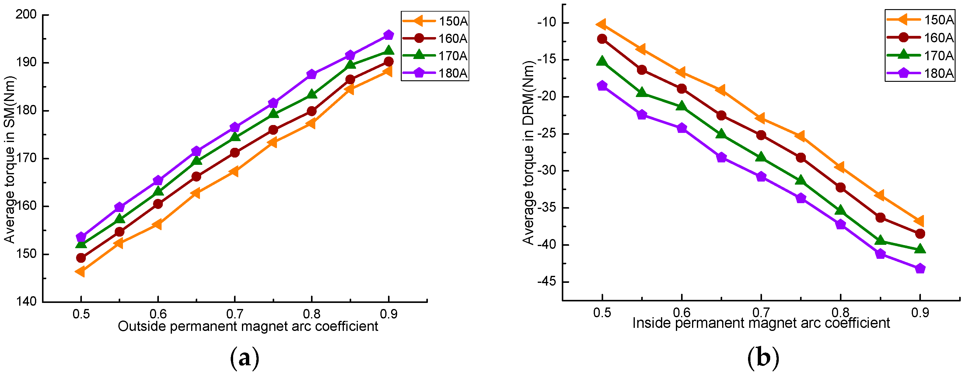
The pole arc coefficient of the permanent magnet is the ratio of the width to pole distance, which affects the magnetic flux per pole, air-gap flux density, the corresponding position between stator slot and outer permanent magnets, and the corresponding position between inner rotor slot and inner permanent magnets. The influence of permanent magnet’s width on the torque characteristics can be studied by changing the pole arc coefficient of it. Figure 8 is the effect of permanent magnet pole arc coefficient on the average torque. Figure 8a shows the stator winding current, and Figure 8b shows the inner rotor winding current.
As can be seen in Figure 8, the average torque of SM and DRM continually increased with the rise of permanent magnet pole arc coefficient. The main cause is that the increase of pole arc coefficient adds the magnetic flux produced by the permanent magnet, so the total magnetic flux flowing in the SM and DRM also increases. Although the number of stator and inner rotor winding turns is constant, the flux linkage in the two machines also increases, which results in the output torque increasing. The average torque of the two machines also increases with the larger current under the same polar arc coefficient.
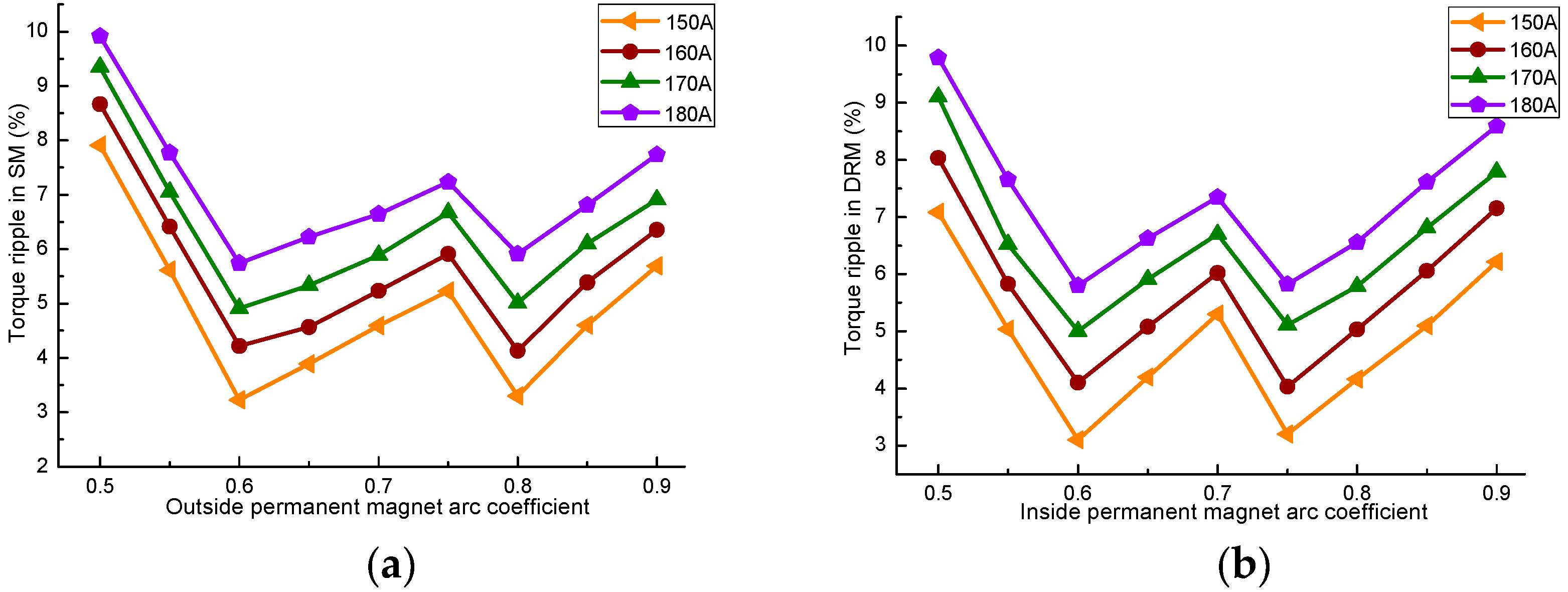
The relationship between the torque ripple and the polar arc coefficient is shown in Figure 9. It can be observed that the pole arc coefficient of permanent magnet has great influence on the torque ripple. With the increase of pole arc coefficient, the torque ripple of SM and DRM decreases first, then increases, decreases, and, lastly, increases. The torque ripple of SM obtains the minimum when the polar arc coefficient is 0.6 and 0.8, while the DRM obtains the minimum at 0.6 and 0.75. Under the same polar arc coefficient, the torque ripple of SM will increase with the addition of the stator winding current, and that of the DRM will also increase with the increase of the inner rotor winding current.
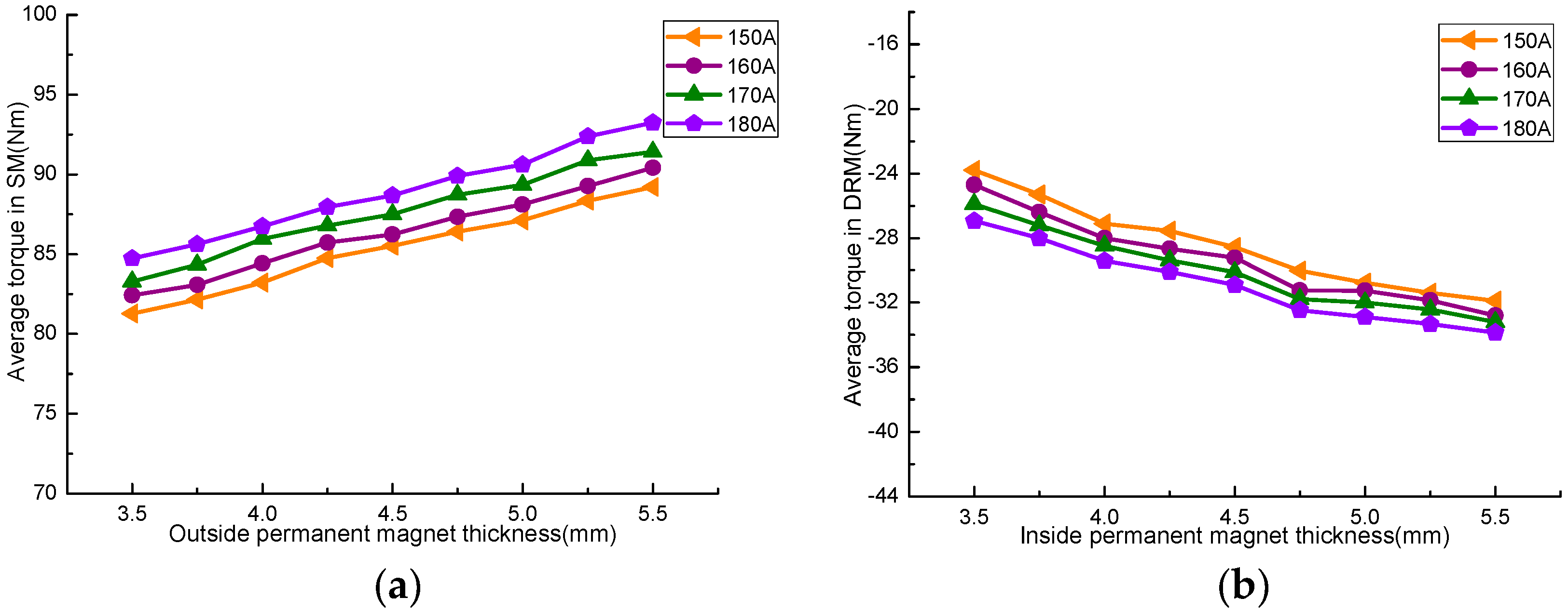
The thickness of the two layers permanent magnet is related to the electrical load, efficiency, and the back EMF waveform of CSPM motor. Figure 10 gives the average torque of SM and DRM with different thicknesses of permanent magnets.
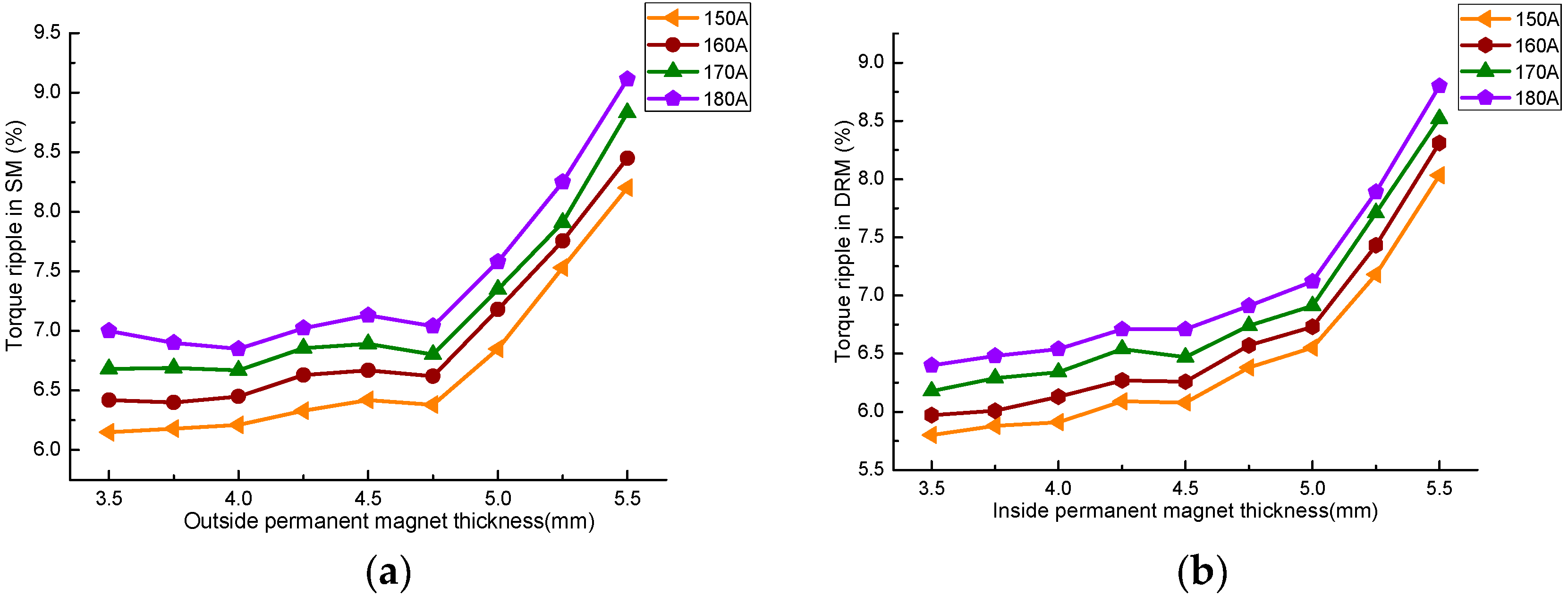
As seen in Figure 10, the average torque also increases with the larger permanent magnet’s thickness. However, the effect of permanent magnet’s thickness on the torque value is smaller than that of the width. The increase of the two current excitations also increases the output torque. Figure 11 is the relationship of torque ripple between SM, DRM, and permanent magnet thickness.
From Figure 11, it can be seen that with the increase of the permanent magnet’s thickness, the torque ripple of SM and DRM shows the similar tendency. The increase of the current will increase the torque ripple under the same permanent magnet thickness. The torque ripple increases with the thickness under the same current. This is because the raise of flux produced by the two excitation sources makes the magnetic circuit easy to saturate, then aggravates the output torque fluctuation. When the thickness of SM and DRM is less than 5 mm and 4.75 mm, the torque ripple raises slowly and then increases significantly. The output torque of CSPM motor can be increased by increasing the thickness of permanent magnet properly, but the stability of the torque output will become worse if the thickness is too large.
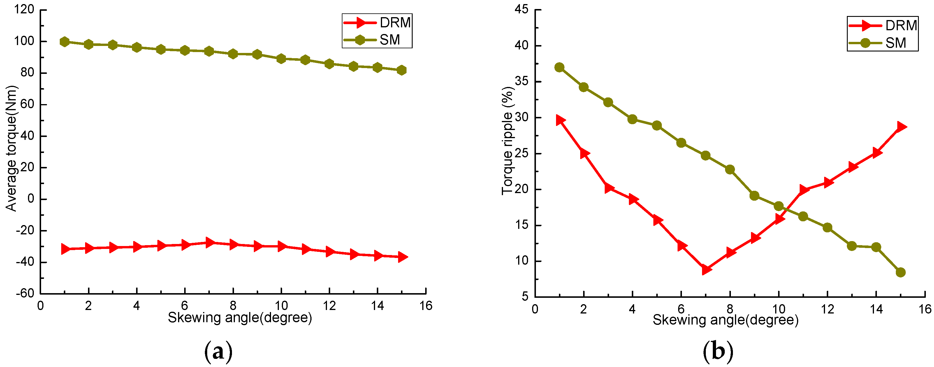
4.5. Skewed Slots
The skewing-slot of stator and inner rotor core can weaken the tooth harmonic potential, optimize the back EMF waveform, and output torque waveform [17,18]. The average torque and torque ripple percentages of SM and DRM with different skewing angles are shown in Figure 12. The skewing angle of stator affects the torque properties of SM, and the skewing angle of inner rotor affects the torque properties of DRM.
From Figure 12a, it can be seen that the increasing of skewed slot will slightly weaken the output torque. The torque average in SM drops from 100 Nm to 80 Nm within the range of skewing angle. The changing trend of torque in DRM is slightly reduced and then increased, and 7 degrees is the turning point. However, the skewed slot has a good effect on reducing the torque ripple. Figure 12b shows that the torque ripple of SM and DRM decreases observably with the increasing skewing angle in stator and inner rotor, but the specific changes are different. The torque ripple percentage of SM continuous declines from 37.3% to 8.6% and achieves the minimum when the skewing angles are 15 degrees. The change curve of torque ripple in DRM is “V” type, and reaches its lowest point when the skewing angles is 7 degrees. The reason is that when the skewing angles of stator and inner rotor are 15 degrees and 7 degrees, respectively, the first order tooth harmonic magnetic field in the two machines can be effectively weakened; then, the air-gap harmonic magnetic field also be decreased. The skewed slot of the stator and inner rotor changes the conductor distribution in the magnetic field. It causes the induced voltage and radial force of every conductor to have a spatial phase difference along the axial direction. Thus, the effective part of the magnetic field will be reduced; then, the coupling action in the SM and DRM will be weakened.
5. Performance Comparison before and after Optimization
According to the above electromagnetic parameters optimization design, the design parameters of CSPM motor are given in Table 1.
The FEM model of CSPM motor is established based on the selected parameters, as shown in Figure 13.
In order to reduce the FEM calculation time, the 1/8 FEM model of CSPM motor is adopted for analyses due to its symmetrical structure [19,20]. The electromagnetic performances of CSPM motor before and after optimization are compared using the 1/8 FEM model based on FEM, and the simulation results, which include the field distribution, induced voltage, flux linkage, and output torque, are given as follows.
5.1. Field Distribution
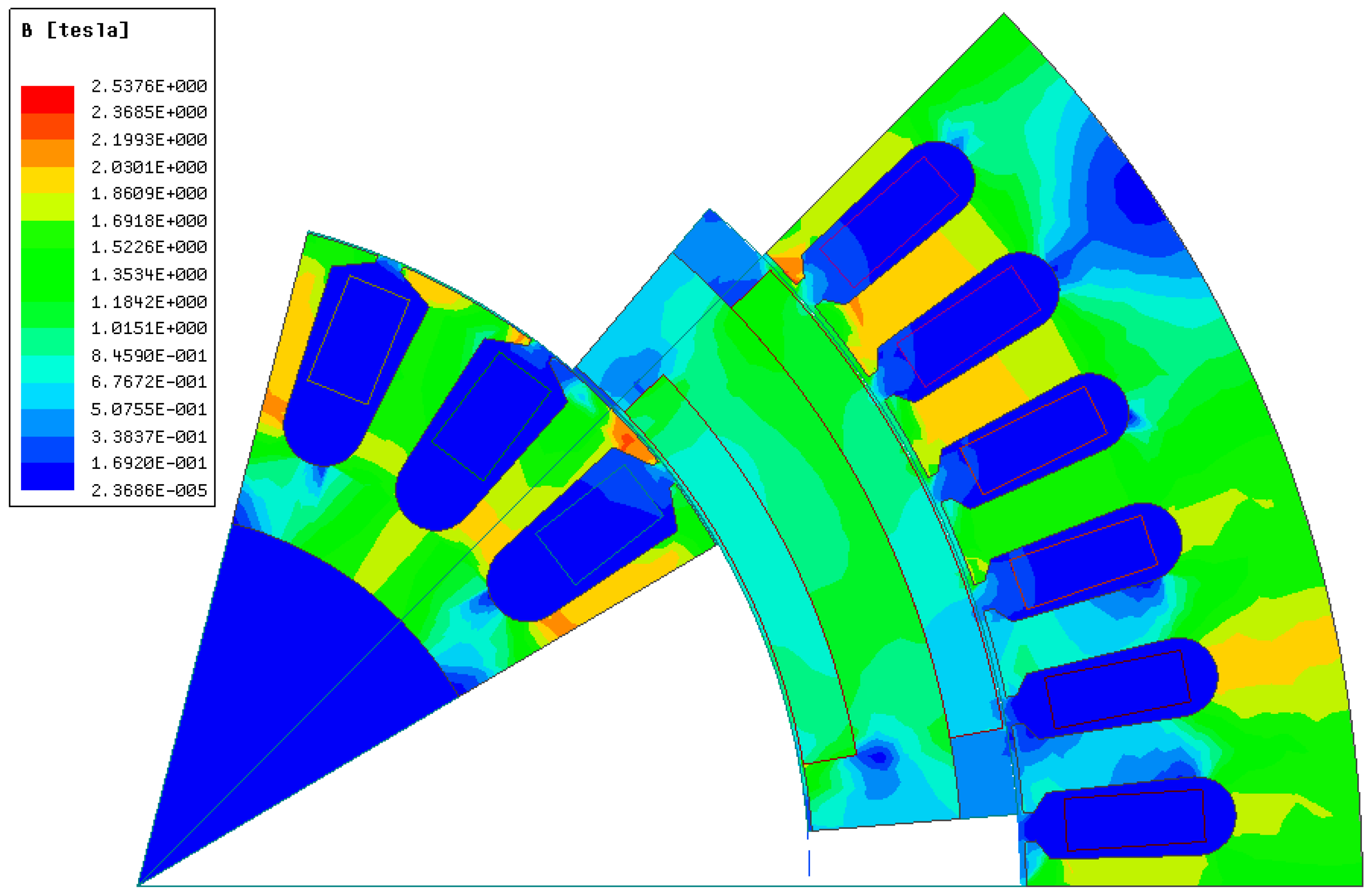
The magnetic flux density distribution of CSPM motor at rated load is shown in Figure 14.
As can be seen from Figure 14, the larger magnetic flux density appears in the stator tooth, part of the stator yoke, and the inner rotor tooth, which is about 2 T. The magnetic flux density in most part of the stator yoke, inner rotor yoke, and outer rotor yoke is about 1.69 T, while the lowest magnetic flux density arises in the stator slot and inner rotor slot, which can not only increase the power density of CSPM motor, but also greatly reduce the iron consumption at high speed. The heat dissipation of inner rotor is more difficult, for it is located in the innermost part of CSPM motor. The lower magnetic flux density will also improve the heat dissipation performance of DRM, thus improving the insulation reliability. At this time, the unsaturated magnetic field reduces the mutual coupling between SM and DRM, which strengthens the working stability and control accuracy of this transmission.
5.2. Induced Voltage before and after Optimization
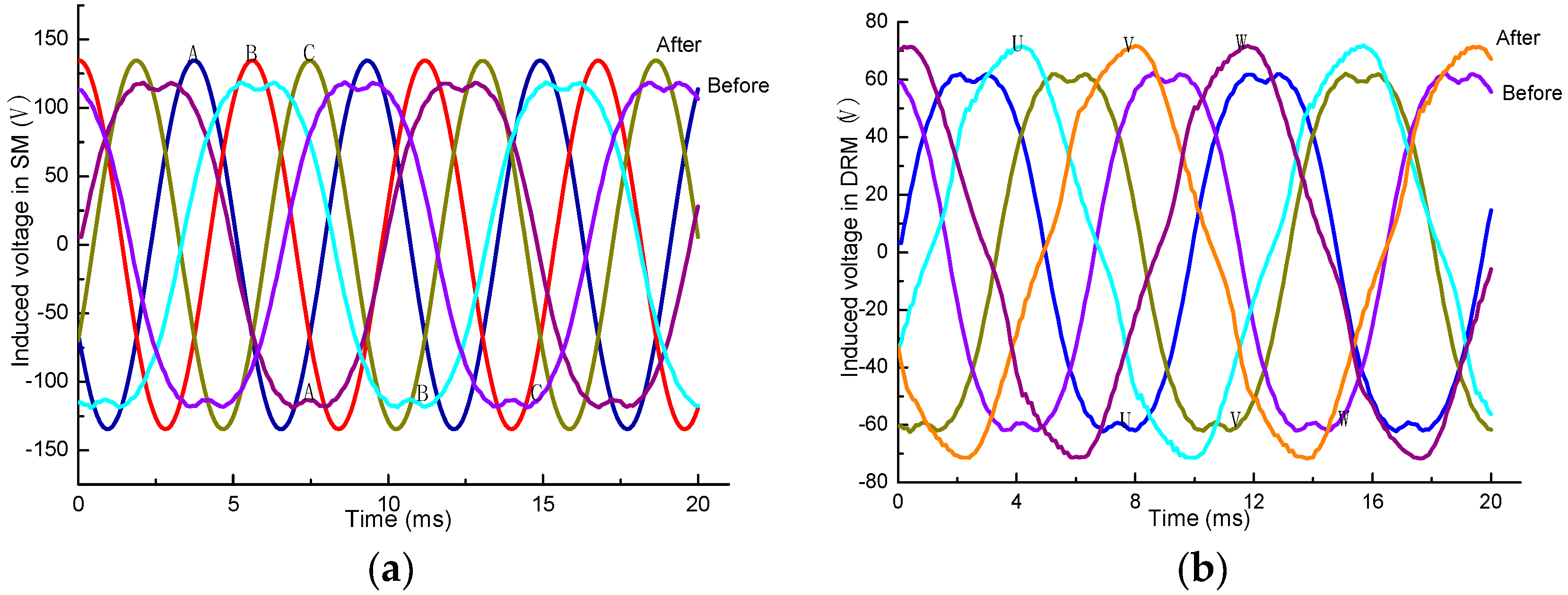
The back EMF waveforms in the stator and inner rotor windings before and after the optimization are compared in Figure 15.
It can be seen from Figure 15 that before the optimization design of electromagnetic parameters, the back EMF waveforms in the three phase windings (ABC) and inner rotor three phase winding (UVW) are flat-topped, which are seriously distortion. After the above parameter optimization, the back EMF waveform of the stator windings and inner rotor windings had a better sine character. The back EMF with good sinusoidal degree can improve the control accuracy of the whole vehicle system and reduce the loss and torque ripple. The amplitudes of the two windings also increase compared with the former. The peak-peak value of back EMF in the stator windings before optimization is about 242.5 V, which then changes into 270.8 V after optimization. In the inner rotor winding, the former peak-peak value of back EMF is approximately 121.3 V, which then increases to 142.7 V. The results show that the harmonics in the inner and outer air-gap is dominated by the fundamental content after optimization. The better magnetic characteristics of air-gap can increase the linearity of magnetic circuit parameters and reduce the interference between SM and DRM; then, the output torque smoothness of CSPM motor is also improved.
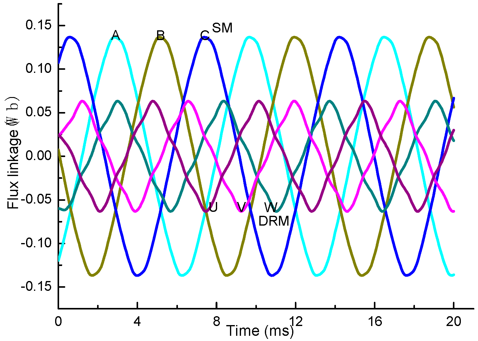
Figure 16 is the flux linkage waveform of the stator and inner rotor windings after optimization. It can be seen that the flux linkage waveforms of the two sets of windings are close to the sine wave, and the sinusoidal degree of the stator windings is a little higher. Therefore, the best way to optimize the flux linkage waveform and improve the magnetic field distribution of DRM should continue to be investigated, to make the energy transmission in the CSPM motor more flexible to enhance the working performance of it.
5.3. Output Torque before and after Optimization
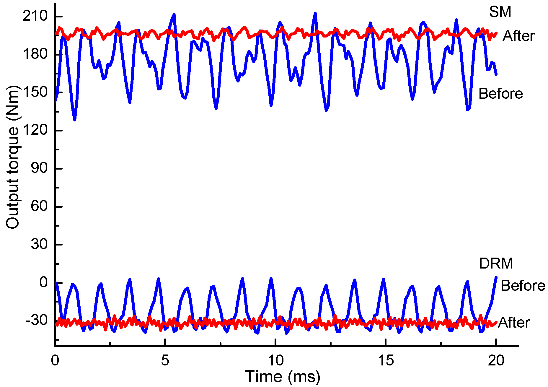
The output torque waves of SM and DRM are shown in Figure 17. The blue curve represents the output torque before optimization, while the red curve represents the output torque after optimization. It can be seen that the torque ripple of CSPM motor decreases significantly after parameters optimization, and the output torque is increased compared with the former. Before optimization, the average output torque for SM and DRM was 168.4 Nm and −19.6 Nm, respectively.
The torque ripples of SM and DRM are 14.7% and 55.3%, respectively, while after optimization, the average output torque for SM is about 196.2 Nm with a torque ripple of 2.5%, and that of the DRM is about −31.8 Nm with a torque ripple of 3%. The result from FEM shows good output torque of CSPM motor. Smooth output torque can improve the control accuracy and the reliability of the system, which are better suited to be used in HEVs.
6. Conclusions
As an electromechanical energy conversion device in the hybrid power system, the CSPM motor can realize the different energy flows in HEVs and then transfer the torque to drive the vehicle. The energy transmission depends on the electromagnetic field coupling effect between the two machines, i.e., SM and DRM. The electromagnetic parameters of CSPM motor will become nonlinear when the magnetic field becomes supersaturated, which will affect the work performance of the machine. This paper is designed to raise the output torque and reduce the torque ripple of CSPM motor used for HEVs. The system configuration, working mode, and state equation of CSPM motor are described, separately. The electromagnetic parameters are analyzed and optimized, and appropriate design parameters are received. Then, the performances of CSPM motor before and after optimization are contrasted to demonstrate better working stability. The crux findings of the electromagnetic parameters selection for CSPM motor during the investigation are distilled as follows.
- (1)
- By increasing the air-gap length properly, the torque ripple will be reduced, and there is little impact on the output torque value;
- (2)
- The longer core should be chosen to add the average torque of the CSPM motor. However, this method also increases the torque ripple;
- (3)
- The average torque increases with the increase of current frequency under the same current; it also increases with the current under the same current frequency. However, the torque will decrease when the current increases to a certain degree. The torque ripple decreases with the increase of current frequency;
- (4)
- Choosing a larger pole arc coefficient and thickness of permanent magnet will add the average torque. The pole arc coefficient has a great influence on the torque ripple, and the increasing speed of torque ripple gradually increases with the thickness when the current unchanged.
- (5)
- The increase of skewing angle decreases the torque ripple of the CSPM motor observably, and the output torque decreases a little.
Author Contributions
Conceptualization, J.H.; Data curation, D.T.; Formal analysis, J.S. and S.C.; Funding acquisition, Q.X.; Investigation, W.W.; Methodology, W.W.; Project administration, Q.X.; Resources, Q.X.; Software, D.T.; Validation, J.H. and S.C.; Visualization, S.C.; Writing-original draft, J.S.; Writing-review & editing, J.S.
Funding
This work was supported by National Natural Science Foundation of China under Project No. 51507021, Chongqing Science and Technology Commission of China under Project No. cstc2013jcyjA60001, graduate research and innovation foundation of Chongqing, China under Project No. CYS17008 and The State Key Laboratory of Power Transmission Equipment & System Security and New Technology in Chongqing University of China under Project No. 2007DA10512716303.
Conflicts of Interest
The authors declare no conflict of interest.
References
- Xu, Q.W.; Sun, J.; Su, Y.M.; Chen, W.D.; Huang, J.S.; Cui, S.M. Study on the magnetic coupling and decoupling algorithm of electrical variable transmission. In ICSEE 2017, LSMS 2017: Intelligent Computing, Networked Control, and Their Engineering Applications; Springer: Singapore, 2017; Volume 762, pp. 146–155. [Google Scholar]
- Zhang, G.; Hua, W.; Cheng, M.; Liao, J. Design and comparison of two six-phase hybrid-excited flux-switching machines for EV/HEV applications. IEEE Trans. Ind. Electron. 2016, 63, 481–493. [Google Scholar] [CrossRef]
- Xu, Q.W.; Sun, J.; Li, L.Y.; Shi, Y.L. Magnetic decoupling scheme selection of electric variable transmission used for hybrid electric vehicle. In Proceedings of the 2017 IEEE Transportation Electrification Conference and Expo, Asia-Pacific (ITEC Asia-Pacific), Harbin, China, 7–10 August 2017; pp. 1–6. [Google Scholar]
- Bai, J.G.; Zheng, P.; Tong, C.D.; Song, Z.Y.; Zhao, Q.B. Characteristic analysis and verification of the magnetic-field modulated brushless double-rotor machine. IEEE Trans. Ind. Electron. 2015, 62, 4023–4033. [Google Scholar] [CrossRef]
- Liu, Y.L.; Ho, S.L.; Fu, W.N. Novel electrical continuously variable transmission system and its numerical model. IEEE Trans. Magn. 2014, 50, 7018704. [Google Scholar] [CrossRef]
- Xu, Q.W.; Sun, J.; Luo, L.Y.; Cui, S.M.; Zhang, Q.F. A Study on Magnetic Decoupling of Compound-Structure Permanent-Magnet Motor for HEVs Application. Energies 2016, 9, 819. [Google Scholar] [CrossRef]
- Laskaris, K.I.; Kladas, A.G. Internal permanent magnet motor design for electric vehicle drive. IEEE Trans. Ind. Electron. 2010, 57, 138–145. [Google Scholar] [CrossRef]
- Wang, A.; Jia, Y.; Soong, W.L. Comparison of Five Topologies for an Interior Permanent-Magnet Machine for a Hybrid Electric Vehicle. IEEE Trans. Magn. 2011, 47, 3606–3609. [Google Scholar] [CrossRef]
- Cao, R.; Mi, C.; Cheng, M. Quantitative comparison of flux-switching permanent-magnet motors with interior permanent magnet motor for EV, HEV and PHEV applications. IEEE Trans. Magn. 2012, 48, 2374–2384. [Google Scholar] [CrossRef]
- Maloberti, O.; Figueredo, R.; Marchand, C.; Choua, Y.; Condamin, D.; Kobylanski, L.; Bommé, E. 3-D–2-D dynamic magnetic modeling of an axial flux permanent magnet motor with soft magnetic composites for hybrid electric vehicles. IEEE Trans. Magn. 2014, 50, 8201511. [Google Scholar]
- Ni, R.; Wang, G.; Gui, X.G.; Xu, D.G. Investigation of d- and q-axis inductances influenced by slot-pole combinations based on axial flux permanent-magnet machines. IEEE Trans. Ind. Electron. 2014, 61, 4539–4551. [Google Scholar] [CrossRef]
- Pellerey, P.; Lanfranchi, V.; Friedrich, G. Coupled numerical simulation between electromagnetic and structural models. Influence of the supply harmonics for synchronous machine vibrations. IEEE Trans. Magn. 2012, 48, 983–986. [Google Scholar] [CrossRef]
- Lei, G.; Zhu, J.G.; Guo, Y.G.; Liu, C.C.; Ma, B. A review of design optimization methods for electrical machines. Energies 2017, 10, 1962. [Google Scholar] [CrossRef]
- Seo, J.H.; Choi, H.S. Cogging torque calculation for IPM having single layer based on magnetic circuit model. IEEE Trans. Magn. 2014, 50, 8102104. [Google Scholar] [CrossRef]
- Zou, J.B.; Zhao, B.; Xu, Y.X.; Zhao, M. The torque ripple and minimization in multi-unit permanent magnet synchronous motor for electromagnetic thruster. In Proceedings of the 2012 16th International Symposium on Electromagnetic Launch Technology, Beijing, China, 15–19 May 2012; pp. 1–6. [Google Scholar]
- Shen, Q.P.; Xu, Q.W. Design of variable air gap axial flux permanent magnet machine for extending the speed region. In Proceedings of the 17th International Conference on Electrical Machines and Systems (ICEMS), Hangzhou, China, 22–25 October 2014; pp. 1114–1118. [Google Scholar]
- Gan, C.; Wu, J.H.; Shen, M.J.; Yang, S.Y.; Hu, Y.H.; Cao, W.P. Investigation of skewing effects on the vibration reduction of three-phase switched reluctance motors. IEEE Trans. Magn. 2015, 51, 8203509. [Google Scholar] [CrossRef]
- Islam, R.; Husain, I.; Fardoun, A.; McLaughlin, K. Permanent-magnet synchronous motor magnet designs with skewing for torque ripple and cogging torque reduction. IEEE Trans. Ind. Appl. 2009, 45, 152–160. [Google Scholar] [CrossRef]
- Lei, G.; Wang, T.S.; Zhu, J.G.; Guo, Y.G.; Wang, S.H. System-level design optimization method for electrical drive systems-robust approach. IEEE Trans. Ind. Electron. 2015, 62, 4702–4713. [Google Scholar] [CrossRef]
- Lei, G.; Wang, T.S.; Guo, Y.G. System-level design optimization methods for electrical drive systems: Deterministic approach. IEEE Trans. Ind. Electron. 2014, 61, 6591–6602. [Google Scholar] [CrossRef]
Figure 1.
Diagram of hybrid electric vehicles (HEVs) based on compound-structure permanent-magnet motor (CSPM motor).
Figure 1.
Diagram of hybrid electric vehicles (HEVs) based on compound-structure permanent-magnet motor (CSPM motor).

Figure 2.
Power flow process of HEVs based on CSPM motor in different working mode: (a) pure electric mode; (b) CVT mode; (c) auxiliary power mode; (d) driving and parking generation mode; (e) driving and parking generation mode; (f) electric braking mode; (g–h) regenerative braking mode; (i) over-speed mode.


Figure 3.
Equivalent circuit diagram of CSPM motor.

Figure 4.
Average torque and torque ripple curve of stator machine (SM) and double-rotor machine (DRM) with different air-gap length: (a) Average torque; (b) Torque ripple.
Figure 4.
Average torque and torque ripple curve of stator machine (SM) and double-rotor machine (DRM) with different air-gap length: (a) Average torque; (b) Torque ripple.

Figure 5.
Average torque and torque ripple curves of SM and DRM with different core lengths: (a) SM; (b) DRM.
Figure 5.
Average torque and torque ripple curves of SM and DRM with different core lengths: (a) SM; (b) DRM.

Figure 6.
Variation of average torque curve in SM and DRM with winding current frequency: (a) SM; (b) DRM.
Figure 6.
Variation of average torque curve in SM and DRM with winding current frequency: (a) SM; (b) DRM.

Figure 7.
Variation of torque ripple in SM and DRM with winding current frequency: (a) SM; (b) DRM.

Figure 8.
Variation of average torque in SM and DRM with permanent magnet pole arc coefficient: (a) SM; (b) DRM.
Figure 8.
Variation of average torque in SM and DRM with permanent magnet pole arc coefficient: (a) SM; (b) DRM.

Figure 9.
Variation of torque ripple in SM and DRM with permanent magnet pole arc coefficient: (a) SM; (b) DRM.
Figure 9.
Variation of torque ripple in SM and DRM with permanent magnet pole arc coefficient: (a) SM; (b) DRM.

Figure 10.
Relationship of average torque between SM, DRM, and permanent magnet thickness: (a) SM; (b) DRM.
Figure 10.
Relationship of average torque between SM, DRM, and permanent magnet thickness: (a) SM; (b) DRM.

Figure 11.
Relationship of torque ripple between SM, DRM, and permanent magnet thickness: (a) SM; (b) DRM.
Figure 11.
Relationship of torque ripple between SM, DRM, and permanent magnet thickness: (a) SM; (b) DRM.

Figure 12.
Average torque and torque ripple curve of DRM and SM with different skewing angles: (a) Average torque; (b) Torque ripple.
Figure 12.
Average torque and torque ripple curve of DRM and SM with different skewing angles: (a) Average torque; (b) Torque ripple.

Figure 13.
FEM model of CSPM Motor.

Figure 14.
Magnetic density distribution of CSPM motor at rated load.

Figure 15.
Induced voltage of stator windings and inner rotor windings: (a) Stator windings; (b) Inner rotor windings.
Figure 15.
Induced voltage of stator windings and inner rotor windings: (a) Stator windings; (b) Inner rotor windings.

Figure 16.
Flux linkage of stator and inner rotor windings.

Figure 17.
Output torque comparison of SM and DRM before and after optimization.


Table 1.
Design parameters of CSPM motor.
| Design Parameters | DRM | SM | ||
|---|---|---|---|---|
| Rated power (kW) | 15 | 30 | ||
| Rated speed (rpm) | 5000 | 2200 | ||
| Number of phase | 3 | 3 | ||
| Number of slot | 24 | 48 | ||
| Air-gap length (mm) | before | 0.4 | before | 0.4 |
| after | 0.5 | after | 0.65 | |
| Iron core length (mm) | before | 105 | before | 105 |
| after | 90 | after | 90 | |
| Rated current (A) | before | 200 | before | 200 |
| after | 160 | after | 160 | |
| Current frequency (Hz) | before | 120 | before | 120 |
| after | 140 | after | 140 | |
| Pole arc coefficient of permanent magnet | before | 0.7 | before | 0.7 |
| after | 0.75 | after | 0.8 | |
| Thickness of permanent magnet | before | 5.5 | before | 5.5 |
| after | 4 | after | 4 | |
| Skewing-slot (degree) | before | 0 | before | 0 |
| after | 7 | after | 15 | |
| Inner diameter of inner rotor (mm) | 60 | |||
| Outer diameter of inner rotor (mm) | 99 | |||
| Inner diameter of outer rotor (mm) | 100 | |||
| Outer diameter of outer rotor (mm) | before | 115 | ||
| after | 122 | |||
| Inner diameter of stator (mm) | before | 126.8 | ||
| after | 131.3 | |||
| Outer diameter of stator (mm) | before | 185 | ||
| after | 181 | |||
© 2018 by the authors. Licensee MDPI, Basel, Switzerland. This article is an open access article distributed under the terms and conditions of the Creative Commons Attribution (CC BY) license (http://creativecommons.org/licenses/by/4.0/).
Share and Cite
MDPI and ACS Style
Xu, Q.; Sun, J.; Tian, D.; Wang, W.; Huang, J.; Cui, S. Analysis and Design of a Compound-Structure Permanent-Magnet Motor for Hybrid Electric Vehicles. Energies 2018, 11, 2156. https://doi.org/10.3390/en11082156
AMA Style
Xu Q, Sun J, Tian D, Wang W, Huang J, Cui S. Analysis and Design of a Compound-Structure Permanent-Magnet Motor for Hybrid Electric Vehicles. Energies. 2018; 11(8):2156. https://doi.org/10.3390/en11082156
Chicago/Turabian StyleXu, Qiwei, Jing Sun, Dewen Tian, Wenjuan Wang, Jianshu Huang, and Shumei Cui. 2018. "Analysis and Design of a Compound-Structure Permanent-Magnet Motor for Hybrid Electric Vehicles" Energies 11, no. 8: 2156. https://doi.org/10.3390/en11082156
Note that from the first issue of 2016, this journal uses article numbers instead of page numbers. See further details here.