Power Transfer Efficiency Analysis for Omnidirectional Wireless Power Transfer System Using Three-Phase-Shifted Drive


1
College of Automation, Chongqing University, Chongqing 400044, China
2
Shanghai Aerospace Equipment Manufacturer Co., Ltd., Shanghai 200245, China
*
Author to whom correspondence should be addressed.
Energies 2018, 11(8), 2159; https://doi.org/10.3390/en11082159
Submission received: 25 July 2018
/
Revised: 9 August 2018
/
Accepted: 11 August 2018
/
Published: 18 August 2018
Abstract
:In order to implement the omnidirectional wireless power transfer (WPT), a novel three-phase-shifted drive omnidirectional WPT system is proposed. This system is comprised of three independent phase-adjusted excitation sources, three orthogonal transmitting coils, and one planar receiving coil. Based on the mutual coupling theory, the power transfer efficiency is derived and the corresponding control mechanism for maximizing this efficiency is presented. This control mechanism only depends on the currents’ root-mean-square (RMS) values of the three transmitting coils and simple calculations after each location and/or posture change of the receiving coil, which provides the real-time possibility to design an omnidirectional WPT system comparing with the other omnidirectional systems. In aid of computer emulation technique, the efficiency characteristic versus the omnidirectional location and posture of the receiving coil is analyzed, and the analytical results verify the validity of the control mechanism. Lastly, a hardware prototype has been set up, and its omnidirectional power transmission capacity has been successfully verified. The experimental results show that the wireless power is omnidirectional and it can be effectively transmitted to a load even though its receiving coil moves and/or rotates in a 3-D energy region.
1. Introduction
The development of wireless power transfer (WPT) technology brings new source of vitality for the areas of electrified transportation [1,2], robotics [3,4], medical implanted devices [5,6], service industries [7,8], etc. Meanwhile, these areas pose new challenges to the WPT system, where an urgent challenge is to provide highly efficient power transfer to large regions of space, thus enabling device charging in an unencumbered and seamless fashion [9]. Scenarios such as this require a WPT system to provide enough geometric freedom so that the users can move and rotate their devices in a recharging region without the need for precise positioning and/or alignment.
Aimed to meet this challenge and achieve the corresponding requirement, so far, the majority of WPT works involve inner three-dimensional (3-D) [9], outer two-dimensional (2-D) [10,11,12,13,14], and outer 3-D wireless power transfer [15,16,17,18,19,20]. Among them, M.J. Chabalko and A.P. Sample [9] have operated at about 190 MHz in a WPT system to produce uniform magnetic fields which can simultaneously power multiple small receiving coils contained almost anywhere inside. Such RF operation requires an expensive RF power amplifier to drive the transmitter coils. Multiple dipole receiving coils have been proposed previously [10], any mobile devices equipped can be freely charged regardless of direction anywhere and at any time in the 2-D wireless power plane; the 2-D omnidirectional WPT system has also been presented to solve the plane charging challenge in previous papers [11,12]. These scenarios are only suitable for the power transfer on the 2-D plane. To satisfy both high efficiency at far regions as well as uniform magnetic field distribution at close regions, asymmetric coil structures have been proposed previously in the literature [13,14], in which a RF power amplifier is also required; their scenarios have nothing to do with the moving and/or rotating of a load in the 3-D space. To implement wireless power transmission in the 3-D space, the use of three orthogonal coils to form an omnidirectional transmitter and similar 3-orthogonal-coil structure as the receiver has been considered as a scenario [15]. However it does not fit into many modern applications such as mobile electronics, mobile robots, and radio frequency identification devices (RFID) tags that require a planar receiver structure. However, the authors of past papers [16,17] propose omnidirectional wireless power systems with planar receivers, but they do not offer a genuine omnidirectional feature because of the current control method which cannot resolve these two important issues as shown previously [18]. To achieve genuine omnidirectional wireless power transmission, the first comprehensive theory, the general principle of load detection and the power flow control method have been addressed previously [18,19,20]. Such power flow control technology is one of the most key techniques in this omnidirectional WPT system, and requires hundreds of practical voltage and current measurements or the exact solutions of high-order nonlinear equations after each position and/or posture change of the receiving coil, which are so time-consuming that the real-time power supply of the traveling load is quite adverse.
So, in order to implement high-efficiency and real-time omnidirectional wireless power transmission, this paper proposes a novel three-phase-shifted drive omnidirectional WPT system which only utilizes the traditional full-bridge inverters to excite power flow to the receiver moving and rotating in the 3-D space, and presents the control theory of excitation source which only employs the currents’ RMS values of the three transmitting coils and simple calculations to improve the real-time ability of wireless power transmission for traveling loads. The analysis of this paper is believed to be the first comprehensive one using three-phase-shifted drive for 3-D omnidirectional WPT system. Then, computer-aided analysis is provided to verify the omnidirectional wireless power pickup characteristics of the load. In the end, the validity of the proposed system is verified on a practical prototype. The paper is structured as follows: system topology, system model, and theoretical analysis are presented in Section 2, the system control mechanism is shown in Section 3, computer-sided simulation results and analysis are shown in Section 4, experimental verification of the proposed omnidirectional WPT system is shown in Section 5, and the conclusions are presented in Section 6.
2. Theoretical Analysis
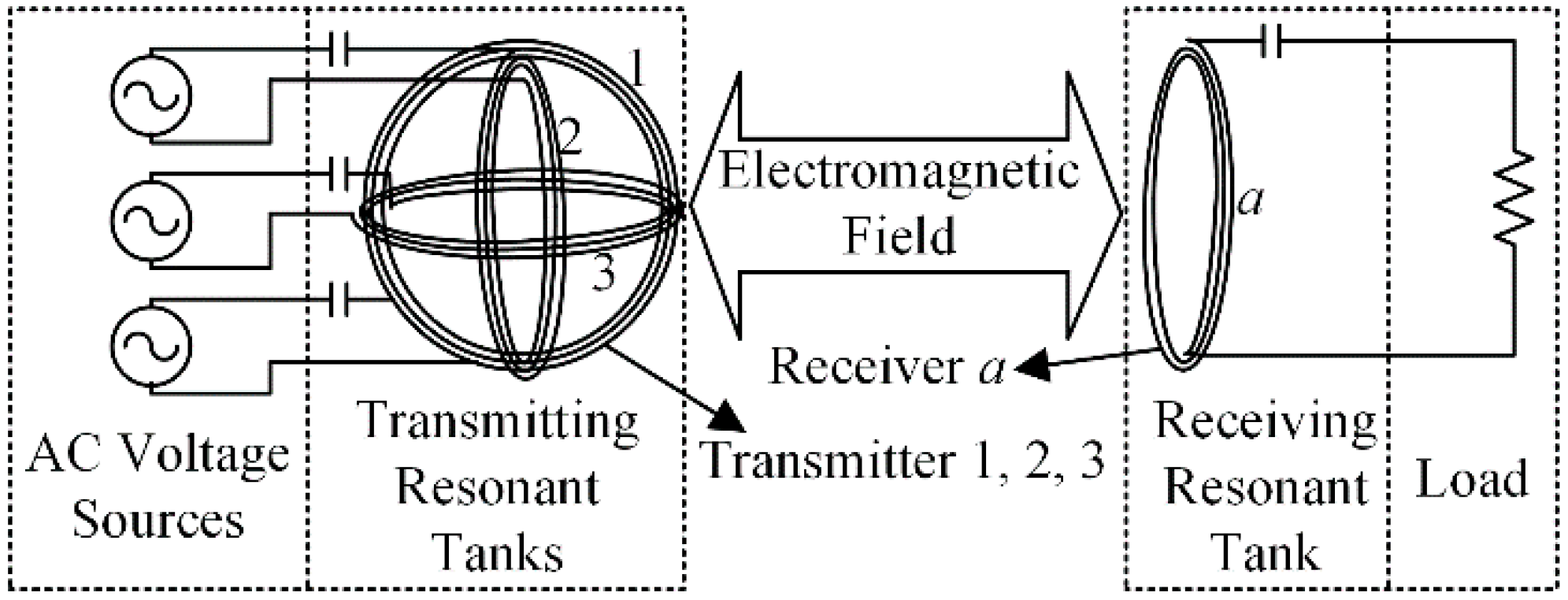
Figure 1 shows the arrangement of the three-phase-shifted drive omnidirectional WPT system. Three AC voltage sources whose phases are independently adjustable are respectively connected with the three transmitting coils. The three transmitting coils are pairwise orthogonal and co-centered, and all the coils are connected with a series capacitor to form a resonant tank. A capacitor is used to compensate the stray inductance of the transmitting and receiving coils which interact with each other via an electromagnetic field. For the sake of analysis, the transmitting resonant tanks and receiving resonant tank are named Resonator 1, 2, 3 and a, respectively.
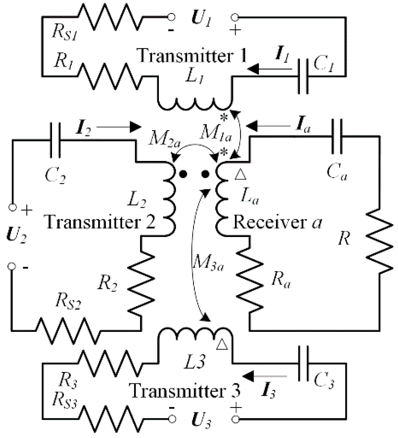
In this paper, bold italic letters are used to represent the phasors and italic letters are used to represent the real numbers and RMS values of the phasors. For example, I1 is a current phasor and I1 is the RMS value of I1. Figure 2 shows the lumped element circuit of the three-phase-shifted drive omnidirectional WPT system. According to the mutual inductance coupling theory, its circuit equations can be expressed in Equation (1).
where Xi is the reactance ωLi − 1/(ωCi), Li is the self-inductance, Ci is the compensating capacitance, Ii is the current, and Ri is the resistance in Resonator i (where i = 1, 2, 3, a); R is the load resistance; ω is the angular frequency of AC voltage source; Mja is the mutual inductance between transmitting coil j and receiving coil a (the mutual inductances of the three transmitting coils are zero theoretically and can be negligible in practice), Rsj is the source resistance, and Uj expressed in Equation (2) is the voltage source (where j = 1, 2, 3).
where, U0 is the RMS value of the AC voltage sources; β1, β2 and β3 are the phase angles of the corresponding excitation source.
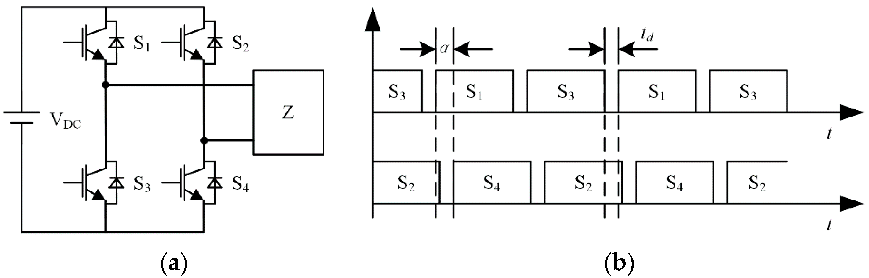
In the WPT system, as shown in Figure 3, the source resistance can be ignored using a full-bridge inverter as the system’s source, and the current of transmitting coil can be adjusted by the phase-shifted control of this inverter. In Figure 3a, VDC is the DC voltage source, Sj is the power switch (where j = 1, 2, 3, 4), Z is the equivalent load; in Figure 3b, td is the dead-time of the drive pulses for power switch, α is the phase-shifted angle, the range of α is from 0 to 2π (Note: α ∊ [π, 2π] refer to the phase-shifted operation after the reverse of the DC voltage source polarity and the operating phase-shifted angle is π − α). Then, the parameters in Equation (2) can be expressed as:
where, subscript i refers to the i-th inverter and i = 1, 2, 3.
The three transmitting coils can be designed into the same standard which means R1 = R2 = R3 = R0, and the resonators should be operated in resonance mode in order to maximize the power transfer capability. Thus, under the resonance mode (X1 = X2 = X3 = Xa = 0), the currents can be expressed into Equation (4) from Equations (1) and (2).
where, A = M1au1 + M2au3 + M3au3, , .
From Equations (2)–(4), if α1, α2 and α3 are all set as 0, the following equation should be met:
where, mi is the ratio of mutual inductance, ∆Ii = Ii − I0, I0 = U0/R0 is the RMS value of no-load current which is a constant in a certain WPT system due to the negligible variety of the DC voltage U0 and resistance R0, |∆I| = max{|∆Ii|}, sgn(∆I) = sgn(∆Ii), |M0| = max{|Mia|}, sgn(M0) = sgn(Mia) (where i = 1, 2, 3, a), |·| refers to calculate the absolute value of the parameter, max{·} refers to obtain the maximum value of the parameters set, sgn(·) refers to get the sign of the variable. Then, the defined system parameter MB can be identified as
where, , .
In the WPT system, the sign of the mutual inductance value depends on the directions of the transmitting and receiving coils’ reference currents which do not affect the power pickup of the load, and the mutual symbol relationships of the mutual inductance values can be identified by that of αi (i = 1, 2 and 3) from Equation (5). So, all the mutual inductance signs can be artificially adjusted to the same by adding the phase-shifted angle of corresponding full-bridge inverter as 2π. Then, the maximum efficiency transfer, the maximum power transfer, and the genuine omnidirectional power transfer can be realized if the three currents are set as Equation (7), and the values of the angle θ and φ can be set as Equation (8).
where, , i = 1, 2 and 3. Then, the maximum value of the overall power transfer efficiency for the WPT system can be expressed as:
where, RA = Ra + R is the total impedance of load resonant tank.
For the sake of manipulation in the WPT system, we follow these three points:
- (1)
- zero phase-shifted angle depends on ∆I, e.g., if ∆I = ∆I2, α2 = 0.
- (2)
- the minimum source polarity inverse principle, e.g., if , α3 = α3 + 2π.
- (3)
- define the parameter αdd as:
So, from Equations (4) and (7), let (i = 1, 2 and 3), the phase-shifted angles can be expressed as:
where
Substituting Equations (5), (6) and (8) into Equation (13), Equation (11) can be expressed as:
where is a known operator.
Equation (14) refers that the phase-shifted angles of the excitation sources for the omnidirectional WPT system can be easily calculated from the measured RMS current values of the three transmitting coils, then the maximum efficiency and power transfer can be achieved.
3. Mechanism of the Three-Phase-Shifted Drive Omnidirectional WPT System
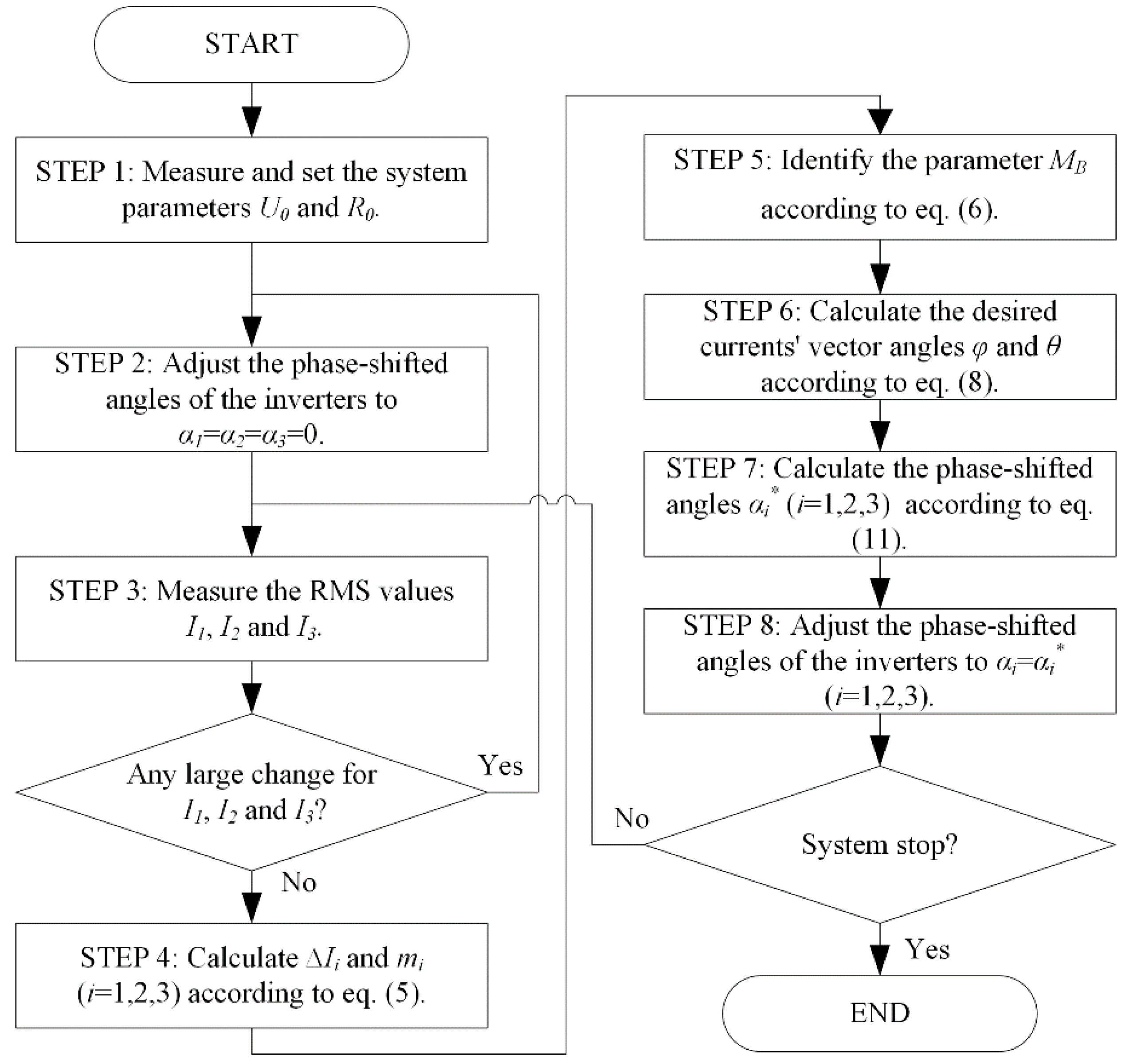
The analysis in Section 2 has important implications to the load power direction which is only the direction of the maximum transfer efficiency and load power at which the system will obtain maximum efficiency and the load will receive maximum power rather than the physical dimension (location and posture information) of the load itself. In order to achieve the omnidirectional pickup of the wireless power for a mobile load in this proposed WPT system, a real-time control flowchart is presented, as shown in Figure 4.
In Figure 4, the system initiation is STEP 1 which must be operated before the execution of the system; STEP 2 is the parameters initiation which is executed after each location and/or posture change of the receiving coil; based on the results of theoretical analysis in Section 2, STEP 3–7 are used to calculated the phase-shifted angles of the excitation sources; STEP 8 is executed to adjust the phase-shifted angles of the full-bridge inverters for maximizing the power transfer efficiency of the WPT system.
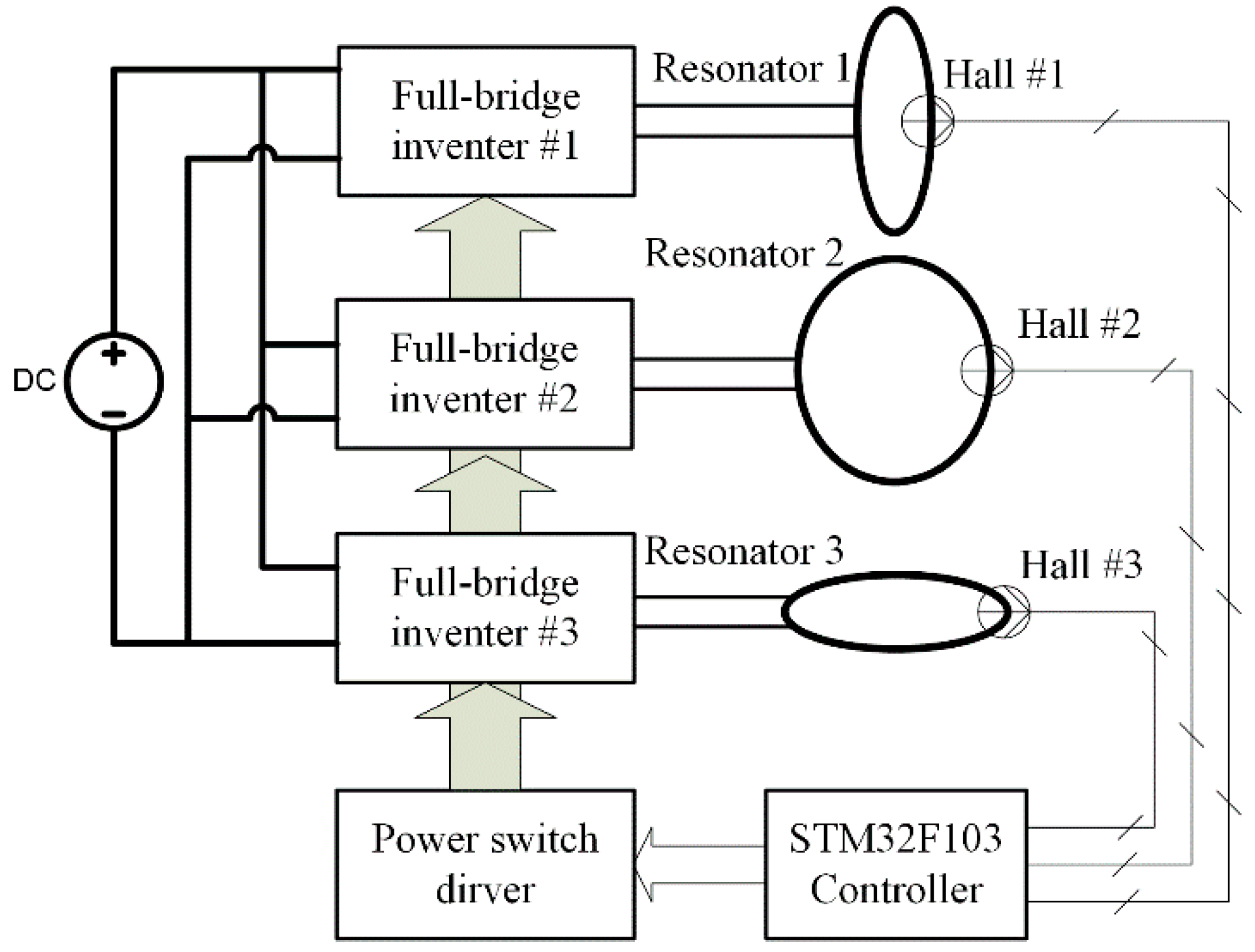
In order to implement the control flowchart in the experiments, an embedded control system is built to generate three channel adjustable phase-shifted pulse signals feeding the full-bridge inverters for power excitation, an external measuring and feedback control loop using hall sensors are used, as shown in Figure 5.
On the basis of Figure 4 and Figure 5, the real-time ability mainly depends on Equation (1) the settling time of WPT system, which is the time required for the transmitting coils’ currents to slew to the vicinity of the steady-state values when the phase-shifted angles of the inverters are all adjusted to zero, and Equation (2) the operation time, which is the time required for the microcontroller to calculate Equations (6), (8) and (11). These two parts of time are much smaller compared with the measuring and computing time of hundreds of practical voltage and current or the operation time required for the microcontroller to calculate high-order nonlinear equations shown previously [20]. That means the real-time ability of wireless power transmission for traveling load can be significantly improved based on the presented control mechanism.
4. Computer-Aided Analysis
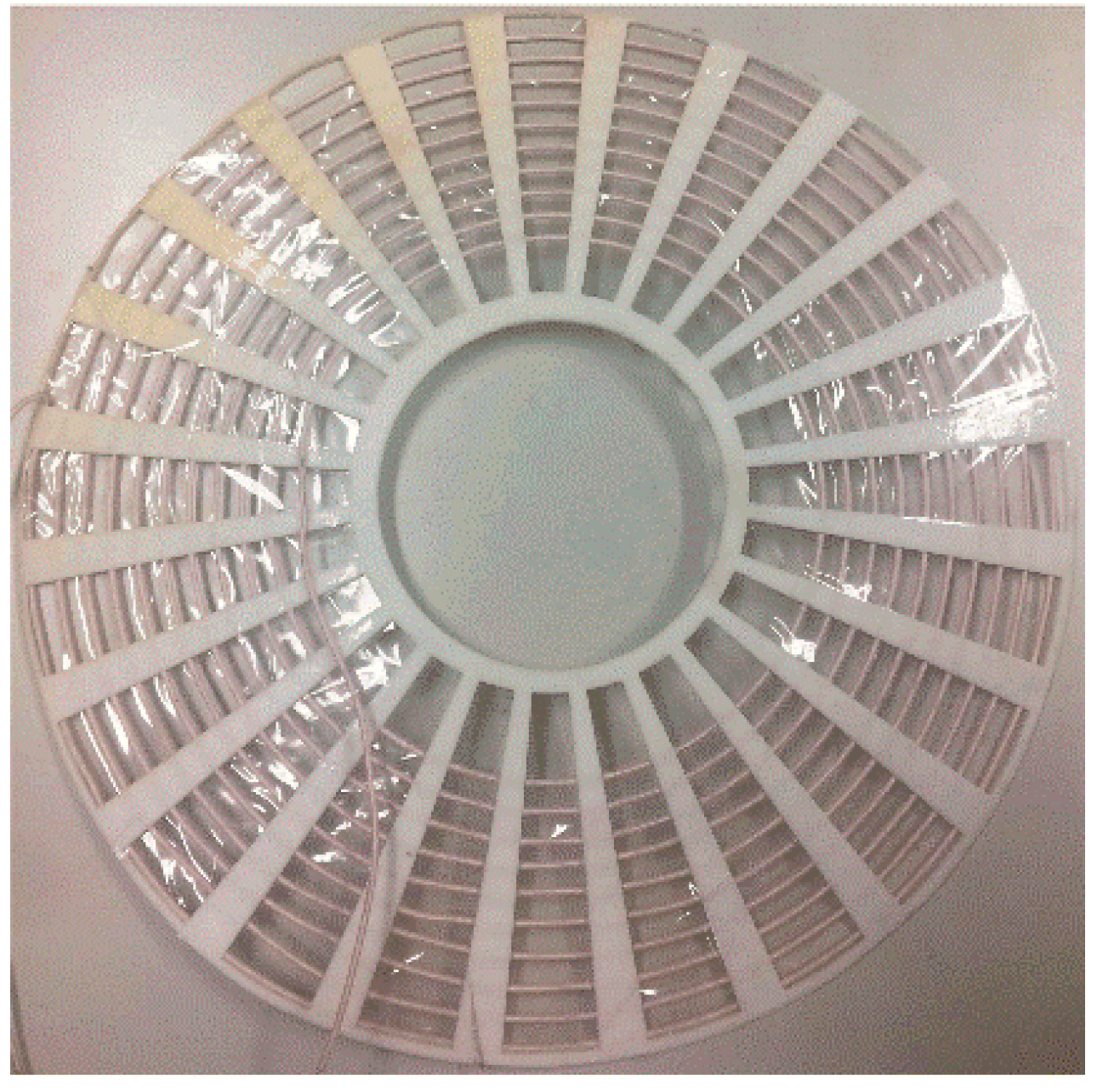
In this Section, MATLAB (R2017b, The MathWorks, Inc, Natick, MA, USA) simulation environment is used to verify the validity of the model and the mechanism of the three-phase-shifted drive omnidirectional WPT system. In these examples, the control flowchart shown in Figure 4 is employed for programming; the practical coil’s parameters are used in the simulation environment. The actual coil picture is shown in Figure 6 and the parameters are shown in Table 1. All the coils are the same and are made of litz wire which has 300 strands of No. 38 American wire gauge (AWG).
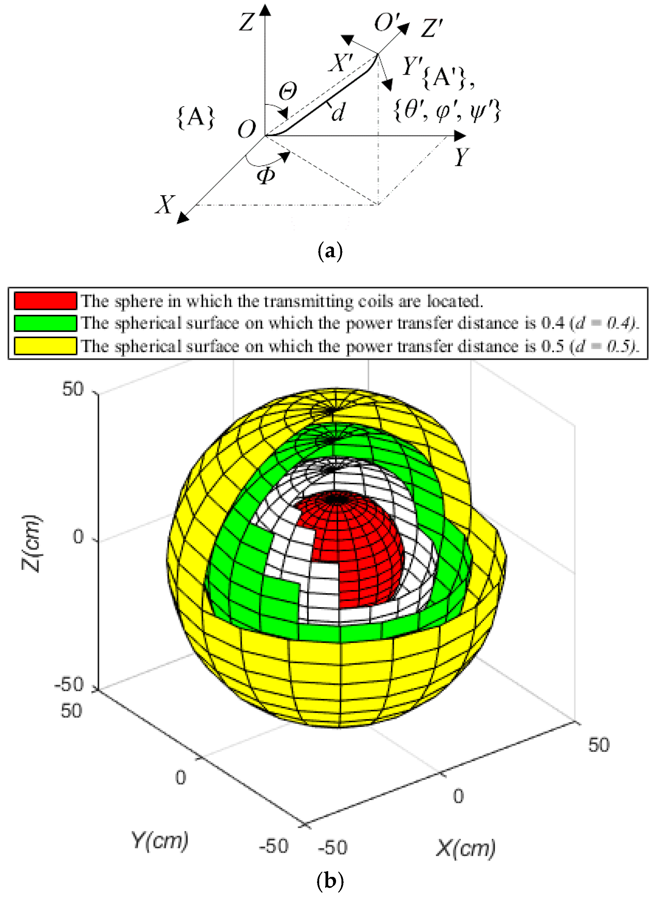
As shown in Figure 7a, the base coordinate system is {A} in which the three transmitting coils are orthogonally distributed in plane XOY, YOZ and ZOX respectively, the receiving coil is distributed in plane X′O′Y′ of the coordinate system {A′} which is established by the rotation and translation of {A}, and the transformation steps are described as: (1) rotate anticlockwise θ′, φ′, and ψ′ based on axis X, Y and Z, respectively, (2) transit d·sinΘ·cosΦ, d·sinΘ·sinΦ and d·cosΘ along axis X, Y and Z, respectively. Where symbol d represents the power transfer distance. The power transmission space of omnidirectional WPT system is divided into different subspaces as shown in Figure 7b.
In the MATLAB simulation model, the operating frequency and the power transfer distance are set at 200 kHz and 0.4 m, respectively. The simulation examples aim at the different locations and postures of the receiving coil, and the random sampling method is used to set the locations and postures of coils.
4.1. On the Tangent Plane of the Green Spherical Surface
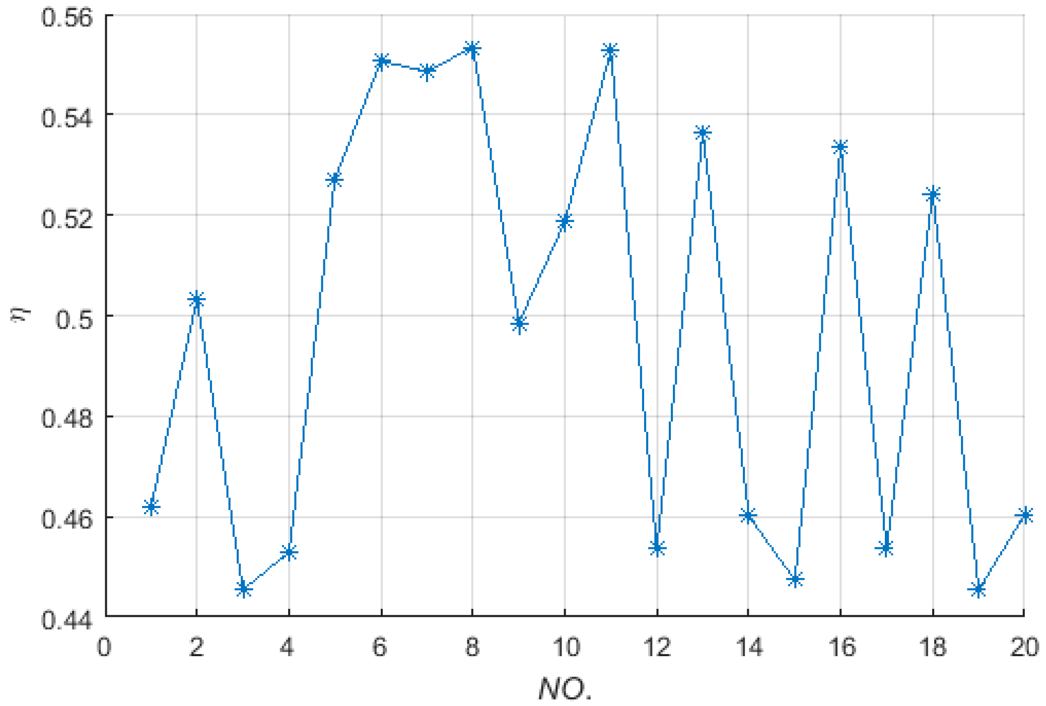
In this example, the receiving coil is set on the tangent plane of the green spherical surface, as shown in Figure 7b. The random sampling values of (Θ, Φ) are shown in Table 2 (where “NO.” represents the number of simulation experiments, the same below in this Section), and the corresponding power transfer efficiencies are shown in Figure 8.
As can be seen in Figure 8, the simulated results show: (1) the power transfer efficiency is about 50% at all the locations of the randomly distributed receiving coil; (2) the difference between the maximum value and the minimum value of the efficiency is within the scope of twelve percentage points. Which means if the receiving coil moves on the sphere and keeps the radial direction of the sphere as its normal direction, high and stable power transfer efficiency can be obtained.
4.2. On the Green Spherical Surface with Different Postures
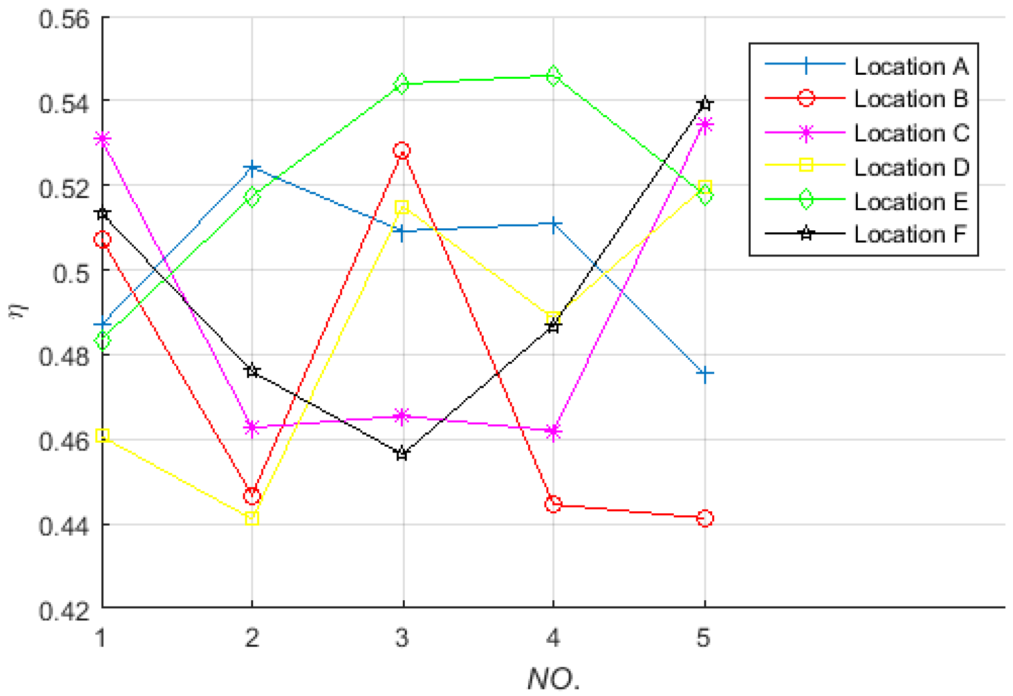
In this example, the receiving coil is set on the green spherical surface shown in Figure 7b with different postures. Six sets of parameter set (Θ, Φ) have been randomly selected from Part 1 of this Section, and with each set (marked as a location), the random sampling number of the parameter set (θ′, φ′, ψ′) is set to five. The values of parameter set (Θ, Φ, θ′, φ′, ψ′) are shown in Table 3, and the corresponding power transfer efficiencies are shown in Figure 9.
As can be seen from Figure 9, the simulated results show: (1) the power transfer efficiency is about 50% at all the locations of randomly distributed receiving coil with random postures; (2) the power transfer efficiency exists difference when the receiving coil locates at the same location with different postures; (3) the difference between the maximum value and the minimum value of the efficiency is also within the scope of twelve percentage points. Which means if the receiving coil moves and rotates on the sphere, high and stable power transfer efficiency can also be obtained.
4.3. In the Spherical Shell with Different Locations and Postures
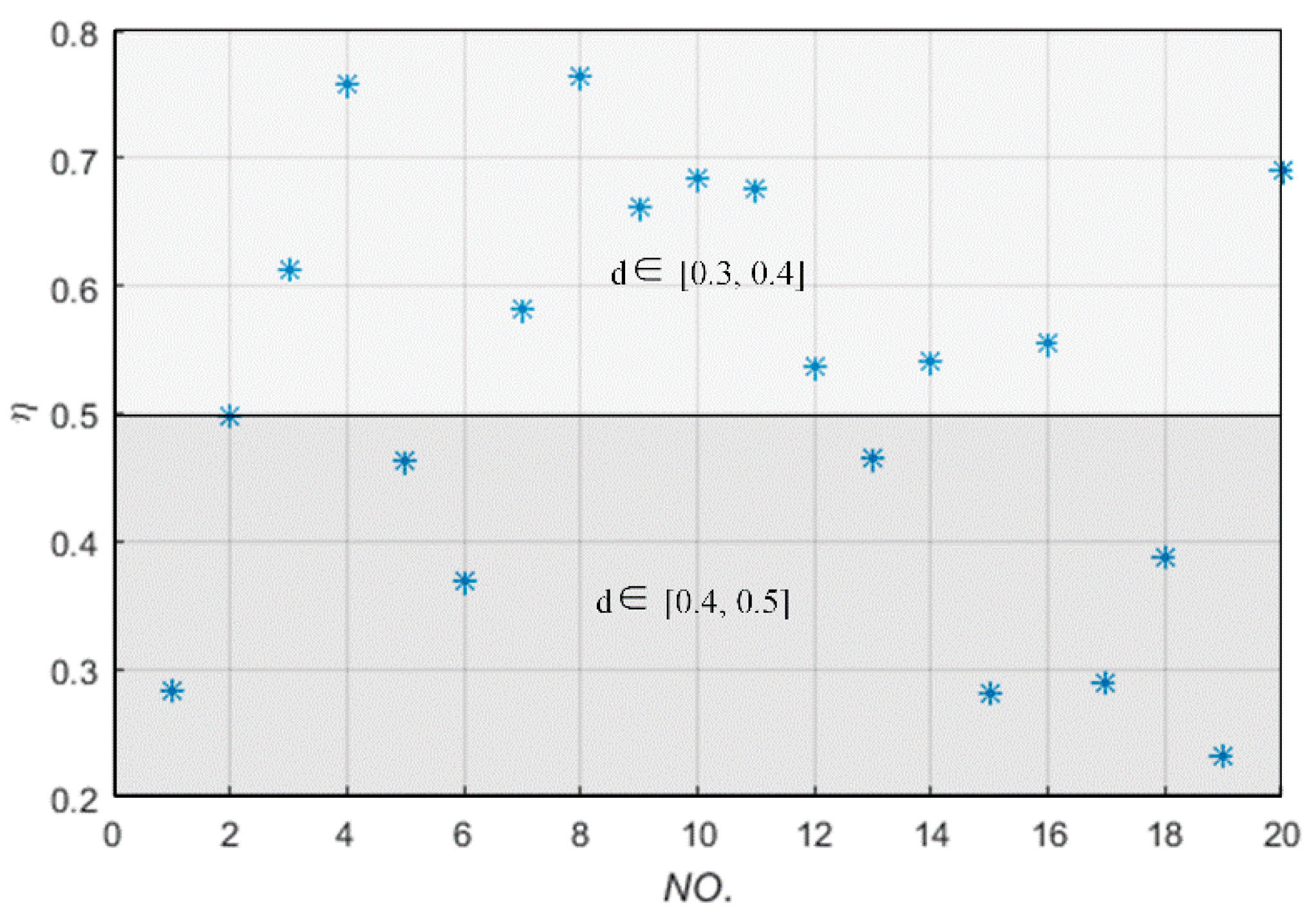
In this simulation, the receiving coil is set in the spherical shell whose internal surface color and outside surface color are white and yellow, respectively, as shown in Figure 7b. The parameter set (Θ, Φ, θ′, φ′, ψ′) has been set in the range of [−180°, 180°] and parameter d has been taken in the range of [0.3, 0.5], and the total sample number is 20. The values of parameter set (d, Θ, Φ, θ′, φ′, ψ′) are shown in Table 4, and the corresponding power transfer efficiencies are shown in Figure 10.
In Figure 10, d ∊ [0.3, 0.4] indicates that the receiving coil is set in the spherical shell whose internal surface color and outside surface color are respectively white and green, and d ∊ [0.4, 0.5] indicates that the receiving coil is set in the spherical shell whose internal surface color and outside surface color are green and yellow, respectively, as shown in Figure 7b. Meanwhile, Figure 10 shows (1) the power transfer efficiency is more than 50% with the transfer distance less than 0.4 m even though the receiving coil randomly moves and rotates in the spherical domain; (2) the main influence factor of the power transfer efficiency is not the posture (except some bad case scenarios shown in the Part 2 of Section 5) but the location of the receiving coil in this WPT system; (3) a certain power transfer efficiency can be obtained even though the receiving coil moves and rotates in the three-dimensional space.
4.4. On the Green Spherical Surface with Different Locations and Postures
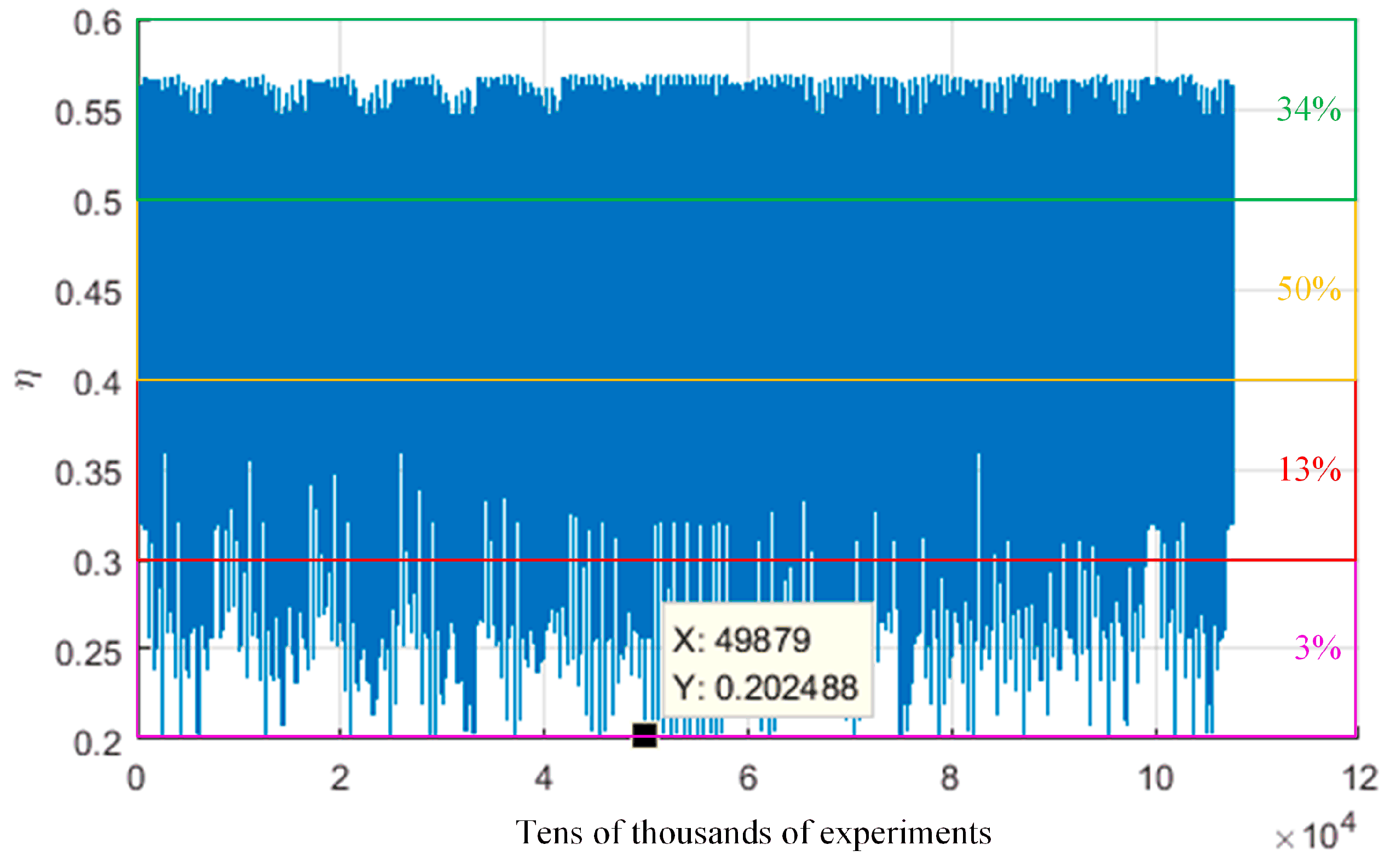
In this simulation, the nested and exhaustive algorithm has been used to study these five parameters Θ, Φ, θ′, φ′ and ψ′ which are effecting the power transfer efficiency. The interval value of each parameter in this algorithm is 15°, and the value ranges of the first two parameters and the last three parameters are (0, 90°) and (0, 180°), respectively. So the total number of simulation iteration is 107,653 and the corresponding power transfer efficiencies are shown in Figure 11.
Figure 11 shows: (1) in the whole spherical surface, the location and posture of the receiving coil taken together, the number ratios of four power transfer efficiency levels (20%, 30), (30%, 40%), (40%, 50%) and (50%, 60%) are 3%, 13%, 50% and 34%, respectively; (2) there are some bad case scenarios shown in the area of lower power transfer efficiency which is lower than 25%; (3) one of the worst case scenarios’ parameters are that of the 49879th simulation time and the corresponding location and posture values are Θ = 90°, Φ = 45°, θ′ = 90°, φ′ = 0°, ψ′ = 45°.
5. Practical Verification
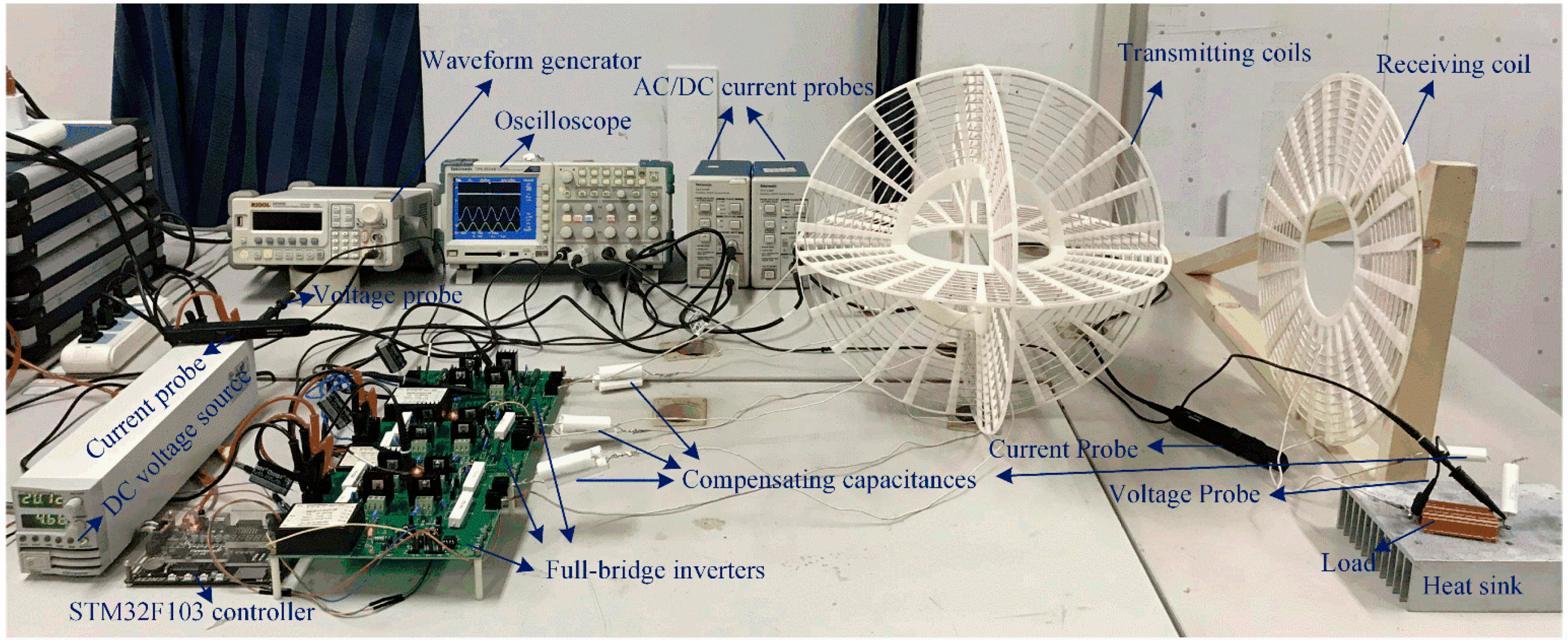
Some experiments have been conducted to verify the theoretical results in Section 3 and the simulated results in Section 4. A practical setup of three-phase-shifted drive omnidirectional wireless power transfer system is shown in Figure 12. The coils’ parameters used for the experiments are shown in Table 1, the electrical parameters of the coils are measured by using the Inductance Capacitance Resistance (LCR) digital electric bridge (ZX8526A) (Changzhou Zhixin Precision Electronics Co., Ltd., Changzhou, China) and are listed in Table 5. The measured values of tuning capacitances are C1 = 15.6 nF, C2 = 15.5 nF, C3 = 15.5 nF and Ca = 15.7 nF, respectively. The distance between the centers of the transmitting coil and the receiving coil is d = 0.4 m.
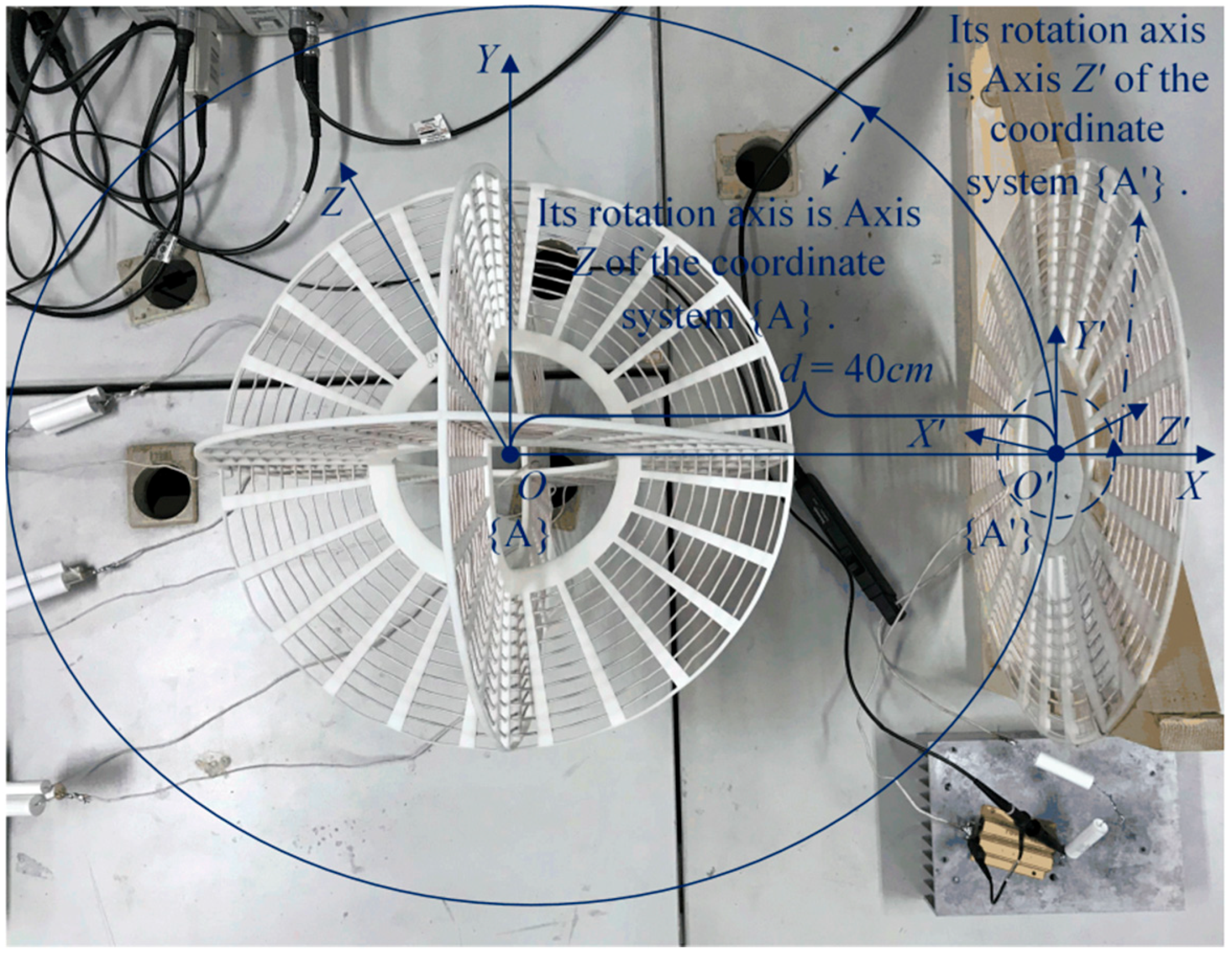
The schematic diagram of experimental condition is shown in Figure 13, where the solid line and the dotted line respectively represent the receiving coil’s movement trajectory in the plane XOY and the rotation trajectory along Axis Z′, and the initial center location and posture of the receiving coil are (90°, 0) (which indicates the point (0.4 m, 0, 0) in {A}) and (0, 90°, 0) respectively. A high-speed digital oscilloscope (TPS2024B, 200 MHz bandwidth) (Tektronix Inc., Beaverton, OR, USA) is used to record the input/output voltage and current waveforms of the system and the drive pulses of Metal-Oxide -Semiconductor Field Effect Transistor (MOSFET) in the full-bridge inverter.
5.1. On the Tangent Plane of the Green Spherical Surface
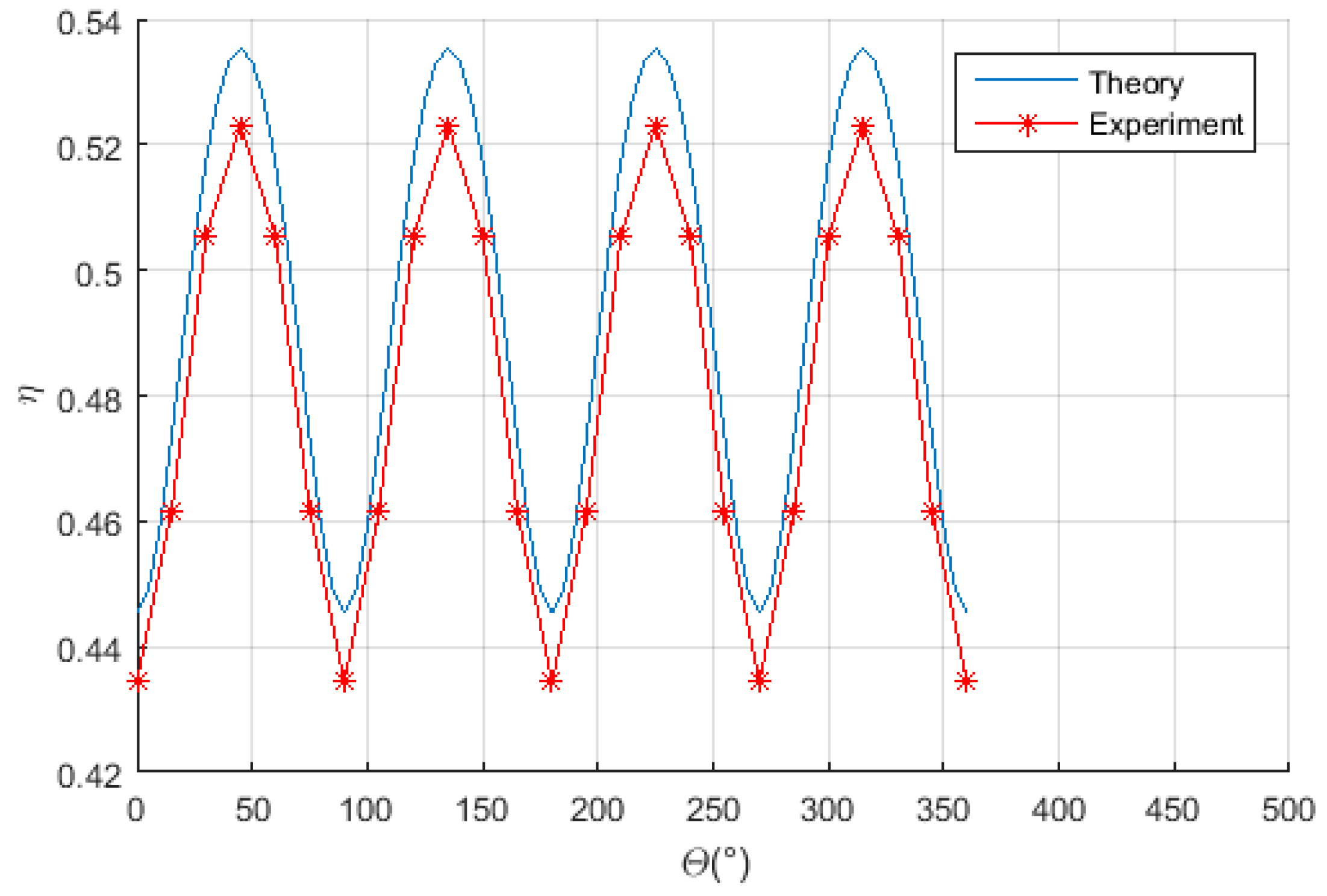
When the receiving coil keeps its normal direction along the radial direction of the sphere in the experimental process which starts at the initial location and moves along the solid line shown in Figure 13 which represents a circle on the green spherical surface as shown in Figure 7b of Section 4, the power transfer efficiency is measured and plotted in Figure 14. As can be seen from Figure 14, the experimental results agree well with the theoretical values, and the measured efficiency can be maintained at about 48% within ±5% error band.
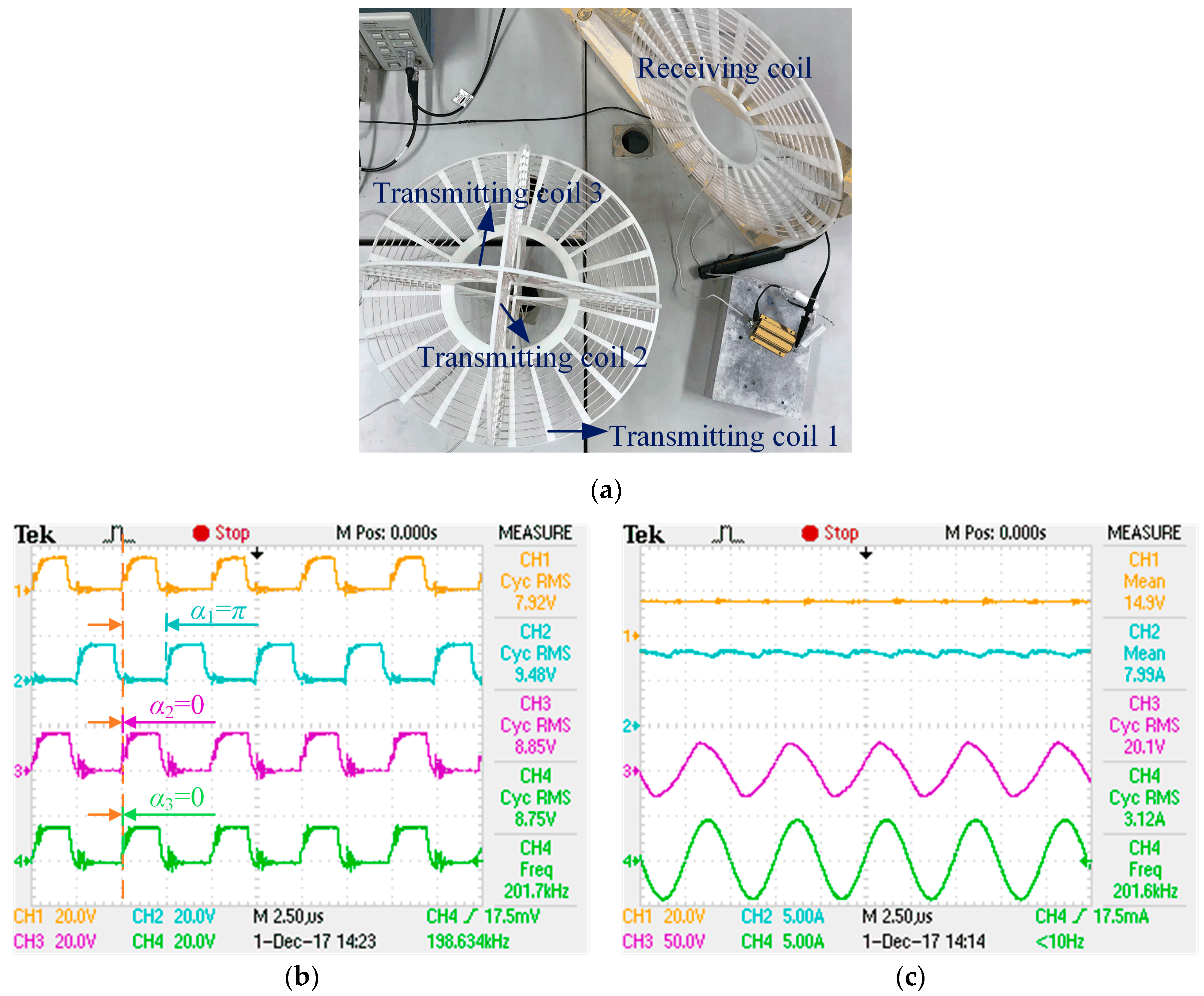
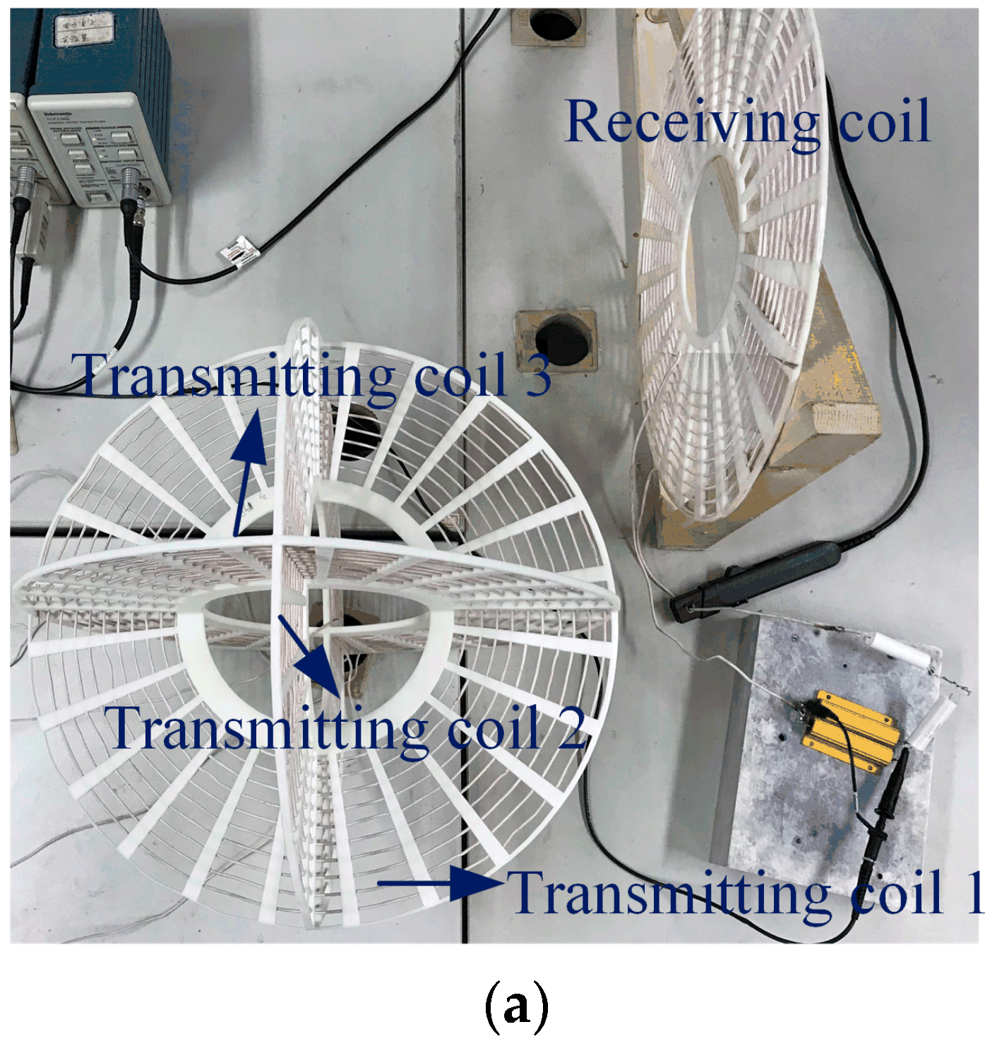
When the center location and posture of the receiving coil are adjusted at (90°, 45°) (which indicates the point (0.28 m, 0.28 m, 0 m) in {A}) and (0, 90°, 45°) shown in Figure 15a, the phase-shifted drive pulses of MOSFET must be set using Figure 15b, where CH1, CH2, CH3 and CH4 represent standard drive pulses, phase-shifted drive pulses of excitation source 1, 2 and 3, respectively. Then the input voltage and current, output voltage and current waveforms are measured by CH1, CH2, CH3 and CH4 shown in Figure 15c.
As we can see from Figure 15a, the transmitting coil 1 and receiving coil are mutual orthogonal, and the pose relationship between the transmitting coil 2 and receiving coil is equivalent to that of transmitting coil 3 and the receiving coil, so the phase-shifted angles of these three excitation sources are respectively π, 0 and 0, shown in Figure 15b. In which, the resultant magnetic vector could maximally point at the receiving coil and the maximum power transfer efficiency can be achieved. As shown in Figure 15c, with the output power of 62.7 W, the transfer efficiency and operating frequency are 52.3% and 201.6 kHz, respectively, which agrees well with the theoretical values 53.5% and 202 kHz.
5.2. On the Green Spherical Surface with Different Postures
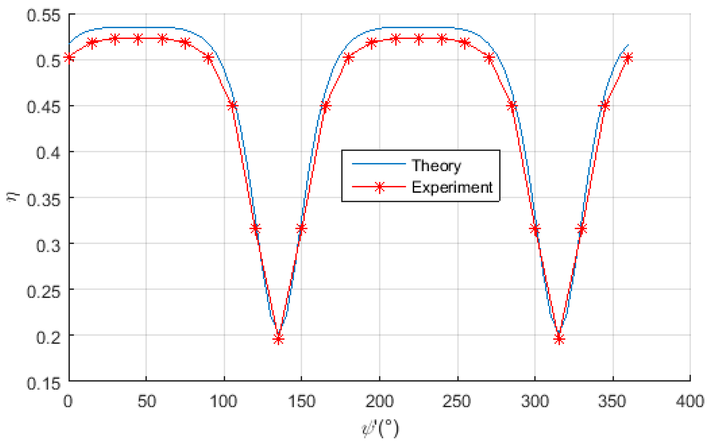
When the center location of receiving coil is adjusted at (90°, 45°) and rotates along Axis Z′ in a circle, the power transfer efficiency is measured and plotted in Figure 16, which indicates that the experimental results agree well with the theoretical values, and the measured power transfer efficiency can be maintained at more than 50% in most cases; the efficiency is insensitive to the posture of receiving coil in these case scenarios.
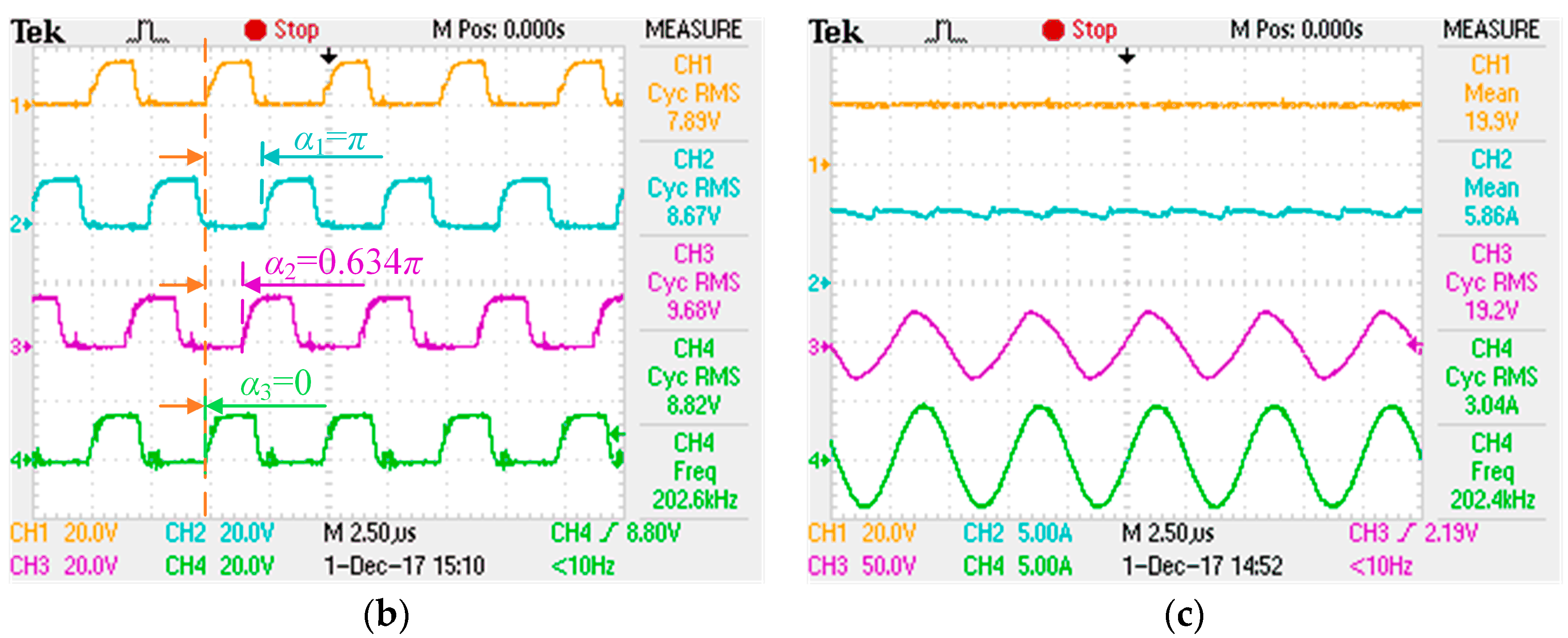
When the center location of receiving coil is adjusted at (90°, 45°) (which indicates the point (0.28 m, 0.28 m and 0 m) in {A}) and the posture is set at (0, 90°, 0°), which are shown in Figure 17a, the phase-shifted drive pulses of MOSFET must be set as Figure 17b, where CH1, CH2, CH3 and CH4 represent standard drive pulses, phase-shifted drive pulses of excitation source 1, 2 and 3, respectively. Then the input voltage and current, output voltage, and current waveforms are measured by CH1, CH2, CH3 and CH4, shown in Figure 17c.
As we can see from Figure 17a, the transmitting coil 1 and receiving coil are mutual orthogonal, and the interaction between transmitting coil 3 and receiving coil is stronger than that of the transmitting coil 2 and the receiving coil, so the calculated phase-shifted angles of these three excitation sources are π, 0.634π and 0, respectively, shown in Figure 17b. In which, the resultant magnetic vector could also maximally point at the receiving coil; the maximum power transfer efficiency can also be achieved in this experiment. As shown in Figure 17c, with the output power of 58.3 W, the transfer efficiency and operating frequency are respectively 50.0% and 202.4 kHz which agree well with the theoretical values 51.7% and 202 kHz.
5.3. In the Spherical Shell with Different Locations and Postures
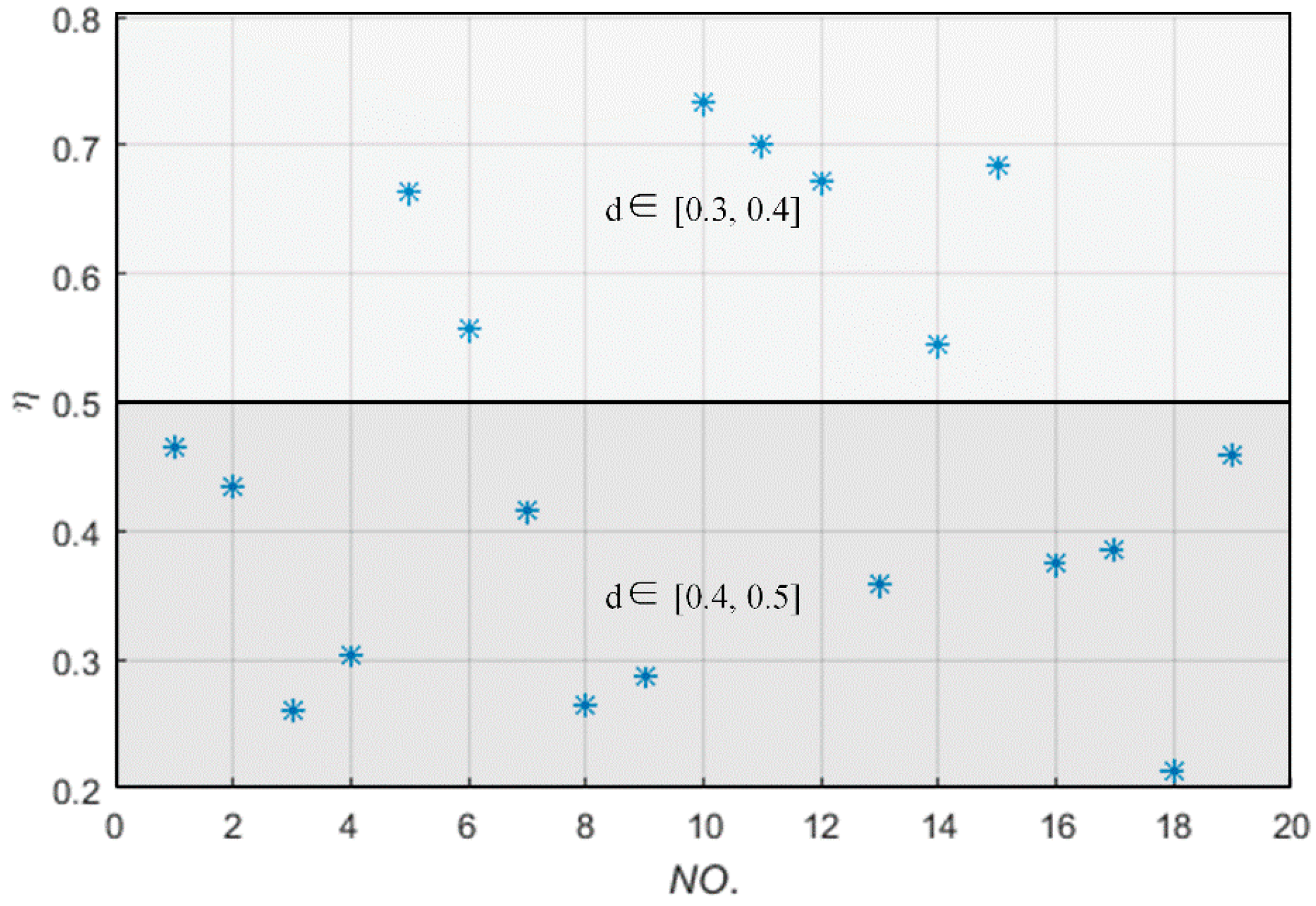
When the receiving coil randomly moves and postures in the spherical shell, whose inner and outer radius are 0.3 m and 0.5 m, respectively, and whose internal surface color and outside surface color are white and yellow, respectively, as shown in Figure 7b of Section 4. The power transfer efficiency is measured and plotted in Figure 18, where the abscissa “NO.” represents the times of measurement, d ∊ [0.3, 0.4] indicates that the receiving coil is set in the spherical shell whose internal surface color and outside surface color are white and green, respectively, and d ∊ [0.4, 0.5] indicates that the receiving coil is set in the spherical shell whose internal surface color and outside surface color are green and yellow, respectively, as shown in Figure 7b. Figure 18 indicates that the measured power transfer efficiencies agree well with that of the simulation results shown in Part 3 of Section 4.
When the posture parameters of the receiving coil are adjusted at one of the worst case scenarios (Θ = 90°, Φ = 45°, θ′ = 90°, φ′ = 0°, ψ′ = 45°), shown in Part 4 of Section 4 and Figure 19a, the phase-shifted drive pulses of MOSFET must be set as shown in Figure 19b, where CH1, CH2, CH3 and CH4 represent standard drive pulses and phase-shifted drive pulses of excitation source 1, 2 and 3, respectively. Then the input voltage and current, output voltage, and current waveforms are measured by CH1, CH2, CH3 and CH4, shown in Figure 19c.
As we can see from Figure 19a, the transmitting coil 1 and receiving coil are mutual orthogonal, and the mutual inductance between transmitting coil 2 and the receiving coil is opposite to that of transmitting coil 3 and the receiving coil, so the calculated phase-shifted angles of these three excitation sources are π, 0 and 2π, respectively, as shown in Figure 19b. In which, the resultant magnetic vector could also maximally point at the receiving coil; the maximum power transfer efficiency can also be achieved in this experiment. As shown in Figure 19c, with an output power of 22.7 W, the transfer efficiency and operating frequency are 19.1% and 201.4 kHz, respectively, which agrees well with the theoretical values 20.2% and 202 kHz.
6. Conclusions
This paper describes a novel wireless power transfer system, in which the three-phase-shifted drive mechanism has been deployed to realize the whole-space transmission and pickup of the energy. The corresponding theory and control method have been presented and practically proven on a hardware prototype. This system is envisaged to be an elegant solution to achieve the omnidirectional transfer of the electric energy.
In this proposed omnidirectional WPT system, the power transfer efficiency depends mainly on the distance between the excitation coil and the receiving coil, while the influence of the receiving coil’s posture is a secondary consideration in most case scenarios. Meanwhile, the control mechanism employs two measurements of the currents’ RMS values of the three transmitting coils and simple calculations after each location and/or posture change of the receiving coil, which greatly improves the real-time ability of wireless power transmission for traveling load compared with the existing control mechanisms of the omnidirectional WPT system. So, this system is suitable for the areas requiring of real-time and multiple degree of freedom for the load, such as the wireless charging areas of underwater robots, automated guided vehicle, and wall-mounted mobile TV, etc. Based on the presented theoretical foundation and control mechanism for the omnidirectional WPT system, the dimensions of the coils can be optimized for the applications of medium and small power areas such as the areas of smartphone, PAD and medical implants, etc.; research on its optimization method could be carried out in future.
Author Contributions
Conceptualization, Z.Y. and Y.S.; Methodology, Z.Y.; Software, P.W.; Validation, Z.Y. and P.W.; Formal Analysis, Y.S. and X.L.; Investigation, X.L.; Writing-Original Draft Preparation, Z.Y.; Writing-Review & Editing, P.W., C.T. and H.T.; Supervision, Y.S.; Project Administration, X.L. and C.T.; Funding Acquisition, C.T. and H.T. All authors have contributed to the editing and proofreading of this paper.
Funding
This research was funded by Research on Wireless Sensing and Measurement Technology of Solar Cell Wing Mechanism Performance in Space Environment: (6140003030201), and National Natural Science Foundation of China (61573074).
Conflicts of Interest
The authors declare no conflict of interest.
References
- Park, C.; Lee, S.; Jeong, S.Y.; Cho, G.H.; Rim, C.T. Uniform Power I-Type Inductive Power Transfer System with DQ-Power Supply Rails for On-Line Electric Vehicles. IEEE Trans. Power Electron. 2015, 30, 6446–6455. [Google Scholar] [CrossRef]
- Mi, C.C.; Buja, G.; Choi, S.Y.; Rim, C.T. Modern Advances in Wireless Power Transfer Systems for Roadway Powered Electric Vehicles. IEEE Trans. Ind. Electron. 2016, 63, 6533–6545. [Google Scholar] [CrossRef]
- Kikuchi, S.; Sakata, T.; Takahashi, E.; Kanno, H. Development of Wireless Power Transfer System for Robot Arm with Rotary and Linear Movement. In Proceedings of the 2016 IEEE International Conference on Advanced Intelligent Mechatronics (AIM), Banff, AB, Canada, 12–15 July 2016; pp. 1616–1621. [Google Scholar]
- Hasan, N.; Cocar, I.; Amely, T.; Wang, H.; Zane, R.; Pantic, Z.; Bodine, C. A Practical Implementation of Wireless Power Transfer Systems for Socially Interactive Robots. In Proceedings of the 2015 IEEE Energy Conversion Congress and Exposition (ECCE), Montreal, QC, Canada, 20–24 September 2015; pp. 4935–4942. [Google Scholar]
- Tang, S.C.; Lun, T.L.T.; Guo, Z.; Kwok, K.W.; McDannold, N.J. Intermediate Range Wireless Power Transfer with Segmented Coil Transmitters for Implantable Heart Pumps. IEEE Trans. Power Electron. 2016, 32, 3844–3857. [Google Scholar] [CrossRef]
- Ahn, D.; Ghovanloo, M. Optimal Design of Wireless Power Transmission Links for Millimeter-Sized Biomedical Implants. IEEE Trans. Biomed. Circuits Syst. 2016, 10, 125–137. [Google Scholar] [CrossRef] [PubMed]
- Raval, P.; Kacprzak, D.; Hu, A.P. A wireless power transfer system for low power electronics charging applications. In Proceedings of the 2011 6th IEEE Conference on Industrial Electronics and Applications, Beijing, China, 21–23 June 2011; pp. 520–525. [Google Scholar]
- Pellitteri, F.; Boscaino, V.; di Tommaso, A.O. Inductive power transfer for 100 W battery charging. In Proceedings of the IECON 2013—39th Annual Conference of the IEEE Industrial Electronics Society, Vienna, Austria, 10–13 November 2013; pp. 894–899. [Google Scholar]
- Chabalko, M.J.; Sample, A.P. Three-Dimensional Charging via Multimode Resonant Cavity Enabled Wireless Power Transfer. IEEE Trans. Power Electron. 2015, 30, 6163–6173. [Google Scholar] [CrossRef]
- Lee, E.S.; Choi, B.H.; Sohn, Y.H.; Lim, G.C.; Rim, C.T. Multiple Dipole Receiving Coils for 2-D Omnidirectional Wireless Mobile Charging under Wireless Power Zone. In Proceedings of the 2015 IEEE Energy Conversion Congress and Exposition (ECCE), Montreal, QC, Canada, 20–24 September 2015; pp. 3209–3214. [Google Scholar]
- Lin, D.; Zhang, C.; Hui, S.Y.R. Mathematic Analysis of Omnidirectional Wireless Power Transfer—Part-I: Two-Dimensional Systems. IEEE Trans. Power Electron. 2017, 32, 625–633. [Google Scholar] [CrossRef]
- Che, B.J.; Meng, F.Y.; Lyu, Y.L.; Zhu, W.L.; Zhang, K.; Yang, G.H.; Fu, J.H.; Zhu, L.; Wu, Q.; Sun, L. Omnidirectional wireless power transfer system supporting mobile devices. Appl. Phys. A 2016, 122, 54. [Google Scholar] [CrossRef]
- Kim, T.H.; Yun, G.H.; Lee, W.Y.; Yook, J.G. Asymmetric Coil Structures for Highly Efficient Wireless Power Transfer Systems. IEEE Trans. Microw. Theory Tech. 2018, 66, 3443–3451. [Google Scholar] [CrossRef]
- Kim, T.H.; Yoon, S.; Yook, J.G.; Yun, G.H.; Lee, W.Y. Evaluation of power transfer efficiency with ferrite sheets in WPT system. In Proceedings of the 2017 IEEE Wireless Power Transfer Conference (WPTC), Taipei, Taiwan, 10–12 May 2017; pp. 1–4. [Google Scholar]
- Jonah, O.; Georgakopoulos, S.V.; Tentzeris, M.M. Orientation insensitive power transfer by magnetic resonance for mobile devices. In Proceedings of the 2013 IEEE Wireless Power Transfer (WPT), Perugia, Italy, 15–16 May 2013; pp. 5–8. [Google Scholar]
- Choi, B.H.; Lee, E.S.; Sohn, Y.H.; Kim, J.H.; Rim, C.T. Crossed Dipole Coils for an Omnidirectional Wireless Power Zone with DQ Rotating Magnetic Field. In Proceedings of the 2015 IEEE Energy Conversion Congress and Exposition (ECCE), Montreal, QC, Canada, 20–24 September 2015; pp. 2261–2268. [Google Scholar]
- Wang, D.; Zhu, Y.; Zhu, Z.; Mo, T.T.; Huang, Q. Enabling multi-angle wireless power transmission via magnetic resonant coupling. In Proceedings of the 2012 7th International Conference on Computing and Convergence Technology (ICCCT), Seoul, Korea, 3–5 December 2012; pp. 1395–1400. [Google Scholar]
- Zhang, C.; Lin, D.; Hui, S.Y. Basic Control Principles of Omnidirectional Wireless Power Transfer. IEEE Trans. Power Electron. 2016, 31, 5215–5227. [Google Scholar]
- Ng, W.; Zhang, C.; Lin, D.; Hui, S.Y.R. Two- and Three-Dimensional Omni-Directional Wireless Power Transfer. IEEE Trans. Power Electron. 2014, 29, 4470–4474. [Google Scholar] [CrossRef]
- Lin, D.; Zhang, C.; Hui, S.Y.R. Mathematic Analysis of Omnidirectional Wireless Power Transfer—Part-II Three-Dimensional Systems. IEEE Trans. Power Electron. 2017, 32, 613–624. [Google Scholar] [CrossRef]
Figure 1.
Typical three-phase-shifted drive omnidirectional wireless power transfer (WPT) system.

Figure 2.
Lumped circuit model of the three-phase-shifted drive omnidirectional WPT system.

Figure 3.
A typical topology of the excitation power source: (a) the topology of inverter; (b) the drive pulses of power switches.
Figure 3.
A typical topology of the excitation power source: (a) the topology of inverter; (b) the drive pulses of power switches.

Figure 4.
The control flowchart of the three-phase-shifted drive omnidirectional WPT system.

Figure 5.
Schematic of the experimental setup.

Figure 6.
Photograph of the practical coil.

Figure 7.
The coordinate system and power transmission space of omnidirectional WPT system: (a) center relationship between the transmitting coils and the receiving coil and (b) space division.
Figure 7.
The coordinate system and power transmission space of omnidirectional WPT system: (a) center relationship between the transmitting coils and the receiving coil and (b) space division.

Figure 8.
The power transfer efficiency versus the receiving coil distributed on the different tangent plane of the green spherical surface (radius is 0.4 m).
Figure 8.
The power transfer efficiency versus the receiving coil distributed on the different tangent plane of the green spherical surface (radius is 0.4 m).

Figure 9.
The power transfer efficiency versus the receiving coil with different locations and postures on the green spherical surface (radius is 0.4 m).
Figure 9.
The power transfer efficiency versus the receiving coil with different locations and postures on the green spherical surface (radius is 0.4 m).

Figure 10.
The power transfer efficiency versus the receiving coil with different locations and postures in the spherical shell.
Figure 10.
The power transfer efficiency versus the receiving coil with different locations and postures in the spherical shell.

Figure 11.
The power transfer efficiency versus the times of nested simulation.

Figure 12.
Practical setup of the three-phase-shifted drive omnidirectional WPT system.

Figure 13.
The schematic diagram of experimental condition.

Figure 14.
The power transfer efficiency versus the receiving coil moving along the solid line.

Figure 15.
Practical measurements in the conditions Θ = 90°, Φ = 45°, θ′ = 0°, φ′ = 90°, ψ′ = 45° and d = 0.4 m. (a) Locations and postures of system coils; (b) phase-shifted drive pulses; (c) input/output voltage and current waveforms.
Figure 15.
Practical measurements in the conditions Θ = 90°, Φ = 45°, θ′ = 0°, φ′ = 90°, ψ′ = 45° and d = 0.4 m. (a) Locations and postures of system coils; (b) phase-shifted drive pulses; (c) input/output voltage and current waveforms.

Figure 16.
The power transfer efficiency versus the receiving coil rotating along the dotted line at the location (0.28 m, 0.28 m and 0 m).
Figure 16.
The power transfer efficiency versus the receiving coil rotating along the dotted line at the location (0.28 m, 0.28 m and 0 m).

Figure 17.
Practical measurements in the conditions Θ = 90°, Φ = 45°, θ′ = 0°, φ′ = 90°, ψ′ = 0° and d = 0.4 m. (a) Locations and postures of system coils; (b) phase-shifted drive pulses; (c) input/output voltage and current waveforms.
Figure 17.
Practical measurements in the conditions Θ = 90°, Φ = 45°, θ′ = 0°, φ′ = 90°, ψ′ = 0° and d = 0.4 m. (a) Locations and postures of system coils; (b) phase-shifted drive pulses; (c) input/output voltage and current waveforms.


Figure 18.
The power transfer efficiencies versus the receiving coil moving and rotating in the spherical shell.
Figure 18.
The power transfer efficiencies versus the receiving coil moving and rotating in the spherical shell.

Figure 19.
Practical measurements in the conditions Θ = 90°, Φ = 45°, θ′ = 90°, φ′ = 0°, ψ′ = 45° and d = 0.4 m. (a) Locations and postures of system coils; (b) phase-shifted drive pulses; (c) input/output voltage and current waveforms.
Figure 19.
Practical measurements in the conditions Θ = 90°, Φ = 45°, θ′ = 90°, φ′ = 0°, ψ′ = 45° and d = 0.4 m. (a) Locations and postures of system coils; (b) phase-shifted drive pulses; (c) input/output voltage and current waveforms.


Table 1.
Parameters of a practical coil.
| Parameters | Symbol | Value |
|---|---|---|
| Inner radius | ri | 100 mm |
| Distance of turns | dt | 10 mm |
| Number of turns per layer | - | 10 |
| Number of layers | - | 1 |
| Diameter of the coils | dc | 40 cm |
Table 2.
Random sampling values of parameter set (Θ, Φ).
| NO. | Θ (°) | Φ (°) |
|---|---|---|
| 1 | −169 | −159 |
| 2 | 88 | 66 |
| 3 | 0 | −165 |
| 4 | −7 | −154 |
| 5 | 146 | 8 |
| 6 | 40 | −145 |
| 7 | 42 | 115 |
| 8 | 129 | 114 |
| 9 | 110 | 80 |
| 10 | 28 | −126 |
| 11 | −114 | 57 |
| 12 | −94 | 7 |
| 13 | 139 | 170 |
| 14 | −170 | 54 |
| 15 | −4 | 108 |
| 16 | −120 | −17 |
| 17 | 172 | −24 |
| 18 | 77 | 117 |
| 19 | 0 | −150 |
| 20 | −10 | −132 |
Table 3.
Random sampling values of parameter set (Θ, Φ, θ′, φ′, ψ′).
| Location | Θ (°) | Φ (°) | NO. | θ′ (°) | φ′ (°) | ψ′ (°) | Location | Θ (°) | Φ (°) | NO. | θ′ (°) | φ′ (°) | ψ′ (°) |
|---|---|---|---|---|---|---|---|---|---|---|---|---|---|
| A | 88 | 66 | 1 | 123 | 15 | 158 | D | 110 | 80 | 1 | 22 | 136 | 176 |
| 2 | 120 | 133 | 52 | 2 | 155 | 176 | 10 | ||||||
| 3 | −88 | −85 | −7 | 3 | 71 | −180 | −7 | ||||||
| 4 | 41 | −65 | 50 | 4 | 30 | 132 | 108 | ||||||
| 5 | 30 | −137 | 16 | 5 | 114 | 41 | −98 | ||||||
| B | −7 | −154 | 1 | 123 | 15 | 158 | E | −120 | −17 | 1 | 22 | 136 | 176 |
| 2 | 120 | 133 | 52 | 2 | 155 | 176 | 10 | ||||||
| 3 | −88 | −85 | −7 | 3 | 71 | −180 | −7 | ||||||
| 4 | 41 | −65 | 50 | 4 | 30 | 132 | 108 | ||||||
| 5 | 30 | −137 | 16 | 5 | 114 | 41 | −98 | ||||||
| C | 146 | 8 | 1 | 123 | 15 | 158 | F | 0 | −150 | 1 | 22 | 136 | 176 |
| 2 | 120 | 133 | 52 | 2 | 155 | 176 | 10 | ||||||
| 3 | −88 | −85 | −7 | 3 | 71 | −180 | −7 | ||||||
| 4 | 41 | −65 | 50 | 4 | 30 | 132 | 108 | ||||||
| 5 | 30 | −137 | 16 | 5 | 114 | 41 | −98 |
Table 4.
Random sampling values of parameter set (d, Θ, Φ, θ′, φ′, ψ′).
| NO. | d | Θ (°) | Φ (°) | θ′ (°) | φ′ (°) | ψ′ (°) | NO. | d | Θ (°) | Φ (°) | θ′ (°) | φ′ (°) | ψ′ (°) |
|---|---|---|---|---|---|---|---|---|---|---|---|---|---|
| 1 | 0.49 | −17 | −142 | 60 | −137 | −172 | 11 | 0.36 | −36 | −28 | −47 | 174 | 72 |
| 2 | 0.41 | −24 | −46 | −116 | 32 | −27 | 12 | 0.39 | 10 | 17 | −14 | 83 | 50 |
| 3 | 0.37 | 117 | −109 | −134 | −99 | −67 | 13 | 0.41 | −30 | 159 | 173 | −56 | −168 |
| 4 | 0.32 | −150 | −4 | 180 | −42 | −122 | 14 | 0.39 | 56 | −30 | −124 | 30 | −155 |
| 5 | 0.42 | −132 | −58 | −118 | 30 | −116 | 15 | 0.48 | 46 | 174 | 128 | −141 | −65 |
| 6 | 0.46 | −118 | 163 | −168 | −89 | −28 | 16 | 0.40 | −75 | −71 | 52 | 146 | 11 |
| 7 | 0.38 | −39 | 151 | 22 | −75 | −146 | 17 | 0.49 | −25 | 72 | −45 | 137 | 56 |
| 8 | 0.32 | 119 | −161 | 137 | 42 | 35 | 18 | 0.43 | −174 | 60 | −111 | 114 | −33 |
| 9 | 0.35 | 109 | 86 | 61 | −84 | −10 | 19 | 0.49 | 174 | 14 | −26 | −86 | 115 |
| 10 | 0.33 | −158 | −83 | −111 | 117 | 71 | 20 | 0.35 | −120 | 71 | −6 | 34 | 79 |
Table 5.
Parameters of the coils obtained from ZX8526A at 200 kHz.
| Parameters | Symbol | Value |
|---|---|---|
| Self-inductance of coil i | L1 | 39.8 μH |
| L2 | 39.8 μH | |
| L3 | 39.9 μH | |
| La | 39.3 μH | |
| Self-resonance frequency (SRF) of resonator i | f1 | 201.98 kHz |
| f2 | 202.63 kHz | |
| f3 | 202.38 kHz | |
| fa | 202.62 kHz | |
| Resistance of coil i | R1 | 0.32 Ω |
| R2 | 0.33 Ω | |
| R3 | 0.35 Ω | |
| Ra | 0.22 Ω | |
| Mutual inductance between coil i and coil j | M12 | 0.18 μH |
| M23 | 0.25 μH | |
| M13 | 0.20 μH |
© 2018 by the authors. Licensee MDPI, Basel, Switzerland. This article is an open access article distributed under the terms and conditions of the Creative Commons Attribution (CC BY) license (http://creativecommons.org/licenses/by/4.0/).
Share and Cite
MDPI and ACS Style
Ye, Z.; Sun, Y.; Liu, X.; Wang, P.; Tang, C.; Tian, H. Power Transfer Efficiency Analysis for Omnidirectional Wireless Power Transfer System Using Three-Phase-Shifted Drive. Energies 2018, 11, 2159. https://doi.org/10.3390/en11082159
AMA Style
Ye Z, Sun Y, Liu X, Wang P, Tang C, Tian H. Power Transfer Efficiency Analysis for Omnidirectional Wireless Power Transfer System Using Three-Phase-Shifted Drive. Energies. 2018; 11(8):2159. https://doi.org/10.3390/en11082159
Chicago/Turabian StyleYe, Zhaohong, Yue Sun, Xiufang Liu, Peiyue Wang, Chunsen Tang, and Hailin Tian. 2018. "Power Transfer Efficiency Analysis for Omnidirectional Wireless Power Transfer System Using Three-Phase-Shifted Drive" Energies 11, no. 8: 2159. https://doi.org/10.3390/en11082159
Note that from the first issue of 2016, this journal uses article numbers instead of page numbers. See further details here.