1. Introduction
The single biggest consumer of electricity in modern society comes from industrial and domestic electric motors. Three-phase induction motors (IMs) are widely used in industrial applications because they have simple structure, low cost, reliability, more efficiency, robustness and low maintenance. However, they are nonlinear and strongly coupled. For these reasons, several control methods have been developed. In recent years, the two most popular high performance control methods for IM drives are field-oriented control (FOC) and direct torque control (DTC) [
1,
2,
3]. These control algorithms can decouple control between torque and flux and offer good dynamic and steady-state torque responses. DTC is more attractive than FOC in simplicity, less parameter sensitivity, quick torque response and effortless implementation complexity. Moreover, the coordinate transformation and the current regulators are not required [
1]. However, for appropriate stator voltage selection, it uses nonlinear hysteresis comparators and look-up switching table that produce high torque and flux ripples and variable switching frequency cause noises, vibrations and increased losses [
4,
5]. To overcome these problems, DTC using space vector modulation (DTC-SVM), DTC with duty cycle control, model predictive torque control (MPTC), etc. have been introduced.
Direct torque control based on constant voltage per frequency (V/F) control technique (DTC-CVFC) [
6,
7] is a control method for control IM. The stator voltage magnitude and phase angle references for controlling the IM are generated based on constant V/F control principle by considering from torque and stator flux magnitude errors. In this control method, the current regulators are not required and the flux and torque are controlled independently. Its control scheme is simple and similar to the traditional DTC and DTC-SVM. The nonlinear hysteresis comparators and look-up switching table are replaced by the proportional-integral (PI) controllers and SVM technique when comparing with the traditional DTC. The coordinate transformation, which is used in DTC-SVM, is not required. As a result, the torque and flux ripples are reduced and the switching frequency is constant. However, the speed signal is required in this control algorithm. Speed signal is generally achieved in two ways: one is the direct measurement through speed sensors such as tachogenerators, optical rotary encoders and magnetic rotary encoders; the other is the software based state observers and estimators by other physical parameters known as speed sensorless.
The speed sensorless control of IM drives has attracted attention due to its advantages of reduction of hardware complexity and cost, eliminating of sensor cables, higher mechanical robustness, increasing the system reliability, lower maintenance requirements and cost, and ability of working in hostile environments. Several speed estimation methods for the speed sensorless IM drives have been proposed and investigated. They can be classified into two categories: machine model-based schemes and signal injection-based schemes [
8,
9,
10,
11,
12,
13,
14].
Signal injection-based schemes use rotor slot harmonics, saturated, and leakage inductances for speed estimation by injecting high or low frequency signals. In [
8,
9,
10], high frequency signal injection methods are introduced for speed estimation. A low frequency signal injection method for sensorless control of interior permanent magnet synchronous motor (IPMSM) drives is presented in [
11]. These methods are insensitive to motor parameter variations and provide accurate speed estimation, especially at low speed [
12]. However, they are very complicated to implement, strongly rely on motor designs and require special designs for specific motor drives [
12,
13,
14]. Moreover, torque ripples and noises make them hard to be widely used in industry [
14].
Machine model-based schemes use the instantaneous values of machine stator voltages and currents to estimate the speed and flux linkage. These methods utilize the direct and quadrature (d-q) axis mathematical models to describe the machine behavior by assuming sinusoidal flux distribution and neglecting harmonics [
15]. Various methods based on machine model-based schemes have been introduced. The broadly known methods are open-loop speed estimator, sliding-mode observer (SMO) [
12,
16,
17,
18,
19], adaptive full-order observer (AFO) [
20,
21,
22,
23,
24], extended Kalman filter (EKF) [
13,
25,
26,
27], model reference adaptive system (MRAS) [
28,
29,
30,
31] and artificial neural network (ANN) based technique [
32,
33].
The open-loop speed estimation methods are simple to implement but they are sensitive to motor parameter variations, which lead to the estimation error. In [
12,
16,
17,
18,
19], various SMO methods are presented. These methods are robust to the disturbances and easy to implement. However, they suffer from chattering problems [
13] and unstable problems at low speed [
14]. The higher order SMO [
18,
19] is proposed to reduce the chattering phenomenon while the formulation complexity is increased. A new adaptive SMO [
12] is presented to improve the speed estimation at low speed but it has very complicated design. In [
17], SMO based on magnetizing current estimation and a theorem for discrete time implementation are proposed.
AFO uses the stator current error for speed estimation and does not suffer from drifting problems. However, it requires much more effort on the design stage to select the parameters of the speed adaptation mechanism and design the feedback gain matrix. In [
20], the simple and practical feedback gains design to ensure the stability of AFO is presented. The parameter sensitivity of AFO is discussed and a suitable feedback gains for AFO, which is robust to parameter variations, is introduced in [
21]. In [
22,
23], some novel designing rules to obtain satisfactory performances are proposed. The robustness of AFO to the motor parameter variations is also investigated, but the speed fluctuation becomes larger when speed decreased [
13]. A speed estimation algorithm that considers the estimated rotor flux error and error coefficient is proposed in [
24] to improve the robustness of AFO.
In [
25], unscented Kalman filter (UKF) for IM sensorless drives is presented. EKF for stator flux and speed estimations in DTC is introduced [
26], and the experimental results show that the system has satisfactory performances. EKF has strong robustness to the motor parameter variations and fast rate of convergence. Nevertheless, it requires exact knowledge of noise models and is much more complicated in practical realization [
13,
14]. The precise statistical characteristics of noises are very difficult to be achieved in the sensorless control system. To reduce the modeling errors, symmetric strong tracking extended Kalman filter (SSTEKF) [
13] is introduced, but still has computational complexity. A two-stage Kalman filter is proposed in [
27] to reduce the computational complexity of the classical EKF. Consequently, this method is more effective in implementation aspect.
MRAS concept is widely applied to speed estimation because of its simple structure, design simplicity, less computational effort and ease of practical implementation. It uses two models for speed estimation: reference model and adaptive model. The reference model does not depend on the speed while the adaptive model relies on it. The outputs of these models are compared and the differences are driven to zero by feeding into an adaptation mechanism, the output of which is the estimated speed. The adaptation mechanism based on Popov’s criterion of hyperstability, Lyapunov stability method, and recursive least square (RLS) algorithm is used to minimize the difference between two models and assure the stability of the control system [
28]. Several different speed estimators based on MRAS concept have been proposed [
28]: rotor flux error based MRAS (rotor flux-MRAS) [
29], back EMF error based MRAS (back EMF-MRAS) [
29], reactive power error based MRAS (Q-MRAS) [
29,
30], X-MRAS [
28,
29] and stator current error based MRAS [
31]. Although the rotor flux-MRAS is stable in wide speed range, the usage of pure integrator and dependence on the stator resistance in the reference model result in the speed estimation error at low speed. To avoid the problems in rotor flux-MRAS, back EMF-MRAS and Q-MRAS have been proposed. Back EMF-MRAS scheme does not use the pure integrator in the reference model but still depends on the stator resistance and may have stability problems at low speed. Q-MRAS technique offers robustness against stator resistance variation and avoids using the pure integrator. However, this method suffers from instability at some operating conditions. In [
30], a new formulation of Q-MRAS, which solves the stability problems of the classical Q-MRAS, is proposed. X-MRAS shows the stability in low speed, but it is still dependent on the stator resistance. The stator current error based MRAS uses the measured stator current as the reference model. This makes the reference model free from using the pure integrator and independent to the motor parameter variations.
In [
32], ANN incorporating with MRAS is proposed; the reference model uses offline trained ANN to replace the voltage model of rotor flux. The offline training leads to more time consumption and needs huge data for the input–output patterns for learning. The ANN adaptive model with online training is presented in [
33], while the reference model uses the voltage model of rotor flux, which depends on stator resistance and uses pure integrator.
Recently, ANN has been widely used to identify and control nonlinear dynamic systems because it has the capability of wide range approximation of nonlinear functions to any desired degree of accuracy, fast optimization process and strong learning ability. The application of ANN for throttle valve control, which is a complex system and is perturbed by noise, is represented in [
34]. This confirms the effectiveness of ANN. ANN can be trained by either offline or online learning [
35]. In the offline training methods, they are slow and time consuming, and need huge data for the input–output patterns for learning. The main issues of using ANN for speed estimation are: it should have simple design, compact structure and less computational complexity to ensure that it requires short execution time for real time implementation. Hence, the online trained ANN is more suitable than the offline trained ANN for the speed estimation.
This paper presents an alternative speed estimator for speed sensorless DTC-CVFC of IM, using ANN. The estimated stator current equation is derived and rearranged consistent with the control algorithm and ANN structure, respectively. For the speed estimation, a weight in ANN, which relates to the speed, is adjusted by using Widrow–Hoff learning rule [
36] to minimize the sum of squared errors between the measured stator current and the estimated stator current from the ANN output. The estimated speed is obtained by simple calculating from this weight. The consequence of using this method leads to the ability of online speed estimation and simple ANN structure. The enormous collected data and training phase, such as offline learning ANN, are not required, which results in the proposed speed estimator being suitable for real time implementation. Furthermore, the proposed method is similar to the stator current error based MRAS as the measured stator current is used as the reference model while the adaptive model is ANN and the adaptation mechanism utilizes Widrow–Hoff learning rule. The usage of the measured stator current as the reference model results in the reference model being independent from the motor parameter variations and the pure integrator is not required. The simulation and experimental results in high- and low-speed regions have confirmed the validity and effectiveness of the proposed speed estimation method.
The rest of this paper is organized as follows:
Section 2 offers direct torque control based on constant V/F control technique.
Section 3 provides the proposed online artificial neural network speed estimator. The simulation and experimental results are represented in
Section 4. Finally, the conclusions are given in
Section 5.
2. Direct Torque Control Based on Constant Voltage per Frequency (V/F) Control Technique
The basic concept of DTC-CVFC technique relies on the principles that the stator flux magnitude is directly proportional to the ratio between stator voltage magnitude and stator frequency (Equation (1)) and the torque depends on the stator voltage magnitude (Equation (2)) [
37].
where
is the stator flux magnitude;
is the stator voltage magnitude;
is the number of poles;
is the motor frequency;
is the electromagnetic torque;
,
,
and
are the stator and rotor resistance and leakage reactance, respectively; and
is the slip.
To decouple control between the torque and stator flux, the stator flux magnitude will be controlled and regulated to be constant, this concept complies with the constant V/F control principle, as shown in Equation (1). When considering Equation (2), under normal operation conditions, the slip is very small, implying that
and
. Hence, the torque equation can be approximated as:
Because the stator flux magnitude is forced to be constant as mentioned above and at each value of the speed in operation condition, the slip is constant. From Equation (3), it is found that torque is directly proportional to stator voltage magnitude, as shown in Equation (4),
where
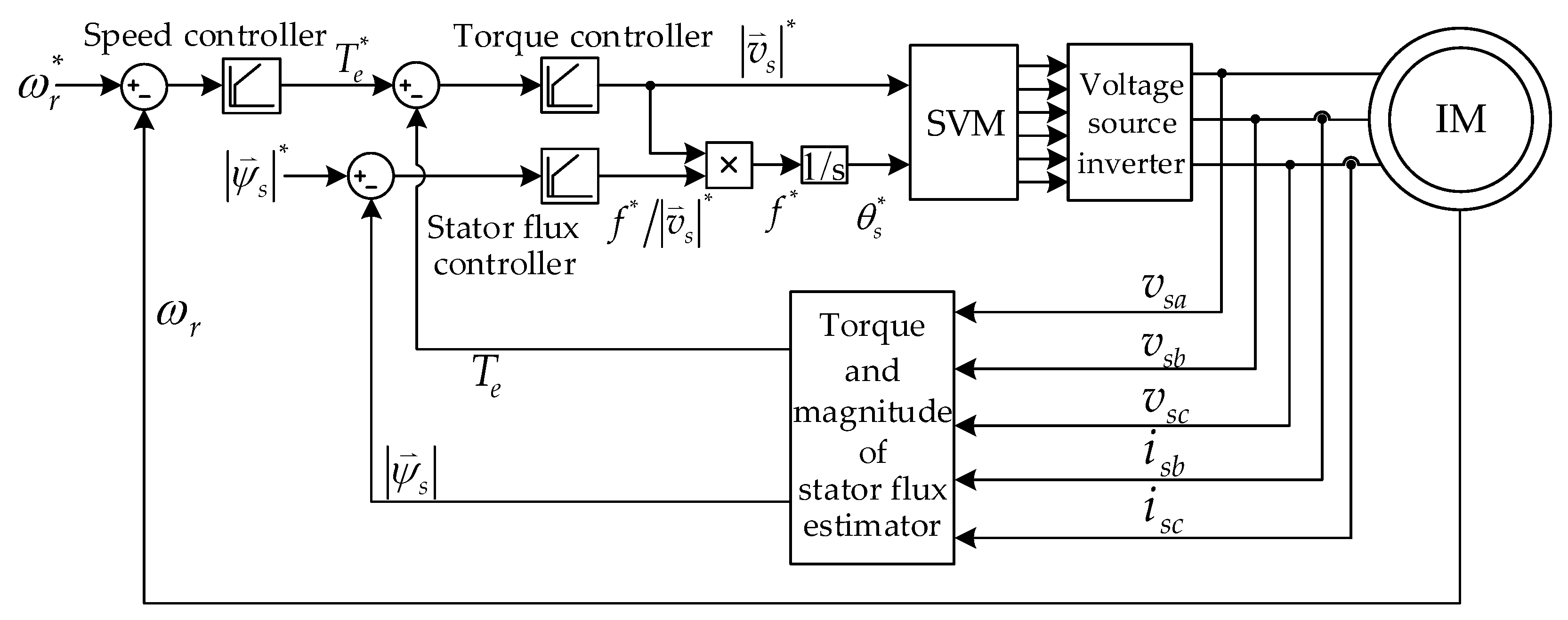
is a constant. In accordance with these concepts, the block diagram of DTC-CVFC for three-phase IM drives is shown in
Figure 1.
In
Figure 1,
is the mechanical speed;
is the stator phase angle; “*” stands for the reference value; and
,
,
,
and
are the phase a, phase b and phase c stator voltage and stator current, respectively. PI controllers and SVM technique are utilized instead of the hysteresis comparators and look-up switching table of the conventional DTC. Furthermore, the coordinate transformation and current regulators are not used. The field-weakening operation is not considered in this paper. Hence, the stator flux magnitude reference is set as constant value. The torque and stator flux magnitude are calculated using Equations (5)–(8) [
38].
where
,
,
,
,
and
are d- and q- axis stator voltage components, stator current components and stator flux components, respectively. All quantities are expressed in stationary reference frame.
3. Online Artificial Neural Network Speed Estimator
The IM mathematical model in stationary reference frame under the assumption that magnetic circuit is linear, core losses are neglected, and magneto motive force (MMF) has sinusoidal distribution, is expressed as [
38]:
where
and
are d- and q- axis rotor current components, respectively,
is the electrical speed,
,
and
are the mutual, stator and rotor inductances, respectively, and
is the differential operator
.
To derive the estimated stator current consistent with DTC-CVFC technique, in which the stator flux is controlled variable, the stator flux equations that depend on stator and rotor currents are adopted as follows:
By substituting Equations (10) and (11) into Equation (9), the estimated stator current equation can be written as:
where
,
and “^” denotes the estimated value. Applying forward rectangular rule [
39] to Equation (12) and rearranging the result equation in accordance with ANN form that a weight of ANN must contain the speed, the discrete time estimated stator current is depicted in Equation (13):
From Equation (13), the estimated stator current can be written in ANN form as:
where
,
,
,
,
,
,
,
,
,
,
,
and
is the sampling period.
From Equation (14), ANN consists of two layers, input layer and output layer. Consequently, the suitable learning method for this ANN structure is Widrow–Hoff learning rule. Moreover, the weight update equation of this learning method is very simple so that Widrow–Hoff learning rule is more appropriate than other learning methods for online speed estimation [
36]. Therefore, a weight,
, in Equation (14) that contains the speed will be adjusted online by Widrow–Hoff learning rule to minimize the sum of squared errors between the measured stator current and the estimated stator current. The sum of squared errors at sampling
is defined by the energy function as:
where
.
To minimize the sum of squared error, Widrow–Hoff learning rule is used to adjust weight
as:
The updated weight can be written as:
By substituting Equation (16) and
into Equation (17) and rearranging, the estimated speed can be written as:
where
is the positive value called as the learning rate,
means transpose and
.
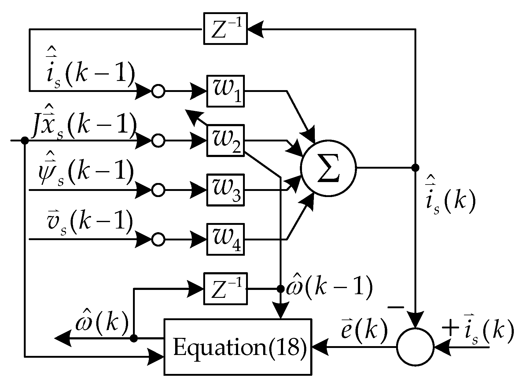
The block diagram of the proposed online ANN speed estimator is represented in
Figure 2.
In
Figure 2,
,
,
and
.
As shown in
Figure 2, only the weight
is adjusted online by Equation (18). Consequently, the convergence of the estimated stator current to the measured stator current strongly depends on the convergence of the estimated speed. The speed estimation in Equation (18) behaves as a low pass filter with the time constant that is inversely proportional with learning rate [
40]. Hence, the estimation system will be stable if the positive learning rate is adopted. The small value of learning rate leads to the slow rate of the convergence while the large learning rate value brings to the fast convergence. However, it may cause the fluctuations in the estimated speed. To assure the stability, the learning rate should be selected carefully.
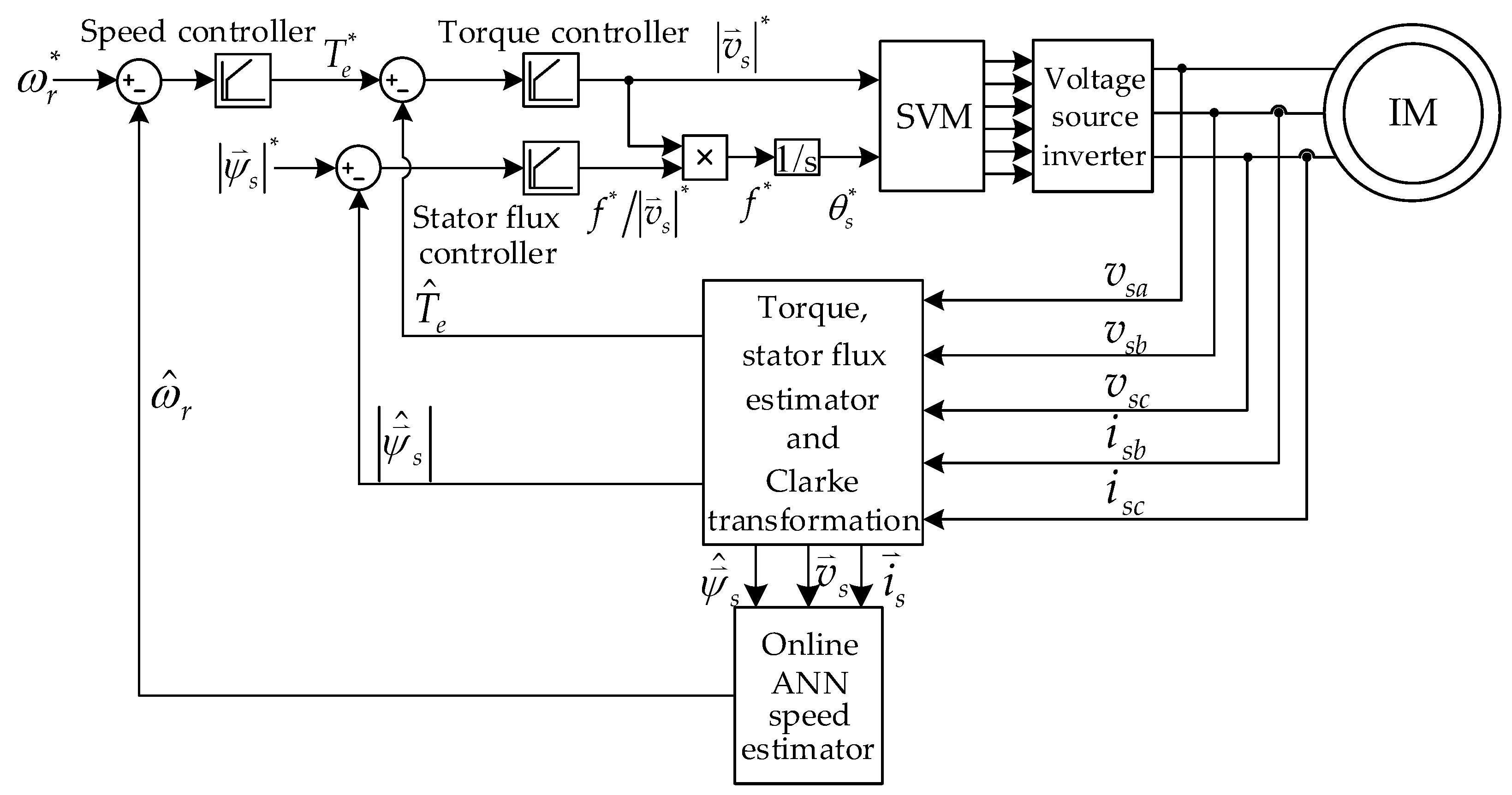
4. Simulation and Experimental Results
To validate the effectiveness, DTC-CVFC incorporated with the proposed online ANN speed estimator is simulated and experimented. The block diagram of the proposed speed sensorless control system is shown in
Figure 3. The simulation is performed in Matlab/Simulink environment. The rule of thumb [
41] is used to define the PI controller parameters for speed, stator flux magnitude and torque controllers. IM parameters and PI controller parameters are shown in
Table 1 and
Table 2, respectively. To estimate speed online in accordance with Equation (18), only two parameters must be known that is the initial estimated speed and the learning rate
. The initial estimated speed and the learning rate are set equal 0 and
, respectively. These parameters are used in the simulations and experiments. For experiment, to avoid using the pure integrator, the modified integrator with an amplitude limiter [
42] is adopted for the stator flux estimation because it is easy to implement, is suitable to the control method with constant flux magnitude control, does not require the speed information and can estimate the stator flux accurately in wide speed range. The cutoff frequency is 2 rad/s and limiter level is set equal to the stator flux magnitude reference that is 0.7 Wb for this stator flux estimator.
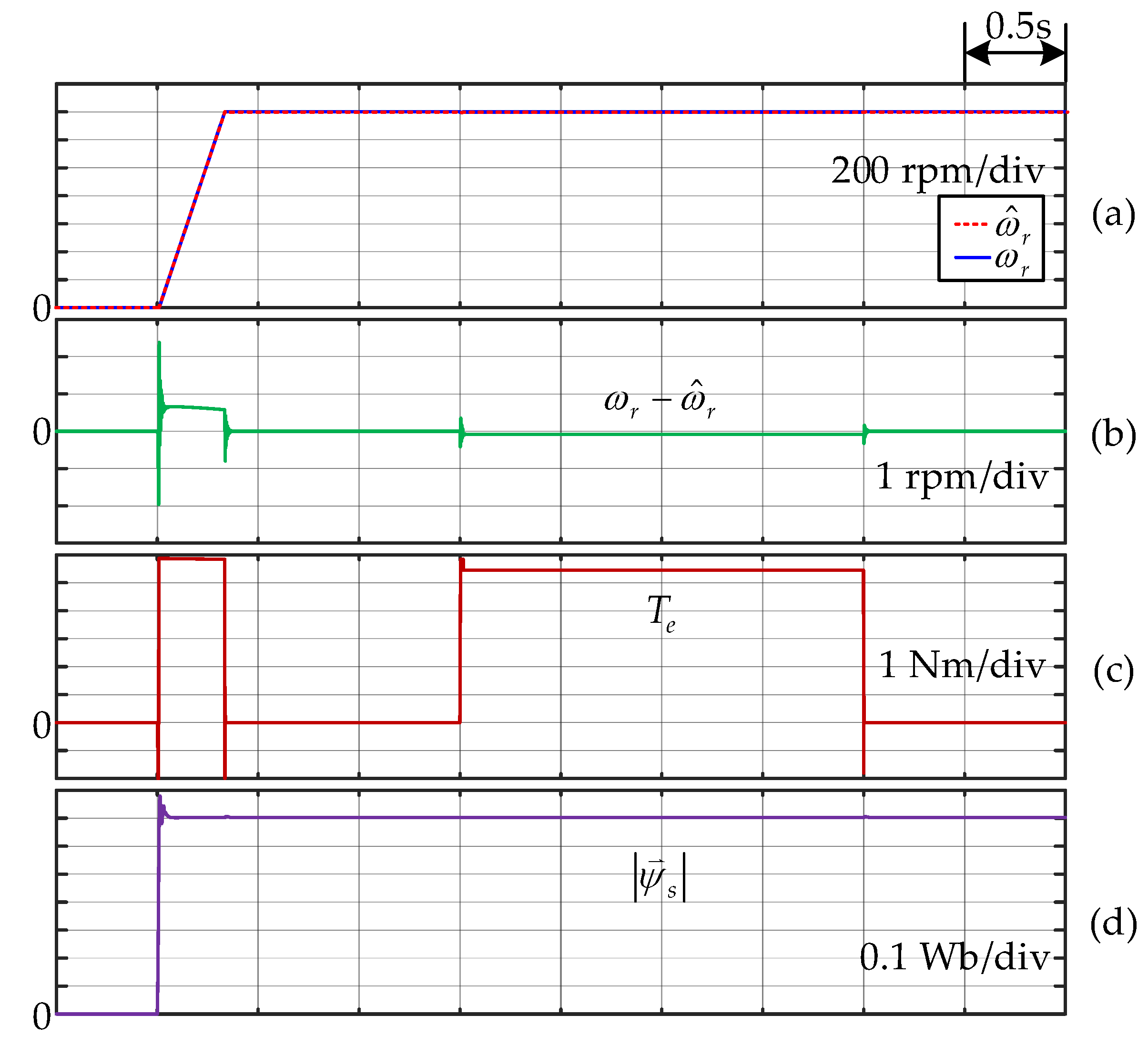
For simulation, the speed references are instantly changed from 0 rpm (standstill) to 1400 rpm (rated speed) for high speed operations and from standstill to 100 rpm for low speed operations both at time 0.5 s. The load torque is stepped from no load to full load (5.45 Nm) at time 2 s, then returns to no load again at time 4 s in each simulated situation.
The simulation results in high and low speed operations are shown in
Figure 4 and
Figure 5, respectively. The online ANN speed estimator can estimate the speed correctly in both high and low speed ranges, as seen from the difference between the actual speed and the estimated speed (
) in
Figure 4b and
Figure 5b for high speed and low speed, respectively. The maximum estimation error in high speed is around 2.5 rpm, with the same result for low speed. It can be concluded that the estimation errors are very small in transient operations and close to zero in steady-state operations. Speed, torque and stator flux magnitude are precisely controlled in steady-state conditions and has fast transient responses in both high- and low-speed regions, as shown in
Figure 4a,c,d and
Figure 5a,c,d, respectively.
The experimental setup is displayed in
Figure 6. A direct current (DC) generator with 1 kW, 220 V, 5.2 A and 2000 rpm connected to a resistor which is simulated as mechanical load for the tested motor. All algorithms for control, stator flux estimation and speed estimation are executed on DSP ADMC331. To ensure that it will have enough time for algorithm processing, data acquisition and conversion of analog to digital converter (ADC) and digital to analog converter (DAC), the sampling time is set equal 100 µs. The speed references are stepped from standstill to 1400 rpm and standstill to 100 rpm for high and low speed ranges testing, respectively. In each testing situation, the full load torque is applied when the speed response reaches the steady-state condition.
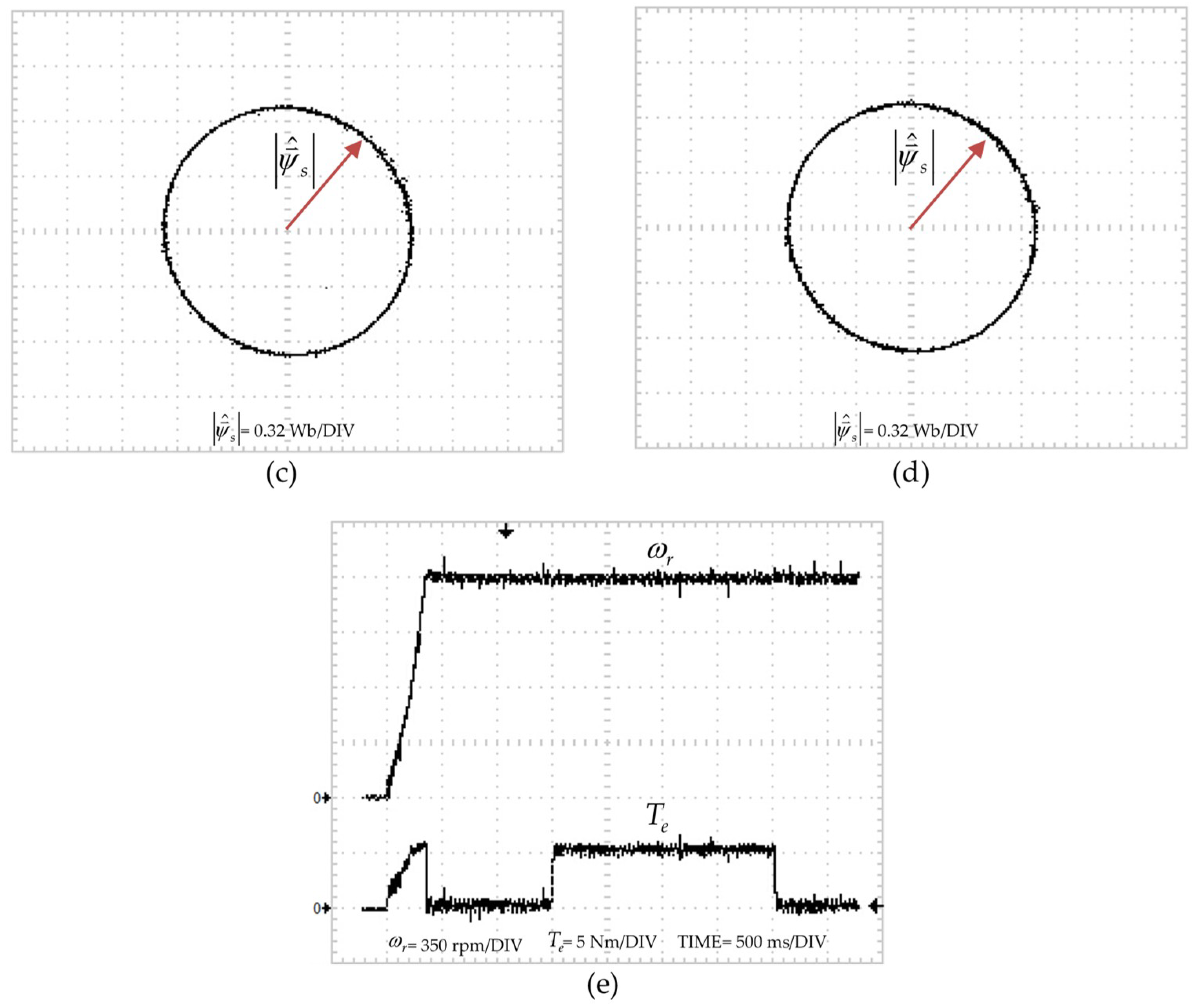
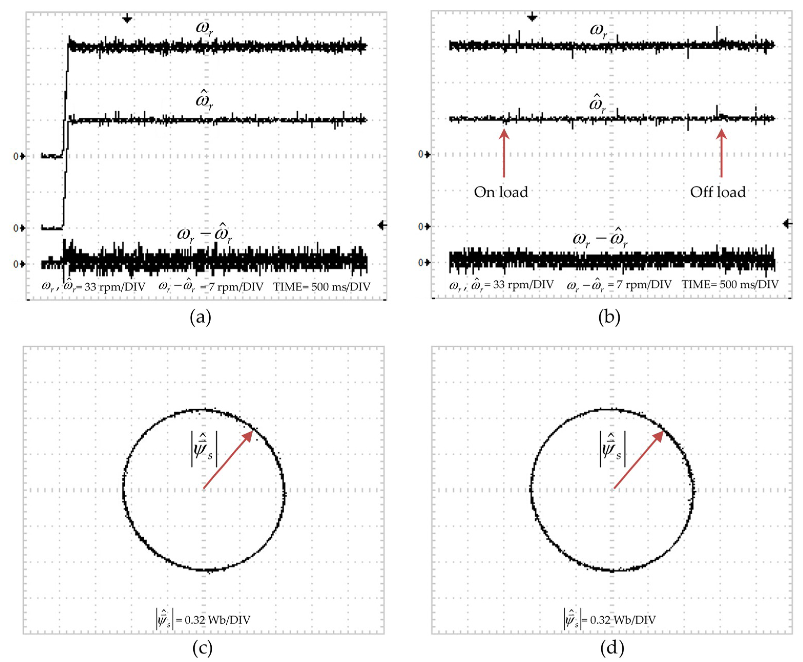
Figure 7 and
Figure 8 demonstrate the experimental results in high and low speed operations, respectively. The proposed online ANN speed estimator can estimate the speed accurately when motor starting and during taking load, as shown in
Figure 7a,b and
Figure 8a,b. The maximum estimation errors occur when motor starting with the value about 12 rpm for high speed and 5 rpm for low speed.
Figure 7c,d shows the stator flux trajectories when no load and full load of high speed operation. From these results, it is found that the controlled system is stable and the stator flux magnitude is controlled correctly. The same results can be observed in
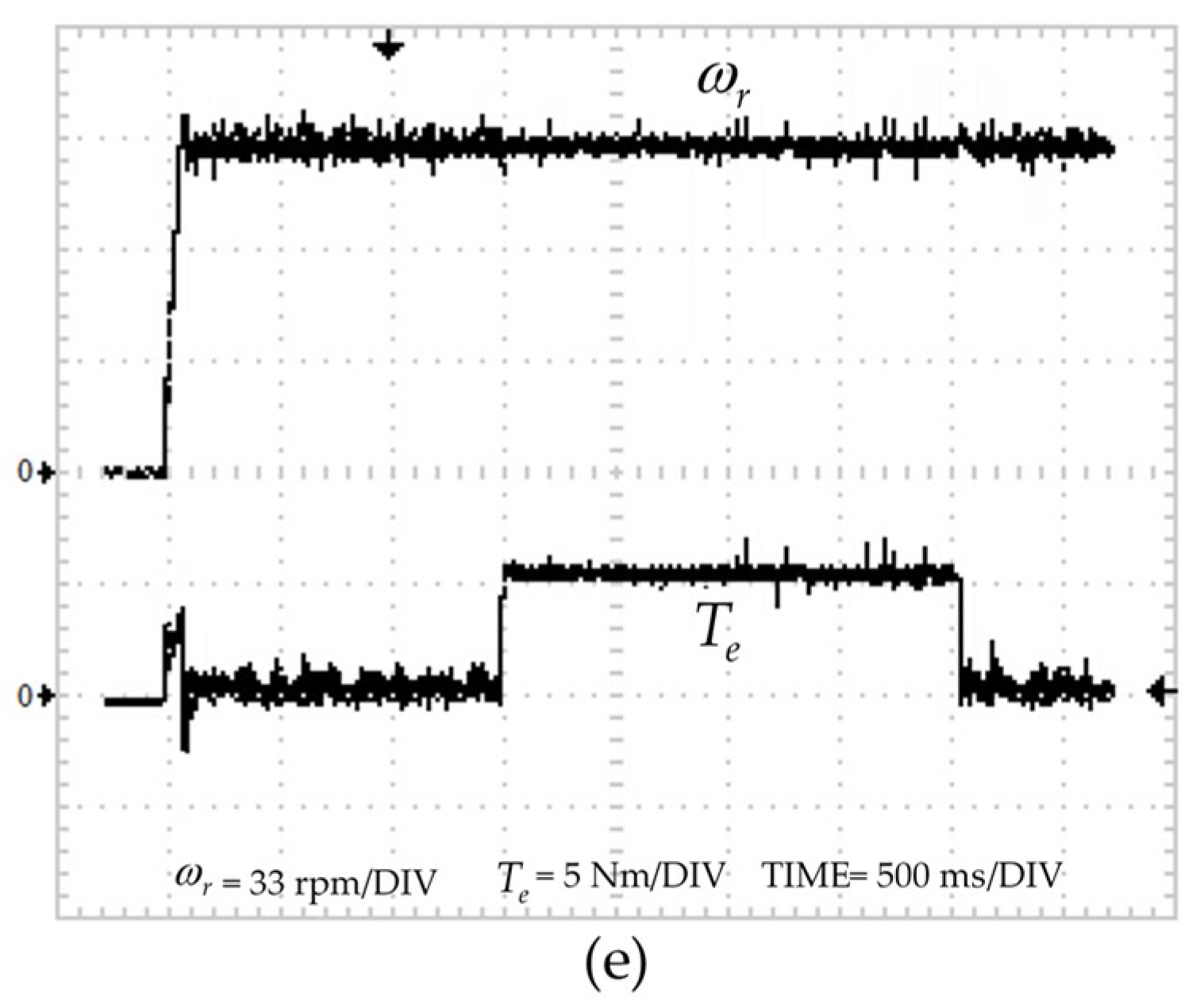
Figure 8c,d for the low speed operation. The torque responses are very fast in both high and low speed operations as clearly shown in
Figure 7e and
Figure 8e. The validity and effectiveness of the proposed speed sensorless control system are confirmed by these results.


