Energy and Exergy Analysis of Different Exhaust Waste Heat Recovery Systems for Natural Gas Engine Based on ORC
by
 , , and
Guillermo Valencia
1,* ,
,
Armando Fontalvo
2,
Yulineth Cárdenas
3,
Jorge Duarte
1 and
Cesar Isaza
4 1
Programa de Ingeniería Mecánica, Universidad del Atlántico, Carrera 30 Número 8-49, Puerto Colombia, Barranquilla 080007, Colombia
2
Research School of Electrical, Mechanical and Material Engineering, The Australian National University, ACT 2600, Australia
3
Departamento de Energía, Universidad de la Costa, Barranquilla 080002, Colombia
4
Programa de Ingeniería Mecánica, Universidad Pontificia Bolivariana, Medellín 050004, Colombia
*
Author to whom correspondence should be addressed.
Energies 2019, 12(12), 2378; https://doi.org/10.3390/en12122378
Submission received: 18 May 2019
/
Revised: 18 June 2019
/
Accepted: 18 June 2019
/
Published: 20 June 2019
(This article belongs to the Special Issue Organic Rankine Cycle for Energy Recovery System)
Abstract
:Waste heat recovery (WHR) from exhaust gases in natural gas engines improves the overall conversion efficiency. The organic Rankine cycle (ORC) has emerged as a promising technology to convert medium and low-grade waste heat into mechanical power and electricity. This paper presents the energy and exergy analyses of three ORC–WHR configurations that use a coupling thermal oil circuit. A simple ORC (SORC), an ORC with a recuperator (RORC), and an ORC with double-pressure (DORC) configuration are considered; cyclohexane, toluene, and acetone are simulated as ORC working fluids. Energy and exergy thermodynamic balances are employed to evaluate each configuration performance, while the available exhaust thermal energy variation under different engine loads is determined through an experimentally validated mathematical model. In addition, the effect of evaporating pressure on the net power output, thermal efficiency increase, specific fuel consumption, overall energy conversion efficiency, and exergy destruction is also investigated. The comparative analysis of natural gas engine performance indicators integrated with ORC configurations present evidence that RORC with toluene improves the operational performance by achieving a net power output of 146.25 kW, an overall conversion efficiency of 11.58%, an ORC thermal efficiency of 28.4%, and a specific fuel consumption reduction of 7.67% at a 1482 rpm engine speed, a 120.2 L/min natural gas flow, 1.784 lambda, and 1758.77 kW of mechanical engine power.
1. Introduction
The technological advances developed in organic Rankine cycles (ORC) applied to waste heat recovery (WHR) systems could become a promising feature for the engine manufacturing industry due to its capacity to reduce fuel consumption, increase net power output, and reduce greenhouse gas emissions [1].
ORC is considered as a feasible tool to increase overall conversion efficiency in industrial processes due to its capacity to recover energy from alternative sources, such as exhaust gases, cooling water, or lubricating oil, by using organic working fluids [2]. Furthermore, ORC configuration can be modified to maximize overall engine–ORC system performance by optimizing net power output, first law, and exergy efficiencies and minimizing exergy destruction [3]. Nevertheless, ORC–engine coupling must be carefully designed to avoid safety, performance, and revenue issues such as gas–fluid contact, as well as weight, complexity, and backpressure increase [4].
ORC–WHR research has addressed the integration between ORC and combustion engines. Plenty of studies have established that ORC improves the overall conversion efficiency by increasing net power production without penalizing fuel consumption. Patel and Doyle [5] presented a first attempt for WHR from diesel engines by using ORC. Their ORC system achieved an overall power increase of 13% in a Mack 676 diesel vehicle engine without increasing fuel consumption. Peris et al. [6] simulated six ORC configurations for WHR from cooling water in internal combustion engines (ICE) by using 10 non-flammable fluids. Their study showed that ICE electric efficiency could be increased by 4.9–5.3%, by achieving overall conversion efficiencies up to 7.15% at a relatively low-temperature cooling water (90 °C). Yu et al. [7] simulated a diesel engine–ORC integration for WHR from the engine exhaust gases and cooling system by using R245fa as the ORC working fluid. Their results showed that 75% of exhaust gases energy and 9.5% of cooling water energy could be recovered if ORC operating conditions are optimized and controlled to maintain the power output. However, these results are limited to an exergetic analysis of a single ORC configuration. Lu et al. [8] proposed an integrated diesel internal combustion engine and simple ORD (SORC) with solids adsorption technology for waste heat recovery from the cooling system and the engine exhaust gases. Their results showed a maximum recoverable power from the cooling process and exhaust systems of 67.9 kW and 82.7 kW, respectively.
Vaja and Gambarotta [9] evaluated the performance of SORC and ORC with a recuperator (RORC) configurations for WHR in a stationary 2.9-MW ICE at a single operation point. The results showed an increase of 12% in the overall efficiency of the system. Kalina [10] investigated the performance of a biomass power generation plant. The plant consisted of two natural gas ICE coupled to a biomass gasifier and an ORC. The ORC system was used as a WHR system to produce power from the engine’s exhaust line and cooling system. Mingshan et al. [11] analyzed a combined heavy-duty diesel engine–SORC system for WHR. This system achieved a heat recovery efficiency between 10–15% when the heat exchanger operation is optimized. This publication also evaluated the engine operation under partial load conditions with a medium–high power condition. They concluded that variations in engine rotational speed must be determined to evaluate the true performance of the combined system.
Regarding ORC and stationary compressed natural gas (CNG) engines integration, two approaches have been studied: the use of multiple temperature loops for WHR from the engine intercooler, cooling system, and exhaust gases, and the use of single-temperature loops for WHR from engine exhaust. Within the first approach, Yao et al. [12] were the first ones to propose an ORC system for WHR from the engine intercooler, exhaust gases, and cooling system by using a low and a high-temperature loop. Their ORC system used R245fa and achieved 10.8% thermal efficiency and 26.9 kW of power, which increased overall power production by 33.7%, keeping the same fuel consumption. Yang et al. [13] optimized Yao’s ORC configuration by using a genetic algorithm, but their reported performance was lower than Yao’s results: 8.8–10.2% thermal efficiency and 23.6-kW net power output. Yao’s configuration was studied again by Yang et al. [14] and analyzed the thermodynamic performance of the ORC with double-pressure configuration (DORC) operating with six working fluid groups integrated into a compressed natural gas engine, but performance indicators such as the waste heat recovery efficiency and specific fuel consumption were not considered. Wang et al. [15] also studied a dual-loop ORC system for WHR in stationary CNG engines but using R1233zd and R1234yf as working fluids and two recovery heat exchangers to increase ORC efficiency. The results showed that ORC efficiency was 10–14% when R1233zd was used in the high-temperature loop, and R1234yf was used in the low-temperature loop.
Within the second approach, Han et al. [16] carried out a dynamic simulation of an ORC with a double piston expander and R245ca as a working fluid. Their system took advantage of the engine exhaust gases to produce power in the ORC piston expander and compress the engine natural gas. However, they focused on the component efficiencies and compression benefits, but their study did not report overall efficiency values. Song et al. [17] proposed an RORC working with R416A as the ORC fluid. Their results showed that this approach increased the overall conversion efficiency by 6%. Liu et al. [18] examined the effect of engine load on the performance of an ORC cycle combined with a stationary motor and R245fa as the working fluid. Their results showed ORC efficiencies between 16.3–25.9% when the engine load varies between 40–100%, respectively.
The selection of ORC working fluid is a key design step because it defines the operation limits and the power production potential. However, publications have shown that working fluid selection depends on the heat source and temperature limits. Chacartegui et al. [19] studied a low-temperature SORC configuration in medium and large-scale combined cycle plants for WHR from commercial gas turbines. Their study considered R-113, R-245, isobutene, toluene, cyclohexane, and isopentane as working fluids. The results showed that toluene and cyclohexane achieved the highest combined cycle efficiency—up to 60%--which is high global efficiency in this process. Qiu et al. [20] examined the experimental integration of a small-scale thermoelectric generation with a dual ORC. Drescher and Brüggemann [21] performed a screening of suitable organic working fluids for biomass-fired applications. Their selection involved critical temperature and pressure, dryness, turbine and pump efficiencies, and autoignition temperature. However, they obtained a group of suitable fluids rather than an optimum working fluid. Mago et al. [22] studied the effect of working fluid selection on the ORC performance at different heat source temperatures, supporting Drescher and Brüggemann’s conclusions.
Kosmadakis et al. [23] tested more than 30 organic fluids and stated that R245fa is a suitable working fluid for ORC applications with ICE in terms of net power and thermal efficiency, but its use is restricted as international standards promotes low global warming potential (GWP) organic substances. Regarding solar thermal energy conversion, Tchance et al. [24] established that R134a is a suitable fluid due to its low toxicity and flammability, in addition to the high-pressure ratio and efficiency that can be achieved. Tian et al. [25] performed a energy analysis of a combined diesel ICE–SORC system to evaluate 20 different working fluids in terms of net output power and thermal efficiency. The study showed that R-141b showed the highest net power output (60 kJ/kg), but R-123 achieved the highest thermal efficiency (16.60%). Hung et al. [26] investigated an SORC integrated into a solar ventilation system. Their results showed an overall efficiency increase of 6.2%. Zare [27] evaluated the revenue of three ORC geothermal plants. They showed that the RORC configuration improves thermal efficiency, but requires additional components, increasing the total exergy destroyed, and affecting the overall exergy efficiency. This trend was confirmed by Fontalvo et al. [28], who evaluated three ORC configurations for low-temperature WHR and showed that SORC had the highest revenue because the additional equipment increases the exergy destruction of the system.
Exergy analysis is an important tool to identify key design aspects that may improve overall conversion efficiency and maximize resource utilization. ORC research has shown that exergy analysis can be used to provide guidelines in ORC design for a wide range of heat sources. In addition, the calculation of exergoeconomic costs aims to set an economic value for materials and energy flows, providing a reasonable base for the allocation of economic resources [29]. Kerme and Orfi [30] evaluated the effect of the turbine inlet temperature on the exergy efficiency of an ORC driven by solar collectors. As a result, they showed that an increase in turbine inlet temperature increases exergy efficiency and reduces exergy destruction. The conservation of natural resources, the limited availability of spaces to generate energy through some renewable sources, cost savings, policies, and the national regulatory framework are some of the most important factors that encourage the research of a more efficient energy generation process for internal combustion engines [31].
The main contribution of this paper is to present the comparative analysis results of some energetic and exergetic performance indicators of a 2-MW natural gas engine integrated with waste heat recovery systems based on SORC, RORC, and DORC configurations with different organic working fluids such as toluene, cyclohexane, and acetone. The maximum net output power of the bottoming ORC cycle was studied for differents engine load percentages, which implied studying the exhaust gas thermodynamic properties and engine thermal performance in detail. Also, parametric studies are developed to identify the influence of evaporation pressure on exergy destruction for each component, and performance indicator. These result help obtain the best ORC operational condition and configuration in terms of rational use of energy and environment preservation by increasing the overall energy and exergy efficiency of the Jenbacher JMS 612 GS-N. L natural gas engine of 2 MW with the bottoming ORC cycle.
2. Methodology
2.1. Description of the System
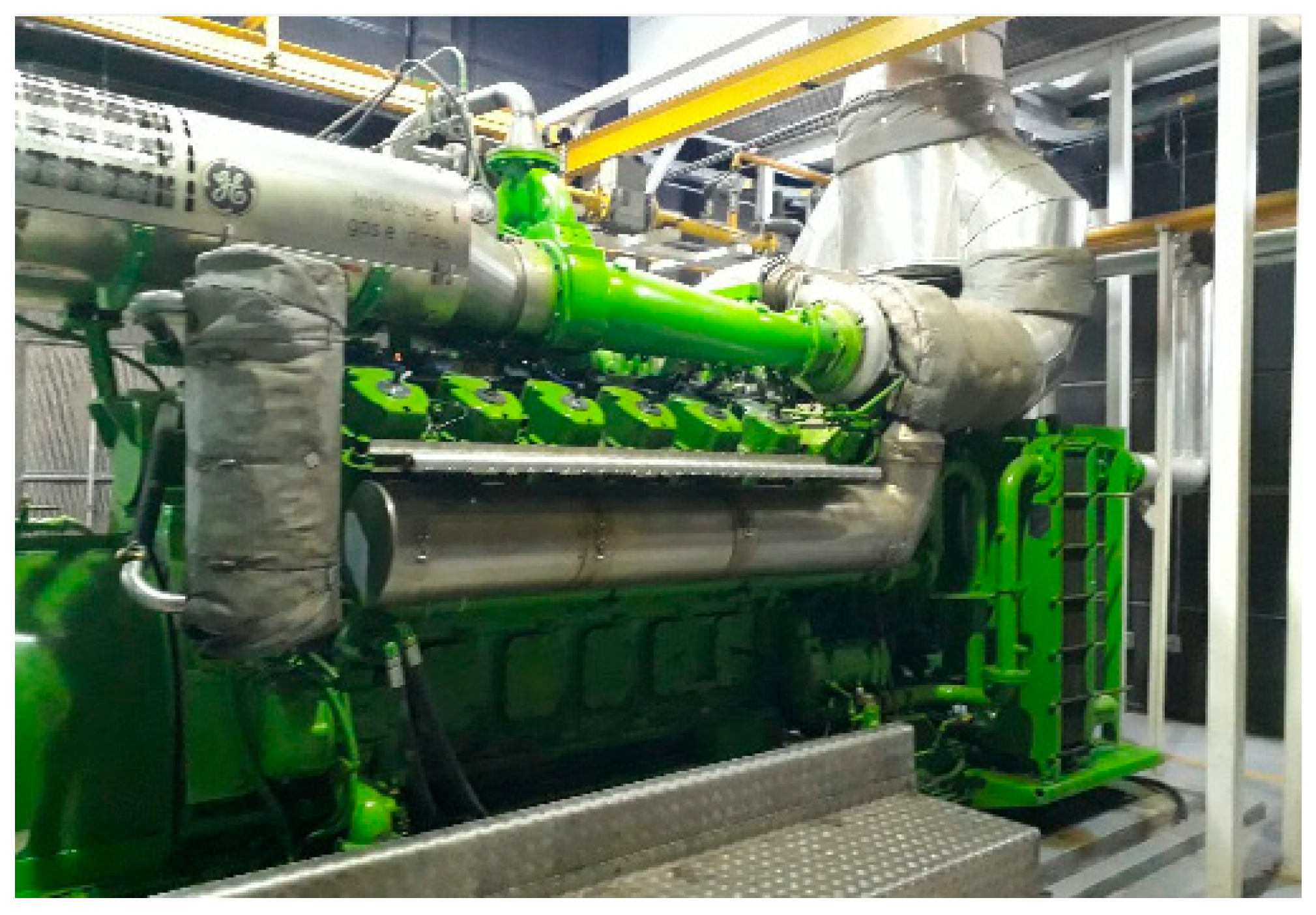
This section presents a general description of the 2-MW natural gas engine and each ORC configuration and operation. In this study, a Jenbacher JMS 612 GS-N. L engine (Figure 1) is considered to evaluate the ORC–WHR systems. The main design and operation engine parameters are summarized in Table 1. Fuel composition and air–fuel mixture supply conditions for the studied plastic production plant are presented in Table 2. The air–fuel mixture conditions are set to obtain an optimum flammable gas–air mixture and an exhaust gas temperature of 420–460 °C after the turbocharger expander.
2.2. Description of the SORC, RORC, and DORC
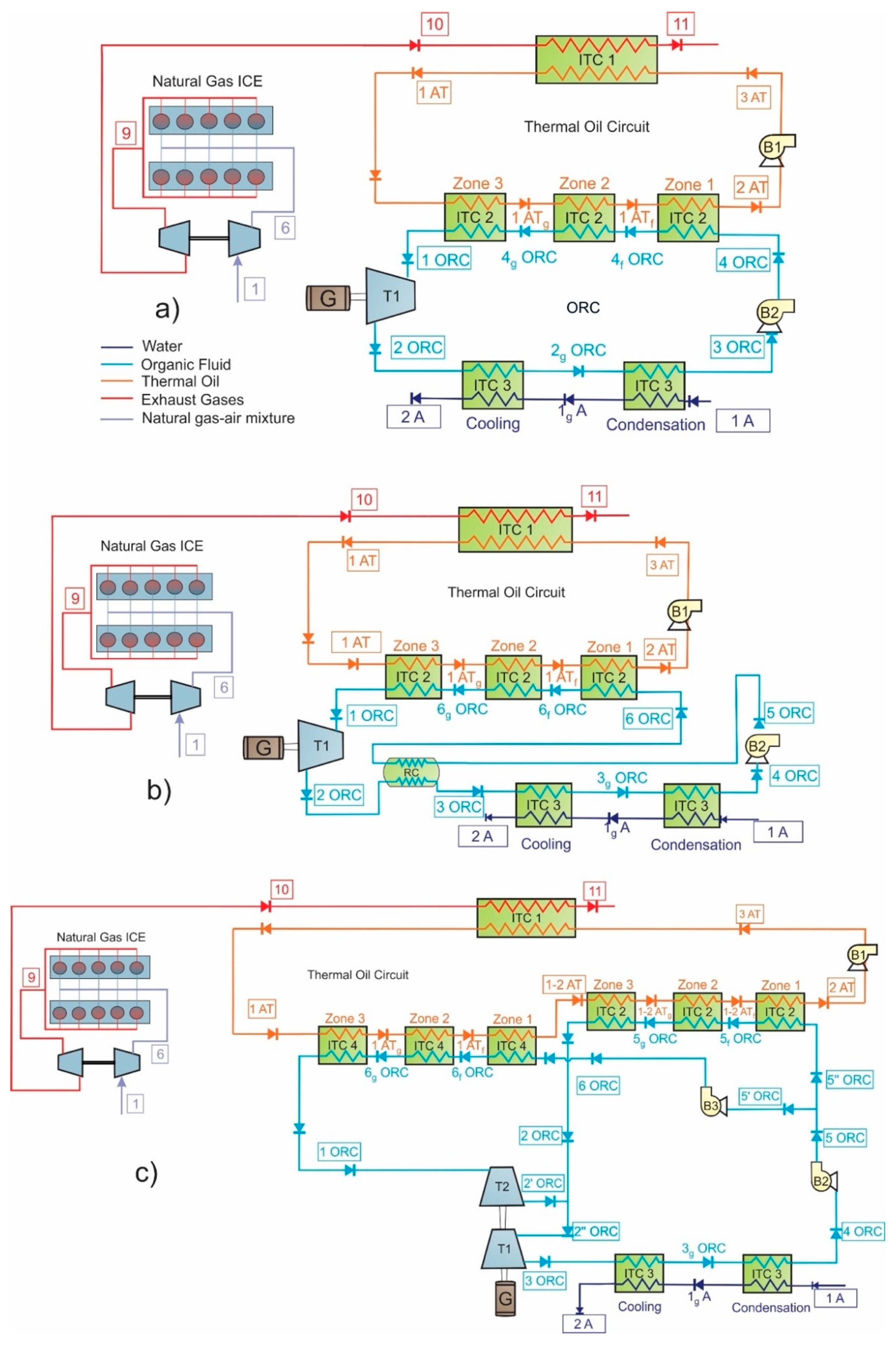
The studied ORC configurations are presented in Figure 2 and are based on the previous work of Fontalvo et al. [28]. The SORC physical structure is shown in Figure 2a. SORC operation is as follows: an air–fuel mixture (stream 1) is compressed to mixing conditions (stream 6) and supplied to the combustion chamber. The exhaust gases at the manifold outlet (stream 9) are expanded at the turbocharger expansion stage (stream 10) before they transfer heat to the thermal oil circuit at the shell and tube heat exchanger (ITC 1), and they are finally sent to the atmosphere (stream 11). In the thermal oil circuit, the oil that receives heat from the exhaust gasses (stream 1 AT) is used to preheat (zone 1), evaporate (zone 2), and superheat (zone 3) the ORC working fluid in the evaporation unit (ITC 2) before it is pumped (streams 3AT) and sent to the shell and tube heat exchanger (ITC 1). In the SORC, the high-pressure organic working fluid (1 ORC) is expanded at the ORC turbine (T 1) to the SORC lowest pressure (2 ORC) before it is cooled down and condensed (ITC 3). Then, the fluid is pumped to the ORC highest pressure (4 ORC) and sent back to the preheating, evaporating, and superheating zones to complete the cycle.
The ORC configuration with internal heat recovery (RORC) is shown in Figure 2b. This configuration is based on the SORC presented above, but an internal recovery unit (RC) is included in the ORC system to improve conversion efficiency by using the turbine outlet stream (2 ORC stream) to preheat the fluid in the pump outlet stream (5 ORC) before it enters the preheating zone in the evaporation heat exchanger (ITC 2).
The DORC configuration is shown in Figure 2c. This configuration uses two evaporating pressures and requires two evaporation units (ITC 2, ITC 4), two pumps (B 2, B 3), two turbines (T 1, T 2), and one condenser (ITC 3). In the DORC configuration, the thermal oil that leaves the pump (stream 3 AT) is heated by the exhaust gases (stream 10) in the shell and tube heat exchanger (ITC 1) before it is sent to the high-pressure evaporation unit (ITC 4) where the thermal oil (stream 1 AT) is used to preheat, evaporate, and superheat the high-pressure ORC working fluid (stream 6 ORC). Then, the thermal oil leaving the high-pressure evaporation unit (stream 1-2 AT) is used to preheat, evaporate, and superheat the mid-pressure ORC fluid (stream 5” ORC) in the mid-pressure evaporation unit (ITC 2). In the ORC system, the high-pressure working fluid (stream 6 ORC) enters the first turbine stage (T 2), where it is expanded to the system middle pressure and mixed with the fluid (stream 2 ORC), leaving the mid-pressure evaporation unit. The mixed fluid (stream 2” ORC) enters the second turbine stage (T 1) where it is expanded to the system lowest pressure (stream 3 ORC) before it is cooled down and condensed (ITC 3). Then, the fluid is pumped to the ORC middle pressure (5 ORC) before it is split (streams 5’ ORC and 5” ORC). Stream 5’ is pumped to the system highest pressure and sent back to the high evaporation unit, while stream 5” is sent to the mid-pressure evaporation unit to complete the cycle. According to the literature, the DORC configuration increases the efficiency of the cycle by decreasing the thermal load dissipated to the environment [32].
3. Thermodynamic Modeling
Energy and exergy analyses are conducted for the ORC–WHR configurations by applying the first and second law of thermodynamics to each component in the configurations. In addition, a definition of Fuel-Product is presented for each configuration component, as well as first and second law performance metrics.
3.1. Energy Analysis
Every single ORC–WHR system component is considered as a control volume. Mass and energy balances are applied to each component according to Equations (1) and (2), respectively.
where is the mass flow rate, is the fluid specific enthalpy, and . and are the heat flow rate output and power inputs, respectively. Steady-state operation is assumed for each ORC component.
3.2. Exergy Analysis
The specific exergy is calculated by neglecting the variation of kinetic and potential energy, and it is calculated according to Equation (3):
where and are the reference state enthalpy and entropy, respectively, which are calculated at the reference conditions of and . The chemical exergy of the exhaust gases (stream 10) is calculated according to Equation (4) by considering a mixture of gases from the fuel combustion.
where is the molar fraction and is the exergy per mol unit for each gas.
ex = (h − h0) − T0(s − s0)
The exergy balance is applied to each ORC–WHR system component by means of Equation (5) [33]:
where is the fluid incoming exergy flow, is the fluid outcoming exergy flow, and is the exergy destruction.
Three performance metrics are used for the ORC–WHR systems: cycle thermal efficiency , heat recovery efficiency , and overall energy conversion efficiency [34]. Cycle thermal efficiency is calculated by means of Equation (6), while heat recovery efficiency is calculated using Equation (7), and overall energy conversion efficiency is calculated as shown in Equation (8).
Similarly, the absolute increase in thermal efficiency is calculated using Equation (9), which relates the ORC net power output and fuel energy. This indicator determines the improvement in the ICE performance by using a WHR–ORC recovery system.
Due to the ORC power output, there is a lower brake-specific fuel consumption (BSFC), which is calculated by Equation (10) [15]. The absolute decrease in specific fuel consumption is determined by Equation (11), which represents the reduction in fuel consumption at any particular operating conditions of the power generation engine:
The exergy efficiency based on the second law of thermodynamics . is calculated as shown in Equation (12):
where is the exergy supplied to the system and is the exergy recovered by the system. Exergy efficiency can be expressed as a function of the destroyed exergy by means of Equation (13):
Simulating each WHR–ORC configuration, the following assumptions were considered:
- Pressure drops in pipelines are neglected.
- Pressure drops in heat exchangers are calculated as a function of the equipment geometry and the hydraulic flow characteristics.
- All the WHR–ORC components of the cycle are thermally insulated.
- The thermal oil circuit absorbs temperature variations in exhaust gases to obtain steady-state operation in each ORC configuration.
A simulation program with the energy and exergy analyses was written in MATLAB R2018b® [35], and the thermodynamic properties were calculated by using REFPROP 9.0® [36]. The detailed equations of energy balances applied to each configuration are shown in Appendix A, Table A1.
A specific engine operating condition is selected (see Table 3) to make it possible to compare each of the simulation results for each configuration. Values in Table 3 are also selected because it represents the system operation in off-grid mode. The engine performance indicators for the selected base conditions are shown in Table 4, which are expected to be evaluated with each configuration. The design parameters considered for the WHR–ORC simulations are shown in Table 5. In addition, the input–output structure for the components of the proposed WHR–ORC systems is shown as in Table 6, as the exergy losses must be differentiated from the exergy destroyed in each configuration [37].
3.3. Validation
The SORC simulation model is validated by conducting a comparative analysis using previously reported results from Vaja and Gambarotta [9] and Tian et al. [25]. The main parameters considered in both references are shown in Table 7. Two working fluids are considered: R-11 and R-134a, and ORC thermal efficiencies are determined as a function of the turbine inlet pressure.
The validation results in Figure 3 evidence that the SORC model is accurate enough when it is compared to previous results from references [9] and [25]. When results are compared to Vaja and Gambarotta [9], the error is below 3% for R-11, below 6% for R-134a when the turbine inlet pressure is up to 1 MPa, and less than 3% when the turbine inlet pressure is above 2 MPa for R-134a. The pressure range in this study is set as 2.5–3 MPa; therefore, it can be observed that the relative error in Figure 3 is below 1% compared to that of Huan Tian et al. [25], which guarantees the accuracy of the results.
For RORC model validation, the results of this system for a geothermal application were taken from Emam et al. [39] and Zare et al. [27]. The parameters considered for both investigations are shown in Table 7. The following considerations were assumed to perform the comparative analysis of the RORC:
- The processes and subsystems are assumed to be in steady state.
- All devices were considered in adiabatic conditions.
- Pressure drops in ORC devices and pipelines are neglected.
- The reference temperature for exergy calculations is 288 K.
Validation results for RORC are shown as in Table 8. A good agreement can be seen between this study and the previously published ORC performances from Emam et al. [39] and Zare et al. [27]. For isobutane, error ranges between 0.62–0.73% for thermal efficiency. On the other hand, exergy efficiency relative error is between 0.18–0.35%.
4. Results and Discussions
From the simulation results obtained, it is possible to determine and calculate the stream and fluid properties for the proposed SORC, RORC, and DORC configurations. Detailed simulation results are shown in Appendix B, Table A2 for the case of SORC. A summary of the main results obtained for the engine WHR system is shown in Table 9.
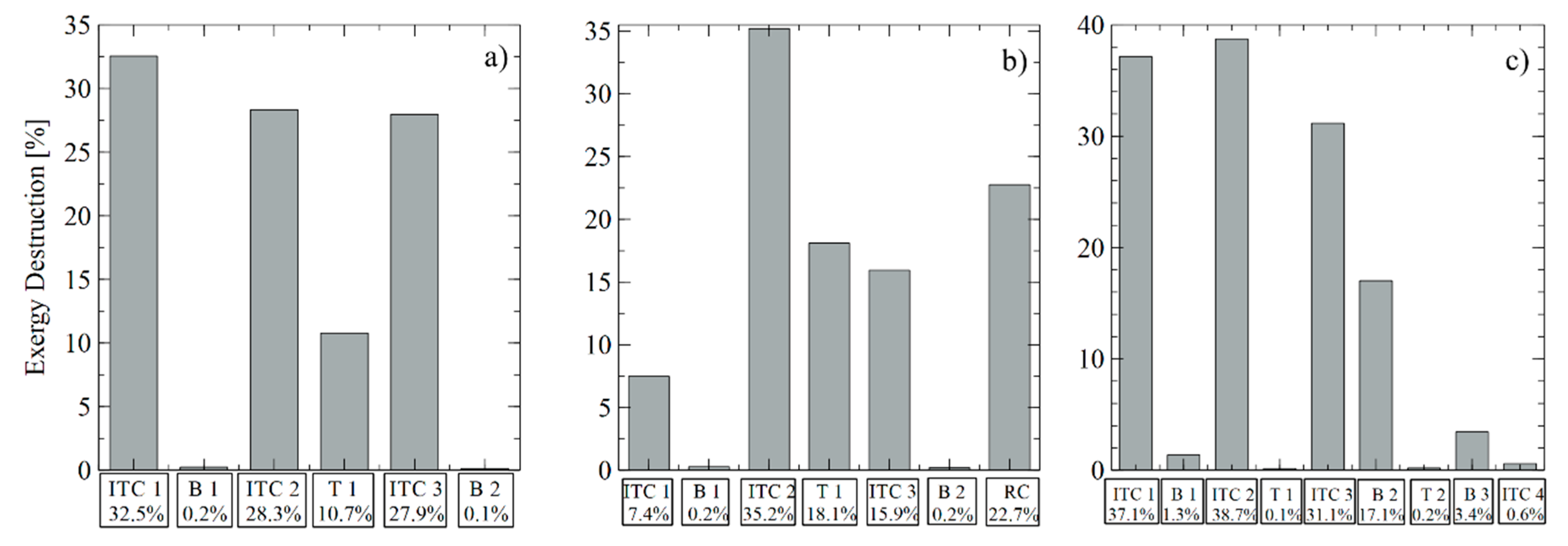
Results from the exergy analysis are presented in Table 10. Results in this table are calculated through the input–output definition in every component of the SORC configuration. The exergy destruction fraction in each component of the cycle is calculated from the results of the input–output definition and the exergy destruction percentages are presented in Figure 4a.
It is observed that the shell and tube heat exchanger (ITC 1) has the highest exergy destruction by achieving 32.5% of the cycle’s exergy destruction, followed by the evaporation unit (ITC 2) with 28.3%, and the condenser (ITC 3) with 27.9%. On the other hand, pumps show the lowest exergy destruction contribution. Due to operational restrictions on the turbine inlet organic fluid temperature, it is not possible to reduce the evaporation unit minimum temperature to obtain less generation of entropy and less exergy destruction in this equipment. Nevertheless, these temperature differences in heat exchangers can be optimized for better performance.
The use of isentropic or dry fluids in the RORC configuration allows obtaining superheated and relatively high-temperature conditions at the turbine outlet (2 ORC stream) [40]. This is the case of organic fluid toluene in RORC, as shown in Appendix B, Table A3. Therefore, the recovery heat exchanger (RC) uses this energy at the turbine outlet to preheat the stream leaving the pump (6 ORC stream) [41]. This preheating strategy [42] increases the thermal efficiency by 2.6%, while in SORC, the increase is 1.8%. Thus, the whole engine–WHR–RORC configuration shows a specific fuel consumption of 166.21 g/kWh, which is 2% less than the engine–WHR–SORC specific fuel consumption as shown in Table 10 by using the same fluid and operation conditions.
It can be seen that the ORC performance increases when the recovery heat exchanger (RC) is included, as it increases the turbine power output for the same heat input from the exhaust gases. The efficiency improvement is strongly related to fluid properties, especially to specific heat [43]. The results confirm that the recovery system does not affect the turbine power output or pump power consumption, but it modifies heat transfer in both the evaporation unit and the condenser [44], which have the highest exergy destruction, as shown in Table 11.
The exergy destruction contribution in each cycle component is presented in Figure 4b. From this figure, it can be seen that the exergy destruction is 33.82 kW (35.2%) in the evaporator, followed by the recuperator with 21.86 kW (22.8%). Also, it can be seen that pump contribution to exergy destruction is only 0.5%.
For the DORC configuration, there are two different evaporating pressures; however, the 2 ORC, 2’ ORC, and 2” ORC streams are mixed at the same pressure, and then enter the turbine (T1). In addition, at the low-pressure pump outlet (B2), the states 5 ORC, 5’ ORC, and 5” ORC have similar thermodynamic properties with different mass flow rates, as shown in Appendix B, in Table A4.
Table 9 presents the performance metrics of engine–WHR–DORC. It can be observed that this configuration only achieves an overall energy conversion efficiency of 6.68% and an overall exergy efficiency of 34.37% at the test conditions. According to Guzovi [45], these results are strongly related to the selected pressure ratio values, and this configuration presents better exergy efficiency and generates more power output than the SORC and the RORC configurations. In this configuration, the high-pressure evaporator (ITC 4) along with the shell and tube heat exchanger (ITC1) show the highest exergy destruction, as shown in Table 12, which can be explained by the temperature differences between the thermal oil and the organic fluid.
The component exergy destruction contribution to the WHR–DORC system is shown in Figure 4c. From this figure, the evaporators and condensers’ contribution is 86.4% of the total exergy destruction. As the organic fluid is evaporated in the heat exchangers, a closer match can be maintained between the thermal oil cooling temperature profile and the ORC working fluid temperature profile, which reduces exergy losses.
4.1. Sensitivity Analysis
4.1.1. Effect of Evaporation Pressure
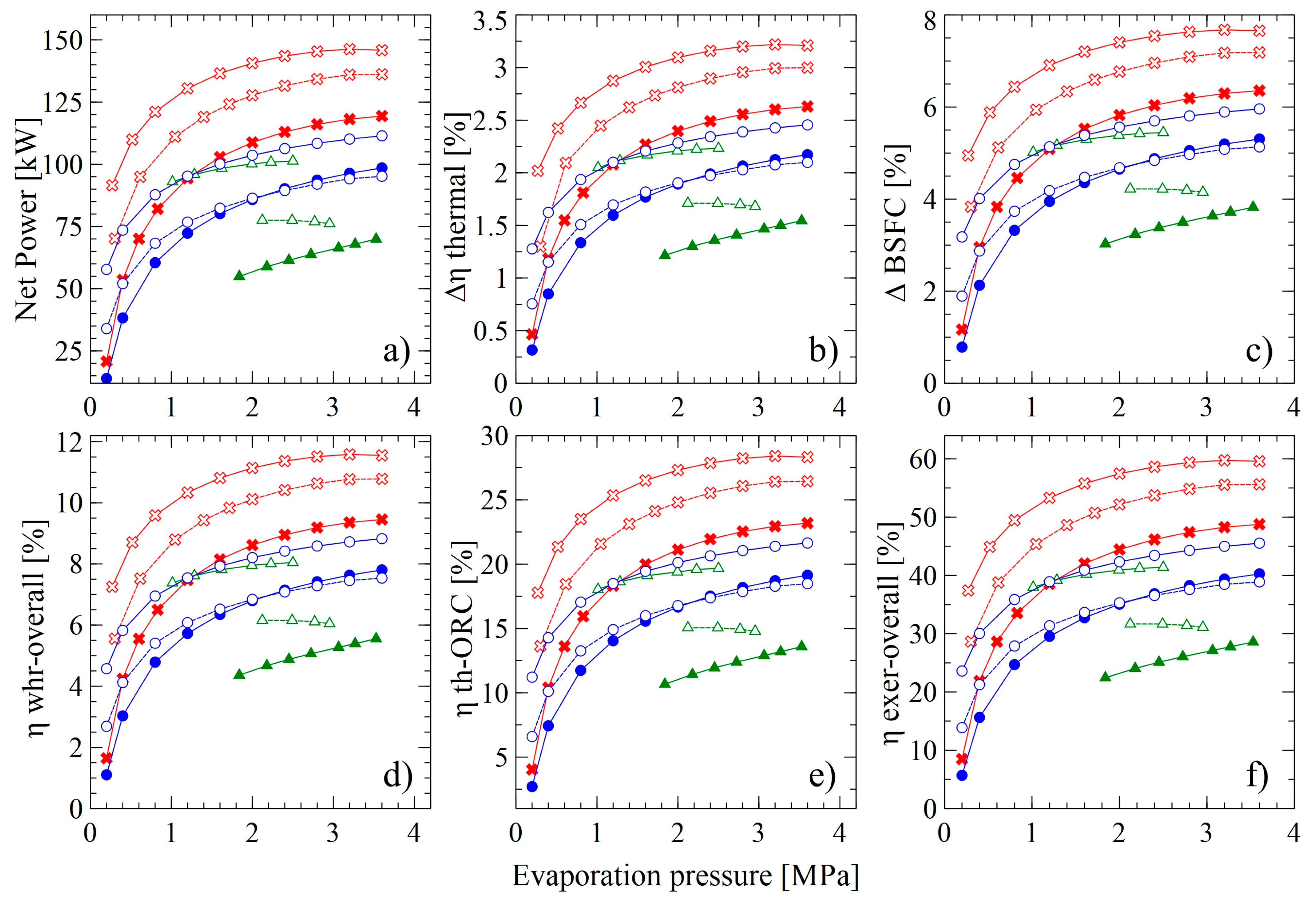
Considering the relevance of the evaporation pressure on the operation of these systems, a comparative analysis of the net power, an absolute increase of thermal efficiency, and absolute decrease of the specific fuel consumption is presented in Figure 5 for each engine–WHR–ORC configuration. For the DORC, high evaporation pressure is reached by changing the pressure ratio at the B3 pump, while the pressure ratio at the B2 pump is kept fixed at three for toluene, 10 for acetone, and 1.5 for cyclohexane.
It is observed that the net power output is strongly related to the evaporation pressure, achieving the most profitable results for the toluene–RORC at an evaporation pressure of 3.4 MPa: 146.25 kW of net power, which is up to 31.9% more power than the toluene–SORC net power at the same evaporation pressure. It is not possible to achieve the same evaporating pressure in the DORC by changing the B3 pump pressure ratio, because the fluid temperature would be so high that the heat transfer in the evaporation unit will be reversed.
When comparing the absolute increase in thermal efficiency for the three ORC configurations, Figure 5b shows that the evaporating pressure increases thermal efficiency up to an upper limit [46,47]. For toluene at 3.4 MPa, the SORC increases engine efficiency by 2.44%, while the RORC increases it by 3.22%. Working fluids such as acetone and cyclohexane in the SORC achieve an absolute thermal efficiency increase of 2.15% and 2.09%, respectively. Therefore, toluene stands out as the working fluid that presents the best results performance. Furthermore, as the main objective of this research is to increase the overall conversion efficiency by generating additional power, a RORC is the best option, regardless of the working fluid. This is supported by Figure 5, where the highest specific fuel consumption reduction is 5.92% for the toluene–SORC combination and 7.67% for the toluene–RORC combination, while the lowest specific fuel consumption reduction is achieved by the acetone–SORC cycle, which is 0.78% at 0.2 MPa. However, it is important to mention that as the heat in the evaporator increases, the size of the evaporation unit in the RORC will increase the purchase equipment cost and reduce the revenue of the system.
By evaluating the overall energy conversion efficiency, as shown in Figure 5d, the toluene–SORC and the cyclohexane–SORC combinations achieve 8.78% and 7.54%, respectively, with 3.4 MPa. For the RORC configuration, acetone achieved the lowest efficiency (4.91%), which confirms that toluene is the potential fluid to be used in SORC and RORC.
The results also show that the toluene–RORC combination increases thermal efficiency from 21.53% to 28.41%, and increases global exergy efficiency from 45.29% to 59.76%, which confirms that toluene stands out among the studied fluids, at relatively low pressures.
The maximum net power output in the toluene–SORC combination represents 8.31% of the stationary motor-generating capacity at nominal speed. In addition, it is observed that toluene–SORC working at evaporation pressures between 2–3 MPa increases the net power output by 5.49% and up to 109.3 kW. The absolute increase in thermal efficiency goes up to 5.26%. Finally, the specific fuel consumption reduction increases by 5.21%. On the other hand, the increases for these variables in the RORC are 3.76%, 3.75%, and 3.47%, which allows us to conclude that toluene–SORC is the combination that stands out when considering this variable.
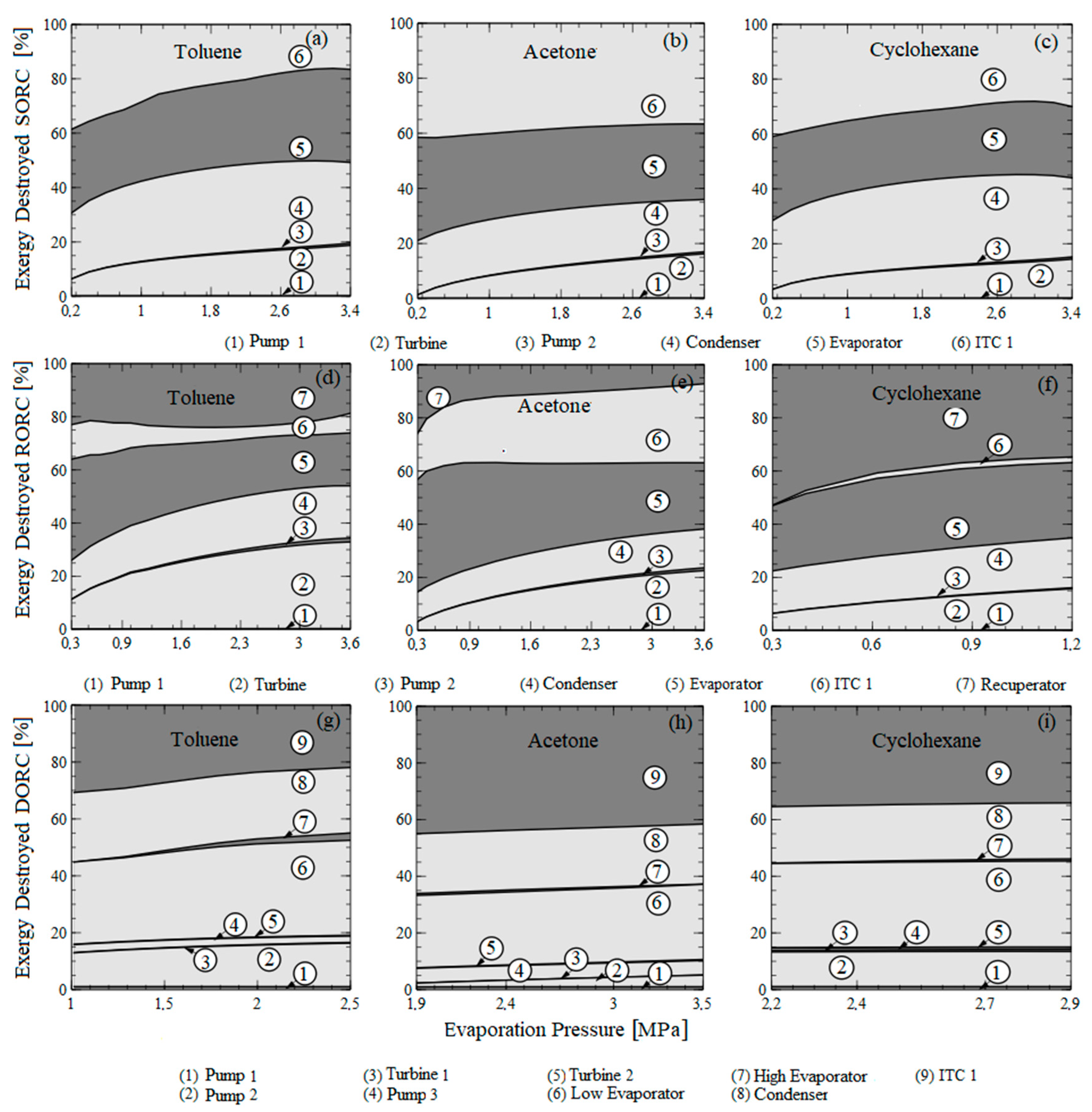
4.1.2. Analysis of the Influence of Evaporation Pressure on the Destruction of Exergy Configurations
To perform a comparative analysis of the exergetic performance for each ORC configuration, the fractions of exergy destruction in each component of the cycle were calculated with the three proposed working fluids. The exergy destruction fractions for each ORC configuration are shown in Figure 6, at different evaporating pressures for acetone, cyclohexane, and toluene.
The results demonstrate that the exergy fractions for the DORC cycle are higher than those for the SORC cycle, while the RORC cycle has the lowest values of total exergy loss.
After the evaluation of the average decrease in the percentage points of the three configurations studied to the engine operating condition, it was demonstrated that the DORC cycle working with toluene presents an average of 74.02% total exergy destruction, which is more significant than the exergy destruction in the RORC configuration. These results are due to the DORC configurations leading to higher exergy destruction by having more components. However, in an operational range of evaporating pressure, the dual ORC exceeds the destroyed exergy of the SORC by 9%. Consequently, the evaporating pressure must be determined for each specific case to achieve the highest turbine output power, and thus the greater exergetic efficiency of the system.
The DORC configuration presents the highest values of exergy destruction fractions operating with acetone within the temperature range of the source studied, while the SORC configuration presents the lowest values of the exergy destruction fraction. As a result, the SORC configuration delivers more power with the least heat rejection in the condenser; additionally, for the same power delivered, this configuration requires less heat from the heat source. The results also show that the evaporating pressure in the different ORC configurations has a significant effect on the total dimensionless exergy losses, with a minimum value that is within the studied range.
The maximum values of exergy losses occurred in the condenser for every configuration, with a maximum value of 88.26% for the SORC at 0.803 MPa. As a result, the exergy destruction fractions in the condenser is inversely proportional to the evaporating pressure as it approaches 2 MPa. Due to the significant increase in exergy losses, the recuperator acquires importance in the evaporator and turbine cycle in the RORC, while in the dual cycle, the low evaporator provides exergy destruction as the pressure increases.
4.1.3. Analysis of the Influence of Engine Load on Energy Performance
This section analyzes the effect of engine load on the performance of the heat recovery system. The results presented above were obtained based on the typical operating condition of a natural gas engine. The engine power control system adjusts internal engine variables such as mixture pressure, temperature, and mixture recirculation percentage to provide high efficiency in operations with partial engine loads. The global energy indicators were selected as study variables, and the results of the three configurations under study for an evaporating pressure of 675.8 kPa working with toluene are shown as in Figure 7. For safety reasons, all the possible operating points of the proposed configurations at different engine loads guarantee that toluene vaporizes completely at the evaporator outlet in order to prevent corrosion of the liquid in the expander. Moreover, the engine exhaust gas temperature at the evaporator outlet (stream 11) must be higher than the acid spray temperature (200 °C) to prevent the acid corrosion of the exhaust.
The thermal efficiency presents a directly proportional relationship with respect to the engine load increases, while the overall energy conversion efficiency presents an inversely proportional relationship. The maximum net output power obtained for configurations at engine load percentages is SORC (89.4 kW—97.9%), RORC (124.5 kW—97.9%), and DORC (86.29 kW—91.81%). However, in an engine operating interval, the thermal efficiency increase as the RORC configuration increases first and then decreases, presenting a maximum performance with 82.68% engine load.
These results are due to the engine load being directly related to the flow in the exhaust gases and the energy loss in the recuperator since the evaporation pressure and the temperatures of the thermal coupling oil have been restricted. As the operating load increases, there is an increase in the evaporation temperature of the organic fluid. Therefore, the power increases, which is the main factor that affects the thermal and exergetic efficiency. However, the isentropic efficiency of the turbine decreases slightly as a consequence of the increase in the temperature of the thermal oil, causing a decrease in the indicators at high engine loads. The direct relation between the net power and the engine load is also due to the increase of the thermal oil inlet temperature to the evaporator, which leads to an increase in the mass flow of toluene, and the enthalpy difference between the pump and the turbine; however, this causes a stronger effect in the turbine.
5. Conclusions
This study performed an energy and exergey analysis of three ORC systems for WHR from the exhaust gases of a 2-MW Jenbacher JMS 612 GS-N. L natural gas as a stationary engine at a plastic industry located at Barranquilla, Colombia. In particular, a validated thermodynamic model was employed to determine the net power output, fuel consumption, and thermal and exergy efficiency of the proposed engine–WHR–configurations based on the mean variables of the system. The study involved the calculation of energy and exergy performance metrics for the proposed systems to determine the improvement of the stationary engine overall energy conversion.
To improve the system performance, the irreversibilities and exergy destruction of the components must be reduced. The exergy destruction of all the elements in the proposed configurations is lower than the thermal oil pump (B1). These values suggest that reducing the heat transfer area in the evaporator, recuperator, and condenser may provide a favorable solution, especially in the DORC configuration. However, it is important to point out that these plate heat exchangers are manufactured from specialized materials, which contributes to the total purchase equipment cost. Also, the operation of these components has a significant effect on the total exergy destruction and thermal efficiency as a result of the pinch point temperature. Therefore, increasing the heat exchangers area increases the cost of generating electricity.
The thermal oil pump is the component with the lowest efficiency: SORC (16%), RORC (26%), and DORC (17%). However, among the heat exchange equipment, the shell and tube heat exchanger (ITC1) has the lowest exergy efficiency: SORC (37%), RORC (44%), and DORC (38%), because the organic fluid cannot reach the engine exhaust gas temperature levels, as heat transfer irreversibilities will increase and due to thermal stability conditions. Hence, these alternatives present better results for medium and low-temperature exhaust gases. Heat exchanger ITC1 has the highest contribution to exergy destruction for SORC and DORC, while the evaporation unit (ITC2) shows the highest contribution for RORC. Therefore, special effort should be focused to reduce the exergy destruction in these components. Based on commercial information about the geometric characteristics of plate heat exchangers and shell and tube heat exchangers, optimal sizes of these components should be determined to reduce cost and increase performance.
The highest specific fuel consumption reduction was 5.92% for the toluene–SORC combination, and 7.67% for the toluene–RORC combination. Also, the thermal efficiency (28.41%) and global exergy efficiency (59.76%) confirm that toluene–RORC assembly is the best alternative for this natural gas engine.
Author Contributions
Conceptualization: G.V.; Methodology: G.V., J.D. and A.F.; Software: G.V., A.F. and Y.C.; Validation: G.V., A.F. and Y.C.; Formal Analysis: G.V., J.D. and C.I.; Investigation: G.V.; Resources: G.V. and J.D.; Writing-Original Draft Preparation: G.V.,A.F; Writing-Review & Editing: J.D. and C.I.; Funding Acquisition: G.V.
Funding
This work was supported by the Universidad del Atlántico through the “PRIMERA CONVOCATORIA INTERNA PARA APOYO AL DESARROLLO DE TRABAJOS DE GRADO EN INVESTIGACIÓN FORMATIVA—NIVEL PREGRADO Y POSGRADO 2018”, Universidad Pontificia Bolivariana and the E2 Energía Eficiente S.A E.S. P company.
Conflicts of Interest
The authors declare no conflict of interest.
Abbreviations
The following abbreviations are used in this manuscript:
| BSFC | Brake-specific fuel consumption |
| DORC | Double pressure organic Rankine cycle |
| GHG | Greenhouse gases |
| GWP | Global warming potential |
| ICE | Internal combustion engine |
| ORC | Organic Rankine cycle |
| RORC | Recuperator organic Rankine cycle |
| SORC | Simple organic Rankine Cycle |
| WHR | Waste heat recovery |
| Nomenclature | |
| Specific heat at constant pressure | |
| Energy (J) | |
| Specific exergy | |
| Specific enthalpy | |
| Heating power | |
| Mass | |
| Mass flow rate | |
| Heat | |
| Universal gas constant . | |
| Rotational engine speed (rpm) | |
| Temperature | |
| Time | |
| Power (kW) | |
| Molar gas fraction | |
| Greek Letters | |
| Thermal efficiency of the cycle | |
| Overall energy conversion efficiency | |
| Exergetic efficiency | |
| Heat recovery efficiency | |
| Subscripts | |
| Destroyed | |
| in | Input |
| out | Output |
| G | Gases |
| VC | Control volume |
| o | Reference condition |
Appendix A
The energy balance applied to each component of the proposed configurations is presented in Table A1.

Table A1.
Energy balances for the components of each configuration.
| Component | Different Configurations of Residual Heat Recovery Systems Using ORC | ||
|---|---|---|---|
| SORC | RORC | DORC | |
| Heat Exchanger 1 (ITC1) | (A1) | (A1) | (A1) |
| Pump 1 (B1) | (A2) (A3) | (A2) | (A2) |
| Heat Exchanger (ITC2) | Zone 1 (Preheating) (A4) Zone 2 (Evaporation) (A5) Zone 3 (Overheating) (A6) | (A13) Zone 2 (A5) (A14) | (A21) Zone 2 (A5) (A22) |
| Turbine 1 (T1) | (A7) (A8) | (A7) (A8) | (A29) (A30) |
| Heat Exchanger (ITC3) | (A9) Condenser (A10) | (A15) (A16) | (A15) (A16) |
| Pump 2 (B2) | (A11) (A12) | (A18) | (A27) (A28) |
| RC | - | (A19) (A20) | - |
| Turbine 2 (T2) | - | - | (A25) (A26) |
| Pump 3 (B3) | - | - | (A31) (A32) |
| Heat Exchanger (ITC4) | - | - | (A23) Zone 2 (A5) (A24) |
Appendix B
The properties of the main currents of the heat recovery system proposed with SORC are presented in Table A2.
Table A2.
Properties considered for SORC configuration.
| Stream | Flow (kg/s) | P (kPa) | T (°C) | Enthalpy (kJ/kg) | Entropy(S-S0) (kJ/kg K) | Exergy (kW) |
|---|---|---|---|---|---|---|
| 10 | 2.77 | 102.30 | 435.07 | −1960.35 | 0.90 | 541.20 |
| 11 | 2.77 | 101.30 | 270.00 | −2143.67 | 0.59 | 296.45 |
| 1 AT | 1.64 | 101.43 | 307.84 | 461.66 | 0.94 | 208.75 |
| 1 ATg | 1.64 | 91.42 | 246.29 | 324.52 | 0.73 | 106.76 |
| 1 ATf | 1.64 | 81.01 | 178.30 | 183.24 | 0.47 | 29.12 |
| 2 AT | 1.64 | 68.15 | 142.65 | 113.96 | 0.31 | 5.90 |
| 3 AT | 1.64 | 170.38 | 142.77 | 114.19 | 0.31 | 5.96 |
| 1 ORC | 0.72 | 675.85 | 272.84 | 633.29 | 1.80 | 169.27 |
| 2 ORC | 0.72 | 22.53 | 202.37 | 513.72 | 1.87 | 69.79 |
| 2 gORC | 0.72 | 22.53 | 65.00 | 301.64 | 1.34 | 31.18 |
| 3 ORC | 0.72 | 22.53 | 65.00 | −87.53 | 0.19 | 2.35 |
| 4 ORC | 0.72 | 675.85 | 65.31 | −86.47 | 0.19 | 2.93 |
| 4 fORC | 0.72 | 675.85 | 194.20 | 181.72 | 0.86 | 50.17 |
| 4 gORC | 0.72 | 675.85 | 194.20 | 477.95 | 1.50 | 124.68 |
| 1 A | 13.32 | 101.30 | 50.00 | 209.42 | 0.27 | 35.20 |
| 1 gA | 13.32 | 101.30 | 55.00 | 230.33 | 0.33 | 54.44 |
| 2 A | 13.32 | 101.30 | 57.72 | 241.72 | 0.37 | 66.59 |
The properties of the main currents of the heat recovery system proposed with RORC are presented in Table A3.
Table A3.
Properties considered for RORC configuration.
| Stream | Flow (kg/s) | P (kPa) | T (°C) | Enthalpy (kJ/kg) | Entropy(S-S0) (kJ/kg K) | Exergy (kW) |
|---|---|---|---|---|---|---|
| 10 | 2.77 | 102.30 | 435.07 | −1960.35 | 0.90 | 541.20 |
| 11 | 2.77 | 101.30 | 270.00 | −2143.67 | 0.59 | 296.45 |
| 1 AT | 1.51 | 101.43 | 374.47 | 618.96 | 1.25 | 263.92 |
| 1 ATg | 1.51 | 92.78 | 379.55 | 631.30 | 1.27 | 273.93 |
| 1 ATf | 1.51 | 83.89 | 294.56 | 431.40 | 0.98 | 126.19 |
| 2 AT | 1.51 | 68.15 | 209.28 | 246.22 | 0.65 | 26.27 |
| 3 AT | 1.51 | 170.38 | 209.40 | 246.46 | 0.65 | 26.37 |
| 1 ORC | 0.89 | 675.85 | 339.47 | 775.16 | 2.05 | 272.11 |
| 2 ORC | 0.89 | 22.53 | 268.70 | 638.39 | 2.11 | 132.31 |
| 3 ORC | 0.89 | 22.53 | 102.23 | 352.50 | 1.49 | 45.82 |
| 3 gORC | 0.89 | 22.53 | 65.00 | 301.64 | 1.34 | 38.98 |
| 4 ORC | 0.89 | 22.53 | 65.00 | −87.53 | 0.19 | 2.93 |
| 5 ORC | 0.89 | 675.85 | 65.31 | −86.47 | 0.19 | 3.67 |
| 6 ORC | 0.89 | 675.85 | 194.20 | 199.42 | 0.90 | 68.29 |
| 6 fORC | 0.89 | 675.85 | 194.20 | 181.72 | 0.86 | 62.72 |
| 6 gORC | 0.89 | 675.85 | 194.20 | 477.95 | 1.50 | 155.86 |
| 1 A | 16.65 | 101.30 | 50.00 | 209.42 | 0.27 | 44.00 |
| 1 gA | 16.65 | 101.30 | 55.00 | 230.33 | 0.33 | 68.06 |
| 2 A | 16.65 | 101.30 | 55.65 | 233.06 | 0.34 | 71.57 |
The properties of the main currents of the heat recovery system proposed with DORC are presented in Table A4.
Table A4.
Properties considered for DORC configuration.
| Stream | Flow (kg/s) | T (°C) | P (kPa) | Enthalpy (kJ/kg) | Entropy (S-S0) (kJ/kg K) | Exergy (kW) |
|---|---|---|---|---|---|---|
| 10 | 2.77 | 435.07 | 102.30 | −1960.35 | 0.90 | 541.20 |
| 11 | 2.77 | 270.00 | 101.30 | −2143.67 | 0.59 | 296.45 |
| 1 AT | 1.62 | 316.58 | 686.83 | 481.81 | 0.99 | 215.40 |
| 1 ATg | 1.62 | 296.48 | 676.43 | 435.75 | 0.92 | 178.88 |
| 1 ATf | 1.62 | 245.76 | 666.37 | 323.37 | 0.74 | 99.29 |
| 1-2 AT | 1.62 | 171.41 | 656.79 | 169.58 | 0.44 | 20.13 |
| 1-2 ATg | 1.62 | 228.96 | 647.85 | 287.41 | 0.68 | 77.18 |
| 1-2 Atf | 1.62 | 183.04 | 638.85 | 192.71 | 0.49 | 29.19 |
| 2 AT | 1.62 | 150.98 | 630.14 | 129.89 | 0.35 | 7.53 |
| 3 AT | 1.62 | 151.51 | 755.78 | 130.91 | 0.35 | 7.80 |
| 1A | 8.40 | 50.00 | 101.30 | 209.42 | 0.27 | 27.60 |
| 1g A | 8.40 | 55.00 | 101.30 | 230.33 | 0.33 | 42.69 |
| 2A | 8.40 | 55.00 | 101.30 | 234.54 | 0.34 | 46.10 |
| 1 ORC | 0.45 | 281.58 | 1351.69 | 635.64 | 1.75 | 159.64 |
| 2 ORC | 0.62 | 136.41 | 450.56 | 53.17 | 0.57 | 13.75 |
| 2’ ORC | 0.45 | 252.65 | 450.56 | 597.65 | 1.77 | 132.33 |
| 2” ORC | 1.08 | 173.03 | 450.56 | 368.93 | 1.28 | 139.83 |
| 3 ORC | 1.08 | 65.00 | 22.53 | 298.79 | 1.34 | 46.85 |
| 3g ORC | 1.08 | 65.00 | 22.53 | 301.64 | 1.34 | 47.17 |
| 4 ORC | 1.08 | 65.00 | 22.53 | −87.53 | 0.19 | 3.55 |
| 5 ORC | 1.08 | 65.21 | 450.56 | −86.84 | 0.19 | 4.13 |
| 5’ ORC | 0.45 | 65.21 | 450.56 | −86.84 | 0.19 | 2.40 |
| 5” ORC | 0.62 | 65.21 | 450.56 | −86.84 | 0.19 | 1.74 |
| 5f ORC | 0.62 | 173.04 | 450.56 | 132.93 | 0.76 | 24.32 |
| 5g ORC | 0.62 | 173.04 | 450.56 | 447.79 | 1.46 | 70.24 |
| 6 ORC | 0.45 | 65.64 | 1351.69 | −85.38 | 0.20 | 3.10 |
| 6f ORC | 0.45 | 235.75 | 1351.69 | 283.87 | 1.07 | 68.73 |
| 6g ORC | 0.45 | 235.75 | 1351.69 | 535.81 | 1.56 | 132.70 |
References
- Nawi, Z.M.; Kamarudin, S.; Abdullah, S.S.; Lam, S. The potential of exhaust waste heat recovery (WHR) from marine diesel engines via organic rankine cycle. Energy 2019, 166, 17–31. [Google Scholar] [CrossRef]
- Alshammari, F.; Pesyridis, A.; Karvountzis-Kontakiotis, A.; Franchetti, B.; Pesmazoglou, Y. Experimental study of a small scale organic Rankine cycle waste heat recovery system for a heavy duty diesel engine with focus on the radial inflow turbine expander performance. Appl. Energy 2018, 215, 543–555. [Google Scholar] [CrossRef]
- Liu, P.; Shu, G.; Tian, H.; Wang, X.; Yu, Z. Alkanes based two-stage expansion with interheating Organic Rankine cycle for multi-waste heat recovery of truck diesel engine. Energy 2018, 147, 337–350. [Google Scholar] [CrossRef]
- Michos, C.N.; Lion, S.; Vlaskos, I.; Taccani, R. Analysis of the backpressure effect of an Organic Rankine Cycle (ORC) evaporator on the exhaust line of a turbocharged heavy duty diesel power generator for marine applications. Energy Convers. Manag. 2017, 132, 347–360. [Google Scholar] [CrossRef]
- Patel, P.S.; Doyle, E.F. Compounding the Truck Diesel Engine with an Organic Rankine-Cycle System; SAE International: Warrendale, PA, USA, 1976. [Google Scholar]
- Peris, B.; Navarro-Esbrí, J.; Molés, F. Bottoming organic Rankine cycle configurations to increase Internal Combustion Engines power output from cooling water waste heat recovery. Appl. Therm. Eng. 2013, 61, 364–371. [Google Scholar] [CrossRef]
- Yu, G.; Shu, G.; Tian, H.; Wei, H.; Liu, L. Simulation and thermodynamic analysis of a bottoming Organic Rankine Cycle (ORC) of diesel engine (DE). Energy 2013, 51, 281–290. [Google Scholar] [CrossRef]
- Lu, Y.; Wang, Y.; Dong, C.; Wang, L.; Roskilly, A.P. Design and assessment on a novel integrated system for power and refrigeration using waste heat from diesel engine. Appl. Therm. Eng. 2015, 91, 591–599. [Google Scholar] [CrossRef]
- Vaja, I.; Gambarotta, A. Internal Combustion Engine (ICE) bottoming with Organic Rankine Cycles (ORCs). Energy 2010, 35, 1084–1093. [Google Scholar] [CrossRef]
- Kalina, J. Integrated biomass gasification combined cycle distributed generation plant with reciprocating gas engine and ORC. Appl. Therm. Eng. 2011, 31, 2829–2840. [Google Scholar] [CrossRef] [Green Version]
- Mingshan, W.; Jinli, F.; Chaochen, M.; Noman, D.S. Waste heat recovery from heavy-duty diesel engine exhaust gases by medium temperature ORC system. Sci. China Technol. Sci. 2011, 54, 2746–2753. [Google Scholar]
- Yao, B.; Yang, F.; Zhang, H.; Wang, E.; Yang, K. Analyzing the Performance of a Dual Loop Organic Rankine Cycle System for Waste Heat Recovery of a Heavy-Duty Compressed Natural Gas Engine. Energies 2014, 7, 7794–7815. [Google Scholar] [CrossRef] [Green Version]
- Yang, F.; Zhang, H.; Yu, Z.; Wang, E.; Meng, F.; Liu, H.; Wang, J. Parametric optimization and heat transfer analysis of a dual loop ORC (organic Rankine cycle) system for CNG engine waste heat recovery. Energy 2017, 118, 753–775. [Google Scholar] [CrossRef] [Green Version]
- Yang, F.; Cho, H.; Zhang, H.; Zhang, J. Thermoeconomic multi-objective optimization of a dual loop organic Rankine cycle (ORC) for CNG engine waste heat recovery. Appl. Energy 2017, 205, 1100–1118. [Google Scholar] [CrossRef]
- Wang, E.; Yu, Z.; Zhang, H.; Yang, F. A regenerative supercritical-subcritical dual-loop organic Rankine cycle system for energy recovery from the waste heat of internal combustion engines. Appl. Energy 2017, 190, 574–590. [Google Scholar] [CrossRef]
- Han, Y.; Kang, J.; Wang, X.; Liu, Z.; Tian, J.; Wang, Y. Modelling and simulation analysis of an ORC-FPC waste heat recovery system for the stationary CNG-fuelled compressor. Appl. Therm. Eng. 2015, 87, 481–490. [Google Scholar] [CrossRef]
- Song, S.; Zhang, H.; Zhao, R.; Meng, F.; Liu, H.; Wang, J.; Yao, B. Simulation and Performance Analysis of Organic Rankine Systems for Stationary Compressed Natural Gas Engine. Energies 2017, 10, 544. [Google Scholar] [CrossRef]
- Liu, P.; Shu, G.; Tian, H.; Wang, X. Engine Load Effects on the Energy and Exergy Performance of a Medium Cycle/Organic Rankine Cycle for Exhaust Waste Heat Recovery. Entropy 2018, 20, 137. [Google Scholar]
- Chacartegui, R.; Sánchez, D.; Múñoz, J.; Sánchez, T. Alternative ORC bottoming cycles FOR combined cycle power plants. Appl. Energy 2009, 86, 2162–2170. [Google Scholar] [CrossRef]
- Qiu, K.; Hayden, A. Integrated thermoelectric and organic Rankine cycles for micro-CHP systems. Appl. Energy 2012, 97, 667–672. [Google Scholar] [CrossRef]
- Drescher, U.; Brüggemann, D. Fluid selection for the Organic Rankine Cycle (ORC) in biomass power and heat plants. Appl. Therm. Eng. 2007, 27, 223–228. [Google Scholar] [CrossRef]
- Mago, P.J.; Chamra, L.M.; Srinivasan, K.; Somayaji, C. An examination of regenerative organic Rankine cycles using dry fluids. Appl. Therm. Eng. 2008, 28, 998–1007. [Google Scholar] [CrossRef]
- Kosmadakis, G.; Manolakos, D.; Kyritsis, S.; Papadakis, G. Comparative thermodynamic study of refrigerants to select the best for use in the high-temperature stage of a two-stage organic Rankine cycle for RO desalination. Desalination 2009, 243, 74–94. [Google Scholar] [CrossRef]
- Tchanche, B.F.; Papadakis, G.; Lambrinos, G.; Frangoudakis, A. Fluid selection for a low-temperature solar organic Rankine cycle. Appl. Therm. Eng. 2009, 29, 2468–2476. [Google Scholar] [CrossRef] [Green Version]
- Tian, H.; Shu, G.; Wei, H.; Liang, X.; Liu, L. Fluids and parameters optimization for the organic Rankine cycles (ORCs) used in exhaust heat recovery of Internal Combustion Engine (ICE). Energy 2012, 47, 125–136. [Google Scholar] [CrossRef]
- Hung, T.-C.; Lee, D.-S.; Lin, J.-R. An Innovative Application of a Solar Storage Wall Combined with the Low-Temperature Organic Rankine Cycle. Int. J. Photoenergy 2014, 2014, 1–12. [Google Scholar] [CrossRef]
- Zare, V. A comparative exergoeconomic analysis of different ORC configurations for binary geothermal power plants. Energy Convers. Manag. 2015, 105, 127–138. [Google Scholar] [CrossRef]
- Fontalvo, A.; Solano, J.; Pedraza, C.; Bula, A.; Quiroga, A.G.; Padilla, R.V. Energy, Exergy and Economic Evaluation Comparison of Small-Scale Single and Dual Pressure Organic Rankine Cycles Integrated with Low-Grade Heat Sources. Entropy 2017, 19, 476. [Google Scholar] [CrossRef]
- Calise, F.; D’Accadia, M.D.; Macaluso, A.; Piacentino, A.; Vanoli, L. Exergetic and exergoeconomic analysis of a novel hybrid solar–geothermal polygeneration system producing energy and water. Energy Convers. Manag. 2016, 115, 200–220. [Google Scholar] [CrossRef]
- Kerme, E.D.; Orfi, J. Exergy-based thermodynamic analysis of solar driven organic Rankine cycle. J. Therm. Eng. 2015, 1, 192–202. [Google Scholar] [CrossRef]
- Jouhara, H.; Sayegh, M.A. Energy efficient thermal systems and processes. Therm. Sci. Eng. Prog. 2018, 7, e1–e2. [Google Scholar] [CrossRef]
- Chen, T.; Zhuge, W.; Zhang, Y.; Zhang, L. A novel cascade organic Rankine cycle (ORC) system for waste heat recovery of truck diesel engines. Energy Convers. Manag. 2017, 138, 210–223. [Google Scholar] [CrossRef]
- Moran, M.J.; Saphiro, H.N.; Boettner, D.D.; Bailey, M.B. Fundamentals of Engineering Thermodynamics; Wiley: New York, NY, USA, 2011. [Google Scholar]
- Quoilin, S.; Aumann, R.; Grill, A.; Schuster, A.; Lemort, V.; Spliethoff, H. Dynamic modeling and optimal control strategy of waste heat recovery Organic Rankine Cycles. Appl. Energy 2011, 88, 2183–2190. [Google Scholar] [CrossRef]
- Mathworks. Matlab: Computer Program; The MatlabWorks Inc.: Denver, CO, USA, 2018. [Google Scholar]
- Lemmon, E.W.; Huber, M.L.; McLinden, M.O. NIST Standard Reference Database 23: Reference Fluid Thermodynamic and Transport Properties-REFPROP, Version 9.1.; Technical Report; National Institute of Standards and Technology: Gaithersburg, MD, USA, 2013. [Google Scholar]
- Trindade, A.B.; Palacio, J.C.E.; González, A.M.; Orozco, D.J.R.; Lora, E.E.S.; Renó, M.L.G.; Del Olmo, O.A. Advanced exergy analysis and environmental assesment of the steam cycle of an incineration system of municipal solid waste with energy recovery. Energy Convers. Manag. 2018, 157, 195–214. [Google Scholar] [CrossRef]
- Val, C.G.F.; De Oliveira, S., Jr. Deep Water Cooled ORC for Offshore Floating Oil Platform Applications. Int. J. Thermodyn. 2017, 20, 229–237. [Google Scholar] [CrossRef]
- El-Emam, R.S.; Dincer, I. Exergy and exergoeconomic analyses and optimization of geothermal organic Rankine cycle. Appl. Therm. Eng. 2013, 59, 435–444. [Google Scholar] [CrossRef]
- Uusitalo, A.; Honkatukia, J.; Turunen-Saaresti, T.; Larjola, J. A thermodynamic analysis of waste heat recovery from reciprocating engine power plants by means of Organic Rankine Cycles. Appl. Therm. Eng. 2014, 70, 33–41. [Google Scholar] [CrossRef]
- Feng, Y.; Zhang, Y.; Li, B.; Yang, J.; Shi, Y. Comparison between regenerative organic Rankine cycle (RORC) and basic organic Rankine cycle (BORC) based on thermoeconomic multi-objective optimization considering exergy efficiency and levelized energy cost (LEC). Energy Convers. Manag. 2015, 96, 58–71. [Google Scholar] [CrossRef]
- Lai, N.A.; Wendland, M.; Fischer, J. Working fluids for high-temperature organic Rankine cycles. Energy 2011, 36, 199–211. [Google Scholar] [CrossRef]
- Desai, N.B.; Bandyopadhyay, S. Process integration of organic Rankine cycle. Energy 2009, 34, 1674–1686. [Google Scholar] [CrossRef]
- Rayegan, R.; Tao, Y.X. A procedure to select working fl uids for Solar Organic Rankine Cycles (ORCs). Renew. Energy 2011, 36, 659–670. [Google Scholar] [CrossRef]
- Guzovi, Z. The comparision of a basic and a dual-pressure ORC (Organic Rankine Cycle): Geothermal Power Plant Velika Ciglena case study. Energy 2015, 76, 175–186. [Google Scholar] [CrossRef]
- Minea, V. Power generation with ORC machines using low-grade waste heat or renewable energy. Appl. Therm. Eng. 2014, 69, 143–154. [Google Scholar] [CrossRef]
- Nami, H.; Mohammadkhani, F.; Ranjbar, F. Utilization of waste heat from GTMHR for hydrogen generation via combination of organic Rankine cycles and PEM electrolysis. Energy Convers. Manag. 2016, 127, 589–598. [Google Scholar] [CrossRef]
Figure 1.
Jenbacher JMS-612 GS-N. L natural gas engine.

Figure 2.
Physical structure of the waste heat recovery (WHR) system, (a) Simple organic Rankine cycle (SORC), (b) ORC with Recuperator (RORC), and (c) ORC with Double Pressure (DORC).
Figure 2.
Physical structure of the waste heat recovery (WHR) system, (a) Simple organic Rankine cycle (SORC), (b) ORC with Recuperator (RORC), and (c) ORC with Double Pressure (DORC).

Figure 3.
Thermal efficiency of the ORC as a function of the turbine inlet pressure for (a) R-11, (b) R-134a.
Figure 3.
Thermal efficiency of the ORC as a function of the turbine inlet pressure for (a) R-11, (b) R-134a.

Figure 4.
Exergy destruction by heat recovery system component (a) SORC, (b) RORC, and (c) DORC.

Figure 5.
Performance of SORC, RORC, and DORC configurations with different organic fluids, (a) Net power, (b) Absolute increase in thermal efficiency, (c) Absolute decrease in specific fuel consumption, (d) Global energy conversion efficiency, (e) ORC thermal efficiency, and (f) Global exergetic efficiency.

Figure 6.
Exergy destruction by component as a function of evaporating pressure for (a–c) configuration SORC, (d–f) configuration RORC, and (g–i) configuration DORC.
Figure 6.
Exergy destruction by component as a function of evaporating pressure for (a–c) configuration SORC, (d–f) configuration RORC, and (g–i) configuration DORC.

Figure 7.
Performance of SORC, RORC, and DORC configurations with different engine loads: (a) Net power, (b) Absolute increase in thermal efficiency, (c) Specific fuel consumption of engine–ORC, (d) Overall energy conversion efficiency, (e) ORC thermal efficiency, and (f) Overall exergetic efficiency.
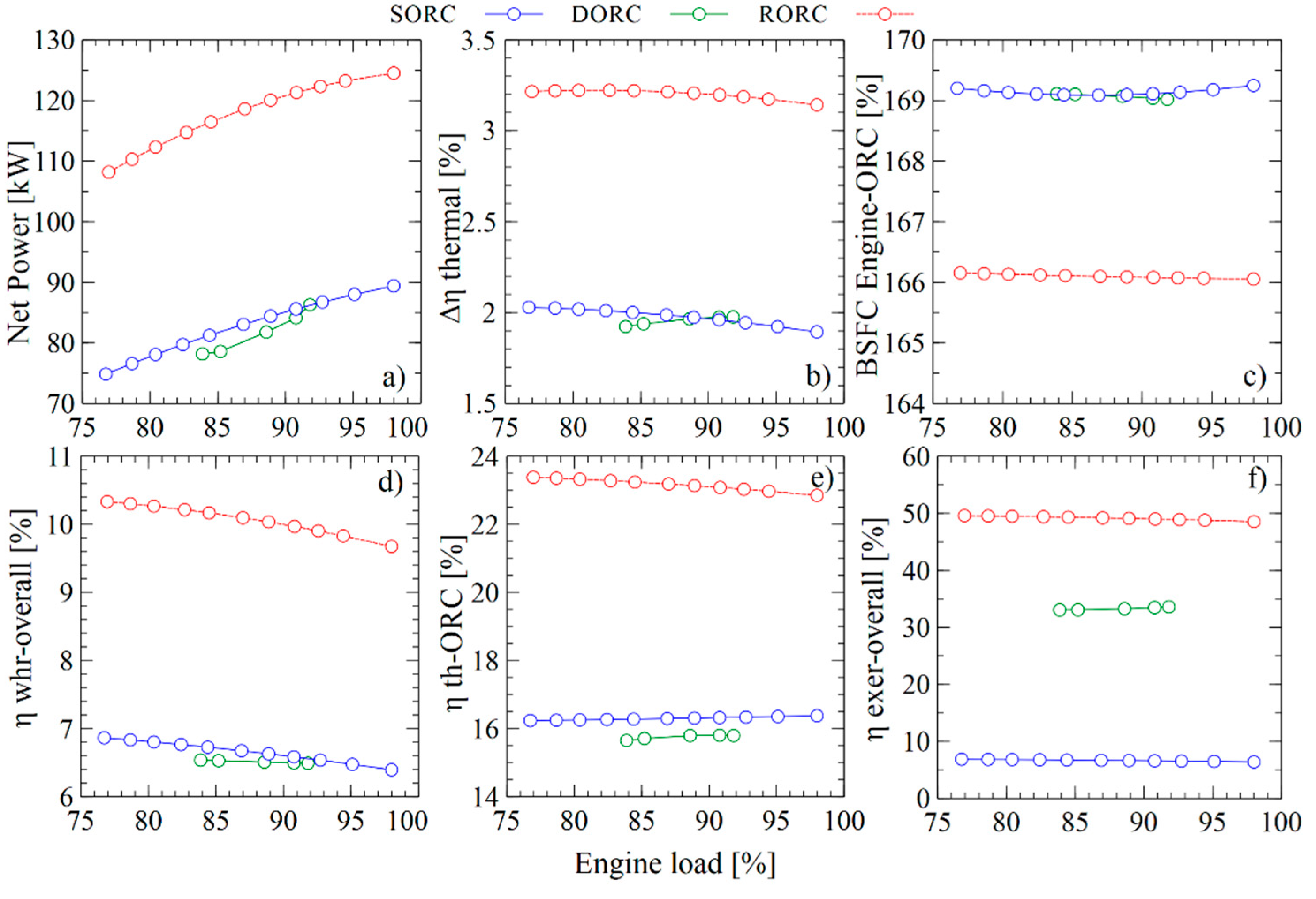
Table 1.
Main design and operation parameters of Jenbacher JMS 612 GS-N. L engine.
| Description | Value | Units |
|---|---|---|
| Cylinder capacity | 74.852 | L |
| Compression ratio | 10.5 | – |
| Number of cylinders (In V–60°) | 12 | – |
| Stroke length | 220 | mm |
| Diameter in chamber | 190 | mm |
| Maximum torque | 60.66 | kN⋅m |
| Power at nominal speed | 1820 | kW |
| Nominal speed | 1500 | rpm |
| Ignition system | Spark ignition | – |
| Minimum load capacity | 1000 | kW |
| Maximum load capacity | 1982 | kW |
| at minimum load | 1.79 | – |
| at maximum load | 1.97 | – |
| Exhaust gases O2 concentration | 9.45–10.52 | % volume |
| Exhaust gases CO concentration | 588–731 | mg/m3 |
| Exhaust gases NOx concentration | 461–468 | mg/m3 |
| Exhaust gases NO2 concentration | 317–368 | mg/m3 |
| Exhaust gases NO concentration | 65–95 | mg/m3 |
Table 2.
Fuel composition and supply conditions for the Jenbacher JMS 2 GS-N. L engine.
| Description | Value | Units |
| Methane (CH4) | 97.97 | % |
| Nitrogen (N2) | 1.50 | % |
| Ethane (C2H6) | 0.25 | % |
| Carbon dioxide (CO2) | 0.16 | % |
| Fuel–air mixture supply pressure | 1.15–1.25 | bar |
| Uncorrected volumetric ratio | 110–140 | L/s |
Table 3.
Parameters considered for internal combustion engines (ICE) simulation.
| Parameter | Value | Units |
|---|---|---|
| Gas flow | 120 | L/min |
| 1.784 | - | |
| 1482 | rpm | |
| Gas pressure | 1163.6 | mbar |
| Throttle valve | 80.0 | |
| Turbo bypass valve | 9.1 | |
| Gas temperature | 389 | °C |
| Engine coolant temperature | 63.9 | °C |
Table 4.
Performance indicators for ICE.
| Performance Indicators | Value | Units |
|---|---|---|
| Mechanical engine power | 1758.77 | kW |
| Effective engine efficiency | 38.59 | % |
| Heat recovery efficiency | 40.78 | % |
| Heat removed from exhaust gases | 514.85 | kW |
| Specific engine fuel consumption | 177.65 | g/kWh |
Table 5.
Parameters considered for proposed configurations (S = SORC, R = RORC, and DP = DORC).
| Configuration | Parameter | Value | Units | Reference |
|---|---|---|---|---|
| S/R/DP | Isentropic efficiency turbines | 80 | % | [38] |
| S/R/DP | Isentropic efficiency pumps | 75 | % | [38] |
| S/R/DP | Cooling water temperature (T1A) | 50 | °C | |
| S/R/DP | Pinch Point condenser (ITC3) | 15 | °C | |
| S/R | Pressure Ratio B1 | 2.5 | ||
| DP | Pressure Ratio B1 | 11.09 | ||
| S/R/DP | Pinch Point evaporators (ITC2) (ITC4) | 35 | °C | |
| R | Recovery Effectiveness (RC) | 85 | % | [38] |
| DP | Pressure Ratio B2 | 20 | ||
| DP | Pressure Ratio B3 | 9 | ||
| S/R | Pressure Ratio B2 | 30 |
Table 6.
Fuel-Product definition for each configuration.
| Component | Different Configurations of Waste Heat Recovery Systems Using ORC | ||||||||
|---|---|---|---|---|---|---|---|---|---|
| SORC | RORC | DORC | |||||||
| Fuel | Product | Lost | Fuel | Product | Lost | Fuel | Product | Lost | |
| I1 | . − | ||||||||
| B1 | . | - | - | - | |||||
| ITC2 | − | - | - | - | |||||
| T1 | - | - | - | ||||||
| ITC3 | - | . | - | - | - | - | |||
| B2 | - | - | - | ||||||
| RC | - | - | - | - | - | - | - | ||
| T2 | - | - | - | - | - | - | - | ||
| B3 | - | - | - | - | - | - | − | - | |
| ITC4 | - | - | - | - | - | - | - | ||
Table 7.
Data used from the system for model validation.
| Cycle | Tsource (°C) | F (kg/s) | (°C) | Pinch Point (°C) | (MPa) | ||
|---|---|---|---|---|---|---|---|
| SORC | 0.8 | 0.7 | 250 | 2.737 | 35 | 30 | 0.8–5.5 |
| RORC | 0.95 | 0.89 | 165 | 84.36 | 15 | 10 | 0.31 |
Table 8.
Validation of the proposed model for RORC.
| Parameters | Valencia et al. | Emam et al. [39] | Zare et al. [27] |
|---|---|---|---|
| 165 | 165 | 165 | |
| 84.36 | 84.36 | 82.16 | |
| 75.22 | 78.06 | 76.09 | |
| 394.21 | 399.30 | 390.60 | |
| 809.52 | 810.10 | 808.70 | |
| 124.58 | 124.80 | 124.20 | |
| 16.25 | 16.37 | 16.15 | |
| 48.71 | 48.80 | 48.54 |
Table 9.
Parameters of an integrated recovery system with engine and ORC. BSFC: brake-specific fuel consumption.
Table 9.
Parameters of an integrated recovery system with engine and ORC. BSFC: brake-specific fuel consumption.
| Parameters | SORC | RORC | DORC | Units |
|---|---|---|---|---|
| Thermal efficiency engine–ORC | 40.45 | 41.25 | 40.72 | % |
| Increased thermal efficiency | 1.86 | 2.66 | 2.13 | % |
| Thermal efficiency ORC | 16.40 | 23.51 | 18.74 | % |
| Global energy conversion efficiency | 6.68 | 9.59 | 7.66 | % |
| Global exergetic efficiency | 34.5 | 49.47 | 39.43 | % |
| BSFC engine–ORC | 169.5 | 166.21 | 168.42 | g/kWh |
Table 10.
Exergy analysis results for each component of the heat recovery system with SORC.
| Component | Input (kW) | Product (kW) | (kW) | Lost (kW) |
|---|---|---|---|---|
| ITC1 | 541.202051 | 202.794262 | 41.9535673 | 296.454222 |
| B1 | 0.37472727 | 0.05848531 | 0.31624196 | – |
| ITC2 | 202.852748 | 166.340104 | 36.5126437 | – |
| T1 | 99.4808146 | 85.5899807 | 13.8908338 | – |
| ITC3 | – | – | 36.0581887 | 66.5877282 |
| B2 | 0.75619324 | 0.58683347 | 0.16935977 | – |
Table 11.
Exergy analysis results for each component of the heat recovery system with RORC. RC: internal recovery unit.
Table 11.
Exergy analysis results for each component of the heat recovery system with RORC. RC: internal recovery unit.
| Component | Input (kW) | Product (kW) | (kW) | Lost (kW) |
|---|---|---|---|---|
| ITC1 | 541.202051 | 237.549898 | 7.197931 | 296.454222 |
| B1 | 0.36222219 | 0.09598314 | 0.26623905 | – |
| ITC2 | 237.645881 | 203.818309 | 33.827572 | – |
| T1 | 139.797975 | 122.396844 | 17.40113113 | – |
| ITC3 | – | – | 15.3197 | 71.5691491 |
| B2 | 0.94533621 | 0.7336153 | 0.21172091 | – |
| RC | 86.4902041 | 64.620999 | 21.8692051 | – |
Table 12.
Exergy analysis results for each component of the heat recovery system with DORC.
| Component | Input (kW) | Product (kW) | (kW) | Lost (kW) |
|---|---|---|---|---|
| ITC1 | 541.20 | 203.57 | 31.15 | 296.45 |
| B1 | 1.66 | 0.26 | 1.40 | – |
| ITC2 | 113.18 | 101.93 | 11.26 | – |
| T1 | 95.39 | 79.75 | 15.63 | – |
| ITC3 | – | – | 31.01 | 6.00 |
| B2 | 0.63 | 0.49 | 0.14 | – |
| T2 | 10.27 | 8.77 | 1.49 | – |
| B3 | 2.09 | 1.63 | 0.47 | – |
| ITC4 | 90.64 | 52.66 | 37.99 | – |
© 2019 by the authors. Licensee MDPI, Basel, Switzerland. This article is an open access article distributed under the terms and conditions of the Creative Commons Attribution (CC BY) license (http://creativecommons.org/licenses/by/4.0/).
Share and Cite
MDPI and ACS Style
Valencia, G.; Fontalvo, A.; Cárdenas, Y.; Duarte, J.; Isaza, C. Energy and Exergy Analysis of Different Exhaust Waste Heat Recovery Systems for Natural Gas Engine Based on ORC. Energies 2019, 12, 2378. https://doi.org/10.3390/en12122378
AMA Style
Valencia G, Fontalvo A, Cárdenas Y, Duarte J, Isaza C. Energy and Exergy Analysis of Different Exhaust Waste Heat Recovery Systems for Natural Gas Engine Based on ORC. Energies. 2019; 12(12):2378. https://doi.org/10.3390/en12122378
Chicago/Turabian StyleValencia, Guillermo, Armando Fontalvo, Yulineth Cárdenas, Jorge Duarte, and Cesar Isaza. 2019. "Energy and Exergy Analysis of Different Exhaust Waste Heat Recovery Systems for Natural Gas Engine Based on ORC" Energies 12, no. 12: 2378. https://doi.org/10.3390/en12122378
Note that from the first issue of 2016, this journal uses article numbers instead of page numbers. See further details here.