Article

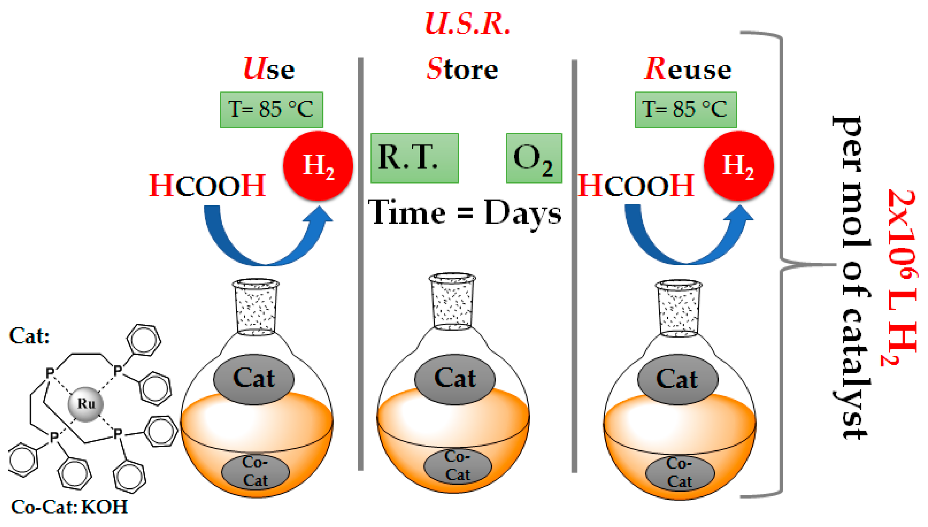
A Use-Store-Reuse (USR) Concept in Catalytic HCOOH Dehydrogenation: Case-Study of a Ru-Based Catalytic System for Long-Term USR under Ambient O2

by
Marinos Theodorakopoulos
1,
Maria Solakidou
2,
Yiannis Deligiannakis
2,3 and
Maria Louloudi
1,3,*
1
Laboratory of Biomimetic Catalysis and Hybrid Materials, Department of Chemistry, University of Ioannina, GR45110 Ioannina, Greece
2
Laboratory of Physical Chemistry of Materials and Environment, Department of Physics, University of Ioannina, GR45110 Ioannina, Greece
3
Institute of Environment & Sustainable Development, University Research Center of Ioannina, GR45110 Ioannina, Greece
*
Author to whom correspondence should be addressed.
Energies 2021, 14(2), 481; https://doi.org/10.3390/en14020481
Submission received: 28 December 2020 / Revised: 13 January 2021 / Accepted: 14 January 2021 / Published: 18 January 2021

Abstract

:
Commercial use of H2 production catalysts requires a repeated use/stop/store and reuse of the catalyst. Ideally, this cycle should be possible under ambient O2. Herein we exemplify the concept of Use-Store-Reuse (USR) of a (Ru-phosphine) catalyst in a biphasic catalytic system, for H2 production via dehydrogenation of HCOOH. The catalytic system can operate uninterrupted for at least four weeks, including storage and reuse cycles, with negligible loss of its catalytic efficiency. The catalytic system consisted of a RuP(CH2CH2PPh2)3 (i.e. RuPP3) in (tri-glyme/water) system, using KOH as a cocatalyst, to promote HCOOH deprotonation. In a USR cycle of 1 week, followed by storage for three weeks under ambient air and reuse, the system achieved in total TONs > 90,000 and TOFs > 4000 h−1. Thus, for the first time, a USR concept with a readily available stable ruthenium catalyst is presented, operating without any protection from O2 or light, and able to retain its catalytic performance.

Graphical Abstract

1. Introduction

Nowadays, fossil fuels & natural gas constitute the main sources of energy production [1]. Drawbacks regarding these resources relate to cost and environmental impact, i.e., air pollution and CO2 emission [2]. So far, molecular hydrogen (H2) has emerged as a highly promising alternative towards clean energy production [3,4], due to its high energy (2.6 higher than gasoline) and storage density (120 MJ kg−1). A strategic advantage of H2 use is that its combustion or fuel-cell utilization produces H2O as a sole byproduct [5,6]. The most promising methods for chemical-storage of H2 include liquid organic hydrogen-carriers (LOHCs) [7], under the condition that they would allow for a cost-efficient release of H2, i.e., via an efficient catalytic reaction. At present, the most attractive LOHCs include C1 hydrocarbons such as methanol, formaldehyde, and formic acid [8].
Specifically, Formic Acid (FA), is gaining a lot of attention in the scientific community as a promising route for H2 storage and release at competitive technology-readiness levels, i.e., under mild P, T conditions, and for its high gravimetric (4.4 wt.%) and volumetric (53.4 g/L) capacity [9,10,11].
The decomposition of FA can proceed via two possible paths [12], as described by Reaction Equations (1). Reaction Equation (1) has to be prevented, i.e., because CO is poisonous to the fuel-cells. Τhe desired reaction path in Equation (2) is thermodynamically allowed, ΔGo = −32.9 kJ/mol at high temperatures, however, is kinetically limited [13], thus a catalyst is needed to accelerate it.
HCO2H (l) → H2O (l) + CO (g) ΔGo = −12.4 kJ/mol
HCO2H (l) → H2 (g) + CO2 (g) ΔGo = −32.9 kJ/mol
Since 1967 when Coffey and his group published on the first Ir/Phosphine catalytic complex [14], much research works has been reported on dehydrogenation of FA, using homogeneous catalysts. In 2008, Beller et al. reported an efficient ruthenium catalyst, with the addition of a base as co-catalytic-additive, achieving TOFs = 301 h−1 [15]. Laurenczy et al., in 2009, presented a water-soluble (Ru (H2O)6)2+/TPPTS complex, achieving a TOF value of 444 h−1 [16]. In 2016, Huang et al. [17] presented a catalytic (Ru/PN3-pincer) complex in DMSO and DMF solvents; using triethylamine (Et3N) and Na2CO3 as co-catalytic-additives, this system achieved TOFs of 13,123 h−1 and 31,000 h−1,respectively [17]. A novel route for the dehydrogenation of formic acid was introduced by Beller et al. [18] using (Fe(BF4)2)∙6H2O as metal-precursor and tris((2-diphenylphosphino)ethyl)phosphine (P(CH2CH2PPh2)3 or PP3) as a phosphine ligand, achieving TOFs = 1962 h−1 in propylene carbonate at 60 °C, without any base additive [18]. Recently, we have exemplified that SiO2 nanoparticles can act as a very efficient co-catalyst for a Fe/(P(CH2CH2PPh2)3) complex [19]. This heterogeneous system achieved TOFs = 13,882 h−1, which is >10 times higher than the TOF of the corresponding homogeneous system (TOFs = 1205 h−1), without the co-catalyst [19].
Despite the encouraging progress in enhancing TOFs of H2-production catalysts, the long-term operation of a given catalyst remains a standalone challenge. This will have to be faced shortly when technology-readiness will require to advance beyond H2-production rates towards catalysts’ storage-reuse demands. In 2018, we described a phenomenon where amines grafted on SiO2 nanoparticles, i.e., ΝH2@SiO2 nanohybrids, provided a significant efficiency/stability boost to a Ru(PP3) catalyst [19]. Specifically, using (FA:{NH2 grafted on SiO2}) at ratio (500:1) the system Ru(PP3)/ΝH2@SiO2 achieved TOFs = 510 h−1 for uninterrupted operation over >16 h, under a continuous supply of formic acid [20]. Along the same lines, recently we demonstrated that “double-ligand” catalysts, e.g., Ru/PP3/Lγ and Fe/PP3/Lγ together with the ΝH2@SiO2 co-catalytic particles, were able to operate under a continuous FA feed, achieving remarkable total TONs of 6679 h−1 and 11,296 h−1, respectively [21].
Given that most of the catalytic systems suffer from a rather rapid deactivation of the catalyst and poor long-term stability performance, the development of stable catalysts under long-term applications, i.e., at a commercial level, is an appealing challenge. Within this context, so far, some efforts have been realized towards the development of continuous operating systems. This approach had been pioneered by Beller’s group, who had exemplified a long-term stability (RuCl2(benzene))2/dppe system, i.e., for a 30 h operating time [22]. Using as a base (N,N-dimethyl-n- hexylamine), they have reported a TOF~2000 h−1 [22]. Gonsalvi et al. [23] presented a Ru-tetra-phosphine-based catalytic system with a {meso-1,1,4,7,10,10-hexaphenyl-1,4,7,10-tetraphosphadecane} as ligand, in propylene carbonate solvent. Under a continuous formic acid feed, their system achieved TOFs = 4600 h−1 at 60 °C after 48 h; however, the system was sensitive to O2, thus it required an N2 atmosphere [23]. Huang et al. [24] used a water-soluble (Ru/N,N′-diamine) complex, operating under a continuous FA/HCOONa feed. This system required high-pressure conditions achieving TOFs = 12,000 h−1 after 30 h [24]. A catalytic system (Ru(H)(Cl)(CO)(CH3N{CH2CH2P(iPr)2}2)) in tri-glyme/water and KOH as a base-additive, was reported to achieve TOF = 4400 h−1 in 6 h under an argon atmosphere [25]. We underline that, in all the reported previous works, the uninterrupted long-term operation of the catalyst required operation under a strictly non-ambient atmosphere, i.e., exclusion of O2 by an inert gas, to avoid the decomposition of the catalytic complexes [22,23,24].
Herein, we present the first example of a Ru-catalytic system that can operate under long-term conditions under atmospheric O2, schematically depicted in Scheme 1. The catalytic system comprises of a (Ru-PP3) complex in a tri-glyme/water solution which contains formic acid partially deprotonated by KOH. As we show herein, this catalytic system was able to operate for seven sequential days under daily storage and reuse, followed by a three weeks storage and reuse. Remarkably, the catalytic system was active after one month showing a decrease of ~10% of its catalytic activity.

2. Materials and Methods

2.1. Materials

FA (purity 97.5% with 2.5% H2O), (RuCl3.(H2O)x) (ruthenium-III chloride hydrate, content 40.0–49.0%, purity 98%), Tris (2-(di-phenyl-phosphine)ethyl)phosphine (P(CH2CH2PPh2)3) (PP3) (98% purity), were purchased from Sigma Aldrich and kept under Ar atmosphere. Tri-ethylene glycol dimethyl ether (tri-glyme) solvent and KOH pellets (≥85%) were obtained from Merck.

2.2. Catalytic Procedures

Catalytic activity was evaluated in the same protocols as previous works [20]. In a typical catalytic experiment, 2 mg (9 μmol) of (RuCl3·(H2O)x) and 13.4 mg (20 μmol) of P(CH2CH2PPh2)3 (PP3).were dissolved in 2 mL tri-glyme solvent. The maximum incubation time for the formation of (Ru-phosphine) complex was 10 min (mixture 1, pre-catalyst) [20]. A solution of 2 mL formic acid (48 mmol), 1 mL water, 8 mL tri-glyme, and 0.55 g KOH (10 mmol) was heated in a glass reactor (mixture 2) at 85 °C for 20 min. Then, the pre-catalyst solution was added into the reactor (mixture 2) setting the starting point of the catalytic reaction. The volume of the evolving gas mixture was measured manually or by an automatic burette setup [20]. In all cases after the addition of (Ru-phosphine) (pre-catalyst) into mixture 2, the gas evolution was observed immediately. Quantification of produced gases was realized, directly after the addition of FA, inside an automatic gas burette at ambient atmosphere. The analysis of H2 and CO2 was made by a Shimadzu GC-2014 Gas Chromatograph combined with TCD detector and Carboxen-1000 column [20].

2.3. Characterization Techniques

Attenuated Total Reflection-FTIR (ATR-FTIR) experiments were recorded in situ, in the region of 400–2000 cm−1 by an Agilent spectrometer including a ZnSe-attenuated total reflection accessory. Raman measurements were performed with a Xplora one System Horiba PLUS instrument which employed an argon-ion laser at 532 nm diode as excitation source, from a range of 540 to 2000 cm−1. A liquid sample from the in-situ experiments was drop-casted on KBr pellets

3. Results and Discussion

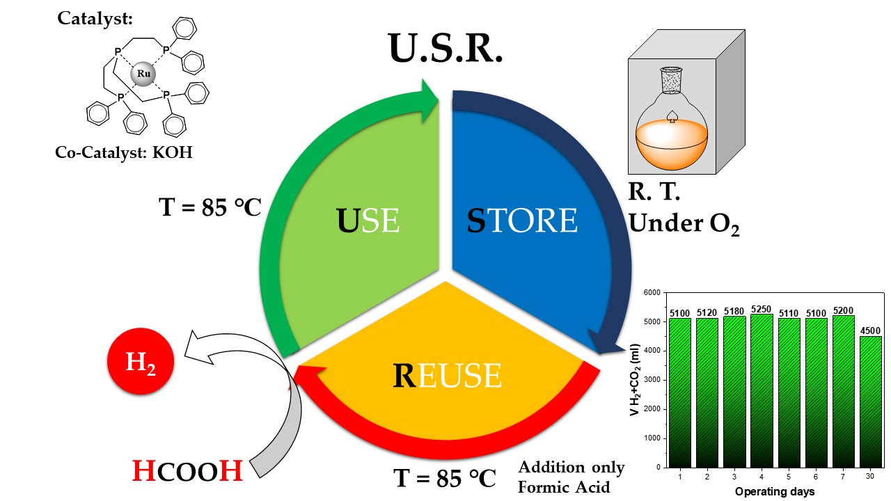
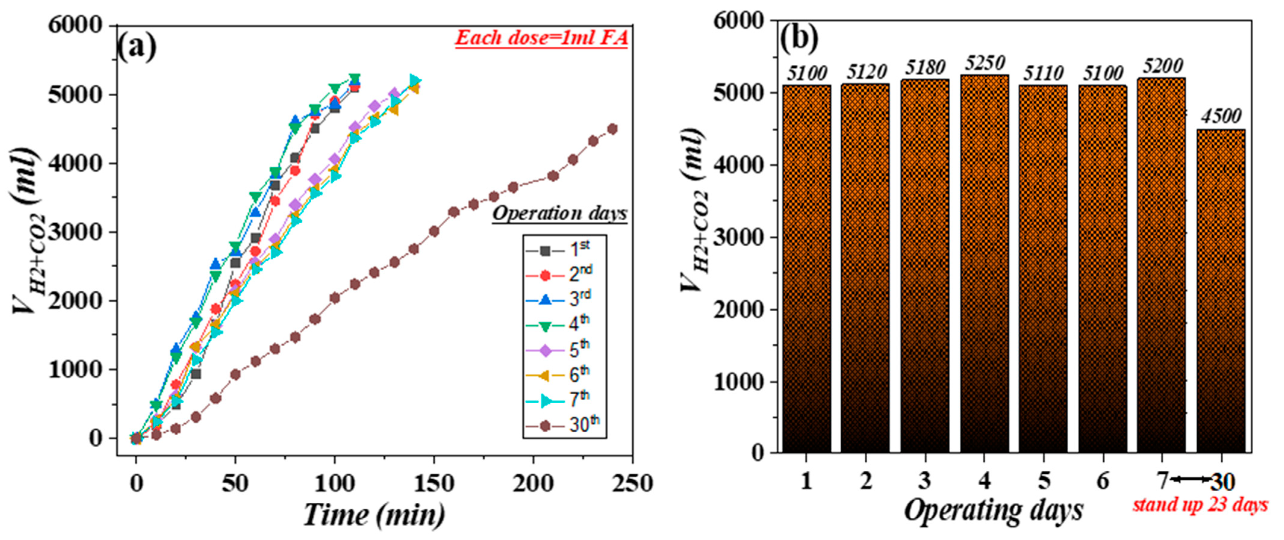
3.1. Operation Mode and Catalytic Data

The set-up of the optimum functional catalytic system used in this work includes the in situ formation of the (Ru-PP3) pre-catalyst with a molar ratio of (Ru):(PP3) = 1:2 and its addition in a water/tri-glyme (v/v = 1:8) solution, containing 2 mL of FA and 10 mmol of KOH which were added to promote deprotonation of a fraction of HCOOH. The catalytic systems derived from a molar ratio of (Ru):(PP3) equal to 1:1, 1:3, 1:4, and 1:5 have also been studied and the obtained data are provided in the Supplementary Materials (See Tables S1 and S2). We should underline that, in the 1:1 ratio, the complex has optimal activity. In catalysis, the existence of available non-occupied coordination sites is required in order to be active. To achieve the formation of the active complex 1:1 (Ru/PP3) in situ in all centers, we have added the second ligand in excess. Screening experiments showed that the optimum amount of KOH was 10 mmol, i.e., higher concentrations did not affect the H2 production rate. Gas GC-TCD analysis showed that during the whole catalytic procedure the only gases produced from FA decomposition were H2 and CO2 in the ratio 1:1 (Figure S1).
Daily operation: The catalytic procedure for one day was carried out as follows: addition of (Ru-PP3) (pre-catalyst) into the reactor which contains 2 mL of partially deprotonated FA at 85 °C, (see Scheme 1), initiated the catalytic reaction followed immediately by gas evolution. After the added FA was consumed (1ml of FA produces about 1.2 L of total gasses) another dose of FA (1 mL) was added and the system maintained the gasses’ production. After the addition of 5 sequential doses of FA (each dose 1 mL of FA, total 5 mL FA), the system was cooled down and kept in ambient conditions, without any protection against ambient oxygen or daily light.
Weekly operation: To restart the catalytic H2-production, i.e., next day, it was required to add only a new dose of FA (1 mL) and to reset the heating at 85 °C. In the same way, when the added FA was consumed, another dose of FA was added, and so on. After 5 added doses of FA (5 mL) were decomposed towards the production of gasses, the reactor was cooled down and kept in ambient conditions without any additional care. This process was carried out for seven sequential days.
Monthly operation: After the catalytic system had accomplished a weekly operation as described above, it was put in standby mode by cooling, with no FA added, under ambient P, T, for 3 weeks. Then, a month after the first operation of the catalytic system, a new dose of FA (1 mL) was added and upon heating at 85 °C the production of gasses started over again. Then, when the FA was consumed, another dose of FA was introduced into the reactor and so on, till 5 successive doses of FA had been added. The total volume of gasses produced from catalytic decomposition of FA by the (Ru/PP3) per day is presented in Table 1 and Figure 1. Each entry in Table 1 represents an operating day of the catalytic system. On Entry 1 the catalytic system decomposed in total 5 mL of FA (2 mL at the beginning, plus three additional doses of 1 mL each), providing in total 5.1 L of gas within 110 min and achieving TONs = 11468 and TOFs = 6267. During the second operation day (Entry 2), the same amount of FA (5 mL) was consumed within the same period (110 min), producing 5.12 L of gasses with TONs = 11513 and TOFs = 6291 h−1. In the same manner in Entry 3 and 4, the catalytic system maintained the same reactivity, where the produced gas volume was 5.18 L in 110 min with TONs = 11648 and TOFs = 6365 h−1,and 5.25 L with TONs = 11806 and TOFs = 6451 h−1 correspondingly On the fifth operational day, the catalytic system showed slight fatigue, since it required 140 min to consume 5 mL of FA; however, it produced the same volume of gasses (5.11 L) with analogous TONs (11,491), but with reduced TOFs = 4931 h−1. For the next two days, the catalytic system showed an analogous functional profile as ton he 5th day, i.e., 6th day: FA (5 mL), reaction time (140 min), gas volume (5.1 L), TONs = 11,468, TOFs = 4922 h−1; 7th day: 5 mL of FA, reaction time (140 min), gas volume (5.2 L), TONs = 11,693, TOFs = 5018 h−1. As mentioned above, after this operation the catalytic system was left at ambient conditions for 23 days and the catalytic system was retested for its ability to decompose FA. Thus, it was observed that it was able to produce 4.5 L of gasses from 5 mL of FA within 240 min with TONs = 10,119 and TOFs = 2529 h−1 (Table 1, Figure 1).From the above description, it is clearly demonstrated that the catalyst (Ru/PP3) remains unimpaired, showing a steady activity for a whole week, with gas production of 5.2 L/day, thus 36.0 L in total after a total operation time of 14.3 h (Figure 1b). At this point, it is underlined that, a month after the first use of the catalyst, it remained active, producing 4.5 L of gasses, i.e., a decline of catalytic performance of 13% vs. its initial performance. After the 5th operation day, the kinetics of H2 production showed a slight delay (see Figure 1a). This is reflected in the rate of gas production that was 70–80 mL/min for the first four operation days, vs. 50 mL/min measured on the 7th day, vs. 30 mL/min after a month (see Figure S2). The TOFs showed analogous trends i.e., as visualized in Figure 2 which presents the overall trends of TONs and TOFs values vs. operation days. The data in Figure 2 demonstrate the long-term stability and durability of the studied system, which accomplished up to 90,000 TONs. We should underline that a marginal diminution of 13% occurs only in the case of TOF (manifested by a drop in the catalytic rate). The TONs indicator remains just the same. This could be attributed to a minor deactivation of the catalyst, but the exact reason should be further investigated. Up to this point, the Electron Paramagnetic Resonance data (Supplementary material, Figure S4, spectrum (iv)) shows no RuII oxidation at the end of the reaction. Moreover, the formation of Ru-carbonyls could be confirmed via Raman and ATR spectroscopies, something that in our study is excluded. Another less plausible explanation could be the accumulation of water after the sequential additions of FA (2.5% (v:v) is contained in the FA stock, as obtained from the supplier). The same phenomenon was observed in similar studies [26,27].

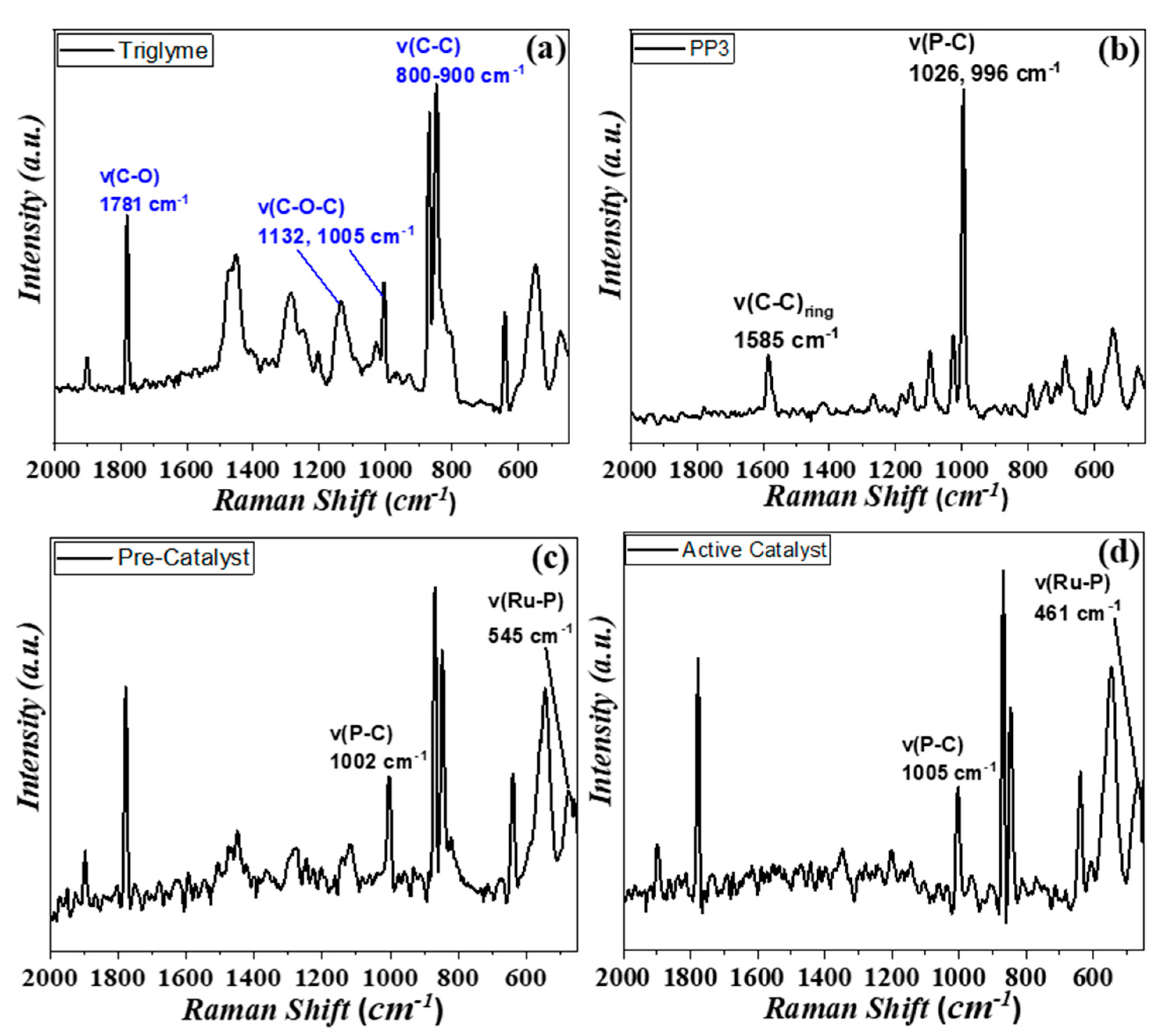
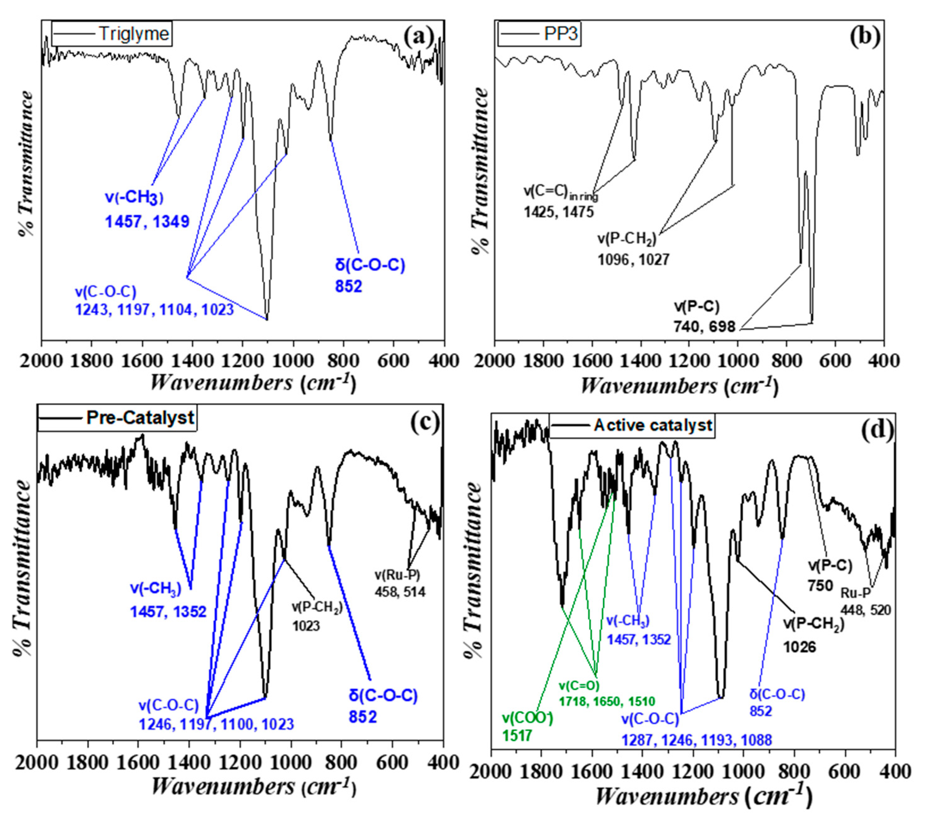
3.2. Spectroscopic Study of Catalysis In Situ

A more detailed study of the catalytic reaction, was realized using in situ ATR, Raman, and EPR spectroscopies. The obtained Raman and ATR spectra are provided in Figure 3 and Figure 4, respectively, where each one shows the spectrum of (a) tri-glyme solvent, (b) PP3 ligand, (c) [Ru-PP3] catalyst in tri-glyme, and (d) the full catalytic reaction system (Ru-PP3)/FA/KOH/tri-glyme:water solution (v/v = 10/1)}.
The v(C-C), v(C-O-C), and v(C-O) vibrations in the Raman spectra (see Figure 3a) and the δ(C-OC), v(C-O-C), and v(-CH3) bands in the ATR spectra (see Figure 4a) are attributed to the tri-glyme solvent. The intense frequency shifting, from 545 cm−1 to 461 cm−1 (Ru-P Streching), and from 996 cm−1 to 1002 cm−1 and 1006 cm−1, (P-C stretching bond) are attributed to the formation of the catalytic complex (Ru/PP3) (Figure 3c,d respectively).
The formation of the (Ru/PP3) complex and its presence in the catalytic reaction are affirmed by the ATR data, where the peaks at 468 cm−1 and 514 cm−1 in Figure 4c, and those at 448 cm−1 and 520 cm−1 in Figure 4d are attributed to the stretching Ru-P bond. Moreover, the EPR data confirm the formation of the RuIII/PP3 complex, (see signal (ii) in Figure S4). The EPR spectrum is a characteristic S = 1/2 low spin signal which confirms the oxidation state of RuIII [20,21]. The addition of the catalyst (Ru/PP3) in tri-glyme/water solution, which contained HCOO anions, i.e., due to HCOOH deprotonated by KOH, contributes to the diminution of the EPR signal (see spectrum (iii) in Figure S4), while, at the end of the catalytic reaction, the EPR signal of RuIII dropped to zero (see spectrum (iv) in Figure S4 RuIII). This is due to the reduction of RuIII to RuII, which is EPR silent [21]. At this point, we should mention that when the catalytic reaction was restarted, the EPR data (signal (v), Figure S4) did not show any oxidized RuIII-species, thus confirming the stability of the formed active RuII-catalyst.
When the catalytic reaction was monitored by ATR spectroscopy (see Figure 4d), the three characteristic bands at 1718, 1650, and 1510 cm−1 are attributed to the stretching of the C=O bond of FA, while the band observed at 1517 cm−1 is due to the stretching bond of the HCOO anion. These bonds also refer to the η1-O2CH and η2-O2CH modes of formic acid coordinated to the metal center [21,28]. According to previous studies [12,18,29], two possible catalytic cycles could be involved in the dehydrogenation of HCOOH, using a molecular homogeneous complex. In brief, Cycle-1 initiates with a HCOO anion and one HCOOH molecule, while Cycle-2 start with a HCOO anion in addition to a second formate anion (HCOO). We should mention that in both cases the involvement of β-hydride transfer from substrate to metal is the critical step. Yang, in his computational study, mentioned that Cycle-2 is less thermodynamically favorable than Cycle-1 [30]. Indeed, in most of the surveys, it is proposed that the involvement of a HCOO anion is more possible than the insertion of a HCOOH molecule [20,24,31,32].

4. Conclusions

In this work, we present the first example of the USR concept, using a (Ru-PP3) catalyst in tri-glyme. Raman, ATR, and EPR spectroscopies confirm that an initial key step is a reduction of (RuIII-PP3) to (RuII-PP3) which remained stable during catalysis with the involvement of FA.
The catalytic system was able to completely decompose five sequential doses of FA without the need for an additional KOH base. After, the reaction was stopped, stored (storage) at ambient conditions, and restarted (reuse) at will, with the addition only of a new amount of FA and reheating. These repetitive use/storage/reuse (USR) cycles occurred for a whole week, under ambient air, i.e., without any defense against atmospheric O2 and light. During this weekly operation, the catalytic system was completely active achieving 81,090 TONs with TOFs 5670 h−1. To test the system’s stability and durability, we stored it for an additional three weeks without any protection and the catalytic production was re-initiated by the addition of formic acid and heating.
Overall, the present work exemplifies the feasibility of the USR technology with a readily available, easy to handle, catalytic system.

Supplementary Materials

The following are available online at https://www.mdpi.com/1996-1073/14/2/481/s1.

Author Contributions

Conceptualization, M.L.; H2 production, M.T.; EPR spectroscopy, M.S.; Writing—original draft preparation, M.T. and M.L.; writing—review and editing, Y.D. and M.S.; supervision, M.L.; All authors have read and agreed to the published version of the manuscript.

Funding

This research received no external funding.

Institutional Review Board Statement

Not applicable.

Informed Consent Statement

Not applicable.

Data Availability Statement

Not applicable.

Conflicts of Interest

The authors declare no conflict of interest.

References

  1. Jacobson, M.Z. Review of solutions to global warming, air pollution, and energy security. Energy Environ. Sci. 2009, 2, 148–173. [Google Scholar] [CrossRef]
  2. Hansen, J. Climate sensitivity: Analysis of feedback mechanisms. Clim. Process. Clim. Sensit. 1984, 5, 130–163. [Google Scholar]
  3. Andreas, Z.; Borgschulte, A. Handbook of Fuels Beyond Oil and Gas: The Methanol Economy Molten Carbonate Fuel Cells, 1st ed.; Wiley-VCH: Weinheim, Germany, 2007; ISBN 9783527307401. [Google Scholar]
  4. Elam, C.C.; Padró, C.E.G.; Sandrock, G.; Luzzi, A.; Lindblad, P.; Hagen, E.F. Realizing the hydrogen future: The International Energy Agency’s efforts to advance hydrogen energy technologies. Int. J. Hydrogen Energy 2003, 28, 601–607. [Google Scholar] [CrossRef]
  5. Amende, M.; Kaftan, A.; Bachmann, P.; Brehmer, R.; Preuster, P.; Koch, M.; Wasserscheid, P.; Libuda, J. Regeneration of LOHC dehydrogenation catalysts: In-situ IR spectroscopy on single crystals, model catalysts, and real catalysts from UHV to near ambient pressure. Appl. Surf. Sci. 2016, 360, 671–683. [Google Scholar] [CrossRef]
  6. Jörissen, L. Hydrogen and Fuel Cells. Fundamentals, Technologies and Applications. Edited by Detlev Stolten. Angew. Chem. Int. Ed. 2011, 50, 9787. [Google Scholar] [CrossRef]
  7. Aakko-Saksa, P.T.; Cook, C.; Kiviaho, J.; Repo, T. Liquid organic hydrogen carriers for transportation and storing of renewable energy–Review and discussion. J. Power Sources 2018, 396, 803–823. [Google Scholar] [CrossRef]
  8. Crabtree, R.H. Hydrogen storage in liquid organic heterocycles. Energy Environ. Sci. 2008, 1, 134–138. [Google Scholar] [CrossRef]
  9. Joó, F. Breakthroughs in hydrogen storage\-formic acid as a sustainable storage material for hydrogen. ChemSusChem 2008, 1, 805–808. [Google Scholar] [CrossRef]
  10. Sheet, S.D. Formic acid Formic acid. ICIS Chem. Bus. 2017, 1, 1–12. [Google Scholar]
  11. Carra, S.; Santacesaria, E. Engineering Aspects of Gas-Liquid Catalytic Reactions. Catal. Rev. 1980, 22, 75–140. [Google Scholar] [CrossRef]
  12. Stathi, P.; Solakidou, M.; Louloudi, M.; Deligiannakis, Y. From homogeneous to heterogenized molecular catalysts for H2 production by formic acid dehydrogenation: Mechanistic aspects, role of additives, and co-catalysts. Energies 2020, 13, 733. [Google Scholar] [CrossRef] [Green Version]
  13. Onishi, N.; Laurenczy, G.; Beller, M.; Himeda, Y. Recent progress for reversible homogeneous catalytic hydrogen storage in formic acid and in methanol. Coord. Chem. Rev. 2018, 373, 317–332. [Google Scholar] [CrossRef]
  14. Coffey, R.S. The decomposition of formic acid catalysed by soluble metal complexes. Chem. Commun. 1967, 18, 923–924. [Google Scholar] [CrossRef]
  15. Loges, B.; Boddien, A.; Junge, H.; Beller, M. Controlled generation of hydrogen from formic acid amine adducts at room temperature and application in H2/O2 fuel cells. Angew. Chemie Int. Ed. 2008, 47, 3962–3965. [Google Scholar] [CrossRef] [PubMed]
  16. Fellay, C.; Yan, N.; Dyson, P.J.; Laurenczy, G. Selective formic acid decomposition for high-pressure hydrogen generation: A mechanistic study. Chem. A Eur. J. 2009, 15, 3752–3760. [Google Scholar] [CrossRef] [PubMed]
  17. Pan, Y.; Pan, C.L.; Zhang, Y.; Li, H.; Min, S.; Guo, X.; Zheng, B.; Chen, H.; Anders, A.; Lai, Z.; et al. Selective hydrogen generation from formic acid with well-defined complexes of ruthenium and phosphorus-nitrogen PN3-pincer ligand. Chem. Asian J. 2016, 11, 1357–1360. [Google Scholar] [CrossRef] [PubMed]
  18. Boddien, A.; Mellmann, D.; Gärtner, F.; Jackstell, R.; Junge, H.; Dyson, P.J.; Laurenczy, G.; Ludwig, R.; Beller, M. Efficient dehydrogenation of formic acid using an iron catalyst. Science 2011, 333, 1733–1736. [Google Scholar] [CrossRef] [Green Version]
  19. Stathi, P.; Deligiannakis, Y.; Louloudi, M. Co-catalytic enhancement of H2 production by SiO2 nanoparticles. Catal. Today 2015, 242, 146–152. [Google Scholar] [CrossRef]
  20. Solakidou, M.; Deligiannakis, Y.; Louloudi, M. Heterogeneous amino-functionalized particles boost hydrogen production from Formic Acid by a ruthenium complex. Int. J. Hydrogen Energy 2018, 21386–21397. [Google Scholar] [CrossRef]
  21. Solakidou, M.; Theodorakopoulos, M.; Deligiannakis, Y.; Louloudi, M. Double-ligand Fe, Ru catalysts: A novel route for enhanced H2 production from Formic Acid. Int. J. Hydrogen Energy 2020, 45, 17367–17377. [Google Scholar] [CrossRef]
  22. Boddien, A.; Loges, B.; Junge, H.; Gärtner, F.; Noyes, J.R.; Beller, M. Continuous hydrogen generation from formic acid: Highly active and stable ruthenium catalysts. Adv. Synth. Catal. 2009, 351, 2517–2520. [Google Scholar] [CrossRef]
  23. Mellone, I.; Gorgas, N.; Bertini, F.; Peruzzini, M.; Kirchner, K.; Gonsalvi, L. Selective Formic Acid Dehydrogenation Catalyzed by Fe-PNP Pincer Complexes Based on the 2,6-Diaminopyridine Scaffold. Organometallics 2016, 35, 3344–3349. [Google Scholar] [CrossRef]
  24. Guan, C.; Zhang, D.D.; Pan, Y.; Iguchi, M.; Ajitha, M.J.; Hu, J.; Li, H.; Yao, C.; Huang, M.H.; Min, S.; et al. Dehydrogenation of Formic Acid Catalyzed by a Ruthenium Complex with an N,N′-Diimine Ligand. Inorg. Chem. 2017, 56, 438–445. [Google Scholar] [CrossRef] [PubMed]
  25. Agapova, A.; Alberico, E.; Kammer, A.; Junge, H.; Beller, M. Catalytic Dehydrogenation of Formic Acid with Ruthenium-PNP-Pincer Complexes: Comparing N-Methylated and NH-Ligands. ChemCatChem 2019, 11, 1910–1914. [Google Scholar] [CrossRef] [Green Version]
  26. Stathi, P.; Deligiannakis, Y.; Avgouropoulos, G.; Louloudi, M. Efficient H2 production from formic acid by a supported iron catalyst on silica. Appl. Catal. A Gen. 2015, 498, 176–184. [Google Scholar] [CrossRef]
  27. Mellmann, D.; Barsch, E.; Bauer, M.; Grabow, K.; Boddien, A.; Kammer, A.; Sponholz, P.; Bentrup, U.; Jackstell, R.; Junge, H.; et al. Base-free non-noble-metal-catalyzed hydrogen generation from formic acid: Scope and mechanistic insights. Chem. A Eur. J. 2014, 20, 13589–13602. [Google Scholar] [CrossRef]
  28. Boddien, A.; Loges, B.; Gärtner, F.; Torborg, C.; Fumino, K.; Junge, H.; Ludwig, R.; Beller, M. Iron-catalyzed hydrogen production from formic acid. J. Am. Chem. Soc. 2010, 132, 8924–8934. [Google Scholar] [CrossRef]
  29. Sánchez-De-Armas, R.; Xue, L.; Ahlquist, M.S.G. One site is enough: A theoretical investigation of iron-catalyzed dehydrogenation of formic acid. Chem. A Eur. J. 2013, 19, 11869–11873. [Google Scholar] [CrossRef]
  30. Yang, X. Mechanistic insights into iron catalyzed dehydrogenation of formic acid: β-hydride elimination vs. direct hydride transfer. Dalt. Trans. 2013, 42, 11987–11991. [Google Scholar] [CrossRef]
  31. Léval, A.; Agapova, A.; Steinlechner, C.; Alberico, E.; Junge, H.; Beller, M. Hydrogen production from formic acid catalyzed by a phosphine free manganese complex: Investigation and mechanistic insights. Green Chem. 2020, 22, 913–920. [Google Scholar] [CrossRef]
  32. Mellone, I.; Bertini, F.; Peruzzini, M.; Gonsalvi, L. An active, stable and recyclable Ru(II) tetraphosphine-based catalytic system for hydrogen production by selective formic acid dehydrogenation. Catal. Sci. Technol. 2016, 6, 6504–6512. [Google Scholar] [CrossRef]
Scheme 1. Concept of U.S.R. (i.e., Use-Store-Reuse) technology. The catalytic system is set for H2-production at T = 85 °C (Use), stored under ambient P, T, O2 (Store), and Reused at T = 85 °C. The system during the whole operation (weekly and monthly) produced >2 × 10⁶ L of H2 per mole of catalyst.
Energies 14 00481 sch001
Figure 1. (a) Kinetics of gas production and (b) total gas volume produced every operation’s day. Conditions: (Ru/PP3) (9 μmol) in tri-glyme:water (v/v = 10 mL:1 mL) solution which contained FA and 10 mmol of KOH at 85 °C.
Energies 14 00481 g001
Figure 2. TONs and TOFs measured on each operation day. Conditions: (Ru/PP3) (9 μmol) in tri-glyme:water (v/v = 10 mL:1 mL) solution which contained FA and 10 mmol of KOH at 85 °C.
Energies 14 00481 g002
Figure 3. Raman spectra of (a) tri-glyme (solvent), (b) phosphine ligand (PP3), (c) (Ru/PP3) catalyst in tri-glyme and (d) catalytic reaction ([Ru/PP3]/FA/KOH in tri-glyme: water solution).
Energies 14 00481 g003
Figure 4. ATR-FTIR spectra of (a) tri-glyme (solvent), (b) phosphine ligand (PP3), (c) [Ru/PP3] catalyst in tri-glyme and (d) catalytic reaction ((Ru/PP3)/FA/KOH in tri-glyme: water solution).
Energies 14 00481 g004
Table 1. Catalytic data for formic acid (FA) decomposition by (9 μmol) of (Ru/PP3) in tri-glyme:water [v/v = 10:1] solution at 85 °C.
Entry *FA Added (mL)Produced Gas Volume (L)TONsTOFs (h−1)Reaction Time (min)
15 5.1011,4686267110
255.1211,5136291110
355.1811,6486365110
455.2511,8066451110
555.1111,4914931140
655.1011,4684922140
755.2011,6935018140
3054.5010,1192529240
* Each Entry represents the operating day of the catalytic system.
Publisher’s Note: MDPI stays neutral with regard to jurisdictional claims in published maps and institutional affiliations.

