Article

Experimental Validation of a Reduced-Scale Rail Power Conditioner Based on Modular Multilevel Converter for AC Railway Power Grids

1
School of Engineering, Campus of Azurém, University of Minho, 4800-058 Guimarães, Portugal
2
Faculty of Engineering, University of Porto, Rua Roberto Frias, 4200-465 Porto, Portugal
*
Author to whom correspondence should be addressed.
Energies 2021, 14(2), 484; https://doi.org/10.3390/en14020484
Submission received: 4 December 2020 / Revised: 9 January 2021 / Accepted: 14 January 2021 / Published: 18 January 2021
(This article belongs to the Special Issue Power Quality in Electrified Transportation Systems)

Abstract

:
Rail power conditioner (RPC) has the ability to improve the power quality in AC railway power grids. This power conditioner can increase the loading capacity of traction substations, balance the active power between the feeder load sections, and compensate for reactive power and current harmonics. At present, there is increasing use of multilevel converter topologies, which provide scalability and robust performance under different conditions. In this framework, modular multilevel converter (MMC) is emerging as a prominent solution for medium-voltage applications. Serving that purpose, this paper focuses on the implementation, testing, and validation of a reduced-scale laboratory prototype of a proposed RPC based on an MMC. The developed laboratory prototype, designed to be compact, reliable, and adaptable to multipurpose applications, is presented, highlighting the main control and power circuit boards of the MMC. In addition, MMC parameter design of the filter inductor and submodule capacitor is also explained. Experimental analysis and validation of a reduced-scale prototype RPC based on MMC topology, are provided to verify the power quality improvement in electrified railway power grids. Thus, two experimental case studies are presented: (1) when both of the load sections are unequally loaded; (2) when only one load section is loaded. Experimental results confirm the RPC based on MMC is effective in reducing the harmonic contents, solving the problem of three-phase current imbalance and compensating reactive power.

1. Introduction

Electric traction power systems are the main suppliers of electrical energy to electric locomotives, which normally operate with a higher power-to-weight ratio than conventional diesel locomotives [1]. Moreover, electric locomotives are less noisy and require less frequent maintenance than diesel locomotives [2]. However, when considering AC traction power systems, electric locomotives represent non-linear single-phase loads and adversely influence the power quality of the three-phase power grid [3]. Some of the problems related to power quality deterioration are the harmonic distortion produced by the electric locomotives and the negative sequence components (NSC) of currents created by the three-phase current imbalance of the power grid [4]. Numerous approaches to improve power quality have been developed and investigated in recent decades to overcome the deterioration of power quality in electrified railway systems [5,6]. In this regard, active power compensator-based power electronics converters are still in development for consistency with the latest evolution of high-speed electrified railway systems that broadly use 25 kV, 50 Hz power supplies [7]. For this reason, a power conditioner installed on a traction feeder, called a rail power conditioner (RPC), was introduced in [8]. The RPC system consists of two power converters (one power converter is connected for each traction feeder or load section) that provide the reactive power required by the traction loads, and maintain a unitary power factor on the three-phase power grid. In addition, the RPC shifts the active power from the highly loaded section to the lightly loaded section to maintain balanced active power between phases [9]. The RPC also compensates for the harmonics and the NSC of currents, consequently providing a robust power grid without perturbation and with a higher overloading capacity [10].
The typical RPC, presented in Figure 1, is composed of two back-to-back single-phase converters that are connected to the traction feeders (load sections) via two coupling transformers [10,11]. These transformers are important to step-down the load voltages and to achieve the necessary isolation between the RPC and the single-phase traction power grid [12]. However, these transformers significantly increase the total cost of the typical RPC solution. Moreover, the two-level back-to-back power converters are unscalable and should hold the total power of the RPC [13]. In this case, due to the low switching frequency of the power switching devices, harmonic content in the synthetized waveforms is presented in the low-frequency domain. These reasons may weaken the RPC performance, leading to a lower quality of synthesized waveforms and bulky grid-connected passive filters. Consequently, it is recognized that multilevel power converters are important to synthesize high quality waveforms and reduce the size of grid-connected passive filters [14].
In this context, the modular multilevel converter (MMC) is an attractive and promising solution for high power and custom power applications [15]. This is due to its salient features in terms of modularity, superior reliability, and high efficiency, and the reduced size of passive filters resulting from the low harmonic content in the multilevel voltage and current waveforms [16]. The modular structure means that MMC can scale to different power and voltage levels, and, in some applications, it can be a transformer-less configuration for grid-connected applications [17]. The MMC, in this paper, is composed of several low-voltage two-level converters, called submodules (SMs), connected in a cascade manner. Thus, the total MMC switching frequency is divided between the SMs, which results in low switching frequency for each device and reduced total switching losses. In addition, these cascade-connected SMs are capable of generating high-quality waveforms due to the reduced voltage stress and the utilization of low-voltage switching devices [18,19]. The MMC topology was first introduced in 2001 by the Marquardt Group for medium-voltage transmission applications. After 19 years of improvement, the MMC became the preferable multilevel converter topology for medium- and high-power applications [20]. Several MMC applications based on power electronics transformers in railway traction systems are presented in [21].
Many RPC topologies have been proposed in the literature using the MMC with high compensation capacity. For instance, an RPC based on a full-bridge back-to-back AC/DC/AC MMC and an open-delta (V/V) power transformer is presented in [22], an RPC based on a two-phase three-wire AC/DC/AC MMC and V/V power transformer is presented in [14,23], and an RPC based on an AC/AC MMC [24] and V/V power transformer is presented in [25]. In addition, authors in [26] present a classification of the RPC topologies. This paper mainly discusses the RPC based on a half-bridge AC/DC/AC MMC and V/V power transformer. The MMC is equipped with half-bridge SMs that only introduce positive voltage with a bidirectional current. At present, the majority of the marketed MMC projects are based on the AC/DC/AC MMC with half-bridge SMs. This is due to its lower costs, higher efficiency, and simple structure of the half-bridge SM compared to other types of MMC SMs [27].
The main contributions of the current paper are: (a) design and confirm the functionality of one half-bridge SM, including driver, protection, and power boards; (b) description of the implementation of a reduced-scale laboratory workbench of an RPC based on a half-bridge MMC and V/V power transformer; (c) experimental analysis of the proposed RPC based on MMC system considering two case studies—when two load sections are loaded and when only one load section is loaded; and (d) Presenting the main advantages of the implemented reduced-scale prototype in terms of power quality improvement in electrified railway systems. Validation of this prototype helps to predict the performance of the RPC based on MMC under high-power applications. The novelty of this paper is in the experimental analysis and validation of the proposed reduced-scale prototype RPC based on MMC.
This paper is organized as follows: Section 2 explains the rail power conditioner based on a modular multilevel converter (RPC based on MMC) and the related control algorithm. Section 3 presents the implementation of the proposed reduced-scale RPC based on MMC laboratory prototype. Section 4 presents the experimental results of the proposed reduced-scale RPC based on MMC prototype, considering two case studies: when two load sections are loaded and when only one load section is loaded. Finally, Section 5 summarizes the main conclusions of the developed work.

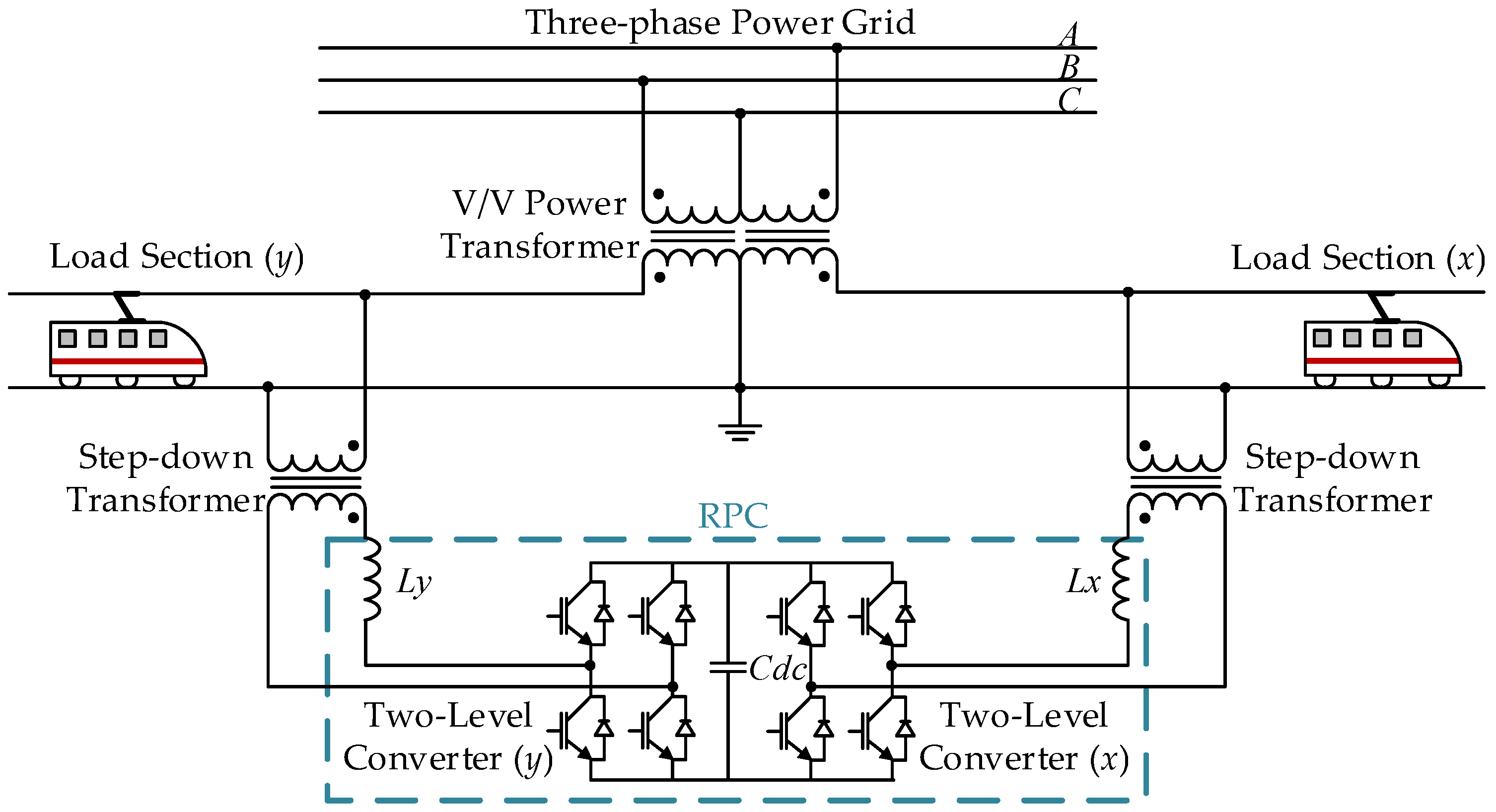
2. Rail Power Conditioner Based on an AC/DC/AC Modular Multilevel Converter and V/V Power Transformer

2.1. Rail Power Conditioner Topologies

In the literature, three types of RPC based on AC/DC/AC MMC exist: (a) an RPC based on a full-bridge back-to-back AC/DC/AC MMC and V/V power transformer as shown in Figure 2a; (b) an RPC based on a two-phase three-wire AC/DC/AC MMC and V/V power transformer as shown in Figure 2b; and (c) an RPC based on a half-bridge AC/DC/AC MMC and V/V power transformer as shown in Figure 2c. Many studies recommend using a half-bridge SM in the AC/DC/AC MMC and a full-bridge SM in the AC/AC MMC [28,29]. Therefore, the design and implementation process of the half-bridge SM is discussed in this paper. Reference [30] presents various MMC SM topologies, such as half-bridge SM, full-bridge SM, multilevel neutral point clamped SM, and multilevel flying capacitor SM. In the half-bridge SM, which is the simplest approach and the core of this study, each half-bridge SM, as shown in Figure 3, involves two power switching devices; in this example, we use the isolated gate bipolar transistor (IGBT), and one capacitor that could be inserted or bypassed. By comparison, filter inductors are important to limit the circulating currents between MMC arms and other harmonic content [31].
The RPC based on full-bridge back-to-back MMC, presented in Figure 2a, has the highest number of hardware components and the most complex control among the RPC based on MMC topologies. In addition, it requires isolation transformers to interface with the single-phase traction power grid because two of the RPC phases are connected to the same wire [23]. As a result, this solution is expensive when implemented as a reduced-scale laboratory prototype. In contrast, according to [26], the RPC based on a two-phase three-wire MMC and the RPC based on a half-bridge MMC have fewer components and require a smaller area for installation. They also can be classified as a special-purpose RPC because they are recommended to be used with only the V/V power transformer. For instance, using these topologies with a Scott power transformer requires a higher DC-link voltage and, therefore, using power switching devices with higher power ratings. Moreover, isolation transformers are not mandatory in these solutions because each phase of the RPC is connected to a single wire [26].
Due to the lower control complexity and the simple structure of the RPC based on half-bridge MMC, and because this topology saves 50% of the RPC based on full-bridge back-to-back MMC power devices, an implementation of a reduced-scale laboratory prototype was selected to validate the RPC based on half-bridge MMC configuration. In this context, [31] presents the control algorithm of the RPC based on half-bridge MMC using deadbeat predictive control and the associated simulation results. Reference [32] presents another possible control algorithm for the RPC based on half-bridge MMC using proportional-integral (PI) controllers and the related simulation results. In this paper, the control algorithms of the proposed RPC based on MMC, published in [31], are experimentally validated. The operation principle of the RPC and other operation modes are presented in [26]. In addition, a comprehensive comparison between the RPC based on MMC topologies is presented in [23]. Consequently, authors in [26,32,33] presented the control theory, operation principle, simulation results, and other comparative analyses of the RPC based on half-bridge MMC.

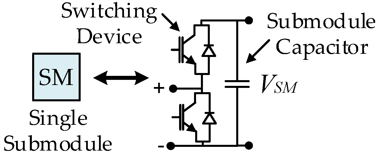
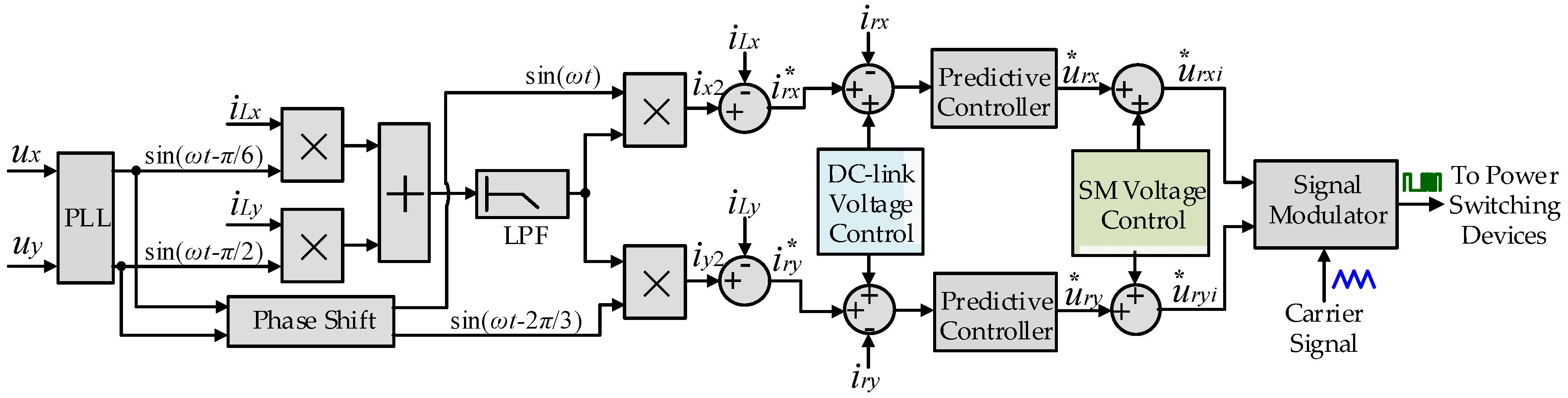
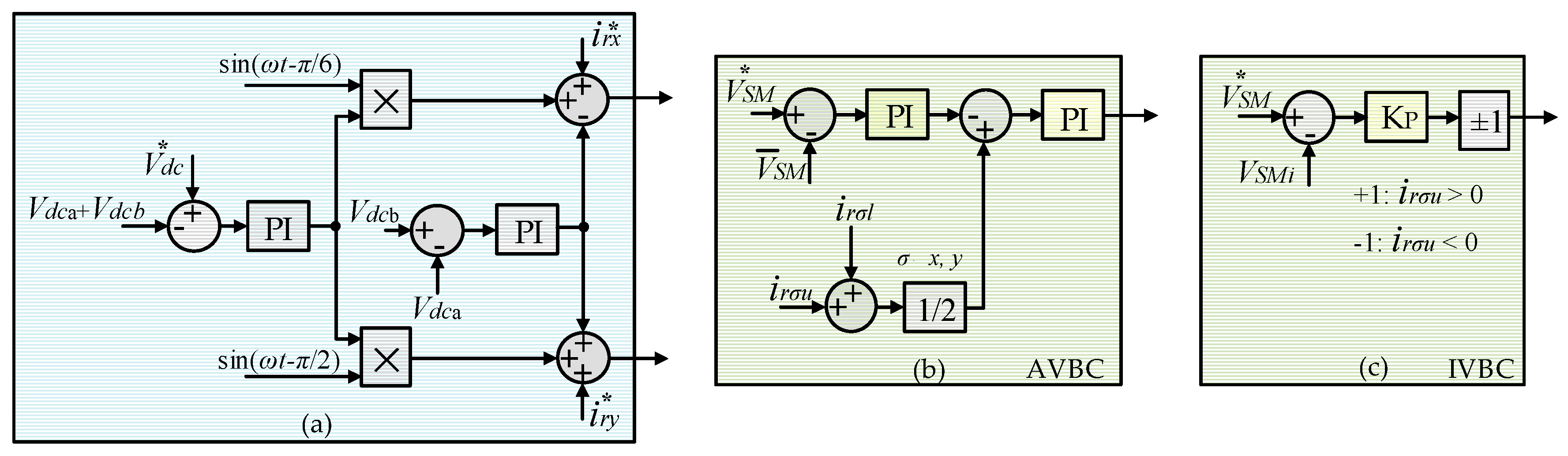
2.2. Rail Power Conditioner Based on Half-Bridge Modular Multilevel Converter Control Algorithm

One of the main objectives of the RPC based on MMC control algorithm is to calculate the compensation current references, i rx * ,   i ry * . Figure 4 shows the RPC based on half-bridge MMC and V/V power transformer control strategy. The compensation currents can be determined using the instantaneous load section currents iLx, iLy, where these currents are the most important variables because they are considered as the input signals for the control algorithm. There are two current sensors used on both load sections (x and y) to acquire the currents, iLx and iLy. Furthermore, a phase-locked loop (PLL) is essential to obtain the phase angles for both catenary voltages of ux and uy. More information about the PLL used can be found in [34]. The low-pass filter (LPF) is necessary to extract the DC current component resulting from multiplying the load section currents iLx, iLy with the correspondent sine waves in the V/V traction system, sin(ωtπ/6) and sin(ωtπ/2), respectively. In this case, the instantaneous currents of phase x and phase y after compensation ix2, iy2 are generated and, then, using Equation (1) the compensation current references, i rx * ,   i ry * are obtained. Detailed mathematical analysis and explanation of the establishment of the compensation current references can be found in [31,32].
i rx * = i x 2 i Lx i ry * = i y 2 i Ly
The MMC DC-link voltage control and SM voltage control are crucial to guarantee a good compensation performance. Because the DC-link voltage in the RPC based on half-bridge MMC is applied in two capacitors placed in series, voltage balance between these capacitors is necessary to obtain the neutral point between them. If the two DC-link capacitor voltages are unbalanced, it may cause voltage fluctuations and distortion in current waveforms [35]. A PI controller is thus used to correct the mismatch between the actual value of the DC-link voltage with its reference value. Another PI controller is applied to balance the voltages between the two DC-link capacitors, as shown in Figure 5a. The output of the DC-link voltage control is added to the compensation current references i rx * ,   i ry * . Then, a predictive controller is used to produce the compensation currents. Mathematical analysis of the RPC based on half-bridge MMC, including circulating current and predictive control analysis can be found in [31].
The SM voltage control in MMC consists of two control parts: averaging voltage balancing control (AVBC) and individual voltage balancing control (IVBC) [32]. The AVBC presented in Figure 5b ensures that the voltage for each SM in the MMC phase is close to the average voltage that is provided as a reference. It is implemented by adding the measured SM voltages for each MMC phase and dividing the result by the number of SMs per phase. The actual average voltage value, in this case, is calculated and compared to a reference average voltage, V SM * . Then, a PI controller is used to correct the difference between the actual and the reference values of the SM average voltage per MMC phase. The output of that PI controller is considered as a reference for a circulating current controller, which is implemented by summing the upper and the lower arm currents for each MMC phase irσu and irσl, where σ belongs to phase x or phase y. The second PI controller allows a low circulating current between the MMC phases [32]. By comparison, the IVBC forces the capacitor voltage of each SM to follow its reference, which is performed by a proportional controller for each SM. The output of the IVBC is multiplied by +1 if the arm’s current direction is to charge the capacitors, or by −1 if its direction is to discharge the capacitors [33]. The final signals of SM voltage control block are added to the final reference waveforms u rx * ,   u ry * to give the voltage command generation for each SM in phase x and phase y, u rxi * ,   u ryi * , where i refers to the number of SMs. Finally, the voltage command for each SM is applied to a signal modulator to drive the MMC power switching devices. Further details of the RPC control strategy can be found in [31] and [32].

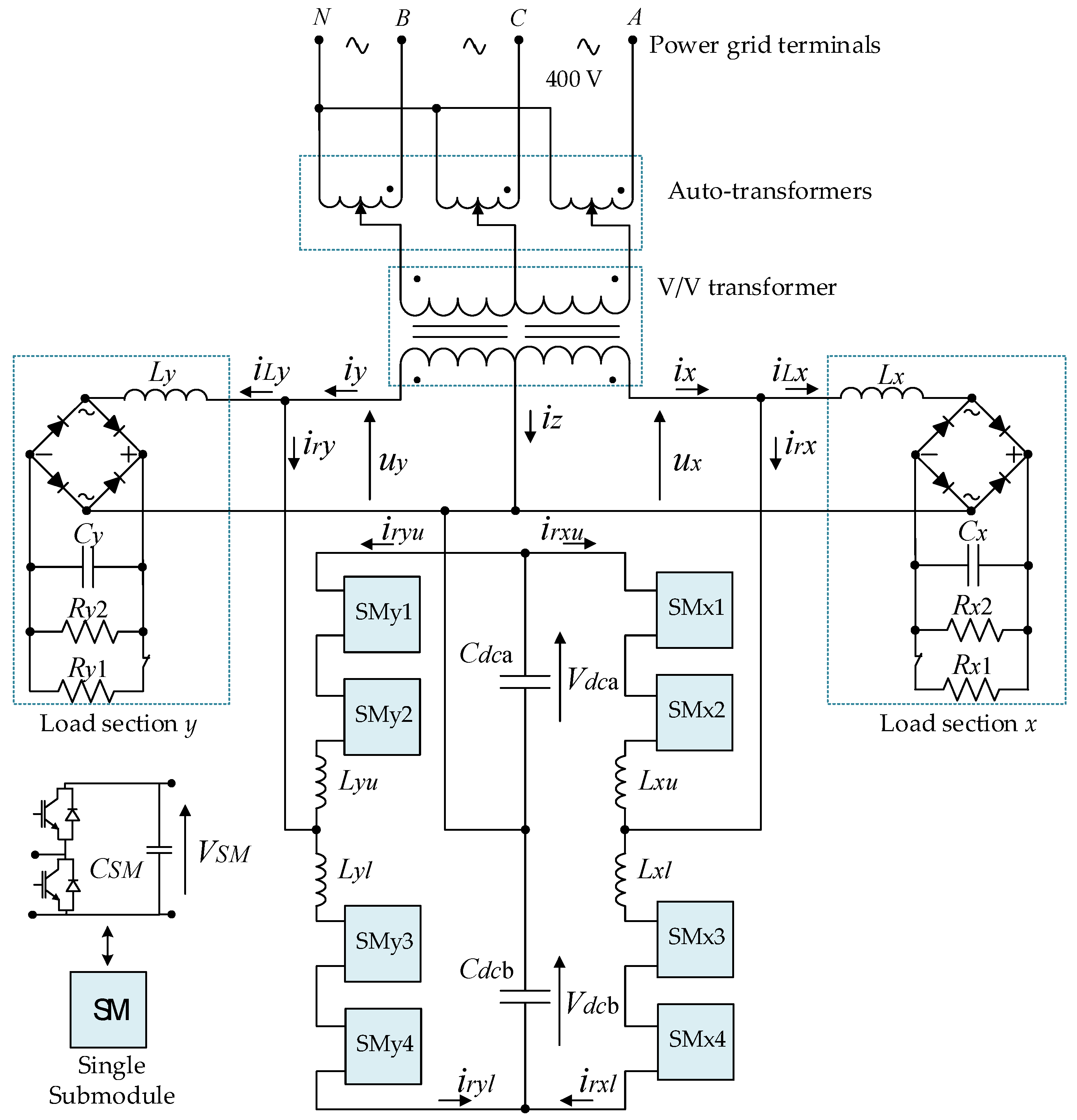
3. Implementation of a Reduced-Scale Laboratory Prototype RPC Based on Half-Bridge MMC

This section presents the main steps for the development of the reduced-scale RPC based on half-bridge MMC. The implemented prototype is developed to validate the RPC based on half-bridge MMC concept and the associated control algorithms. The main specifications of this prototype are selected and some of the hardware components are described in this section. Furthermore, design of the parameters of the reduced-scale RPC based on half-bridge MMC, such as the size of the MMC SM capacitor, the size of the filter inductors, and the size of the MMC main DC-link capacitor, are also presented in this section. Additionally, this section explains the SM structure, the control system hardware, and the supplementary power equipment. As is demonstrated, each SM consists of three boards: the driver circuit board, the protection circuit board, and the power circuit board. It should be noted that some of the components and systems have been oversized in order to ensure that, in the event of abnormal operation, safety is not compromised.

3.1. Parameters Design

The RPC based on the half-bridge MMC system, presented in Figure 2c, designed as a laboratory reduced-scale prototype, has eight SMs in total (four SMs in one MMC leg). The main objective of the implementation is to validate the RPC based on the half-bridge MMC topology, the proposed control algorithm, and the proposed MMC protection system. Consequently, a reduced-scale prototype with a few voltage levels is sufficient for a proof of concept. The prototype is implemented considering its operation in a two-phase V/V connection. In addition, the implementation is carried out considering that the converter will be used for the purpose of power quality improvement. In the V/V traction system configuration, the total DC-link voltage of the RPC based on half-bridge MMC should have a value at least twice that of the load section peak voltages due to the half-bridge configuration [32]. In this section, the main guidelines and principles for design of the MMC filter inductance, the main DC-link capacitor, and the SM capacitor are presented.
The design of the filter inductance directly influences the control system capability to track the compensation current references. In addition, the current ripples depend on the voltage applied on the inductance, the value of the inductance, and the time that the voltage is applied. The inductance can be designed by considering the factors of current ripple suppression and the speed of signal tracking [36]. The filter inductance operates as an inner MMC filter to attenuate high-frequency harmonics in the arm current and to limit the DC-link short circuit current [16]. Moreover, sizing the filtering inductance requires taking into account the suppression of undesired low-frequency harmonics, such as the MMC circulating current that is mainly composed of the 2nd order harmonics [37,38]. According to [32,39], the equation that determines the value of the filter inductance, Lσ(u,l); σ ∈ {x, y} is presented in Equation (2), where, Vdc is the total DC-link voltage of the MMC, VSM is the SM DC-link voltage, f is the traction power grid fundamental component frequency, Irσ(u,l); σ ∈ {x, y} is the MMC arm current, fsw is the switching frequency, and Δ Irσ(u,l) is the MMC arm current ripple.
V S M 8   f sw   Δ   I r σ ( u , l ) L σ ( u , l ) V dc 2 4 V SM 2 2 π   f   I r σ ( u , l )
A low value of the SM capacitor implies high-voltage ripples. Alternatively, a high value of capacitance results in an expensive and bulky MMC prototype [40]. The bulky converter requires a bigger area for installation. Thus, the previous principle is taken into account in the selection process of the SM capacitor value, where this value is estimated by considering the trade-off between the size, costs, and voltage ripple [16]. Furthermore, according to a study presented in [39], there is a resonance point related to the filter inductance and the DC-link capacitor of each SM, in which the maximum value of the resonance angular frequency should always be smaller than the fundamental frequency to avoid the resonance phenomenon. As a result, the resonance frequency that is related to the filter inductance and the SM capacitor should be considered in the MMC design process. According to [32,39], the equation that calculates the minimum capacitance of each SM capacitor is presented in Equation (3), where Lσ(u,l) is the filter inductance, N is the MMC voltage level, (N − 1) is the number of SMs in one MMC arm, n is the modulation index, Uσ (peak) is the peak voltage value of the catenary voltage, Vdc is the MMC DC-link voltage, and f is the power grid fundamental component frequency.
C SM > 3 ( N 1 ) + 2 ( N 1 )   n 2 48   ( 2 π   f ) 2   L σ ( u , l )
n = 2 U σ   ( peak )   V dc ;   σ { x ,   y }
Because the main DC-link voltage is always equal to (N − 1) times of a single SM voltage as presented in Equation (5), in the half-bridge MMC, the size of the main DC-link capacitor should be at least (N − 1) times the SM capacitor value [39]. Choosing the right value of the main DC-link capacitor is important because this value determines the converter power capacity, thus guaranteeing the ability of the RPC based on half-bridge MMC to compensate reactive power and harmonics, and to shift half of the active power difference between the load sections. In this regard, the main DC-link power should cover the MMC power losses, plosses, and the AC power of the converter, pac, as presented in Equation (6) [16].
Vdc*= VSM* (N − 1); N: MMC voltage levels
p dc = p ac + p losses v dc   i dc = σ = x ,   y u σ   i r σ + p losses
The instantaneous power provided by each capacitor of the main DC-link, pdca, can be expressed by Equation (7), where Wdca is the energy stored in the DC-link capacitor, Cdca is the capacitance of the DC-link capacitor, and vdca is the DC-link voltage.
p dca = dW dca dt = d ( 1 2   C dca   v dca 2 ) dt = v dca   C dca   dv dca dt
Then, it is possible to define Equation (8), which gives the minimum capacitance of the main DC-link capacitor, where fd is the DC-link voltage ripple frequency (twice the fundamental frequency in the full-bridge converter and equal to the fundamental frequency in the half-bridge converter), Cdca(min) is the minimum capacitance of the DC-link capacitor, and ΔVdca is the DC-link voltage ripples (peak-to-peak).
C dca ( min ) P dca   V dca   Δ V dca   f d
The active power difference between the load sections in the reduced-scale prototype varies between 0 and 1500 W. The converter shifts half of the active power difference between sections. Therefore, the worst-case scenario is when only one load section is loaded when the converter shifts a higher value of active power between the load sections. In this context, it is possible to consider the parameters (Pdca = 750 W, fd = 50 Hz; Vdca = 200 V; ΔVdca = 30 V), then, the minimum capacitance for one DC-link capacitor, as presented in Equation (8), should be equal to or greater than 2.5 mF.
The final MMC parameters of the reduced-scale prototype are presented in item 4. These are calculated with regard to Equations (2), (3) and (8). By considering the root-mean square (RMS) voltage value of the load section voltages 100 V and fundamental grid frequency of 50 Hz, and by supposing the maximum RMS value of the MMC arm current Irσ(u,l) = 20 A, then the filter inductance value should be within the range of 0.1 mH ≤ Lσ(u,l) ≤ 10 mH. Consequently, by applying this range in Equation (3), the SM capacitance should be higher than 100 µF.
In the RPC based on half-bridge MMC reduced-scale prototype, only eight SMs with high switching frequency will be used to reduce the MMC complexity. The used switching frequency is 40 kHz, which allows a sinusoidal waveform to be synthesized with very good quality and fast dynamic response when compensating load current harmonics. However, in high-power applications, a few tens of SMs with low switching frequency can be used to achieve the same objectives.

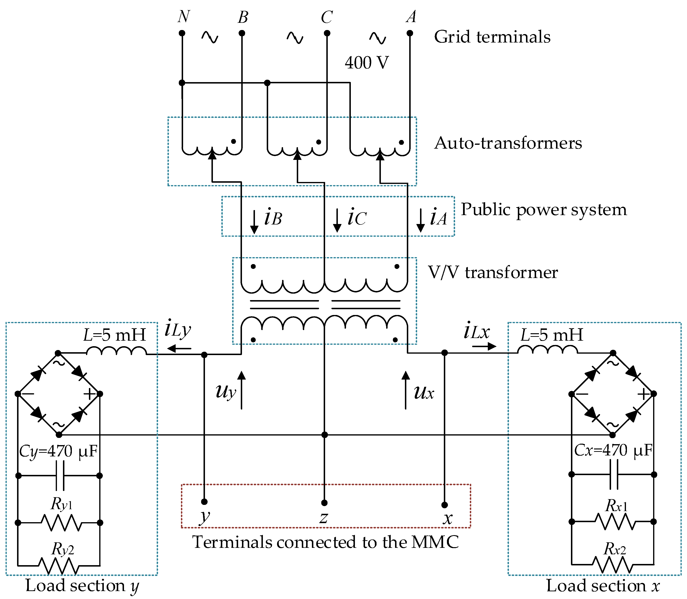
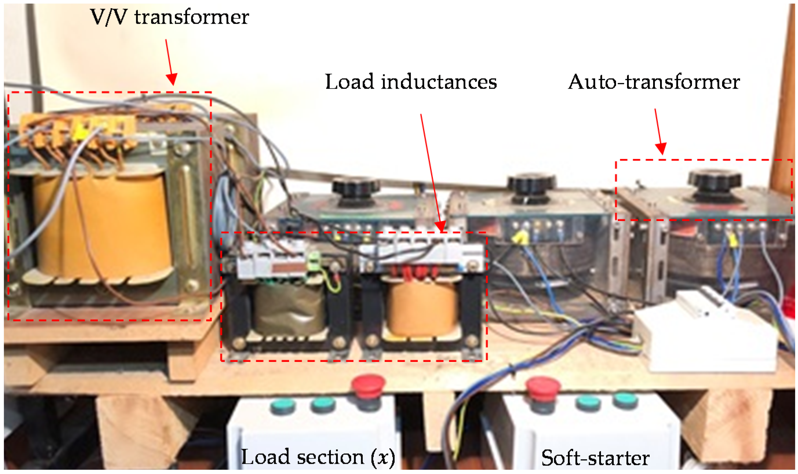
3.2. Supplementary Power Equipment

The implemented reduced-scale prototype mainly consists of the power system and control system hardware. This section describes the supplementary power hardware used to obtain a reduced-scale traction power grid. Figure 6 shows a diagram of the supplementary power equipment used to obtain the three-phase public power grid and the two-phase traction power grid after using a V/V transformer. The objective is to have two-phase voltages, Ux and Uy with 60° out-of-phase due to the V/V connection [41].
Figure 7 shows the supplementary power equipment setup. Three single-phase auto-transformers are used to change the voltage magnitudes of Ux and Uy. The connection must be carried out after respecting the phase order as shown in Figure 6. The output voltages of the auto-transformers (input voltages of the V/V transformer) must be in phase with the line-to-line voltages, UAC and UBC, to have a phase shift of 60°, as presented in Equation (9).
One of the V/V connection advantages is its easy implementation in the laboratory. Hence, single-phase step-down transformers are used to implement the V/V connection and to obtain two-phase voltages, Ux and Uy, as presented in Equation (9). Attention to the polarity of the single-phase transformers must be considered to obtain the correct phase shift. These single-phase transformers have a turns ratio of 0.5. In this case, the point z, as shown in the Figure 6, is the neutral of the reduced-scale traction power grid. Each load section is connected to an inductance and a full-bridge rectifier. The inductances are important to represent the non-linear inductive traction load. The indicated values in Figure 6 are used in the real implementation.
Because the single-phase auto-transformers have a large magnetization inductance value, a soft-starter is required to avoid high inrush currents at the moment of connection to the power grid. This soft-starter inserts series-connected resistors into the auto-transformers input, and a timer contactor is used to bypass the series-connected resistors after a predefined period.
The main purpose of the supplementary power equipment is to have different load power values to show the capability of the RPC based on half-bridge MMC in improving the three-phase grid power quality. The resistors, Rx1 and Ry1, have a small value and mainly determine most of the consumed power in each load section. On the contrary, the resistors, Rx2 and Ry2 have a high value because the main purpose of these resistors is to dissipate the stored energy in the capacitors for safety reasons after turning off the power supply or disconnecting the load resistors of Rx1 and Ry1 using contactors.
U ˙ A = 230     0 ° ;   U ˙ B = 230   120 ° ;   U ˙ C = 230   240 °   ( V ) U ˙ AC = 400   30 ° ;   U ˙ BC = 400   90 °   ( V )

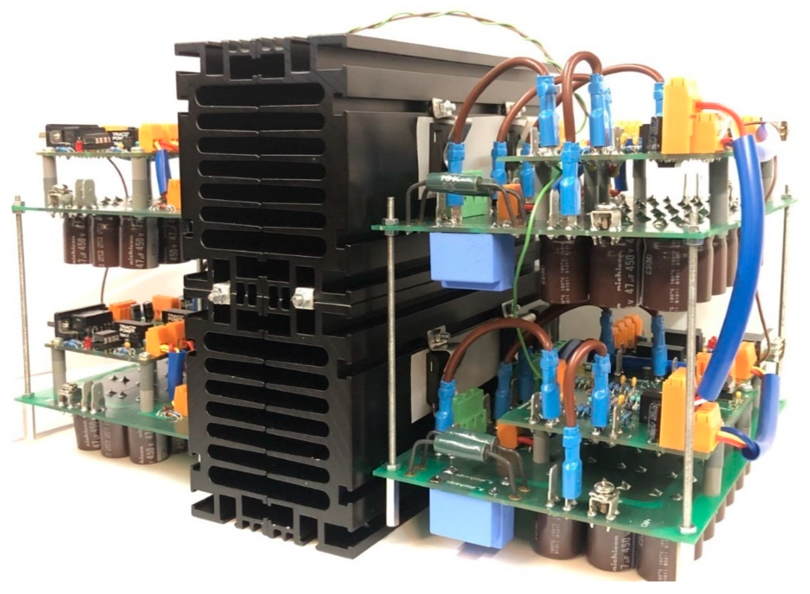
3.3. Implementation of a Reduced-Scale Modular Multilevel Converter

This section presents the implementation of the reduced-scale MMC, including the SM components. Initially, the main aim is to implement a well-designed SM, then replicate the work to have a full MMC. For this purpose, various tests should be employed on the designed SM before implementing the final MMC. This is essential to guarantee a robust performance under abnormal conditions when several cascade-connected SMs are under operation. Consequently, this item presents the MMC design process, including the SM implementation and validation.

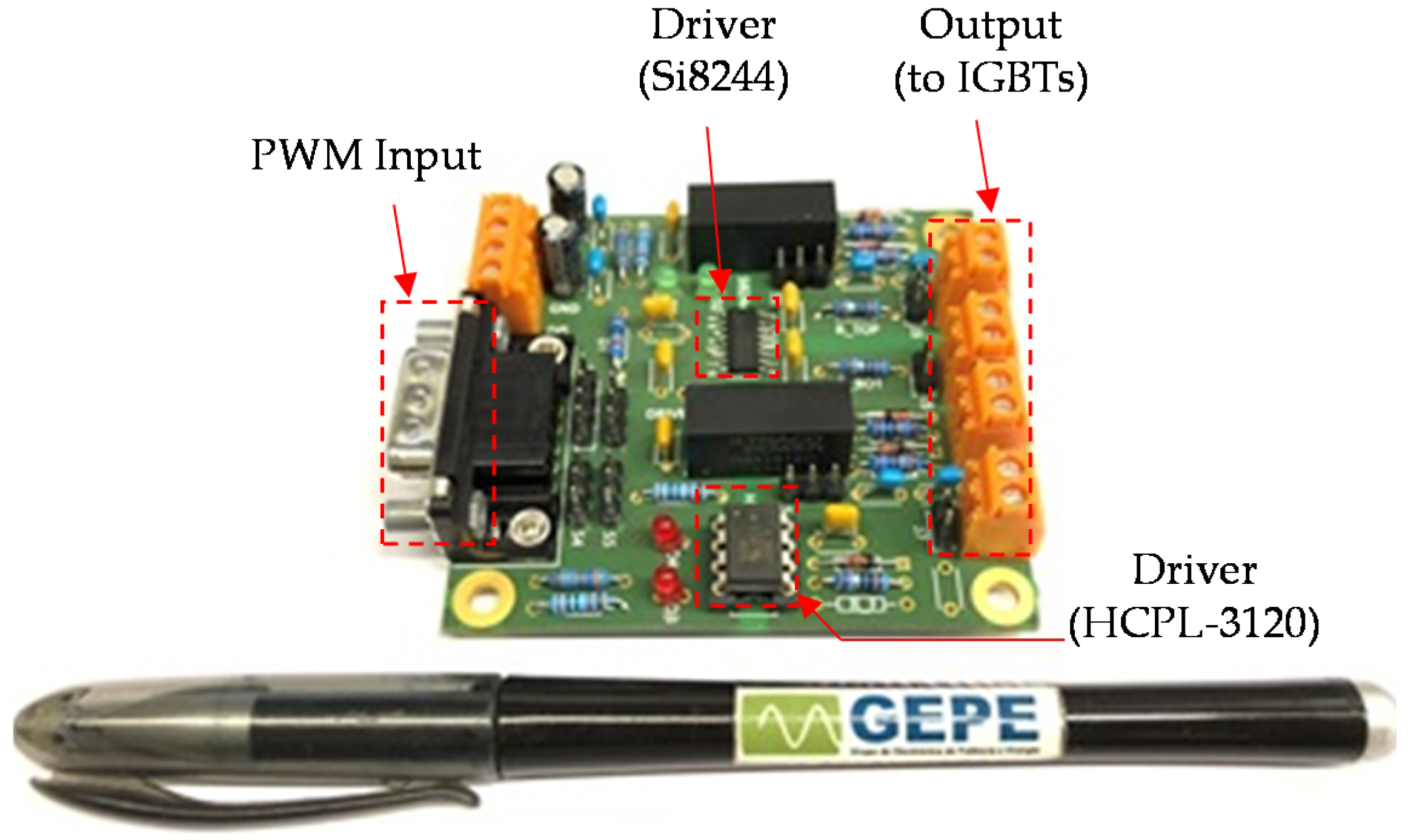
3.3.1. IGBT Driver Circuit Board

The main application of the driver board is to drive the SM switching devices. In this context, an isolated driver with two complementary channels in a single package is used (SI824x from Silicon Labs [42]). This driver is specifically targeted to drive complementary switching devices (as in the case of half-bridge power converter developed). In addition, its main feature is the integrated deadtime generator between the high-side/low-side drivers that allow highly precise control for achieving optimal total harmonics distortion (THD). Another driver, HCPL-3120, is employed to drive an additional IGBT switch for the purpose of overvoltage protection, as explained in Section 3.3.2. Figure 8 shows the driver circuit board hardware. The pulse width modulation (PWM) input signals are supplied from the main central control unit and the outputs of this board are connected to the gate-emitter of each IGBT that composes the SM.
The driver circuit board is designed using an optimized layout to reduce the length of the board traces. That is, the design should respect the minimum compulsory dimensions to maintain the isolation between the channels. In addition, the optimized layout is important to minimize the board parasitics, such as parasitic inductance and capacitance, thus reducing noise and improving the board performance. This is possible by decreasing some signal loops and keep connections as short as possible. Moreover, decoupling capacitors located close to the main power supply signals are used to avoid erroneous operation. Furthermore, extra jumpers are added, allowing the voltage value (either 0 V or −15 V) of the IGBT switching device to be turned off. The turn-off negative voltage applied to the gate-emitter junction helps to decrease the turn-off time of the IGBT, thus improving the overall performance and obtaining a faster switching device.

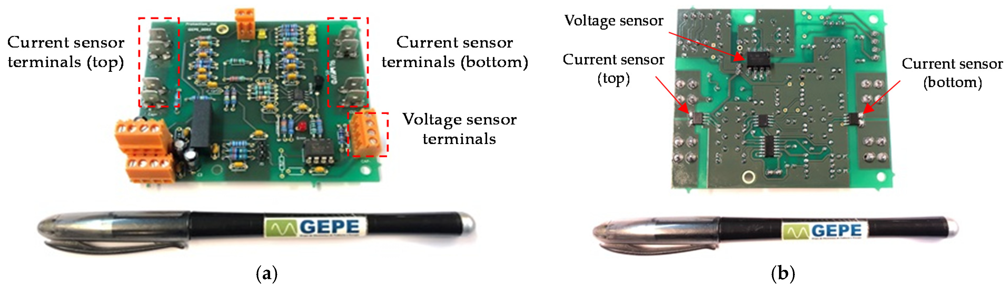
3.3.2. Protection Circuit Board

MMC reliability and stability are some of the most important demands. This includes protection against consequences that may appear due to the MMC malfunctioning, bearing in mind that the MMC topology contains many power switching devices, such as an IGBT and diodes, and each device can be a possible failure point. Because the MMC is composed of multiple cascade-connected SMs, each SM should have its own protection system; thus, the developed protection circuit board is essential for each MMC SM. Figure 9 shows the developed protection board, which is applied to each MMC SM. This protection consists of two main parts: overcurrent protection and overvoltage protection. A detailed description of this overvoltage and overcurrent protection with experimental results is presented in [43].
It is worth noting that several protection systems are implemented, either by means of implemented boards, such as the protection circuit board, or through verification functions in the developed supervision software. In addition, four semiconductor fuses are used as ultimate protection, where each MMC arm has one semiconductor protection fuse.

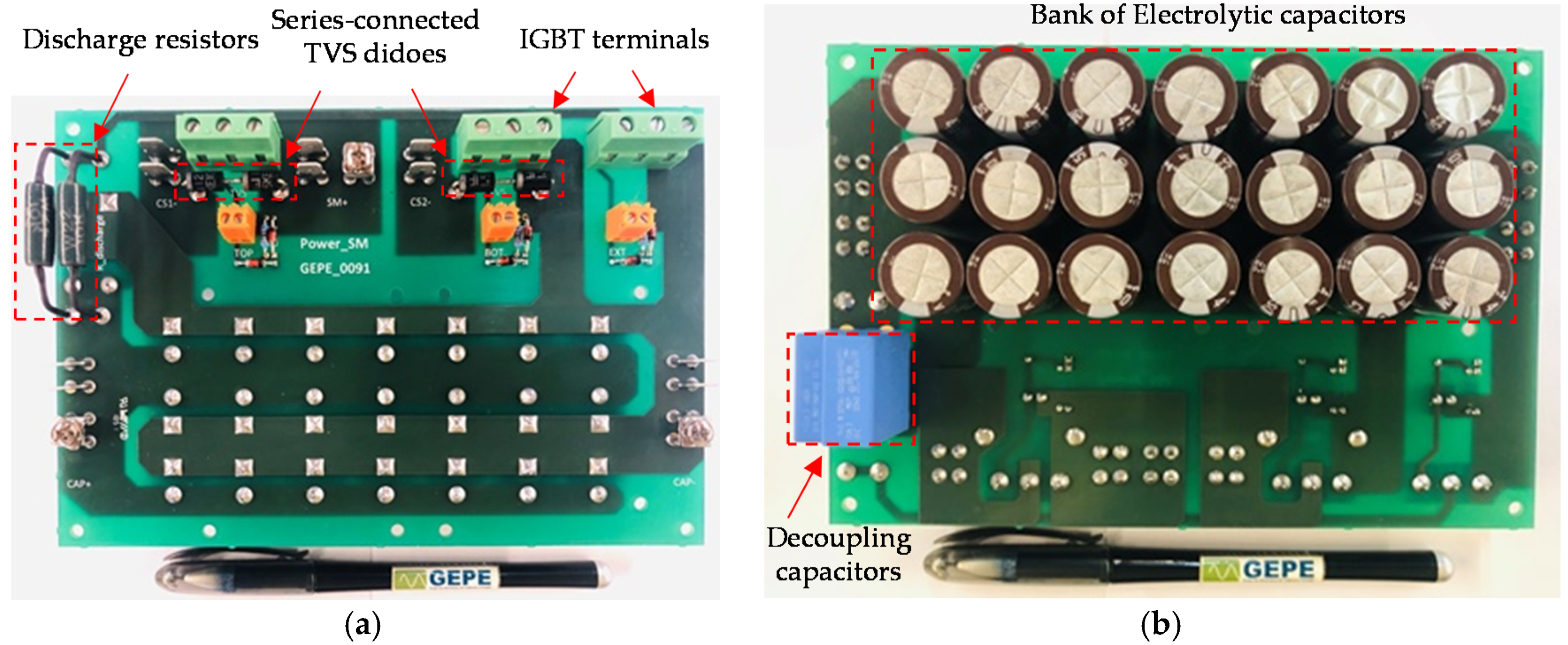
3.3.3. Power Circuit Board

The power circuit board includes the half-bridge SM components, such as DC-link capacitors, coupling capacitors, power switching devices, discharge resistors, and power terminals. Three power switching devices, IGBTs, are mounted on the top surface of the power circuit board, where two of these switching devices commutate at 40 kHz switching frequency to synthesize output waveform signal of 50 Hz. The third switching device (the one that uses the HCPL-3120) is used for overvoltage protection purposes. In this context, IGBT switching device with fast free-wheeling diode is used in the SM power circuit board.
A bank of electrolytic capacitors, composed of 21 parallel-connected electrolytic capacitors of 47 µF, is used to increase the SM capacitor lifetime because it is possible to reduce both the equivalent series resistance and the equivalent series inductance of the SM capacitor. All aluminum electrolytic capacitors have the same rating, and they are connected in parallel to increase the equivalent SM capacitance, thus storing a greater amount of electrical energy. Furthermore, reducing the total equivalent series resistance of the SM capacitor is important to reduce the power dissipation in the electrolytic capacitors. It also helps to obtain better stability of the control loop, in addition to boosting the overall performance and reliability [44]. The power circuit board is presented in Figure 10. This board contains power terminals to connect with the driver circuit and the protection circuit boards. In addition, these power terminals are beneficial to accomplish the cascade connection of the MMC SMs. Table 1 offers a list of the power circuit board component values.
After the implementation of one SM, it is important to validate the SM operation conditions before implementing a complete reduced-scale MMC prototype. The full implementation of an MMC prototype is not a good strategy to test the power circuit board because it is difficult to predict the SMs performance when they are connected in a cascade configuration. In this case, the power switching devices, and the electromagnetic and thermal characteristics for each SM, are different. Consequently, an experimental setup to test the half-bridge SM power circuit board is required. Authors in [45] introduced a simplified scheme to test the half-bridge MMC SM. In this study, the same testing scheme presented in [45] is used to validate one MMC SM. However, presenting the experimental results of this test is outside of the scope of this paper because the main contribution of this study is to validate the RPC based on half-bridge MMC in terms of control theory and operation.

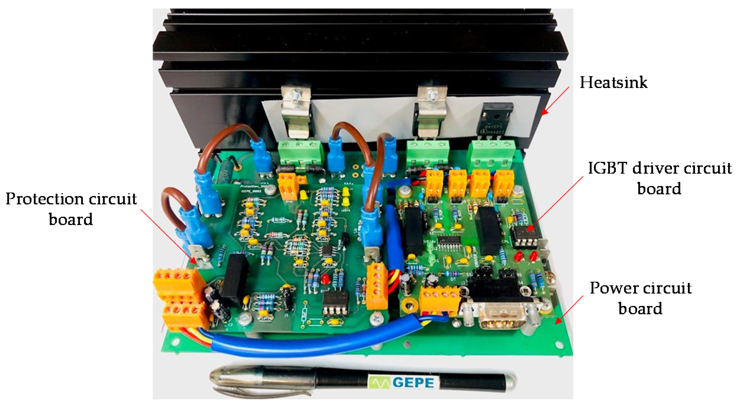
3.3.4. Final Modular Multilevel Converter Submodule

Figure 11 presents the final power submodule (SM) structure, including the driver circuit board, the protection circuit board, the power circuit board and the IGBT heatsink. It is worth noting that the final SM hardware has a compact, extensible, and cubic design to build the reduced-scale RPC based on half-bridge MMC prototype. Each four cascade-connected SMs are composed of a single MMC leg/phase, as shown in Figure 12. The total number of SMs for the RPC based on half-bridge MMC reduced-scale prototype is eight. Section 4 presents the experimental analysis of the reduced-scale prototype RPC based on half-bridge MMC under two case studies: (a) when two load sections are loaded; and (b) when only one load section is loaded. Then, a discussion of experimental results of a reduced-scale prototype is provided to link with the performance of the RPC based on MMC under high-power applications.

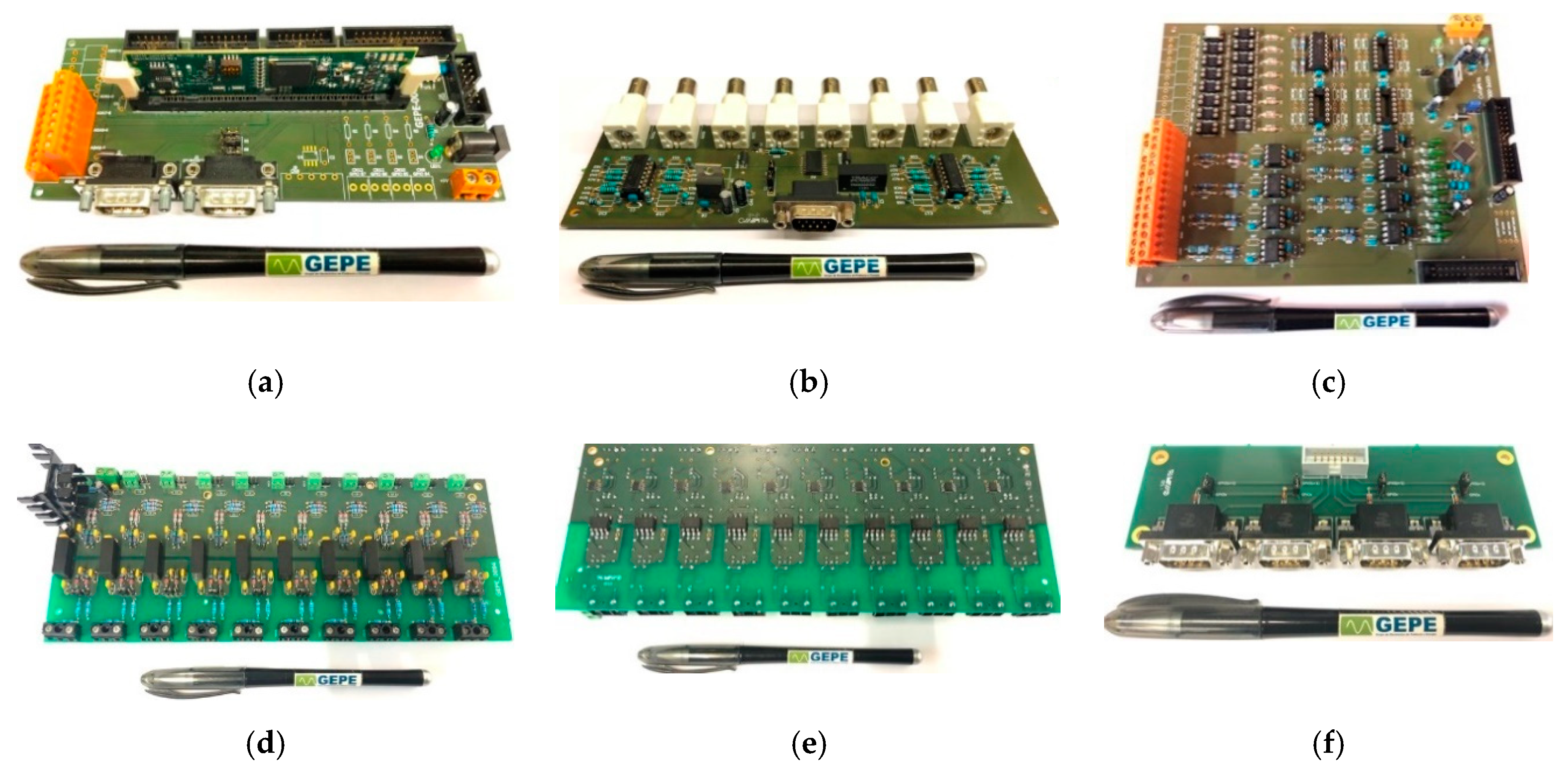
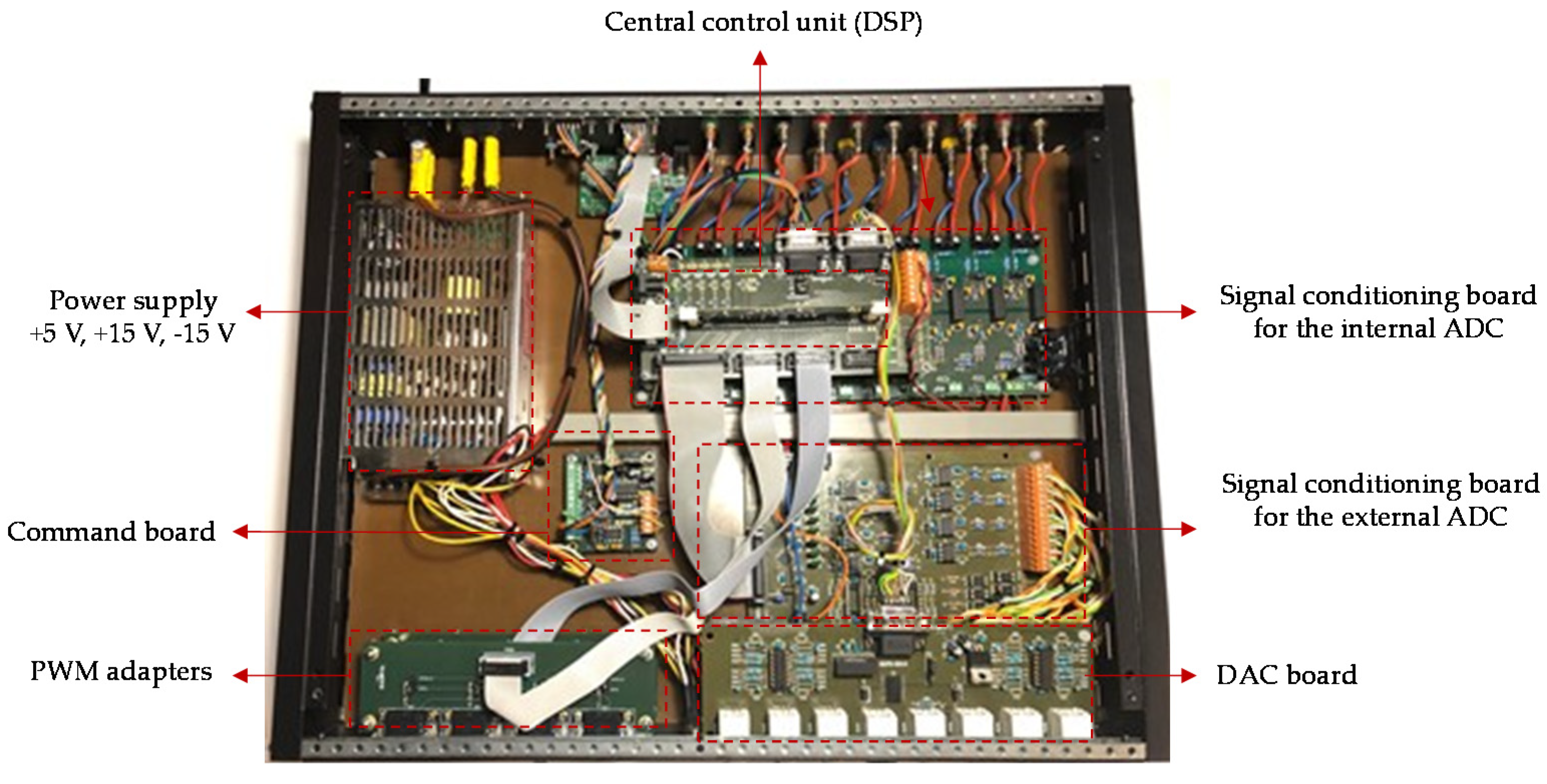
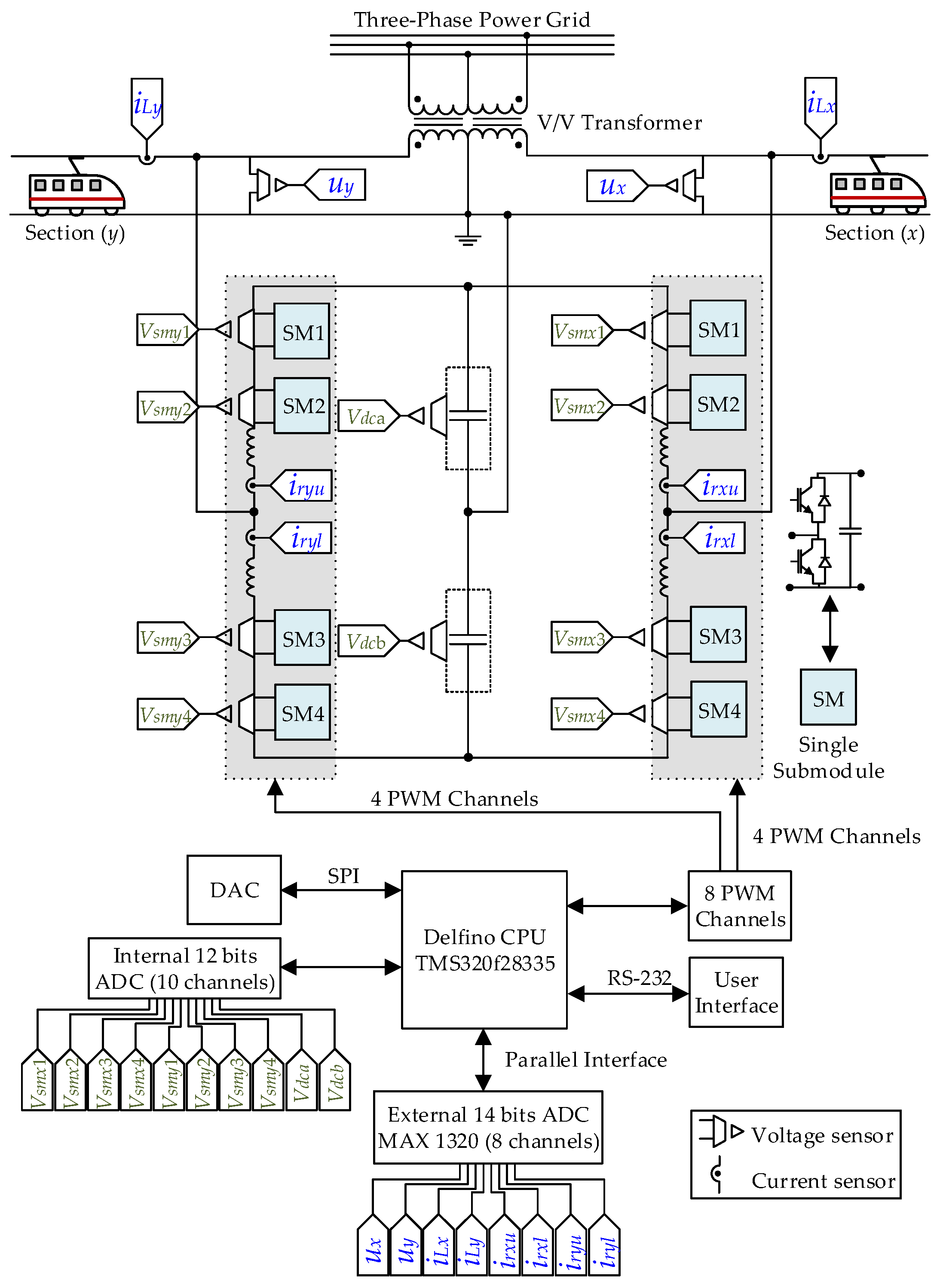
3.4. Control System Hardware

The control system hardware has several output flat cable connectors to link between the digital signal processor (DSP) and the auxiliary control units, such as sensors and actuators. The digital system loop always exchanges information between the DSP and the auxiliary control units (such as signal conditioning unit, sensors unit, and the PWM control unit). The DSP board is presented in Figure 13a, and integrates several connectors to facilitate the connection between different control boards and the DSP control unit. Figure 13b presents a digital-to-analogue converter (DAC) board, which is important to verify the accuracy of the digital signals generated in the DSP. Two signal conditioning boards are used; the one presented in Figure 13c is dedicated to the external analogue-to-digital converter (ADC) channels, and the other presented in Figure 13d,e is dedicated to the internal ADC channels in the DSP. This ADC board contains two main parts: the voltage sensors placed at the bottom side, and the signal conditioning part placed at the top side. PWM adapters are used to convert from ribbon cable terminals to DB-9 connector terminals, as presented in Figure 13f.
The control system hardware is enclosed in a metallic box, as shown in Figure 14. The metallic box also includes several input/output connectors to interface between the control system and the power system hardware, such as the driver circuit and the protection circuit boards. A command circuit board is used to interface and isolate between the driver circuit boards and the protection circuit boards. This command board also saves the error when an overcurrent or overvoltage condition is detected, stopping the IGBT switching devices, until a reset command is released. In addition, several power connectors in the metallic box are used to connect the SM DC-link voltages with the associated voltage sensors. A DC power supply is also used to convert the 230 V AC to a regulated low-voltage (+15 V, +5 V, −15 V) to supply the electronic components of the control system hardware. It is worth noting that the majority of the control system hardware is installed in the metallic box. This is very important to maintain the distance between the control system hardware and the power system hardware, thus reducing the electromagnetic interference effects. The electromagnetic fields generated due to the power system hardware can affect the correct functionality of the DSP, where these fields may induce currents loops in the electronic components.
Figure 15 shows the global communication structure of the reduced-scale RPC based on half-bridge MMC prototype. A depicted hardware architecture of the control system is presented, where a Delfino DSP controller from Texas Instruments TMS320f28335 is used as a central control unit [46]. The converter requires 18 ADC channels (12 voltage sensors and six current sensors), a DAC unit to check the correctness of digital signals in the DSP, and eight PWM channels (one PWM channel is used for each SM, then the driver circuit board generates two complementary PWM signals to derive the IGBT switching devices). A user interface unit based on the RS-232 data interface is used to send and receive commands, such as commands for pre-charging and discharging of SM capacitors. Two ADC units are used to convert the analogue signals to digital signals. Subsequently, the digital signals can be analyzed and processed by the DSP. However, the ADC units have different bit resolutions; the internal ADC channels of the DSP are unipolar and have 12 bits of resolution. Therefore, they are dedicated to the purpose of DC signal processing, such as the MMC DC-link voltages (SM voltages and main DC-link voltage). The external ADC integrated circuit (IC) has 8 bipolar ADC channels with 14 bits of resolution. Therefore, they are reserved for the purpose of AC signal processing, such as the load section voltages waveforms, as shown in Figure 15.

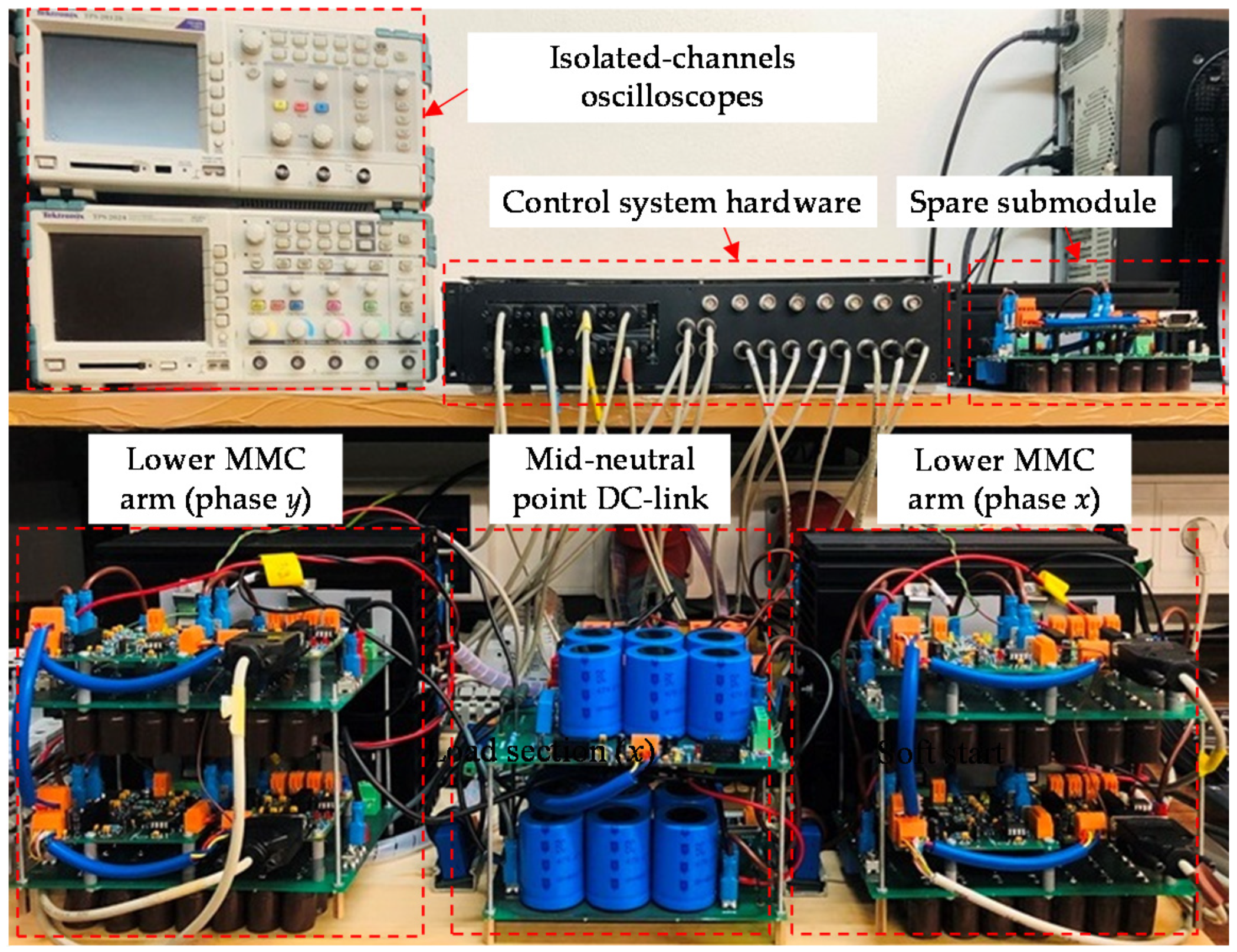
4. Experimental Results of the Laboratory Prototype RPC Based on Half-Bridge MMC

This section presents the RPC based on half-bridge MMC experimental results. Figure 16 shows the implemented MMC workbench, which includes the control system hardware, isolated-channel oscilloscopes, and a spare SM. A computer device is used that allows user interface with the DSP. The experimental results were obtained using the TPS2000B oscilloscope from Tektronix. In addition, a Fluke 434 Power Quality Analyzer was used to measure the THD, the ratio of NSC, and the frequency spectrum of the three-phase currents. Figure 17 shows the experimental setup schematic, which consists of the supplementary power equipment (auto-transformers, V/V transformer, and full-bridge rectifiers) and the RPC based on half-bridge MMC. For this purpose, full-bridge rectifiers with filtering capacitors are used to create harmonic contents and current imbalance in the three-phase public power grid. The parameters used in this experimental validation are presented in Table 2, where load section y active power is selected to be 150% of the active power of the load section x. Therefore, as presented in Table 2, the value of the resistor Rx1 is 150% the value of the resistor Ry1.
The resistors of Rx2 and Ry2 have a high value because their main function is to discharge the filtering capacitors after disconnecting the load power resistors, Rx1 and Ry1, using contactors. The reduced-scale RPC based on half-bridge MMC consists of eight half-bridge SMs, in which each MMC leg or phase has four SMs. The MMC parameters, such as capacitance of the SM capacitor, the capacitance of the main DC-link capacitor, the MMC leg filter inductors, and the PWM switching frequency, are also presented in Table 2. Two case studies are presented in this experimental test: The first case study is when the load section y active power is 150% of the load section x active power, and the second case study is when only load section y is loaded.

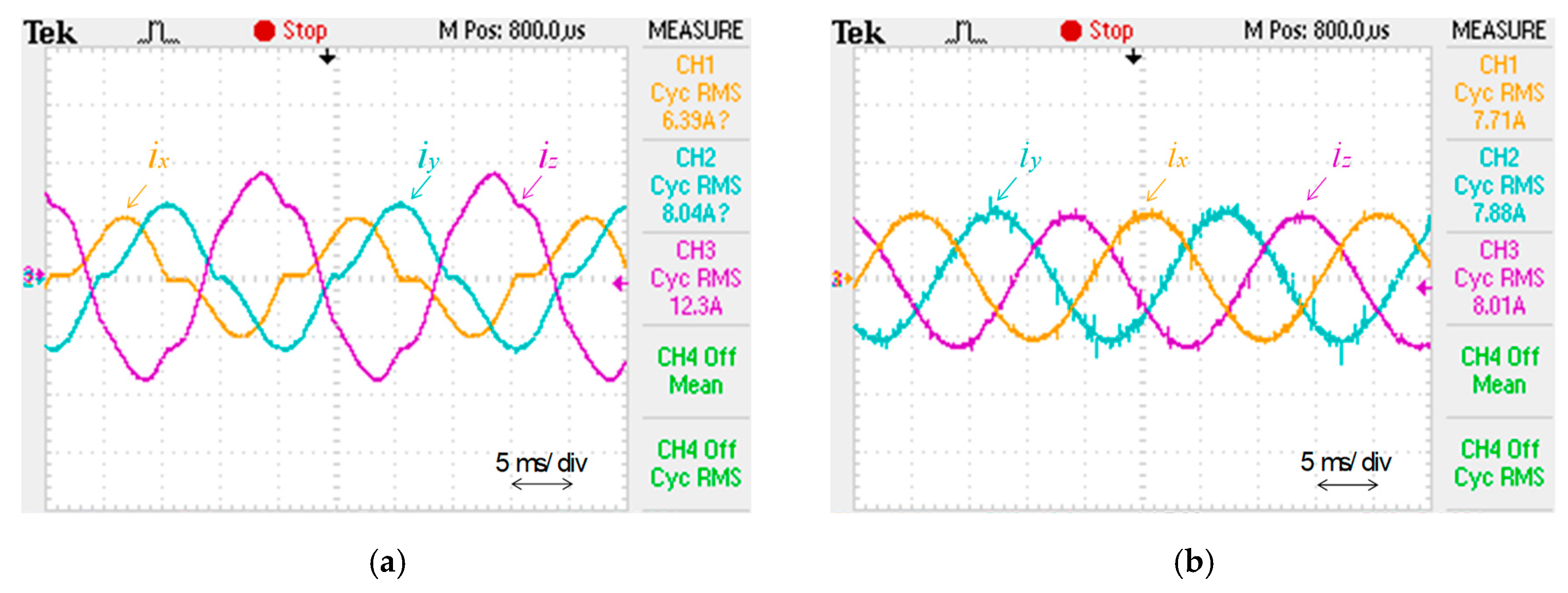
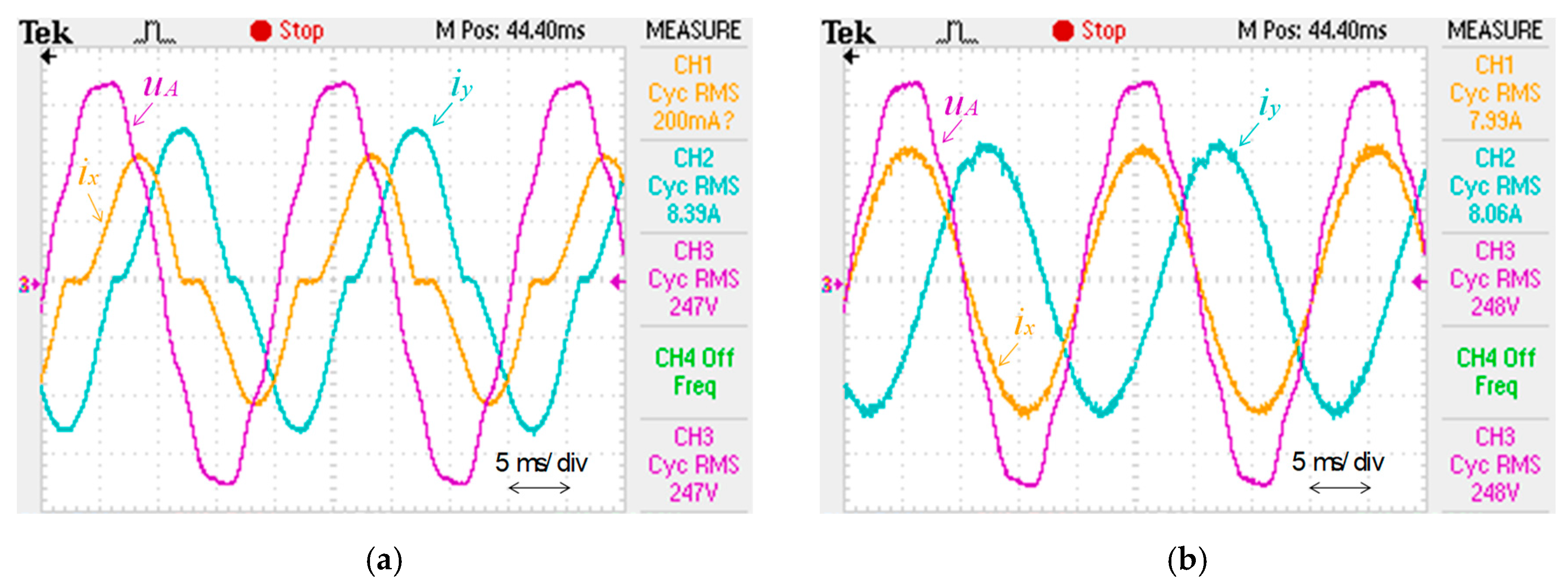
4.1. Experimental Results When Two Load Sections are Loaded

This item presents the RPC based on half-bridge MMC prototype experimental results when the load section y active power is 150% of the active power of the load section x. Figure 18a shows the three-phase currents at the secondary windings of the V/V transformer before compensation, and when both load sections are unequally loaded. The currents are imbalanced and contain harmonic content. Figure 19a shows the phase difference angle between the phase x and phase y currents or the load section currents before compensation and the phase-to-neutral voltage uA, which is used as a reference waveform with a phase angle equal to zero. There are almost 30° out-of-phase between uA and ix, and nearly 90° out-of-phase between uA and iy before compensation.
Figure 18b presents the three-phase currents at the secondary windings of the V/V transformer after compensation. The currents are balanced with lower harmonic content and without NSCs. In this case, the RPC compensates reactive power and balances the active power between the load sections. Consequently, a unitary power factor is obtained at the three-phase power grid. In addition, there are almost 0° out-of-phase between uA and ix, and almost 120°out-of-phase between uA and iy after compensation, as presented in Figure 19b. This means the reactive power is totally exchanged between the load sections and the power compensator. There is no reactive power exchanged with the three-phase power grid and the power factor is unitary.
Figure 20 presents the frequency spectrum of the three-phase currents at the secondary windings of the V/V transformer. Figure 20a shows the harmonic contents before compensation with a THD ratio close to 23.1%. Figure 20b shows the harmonic contents after compensation with a THD ratio close to 3.1%. These results are obtained at a fundamental frequency component of 50 Hz.
Figure 21a presents the values of the harmonic contents before compensation. Phase x current ix has the highest ratio of THD, with a value close to 22.9%. The third-order harmonic is the highest harmonic content before compensation. Figure 21b shows the values of the harmonic contents after compensation. In this case, the THD ratio is significantly reduced, particularly the third- and fifth-order harmonics. It is worth noting that the even-order harmonics circulate between the MMC phases and do not contribute to the RPC compensation currents.
Figure 22 shows the phasors diagram and the unbalance ratio (NSC ratio) of the three-phase currents at the secondary of the V/V transformer. The unbalance ratio before compensation is close to 46.8%, as shown in Figure 22a. The phasors diagram, in this case, shows three-phase current vectors that have different magnitude values. By considering the phase voltage uA as a reference and due to the nature of the V/V connection, the phase x current lags the reference voltage by nearly 30°, whereas the phase y current lags the reference voltage by nearly 90°. Figure 22b shows the unbalance ratio and the phasors diagram of the three-phase currents after compensation. The unbalance ratio, in this case, is significantly reduced and has a value close to 2.9%. As observed, the three-phase current phasors are balanced, with similar magnitude values and 120° out-of-phase.
The compensation currents synthesized by the RPC are presented in Figure 23. The compensation current of the load section x, irx, is higher than the compensation current of the load section y, iry. This is due to the unequal loading power and the fact that the section x converter injects a higher amount of energy than the section y converter. In a V/V connection, the section x converter compensates a quantity of a capacitive reactive power, whereas the section y converter compensates a quantity of an inductive reactive power.
Figure 24a,b shows the SM voltage waveforms of the section x converter and the section y converter, respectively. The SM voltages are close to the reference value of 80 V. However, due to the half-bridge topology of the SM, the voltage ripple frequency is equal to the fundamental frequency of 50 Hz. Furthermore, because the section x converter injects a higher amount of power, the SM voltages of section x converter VSMx1, VSMx2, VSMx3, and VSMx4, have higher voltage ripples than the SM voltages of section y converter VSMy1, VSMy2, VSMy3, and VSMy4. These results confirm the effectiveness of the MMC leg averaging voltage balancing control and the MMC SM individual voltage balancing control to maintain a balanced voltage of the MMC SMs.

4.2. Experimental Results When One Load Section is Loaded

This item presents the RPC based on half-bridge MMC prototype experimental results when only the load section y is loaded (load section x has no loads). Figure 25a shows the secondary windings three-phase currents of the V/V transformer before compensation, and when only load section y is loaded. The currents are imbalanced and contain harmonic contents. Phase x current ix, has a zero RMS value because the load section x is not loaded. Consequently, phase y current iy and phase z current iz, have 180° out-of-phase. The imbalance ratio, in this case, is higher than the case when both of the load sections were loaded. Figure 25b presents the secondary windings three-phase currents of the V/V transformer after compensation. The currents are balanced with lower harmonic contents and lower NSCs of currents. In this case, the RPC compensates reactive power and balances the active power between the load sections, thus a unitary power factor is obtained at the three-phase power grid side.
Figure 26 presents the frequency spectrum of the three-phase currents at the secondary windings of the V/V transformer. In this context, Figure 26a shows the harmonic contents before compensation with a THD ratio close to 15.1% at a fundamental frequency of 50 Hz. Figure 26b shows the harmonic contents after the compensation with a THD ratio close to 2.5%. This confirms the effectiveness of the RPC based on half-bridge MMC system in improving the power quality of the three-phase power grid
Figure 27a presents the values of harmonic contents before compensation. Phase y and phase z currents have 180° out-of-phase, and have almost the same ratio of the THD. The third-order harmonic is the highest harmonic content before compensation, with a ratio close to 14.2%, considering a fundamental frequency of 50 Hz. Figure 27b shows the values of the harmonic contents after compensation. In this case, the THD is significantly reduced, and the third-order harmonics does not exceed the ratio of 2%. It is worth noting that the even-order harmonics circulate between the MMC phases and do not contribute to the RPC compensation currents.
Figure 28 shows the phasors diagram and the unbalance ratio of the three-phase currents at the secondary windings of the V/V transformer. The unbalance ratio (NSC ratio) before compensation is close to 97.7%, as shown in Figure 28a. The phasors diagram, in this case, shows only two-phase currents that have equal magnitudes and 180° out-of-phase. By considering the phasor of the phase voltage uA as a reference, due to the nature of the V/V connection, phase y current lags the reference by nearly 90°, whereas phase z current lags the reference by nearly 270°. Figure 28b shows the unbalance ratio and the phasors diagram of the three-phase currents after compensation. The unbalance ratio, in this case, is significantly reduced and has a value close to 1.6%. As observed, the three-phase current phasors are balanced, with similar magnitude values and 120° out-of-phase.
The compensation currents synthesized by the RPC are presented in Figure 29. The compensation current of the load section x, irx, is completely sinusoidal because there are no loads connected to the load section x. In this case, the section x converter compensates the reactive power and balances the active power between the load sections. The section y converter compensates harmonic contents and reactive power, and also balances the active power between the load sections.
Figure 30a,b shows the SM voltage waveforms of the section x converter and the section y converter, respectively. The SM voltages are close to the reference value of 80 V. However, due to the half-bridge topology of the SM, the voltage ripple frequency is equal to the fundamental frequency of 50 Hz. Furthermore, because the section x converter and the section y converter compensate an almost equal amount of power, the SM voltages of the MMC have almost equal voltage ripples for the section x and section y converters. These results confirm the effectiveness of the MMC leg averaging voltage balancing control and the MMC SM individual voltage balancing control to maintain a balanced voltage of the MMC SMs.

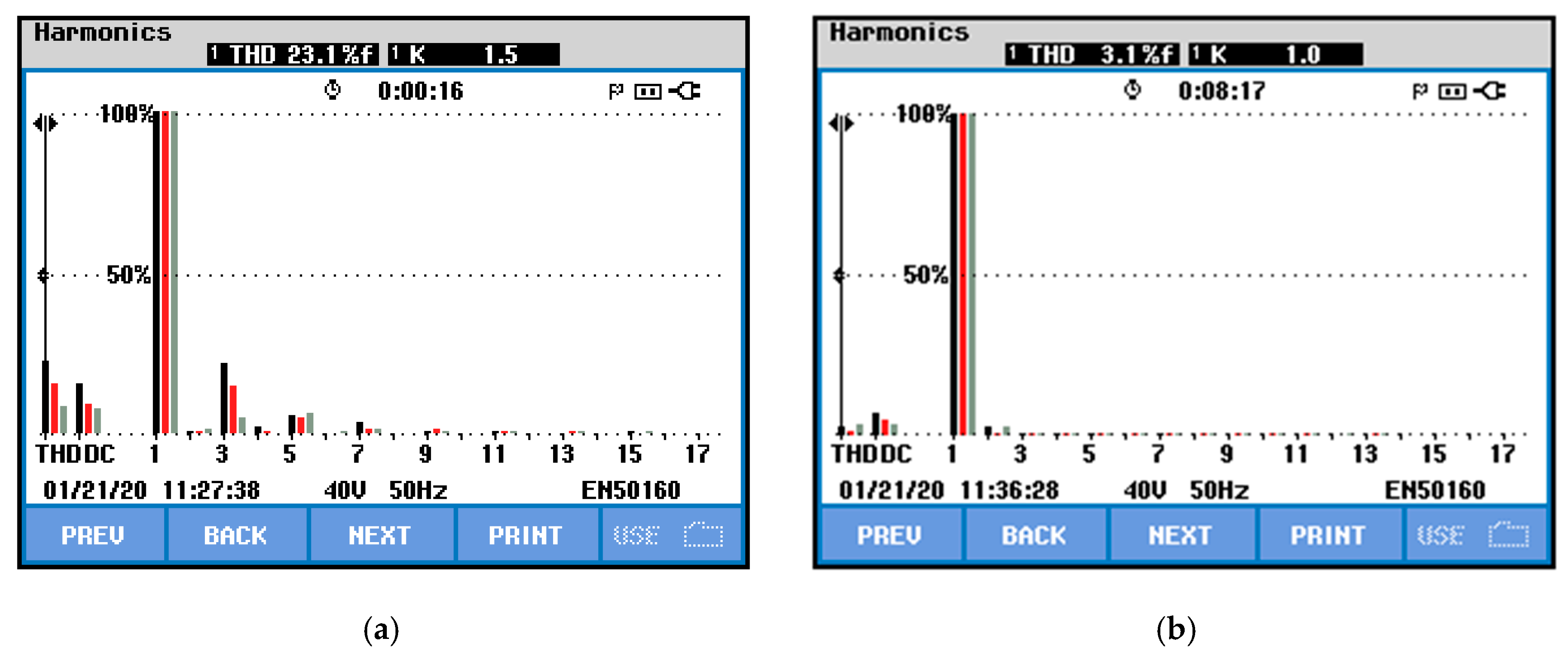
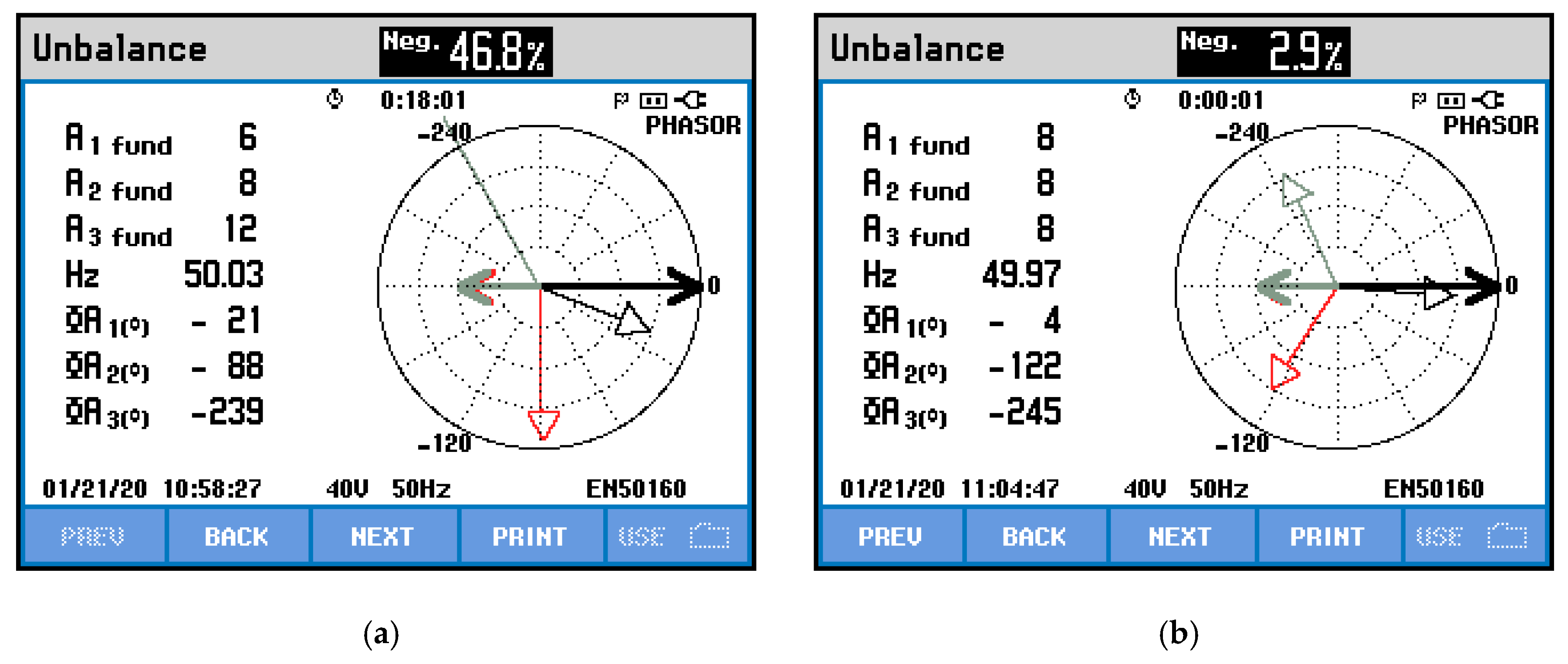
4.3. Discussion and Experimental Analysis

The presented experimental results confirm the validity of the compensation strategy and the associated capacitor voltage balancing control of the MMC SMs presented in this paper. In addition, the experimental results show that the RPC based on half-bridge MMC is a viable solution for the purpose of power quality improvement in electrified railway systems. In the experimental validation, only eight SMs with a 40 kHz switching frequency were used. However, for high-power applications, a few tens of SMs with a lower SM switching frequency should be employed, which and would allow the MMC to synthesize sinusoidal waveforms with better quality and lower harmonic contents. Subsequently, the experimental case reported in this paper involves a low number of SMs with a high SM switching frequency (this choice was selected to reduce the MMC complexity and costs). It was verified that the compensation currents synthesized by the reduced-scale RPC based on half-bridge MMC satisfy the requirements of NSC compensation and harmonics cancelation. As a result, it is important to highlight that, in high-power applications, the number of MMC SMs should increase, but the switching frequency could be reduced to achieve the same objectives.

5. Conclusions

This paper presented the implementation, testing, and experimental validation of a reduced-scale laboratory prototype of a proposed rail power conditioner (RPC) based on a modular multilevel converter (MMC). The design of the parameters of the MMC, such as filter inductors and submodule (SM) capacitors, were also described in the paper. Moreover, SM power components and the associated power hardware were explained in detail. This power hardware involved three main circuit boards: the driver circuit board, protection circuit board, and power circuit board. Furthermore, the control system hardware of the reduced-scale RPC based on MMC was introduced in the paper, in addition to the related communication structure between the MMC power and control circuit boards.
Experimental results were presented considering two case studies of electrified railway systems: when both load sections (x and y) are loaded and when only the load section y is loaded. In the first case study, the load section y active power is 150% of the active power of the load section x, whereas, in the second case study, the load section x has no load and the load section y maintains its power value. Experimental results show that the RPC based on half-bridge MMC system injects a higher amount of reactive power and shifts a higher amount of active power in the second case study, which is the worst-case scenario. In this case, the compensation currents synthesized by the RPC are higher than those presented in the first case study.
In this developed prototype, only eight SMs with high switching frequency are used, to reduce the MMC complexity. The switching frequency is 40 kHz, which allows sinusoidal current waveforms to be synthesized with very good quality, and also permits a fast dynamic response to be obtained. However, in high-power applications, a few tens of SMs with low switching frequency should be used to achieve the same objectives. This will lead to higher scalability and reliability of the MMC in high power applications. Thus, if one SM breaks, it will not fully affect the MMC functionality. The higher the number of SMs, the better the quality and robustness of the generated waveforms. Consequently, increasing the total number of SMs is a relevant suggestion for future work. The presented experimental analysis proves the effectiveness of the proposed RPC based on MMC and its principle of operation, thus improving the power quality in electrified railway power grids.

Author Contributions

M.T., J.C. and L.A.M.B.: performed the analysis, design, testing and validating of the reduced-scale laboratory prototype explained in this paper. M.T.: involves in the writing—original draft preparation. All authors participated in the conceptualization, methodology, and writing—review and editing. All authors have read and agreed to the published version of the manuscript.

Funding

This work has been supported by the Portuguese Foundation of Science and Technology (FCT), in Portuguese, Fundação para a Ciência e Tecnologia within the R&D Units Project Scope: UIDB/00319/2020. Mohamed Tanta was supported by FCT grant with a reference PD/BD/127815/2016. Jose Cunha is supported by FCT grant with a reference PB/BD/143005/2018. Luis A. M. Barros is supported by FCT grant with a reference PD/BD/143006/2018.

Institutional Review Board Statement

Not applicable.

Informed Consent Statement

Not applicable.

Data Availability Statement

Not applicable.

Conflicts of Interest

The authors declare no conflict of interest.

References

  1. Farnesi, S.; Marchesoni, M.; Vaccaro, L. Advances in Locomotive Power Electronic Systems Directly Fed through AC Lines. In Proceedings of the 2016 International Symposium on Power Electronics, Electrical Drives, Automation and Motion (SPEEDAM), Anacapri, Italy, 22–24 June 2016; pp. 657–664. [Google Scholar]
  2. Nesterov, N.; Bykov, A. Locomotive Noise Reduction. In MATEC Web of Conferences; EDP Sciences: Moscow, Russia, 2020; Volume 320, p. 00013. [Google Scholar]
  3. Perin, I.; Nussey, P.F.; Cella, U.M.; Tran, T.V.; Walker, G.R. Application of Power Electronics in Improving Power Quality and Supply Efficiency of AC Traction Networks. In Proceedings of the 2015 IEEE 11th International Conference on Power Electronics and Drive Systems, Sydney, Australia, 9–12 June 2015; pp. 1086–1094. [Google Scholar]
  4. He, Z.; Zheng, Z.; Hu, H. Power Quality in High-Speed Railway Systems. Int. J. Rail Transp. 2016, 4, 71–97. [Google Scholar] [CrossRef] [Green Version]
  5. Langerudy, A.T.; Mariscotti, A.; Abolhassani, M.A. Power Quality Conditioning in Railway Electrification: A Comparative Study. IEEE Trans. Veh. Technol. 2017, 66, 6653–6662. [Google Scholar] [CrossRef]
  6. Morais, V.A.; Afonso, J.L.; Carvalho, A.S.; Martins, A.P. New Reactive Power Compensation Strategies for Railway Infrastructure Capacity Increasing. Energies 2020, 13, 4379. [Google Scholar] [CrossRef]
  7. Gazafrudi, S.M.M.; Langerudy, A.T.; Fuchs, E.F.; Al-Haddad, K. Power Quality Issues in Railway Electrification: A Comprehensive Perspective. IEEE Trans. Ind. Electron. 2015, 62, 3081–3090. [Google Scholar] [CrossRef]
  8. Luo, A.; Wu, C.; Shen, J.; Shuai, Z.; Ma, F. Railway Static Power Conditioners for High-Speed Train Traction Power Supply Systems Using Three-Phase V/V Transformers. IEEE Trans. Power Electron. 2011, 26, 2844–2856. [Google Scholar] [CrossRef]
  9. Oso, H.; Kaneko, T.; Suzuki, A. Railway Static Power Conditioner for Shin-Kurobe Substation of Hokuriku Shinkansen. Fuji Electr. Rev. 2015, 61, 52–57. [Google Scholar]
  10. Tanta, M.; Pinto, G.; Monteiro, V.; Martins, A.P.; Carvalho, A.S.; Afonso, J.L. A Comprehensive Comparison of Rail Power Conditioners Based on Two-Level Converters and a V/V Power Transformer in Railway Traction Power Systems. In Proceedings of the 7th Transport Research Arena (TRA 2018), Vienna, Austria, 16–19 April 2018; pp. 1–10. [Google Scholar]
  11. Langerudy, A.T.; Mariscotti, A. Tuning of a Railway Power Quality Conditioner. In Proceedings of the 2016 18th Mediterranean Electrotechnical Conference (MELECON), Lemesos, Cyprus, 18–20 April 2016; pp. 1–7. [Google Scholar]
  12. Serrano-Jiménez, D.; Abrahamsson, L.; Castaño-Solís, S.; Sanz-Feito, J. Electrical Railway Power Supply Systems: Current Situation and Future Trends. Int. J. Electr. Power Energy Syst. 2017, 92, 181–192. [Google Scholar] [CrossRef]
  13. Afonso, J.L.; Cardoso, L.A.L.; Pedrosa, D.; Sousa, T.J.C.; Machado, L.; Tanta, M.; Monteiro, V. A Review on Power Electronics Technologies for Electric Mobility. Energies 2020, 13, 6343. [Google Scholar] [CrossRef]
  14. Tanta, M.; Barros, L.A.M.; Pinto, G.; Martins, A.P.; Afonso, J.L. Modular Multilevel Converter in Electrified Railway Systems: Applications of Rail Static Frequency Converters and Rail Power Conditioners. In Proceedings of the 2020 International Young Engineers Forum (YEF ECE), Costa da Caparica, Portugal, 3 July 2020; pp. 1–6. [Google Scholar]
  15. Kouro, S.; Malinowski, M.; Gopakumar, K.; Pou, J.; Franquelo, L.G.; Wu, B.; Rodriguez, J.; Pérez, M.A.; Leon, J.I. Recent Advances and Industrial Applications of Multilevel Converters. IEEE Trans. Ind. Electron. 2010, 57, 2553–2580. [Google Scholar] [CrossRef]
  16. Debnath, S.; Qin, J.; Bahrani, B.; Saeedifard, M.; Barbosa, P. Operation, Control, and Applications of the Modular Multilevel Converter: A Review. IEEE Trans. Power Electron. 2015, 30, 37–53. [Google Scholar] [CrossRef]
  17. Knaak, H.J. Modular Multilevel Converters and HVDC/FACTS: A Success Story. In Proceedings of the 2011 14th European Conference on Power Electronics and Applications, Birmingham, UK, 30 August–1 September 2011; pp. 1–6. [Google Scholar]
  18. Ronanki, D.; Williamson, S.S. Modular Multilevel Converters for Transportation Electrification: Challenges and Opportunities. IEEE Trans. Transp. Electrif. 2018, 4, 399–407. [Google Scholar] [CrossRef]
  19. Barros, L.A.M.; Tanta, M.; Martins, A.P.; Afonso, J.L.; Pinto, J.G. Opportunities and Challenges of Power Electronics Systems in Future Railway Electrification. In Proceedings of the 2020 IEEE 14th International Conference on Compatibility, Power Electronics and Power Engineering (CPE-POWERENG), Setubal, Portugal, 8–10 July 2020; Volume 1, pp. 530–537. [Google Scholar]
  20. Mohammadi, P.H.; Bina, M.T. A Transformerless Medium-Voltage STATCOM Topology Based on Extended Modular Multilevel Converters. IEEE Trans. Power Electron. 2011, 26, 1534–1545. [Google Scholar] [CrossRef]
  21. Feng, J.; Chu, W.Q.; Zhang, Z.; Zhu, Z.Q. Power Electronic Transformer-Based Railway Traction Systems: Challenges and Opportunities. IEEE J. Emerg. Sel. Top. Power Electron. 2017, 5, 1237–1253. [Google Scholar] [CrossRef]
  22. Xu, Q.; Ma, F.; He, Z.; Chen, Y.; Guerrero, J.M.; Luo, A.; Li, Y.; Yue, Y. Analysis and Comparison of Modular Railway Power Conditioner for High-Speed Railway Traction System. IEEE Trans. Power Electron. 2016, 32, 6031–6048. [Google Scholar] [CrossRef] [Green Version]
  23. Tanta, M.; Pinto, G.; Monteiro, V.; Martins, A.P.; Carvalho, A.S.; Afonso, J.L. Cost Estimation of Rail Power Conditioner Topologies Based on Indirect Modular Multilevel Converter in V/V and Scott Power Transformers. In Proceedings of the 4th International Conference on Energy and Environment: Bringing together Engineering and Economics, Guimarães, Portugal, 16 May 2019; pp. 365–370. [Google Scholar]
  24. Qin, F.; Hao, T.; Gao, F. A Railway Power Conditioner Using Direct AC-AC Modular Multilevel Converter. In Proceedings of the 2019 2nd International Conference on Smart Grid and Renewable Energy (SGRE), Doha, Qatar, 19–21 November 2019; pp. 1–5. [Google Scholar]
  25. Ma, F.; He, Z.; Xu, Q.; Luo, A.; Zhou, L.; Li, M. Multilevel Power Conditioner and Its Model Predictive Control for Railway Traction System. IEEE Trans. Ind. Electron. 2016, 63, 7275–7285. [Google Scholar] [CrossRef]
  26. Tanta, M.; Pinto, J.G.; Monteiro, V.; Martins, A.P.; Carvalho, A.S.; Afonso, J.L. Topologies and Operation Modes of Rail Power Conditioners in AC Traction Grids: Review and Comprehensive Comparison. Energies 2020, 13, 2151. [Google Scholar] [CrossRef]
  27. Lu, M.; Hu, J.; Zeng, R.; He, Z. Fundamental-Frequency Reactive Circulating Current Injection for Capacitor Voltage Balancing in Hybrid-MMC HVDC Systems During Riding Through PTG Faults. IEEE Trans. Power Deliv. 2018, 33, 1348–1357. [Google Scholar] [CrossRef]
  28. Krastev, I.; Tricoli, P.; Hillmansen, S.; Chen, M. Future of Electric Railways: Advanced Electrification Systems with Static Converters for AC Railways. IEEE Electrif. Mag. 2016, 4, 6–14. [Google Scholar] [CrossRef]
  29. He, X.; Peng, J.; Han, P.; Liu, Z.; Gao, S.; Wang, P. A Novel Advanced Traction Power Supply System Based on Modular Multilevel Converter. IEEE Access 2019, 7, 165018–165028. [Google Scholar] [CrossRef]
  30. Perez, M.A.; Bernet, S.; Rodriguez, J.; Kouro, S.; Lizana, R. Circuit Topologies, Modeling, Control Schemes, and Applications of Modular Multilevel Converters. IEEE Trans. Power Electron. 2015, 30, 4–17. [Google Scholar] [CrossRef]
  31. Tanta, M.; Pinto, J.G.; Monteiro, V.; Martins, A.P.; Carvalho, A.S.; Afonso, J.L. Deadbeat Predictive Current Control for Circulating Currents Reduction in a Modular Multilevel Converter Based Rail Power Conditioner. Appl. Sci. 2020, 10, 1849. [Google Scholar] [CrossRef] [Green Version]
  32. Tanta, M.; Monteiro, V.; Exposto, B.; Pinto, J.G.; Martins, A.P.; Carvalho, A.S.; Meléndez, A.A.N.; Afonso, J.L. Simplified Rail Power Conditioner Based on a Half-Bridge Indirect AC/DC/AC Modular Multilevel Converter and a V/V Power Transformer. In Proceedings of the IECON 2017—43rd Annual Conference of the IEEE Industrial Electronics Society, Beijing, China, 29 October–1 November 2017; pp. 6431–6436. [Google Scholar]
  33. Hagiwara, M.; Akagi, H. Control and Experiment of Pulsewidth-Modulated Modular Multilevel Converters. IEEE Trans. Power Electron. 2009, 24, 1737–1746. [Google Scholar] [CrossRef]
  34. Karimi-Ghartemani, M. Linear and Pseudolinear Enhanced Phased-Locked Loop (EPLL) Structures. IEEE Trans. Ind. Electron. 2014, 61, 1464–1474. [Google Scholar] [CrossRef]
  35. Ma, F.; Luo, A.; Xu, X.; Xiao, H.; Wu, C.; Wang, W. A Simplified Power Conditioner Based on Half-Bridge Converter for High-Speed Railway System. IEEE Trans. Ind. Electron. 2013, 60, 728–738. [Google Scholar] [CrossRef]
  36. Dai, N.; Wong, M. Design Considerations of Coupling Inductance for Active Power Filters. In Proceedings of the 2011 6th IEEE Conference on Industrial Electronics and Applications, Beijing, China, 21–23 June 2011; pp. 1370–1375. [Google Scholar]
  37. Tu, Q.; Xu, Z.; Huang, H.; Zhang, J. Parameter Design Principle of the Arm Inductor in Modular Multilevel Converter Based HVDC. In Proceedings of the 2010 International Conference on Power System Technology, Hangzhou, China, 24–28 October 2010; pp. 1–6. [Google Scholar]
  38. Harnefors, L.; Antonopoulos, A.; Norrga, S.; Angquist, L.; Nee, H. Dynamic Analysis of Modular Multilevel Converters. IEEE Trans. Ind. Electron. 2013, 60, 2526–2537. [Google Scholar] [CrossRef]
  39. Liu, L.; Dai, N. Hybrid Railway Power Conditioner Based on Half-Bridge Modular Multilevel Converter. In Proceedings of the 2016 IEEE Energy Conversion Congress and Exposition (ECCE), Milwaukee, WI, USA, 18–22 September 2016; pp. 1–7. [Google Scholar]
  40. Sharifabadi, K.; Harnefors, L.; Nee, H.-P.; Norrga, S.; Teodorescu, R. Design, Control and Application of Modular Multilevel Converters for HVDC Transmission Systems; Wiley-IEEE Press: Hoboken, NJ, USA, 2016; ISBN 978-1-118-85156-2. [Google Scholar]
  41. Barros, L.A.M.; Tanta, M.; Martins, A.P.; Afonso, J.L.; Pinto, J.G. STATCOM Evaluation in Electrified Railway Using V/V and Scott Power Transformers. In Proceedings of the Sustainable Energy for Smart Cities, SESC 2019, Braga, Portugal, 4–6 December 2019; Afonso, J.L., Monteiro, V., Pinto, J.G., Eds.; Springer International Publishing: Cham, Switzerland, 2020; pp. 18–32. [Google Scholar]
  42. Silicon Labs Si824x—Class D Audio Driver with Precision Dead-Time Generator. Available online: https://www.silabs.com/documents/public/data-sheets/Si824x.pdf (accessed on 9 October 2018).
  43. Tanta, M.; Cunha, J.; Monteiro, V.; Martins, A.P.; Carvalho, A.S.; Afonso, J.L. A Novel Hardware Protection Scheme for a Modular Multilevel Converter Half-Bridge Submodule. In Proceedings of the IECON 2019—45th Annual Conference of the IEEE Industrial Electronics Society, Lisbon, Portugal, 14–17 October 2019; Volume 1, pp. 6043–6048. [Google Scholar]
  44. Wang, H.; Blaabjerg, F. Reliability of Capacitors for DC-Link Applications in Power Electronic Converters—An Overview. IEEE Trans. Ind. Appl. 2014, 50, 3569–3578. [Google Scholar] [CrossRef] [Green Version]
  45. Gruson, F.; Kadri, R.; Colas, F.; Guillaud, X.; Delarue, P.; Bergé, M.; Dennetiere, S.; Bachir, T.O. Design, Implementation and Testing of a Modular Multilevel Converter. EPE J. 2017, 27, 153–166. [Google Scholar] [CrossRef] [Green Version]
  46. Texas Instruments TMS320F2833x, TMS320F2823x Digital Signal Controllers (DSCs). Available online: http://www.ti.com/lit/ds/symlink/tms320f28335.pdf (accessed on 18 October 2018).
Figure 1. Typical rail power conditioner (RPC) connection with two-level back-to-back converters and open-delta (V/V) power transformer.
Energies 14 00484 g001
Figure 2. Rail power conditioner (RPC) topologies based on an AC/DC/AC modular multilevel converter (MMC) and V/V power transformer: (a) RPC based on full-bridge back-to-back MMC; (b) RPC based on two-phase three-wires MMC; (c) RPC based on half-bridge MMC.
Energies 14 00484 g002
Figure 3. Schematic of a half-bridge submodule (SM).
Energies 14 00484 g003
Figure 4. RPC based on half-bridge MMC and V/V power transformer control strategy.
Energies 14 00484 g004
Figure 5. RPC based on half-bridge MMC control blocks: (a) DC-link voltage control; (b) averaging voltage balancing control (AVBC); (c) individual voltage balancing control (IVBC).
Energies 14 00484 g005
Figure 6. Supplementary power equipment diagram.
Energies 14 00484 g006
Figure 7. Supplementary power equipment setup.
Energies 14 00484 g007
Figure 8. Isolated gate bipolar transistor (IGBT) driver circuit board.
Energies 14 00484 g008
Figure 9. Protection circuit board: (a) top view; (b) bottom view.
Energies 14 00484 g009
Figure 10. Power circuit board: (a) top view; (b) bottom view.
Energies 14 00484 g010
Figure 11. Final submodule (SM) structure.
Energies 14 00484 g011
Figure 12. Single MMC leg/phase (four submodules).
Energies 14 00484 g012
Figure 13. Some of the control system boards: (a) digital signal processor (DSP) board; (b) digital-to-analogue converter (DAC) board; (c) Signal conditioning board for the external analogue-to-digital converter (ADC); (d) Signal conditioning board for the internal ADC—top view; (e) Signal conditioning board for the internal ADC—bottom view; (f) pulse width modulation (PWM) adapter.
Energies 14 00484 g013
Figure 14. Control system hardware fitted in a metallic box.
Energies 14 00484 g014
Figure 15. Global communication structure of the reduced-scale prototype RPC based on half-bridge MMC.
Energies 14 00484 g015
Figure 16. Workbench with the developed modular multilevel converter (MMC).
Energies 14 00484 g016
Figure 17. Schematic of the RPC based on half-bridge MMC experimental setup.
Energies 14 00484 g017
Figure 18. Experimental results when two load sections are loaded: (a) before compensation; (b) after compensation. Phase x current (ix: 10 A/div); phase y current (iy: 10 A/div); phase z current (iz: 10 A/div).
Energies 14 00484 g018
Figure 19. Experimental results when two load sections are loaded: (a) before compensation; (b) after compensation. Phase x current (ix: 5 A/div); phase y current (iy: 5 A/div); phase A voltage (uA: 100 V/div).
Energies 14 00484 g019
Figure 20. Frequency spectrum of the three-phase currents at the secondary windings of the V/V transformer (when two load sections are loaded): (a) before compensation; (b) after compensation.
Energies 14 00484 g020
Figure 21. Harmonic contents value of the three-phase currents at the secondary windings of the V/V transformer (when two load sections are loaded): (a) before compensation; (b) after compensation.
Energies 14 00484 g021
Figure 22. Unbalance ratio and phasors diagram of three-phase currents at the secondary of the V/V transformer (when two load sections are loaded): (a) before compensation; (b) after compensation.
Energies 14 00484 g022
Figure 23. Experimental results (when two load sections are loaded): phase x compensation current (irx: 5 A/div); phase y compensation current (iry: 5 A/div).
Energies 14 00484 g023
Figure 24. Experimental results (when two load sections are loaded): (a) SM voltages of section x converter; (b) SM voltages of section y converter. SM DC voltage (VSM: 20 V/div).
Energies 14 00484 g024
Figure 25. Experimental results (one load section is loaded): (a) before compensation; (b) after compensation. Phase x current (ix: 5 A/div); phase y current (iy: 5 A/div); phase z current (iz: 5 A/div).
Energies 14 00484 g025
Figure 26. Frequency spectrum of the three-phase currents at the secondary windings of the V/V transformer (when one load section is loaded): (a) before compensation; (b) after compensation.
Energies 14 00484 g026
Figure 27. Harmonic contents value of the three-phase currents at the secondary windings of the V/V transformer (when one load section is loaded): (a) before compensation; (b) after compensation.
Energies 14 00484 g027
Figure 28. Unbalance ratio and phasors diagram of the three-phase currents at the secondary of the V/V transformer (when one load section is loaded): (a) before compensation; (b) after compensation.
Energies 14 00484 g028
Figure 29. Experimental results (when one load section is loaded): phase x compensation current (irx: 5 A/div); phase y compensation current (iry: 5 A/div).
Energies 14 00484 g029
Figure 30. Experimental results (when one load section is loaded): (a) SM voltages of section x converter; (b) SM voltages of section y converter. SM DC voltage (VSM: 20 V/div).
Energies 14 00484 g030
Table 1. Power circuit board components.
ComponentsSymbolsValues
Electrolytic capacitorCsm21 × 47 μF = 987 μF
Decoupling capacitorCde1.1 μF
Discharge resistorRdis5 kΩ
Table 2. Experimental parameters of the RPC based on half-bridge MMC.
ParametersSymbolsValues
Power grid RMS phase voltageuA, uB, uC230 V
Phase x and phase y RMS voltageux, uy40 V
SM voltageVSM80 V
MMC main DC-link voltageVdca + Vdcb160 V
Filter inductance of the armLxu, Lxl, Lyu, Lyl1.6 mH
Load section inductanceLx, Ly5 mH
Load resistor (section x)Rx16.5 Ω
Load resistor (section y)Ry14.34 Ω
Resistors to discharge the capacitorsRx2, Ry233 kΩ
Capacitance of the filtering capacitorsCx, Cy470 μF
Capacitance of the SM capacitorCSM987 µF
Capacitance of the main DC-link capacitorsCdca = Cdcb2820 µF
PWM SM switching frequencyfisw40 kHz
Modulating signal fundamental frequencyf50 Hz
Highest/Lowest duty-cycle0.92/0.08
Publisher’s Note: MDPI stays neutral with regard to jurisdictional claims in published maps and institutional affiliations.

