Review

Direct Utilization of Liquid Fuels in SOFC for Portable Applications: Challenges for the Selection of Alternative Anodes

by
Massimiliano Cimenti
and
Josephine M. Hill
*
Department of Chemical and Petroleum Engineering, Schulich School of Engineering, University of Calgary, 2500 University Dr. NW, Calgary, AB T2N 1N4, Canada
*
Author to whom correspondence should be addressed.
Energies 2009, 2(2), 377-410; https://doi.org/10.3390/en20200377
Submission received: 11 May 2009 / Revised: 30 May 2009 / Accepted: 2 June 2009 / Published: 12 June 2009
(This article belongs to the Special Issue Fuel Cells)

Abstract

:
Solid oxide fuel cells (SOFC) have the advantage of being able to operate with fuels other than hydrogen. In particular, liquid fuels are especially attractive for powering portable applications such as small power generators or auxiliary power units, in which case the direct utilization of the fuel would be convenient. Although liquid fuels are easier to handle and transport than hydrogen, their direct use in SOFC can lead to anode deactivation due to carbon formation, especially on traditional nickel/yttria stabilized zirconia (Ni/YSZ) anodes. Significant advances have been made in anodic materials that are resistant to carbon formation but often these materials are less electrochemically active than Ni/YSZ. In this review the challenges of using liquid fuels directly in SOFC, in terms of gas-phase and catalytic reactions within the anode chamber, will be discussed and the alternative anode materials so far investigated will be compared.

1. Introduction: Principles, Typical Materials and Applications

This paper is an overview of the direct utilization of alternative liquid fuels in solid oxide fuel cells (SOFC) and of the anode material requirements to successfully operate with these fuels. There are eight sections in this paper that describe SOFC in general, different SOFC operating modes, liquid fuel candidates for SOFC applications, thermodynamics of direct utilization of the fuels, kinetics in the anode compartment, survey of suitable anode materials, direct utilization of methanol and ethanol, and the way forward.
Fuel cells are electrochemical devices in which the chemical energy of a fuel is converted directly into electrical energy. There are several types of fuel cells that are classified according to the type of electrolyte and operating temperature. Solid Oxide Fuel Cells (SOFC) are high temperature (600–1,000 °C) fuel cells that employ a solid ion-conducting electrolyte. SOFC are the most efficient among all fuel cells [1], and operate according to the principle shown in Figure 1. The basic components of a solid oxide fuel cell are: electrolyte, anode, cathode, interconnects, and an electric circuit connected to an external load. The electrolyte is in contact with the porous electrodes where the electrochemical reactions are carried out. At the cathode, oxide ions (O2-) are formed by oxygen reduction. The oxide ions migrate through the electrolyte to the anode where they oxidize the fuel molecules producing electrons, which, in turn, flow to the cathode through the external circuit. The final products of this process depend on the fuel used but are typically electricity, water, carbon dioxide, and heat. The latter being produced by the irreversible losses. The electrochemical reactions occur within 10 to 20 μm from the electrolyte/electrode interface, in a zone defined as the functional layer [1]. The external part of the electrode, called the conduction layer, serves as the electron collector. The electrodes are porous to allow gas transport to the reaction sites, whereas the electrolyte and interconnects are dense to separate oxidant from fuel.
Figure 1. Schematic of a SOFC operating with hydrogen as the fuel.
Energies 02 00377 g001
Several materials have been considered for the electrolyte [2], including: yttria-stabilized zirconia (ZrO2 + 8 mol% Y2O3, YSZ), which is the preferred electrolyte for high temperatures (800–1,000 °C); samarium doped-ceria (Sm0.2Ce0.8O2-δ, SDC) or gadolinium doped-ceria (Gd0.1Ce0.9O2-δ, GDC) for intermediate and low temperature SOFC [2]; and lanthanum gallate doped with strontium and magnesium (La0.8Sr0.2Ga0.8Mg0.2O3-δ, LSGM).
Most SOFC cathodes are perovskite-type oxides. Strontium-doped lanthanum manganite (La0.8Sr0.2MnO3-δ, LSM) is the cathode of choice for high temperatures. Because of the low ionic and electronic conductivity of LSM below 800 °C, other cathodic materials are considered for lower temperatures, such as strontium-doped lanthanum ferro-cobaltite (La0.7Sr0.3Fe0.4Co0.6O3-δ, LSFC), and strontium-doped barium ferro-cobaltite (Ba0.5Sr0.5Fe0.2Co0.8O3-δ, BSFC) [3,4,5,6]. Many lanthanum-based compounds react with YSZ forming an insulating layer of La2Zr2O7 [1] but this problem can be prevented by using, for example, a ceria-based interlayer [7,8].
Since the early stages of development of SOFC, the preferred anode material has been a composite of nickel and YSZ (Ni/YSZ cermet), which provides excellent performance and good stability in H2 [9,10]. The presence of YSZ provides ionic conductivity to the cermet extending the sites for the electrochemical reaction, and lowers the coefficient of thermal expansion improving the compatibility with the electrolyte. Furthermore, the presence of YSZ inhibits the sintering of Ni during operation, improving stability [2]. The composition and the microstructure of the electrode are the key factors in achieving high electronic and ionic conductivities, and high electrochemical activity. In the conventional Ni/YSZ anode, Ni has two main functions: catalyzing the oxidation of H2 and conducting electrons. Lab tests of single button cells in humidified hydrogen at 800 °C (Ni/YSZ|YSZ|LSCF) (This notation indicates the material composing the cell in the following order: Anode | Electrolyte | Cathode.) have demonstrated power densities up to 1.8 W/cm2 at 800 °C [11,12]. In comparison, the power density per unit area for 2 kW planar anode-supported SOFC stacks (Ni/YSZ|YSZ|LSM) operated on reformate H2 is estimated to be between 0.3 and 0.4 W/cm2 [1].
Despite numerous advantages, the Ni-YSZ anode has three main disadvantages. The first is sulfur poisoning, which occurs after exposure at 1,000 °C to fuels containing as little as 1 ppm H2S, and less than 50 ppb at 750 °C [1]. Reformate H2 requires desulfurization, even if obtained from low-sulfur containing fuels [13]. HCl is another strong poison for Ni/YSZ anodes and irreversible poisoning occurs for exposures above 200 ppm [9]. The second disadvantage of Ni/YSZ is the mechanical instability caused by redox cycling. Ni-YSZ anodes are prepared by reduction of nickel oxide (NiO), but re-exposure to air, especially at high temperatures, causes the modification of the microstructure as a consequence of the volume increase from Ni to NiO. These phase changes during the redox cycling generate internal stress in the structure leading to cracks and possibly delamination [14]. The last disadvantage of Ni/YSZ anodes is the susceptibility to carbon formation. Although Ni has excellent catalytic properties for reforming natural gas, exposure to hydrocarbons can result in performance loss and irreversible microstructural damage. The problem of carbon formation will be discussed in detail later. Some of the shortcomings of the Ni/YSZ anode can be mitigated by an appropriate system design, and by the selection of specific operating conditions.
SOFC were traditionally developed for stationary power generation with power outputs greater than 5–10 kW [1]. For stationary applications the SOFC can be easily integrated with desulfurization and reforming units, and slow startup is not a major issue. Thus, Ni/YSZ is a suitable anodic material with H2 and synthesis gas as the preferred fuels. The high operating temperature allows fuel versatility through the direct utilization of other hydrocarbons in SOFC. In fact, the recent trends in the development of SOFC focus on the use of available hydrocarbon fuels, and the reduction of the operating temperature below 600 °C, which is still compatible with operating on non-hydrogen fuels. The alternative fuels that have been considered for SOFC include propane, gasoline, diesel, methanol, and ethanol.

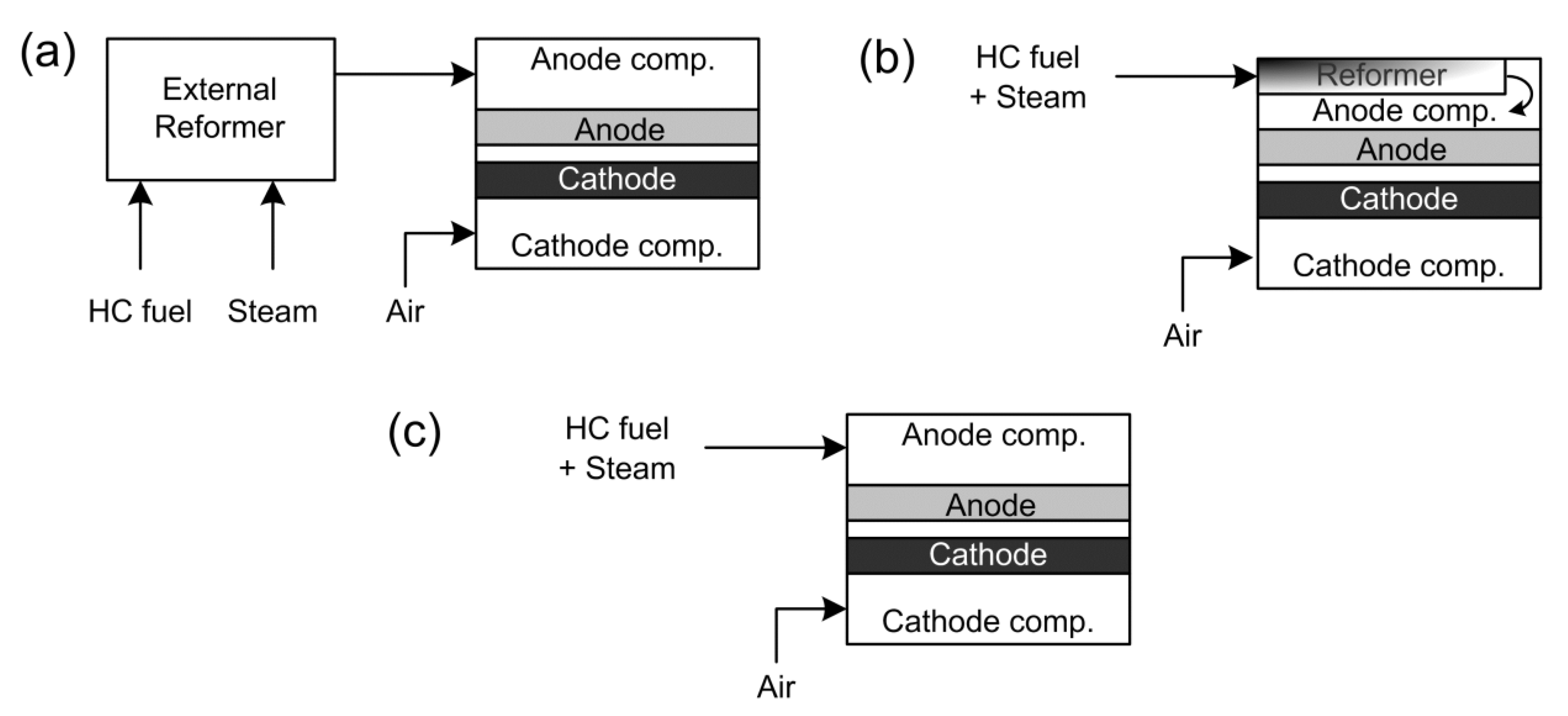
2. SOFC Operating Modes with Hydrocarbon Fuels

Four different modes are possible when a SOFC is fuelled with hydrocarbon fuels. These modes are external reforming, internal reforming, partial oxidation, and direct utilization. In the first three cases the purpose is to completely convert the fuel into synthesis gas that is afterward electrochemically oxidized. The processes of production of synthesis gas are classified into steam reforming, dry reforming, partial oxidation and auto-thermal reforming, according to the type of oxidants used.
Steam reforming of a generic alkane is represented by reaction (1). The CO produced can react further producing H2 by the water-gas shift (WGS) reaction (2).
CnH2n+2 + n·H2O → n·CO + (2n + 1)·H2
CO + H2O → CO2 + H2
The steam reforming reaction is highly endothermic (e.g. for CH4 ΔHr = 205.84 kJ/mol), while the WGS is moderately exothermic (ΔHr = −41.17 kJ/mol). Both reactions require a catalyst. On the Ni/YSZ anode, the coupling of the fast endothermic reforming reaction with the sluggish exothermic electrochemical oxidation can generate severe instabilities. An excess of steam is typically required to prevent carbon deposition by promoting the WGS reaction and reducing the partial pressure of CO.
In dry reforming, also called CO2 reforming, CO2 reacts with the hydrocarbon according to reaction (3):
CnH2n+2 + n·CO2 → 2n·CO + ½·(2n + 2)·H2
At high temperatures, dry reforming is even more endothermic than steam reforming (e.g. for CH4 ΔHr = 246.97 kJ/mol), and an excess of CO2 can promote carbon deposition but, on the other hand, CO2 is much easier to handle than steam. Both steam and dry reforming are problematic in the case of low power output, because there is not enough heat produced to sustain the reaction, and during the start-up.
Partial oxidation (POX) uses air or oxygen to reform hydrocarbons according to the following equation:
CnH2n+2 + ½·n·O2 → n·CO + (n + 1)·H2
This reaction is moderately exothermic (e.g. for POX of CH4 ΔHr = −36.01 kJ/mol compared to ΔHr = −802.62 kJ/mol for total oxidation) and couples well with the electrochemical oxidation. Part of the fuel energy is lost because the reaction is exothermic, which lowers the efficiency of the system. In addition, catalysts don’t tend to have a high selectivity for H2 and CO and high resistance to carbon deposition. Nevertheless, partial oxidation reforming is suitable for small-scale portable applications where system simplicity and rapid start-up rather than system efficiency are crucial factors.
Auto-thermal reforming integrates steam reforming with partial oxidation. In auto-thermal reforming both air and water (and partly CO2) react with the fuel according to Equations (1) to (4). Auto-thermal reforming requires a simpler design than steam reforming, has higher system efficiency than partial oxidation, and can be used to take an SOFC from zero power to operation at full load.
In typical SOFC, the reforming step is done after the desulphurization using an external unit (Figure 2a). This type of design is known as external reforming SOFC, and is convenient for large-scale stationary systems with combined heat and power generation. For small-scale applications and particularly for portable systems, however, the complexity and size of the overall system can be reduced by eliminating the external reformer and annex units [15], and reforming the fuels inside the stack. This type of design is known as internal reforming and uses the waste heat generated by electrochemical oxidation and other non-reversible processes to offset the heat requirements of the reforming reactions.
Figure 2. Schematic of (a) external reforming SOFC, (b) indirect internal reforming SOFC, and (c) direct internal reforming SOFC.
Energies 02 00377 g002
Internal reforming can be achieved either indirectly (Figure 2b), using a dedicated reforming catalyst inside the SOFC stack, or directly on the Ni/YSZ anode (Figure 2c). The indirect internal reforming (IIR-SOFC) requires ‘catalyzed hardware’ in which the surfaces of the flow channels in the anode compartment are covered by a thin layer of the reforming catalyst [16]. Indirect internal reforming is simpler and less costly than external reforming, but it can be difficult to adjust the reforming reaction to the electrochemical oxidation so that the majority of the fuel is converted into synthesis gas without residual fuel reaching the anode. The advantage in IIR-SOFC is that the reforming catalyst can be used in ultra-dispersed form, in which case noble metals can be economically competitive. The problems of IIR-SOFC are the presence of temperature gradients and carbon deposition. There is also increased sintering caused by steam contacting the Ni/YSZ anodes.
Direct internal reforming (DIR-SOFC) provides the simpler and, in principle, most efficient design. In DIR-SOFC the anode must accomplish three different roles: reform the fuel, catalyze the electrochemical oxidation of H2 and CO, and provide a path for the electrons. Part of the heat generated in the functional layer by the electrochemical reactions is used to reform the fuel in the conduction layer. The presence of temperature gradients and coking are the main limitations for DIR-SOFC. Research on direct internal reforming SOFC with Ni/YSZ anode is limited almost exclusively to methane [17,18,19,20,21,22,23], with few examples of IIR-SOFC using model fuels [24,25,26].
The application of partial oxidation and auto-thermal reforming in SOFC is conceptually analogous to indirect internal reforming. Also in this case a dedicated catalyst must be used for the partial oxidation of the fuel. Only a few studies on this operating mode have been published [27,28,29].
Direct utilization of hydrocarbons in SOFC implies that the fuel is added directly to the anode without any preliminary treatment and/or the addition of an oxidant [1]. The anodic reaction can be either the electrochemical oxidation of the products formed by decomposition of the fuel or the partial electrochemical oxidation of the fuel molecules themselves. Rigorously, direct electrochemical oxidation of a hydrocarbon occurs only when all the reaction steps are electrochemical in nature (i.e. involving charge transfer). The overall electrochemical oxidation of a generic hydrocarbon can be represented by the following overall reaction:
CnH2n+2 + (3n + 1)·O2- → n·CO2 + (n + 1)·H2O + (6n + 2)·e-
Equation (5) describes only the anodic half-cell reaction (reactants and products) and not the actual electrochemical mechanism that is likely to proceed through multiple one-electron exchange steps [30]. Recently, the direct oxidation of hydrocarbons in SOFC has been the object of controversy [31,32]. While Gorte and Vohs [31,33,34,35] argued that hydrocarbons can be directly oxidized using ceria-based electrodes, according to Mogensen et al. [32], only H2 is oxidized on Ni-YSZ anodes fed with dry hydrocarbons because the oxidation of methane and other hydrocarbons is significantly slower than that of H2. Consequently, hydrocarbon cracking, reforming and WGS reactions are likely to happen at a much faster rate, producing H2 that is the actual electrochemical fuel of the SOFC. The carbon deposited by cracking will react with the water produced from the oxidation of hydrogen to give carbon monoxide and more hydrogen, which in turn can be oxidized. According to this line of reasoning [32], the terminology ‘direct oxidation’ is inappropriate, while ‘direct utilization’ that denotes only a mode of operation rather than the actual chemistry is preferred.
The reactions of steam and dry reforming on the SOFC anode remain important for the direct utilization of hydrocarbons, since the partial pressures of H2O and CO2 increase with increasing fuel consumption. Accordingly, it is likely at high current loads that the fuel molecules are reformed on the anode rather than oxidized electrochemically.
The primary problem in the direct utilization of hydrocarbons is the rapid and irreversible deactivation of the anode caused by carbon deposition. Theoretically, it is possible to remove the carbon by reaction with the oxygen ions according to reaction (6).
C(s) + 2·O2- → CO2 + 4·e-
In fact, carbon deposited near the triple-phase boundary (TPB) is removed at a certain current load when operating outside the carbon deposition boundaries, indicating that the electrochemical oxidation of solid carbon deposits could be possible [36,37,38]. Horita et al. [36] demonstrated this process of carbon removal by reaction with O2- using Secondary Ion Mass Spectrometry (SIMS) and isotopic labeling studies. However, the reversibility to poisoning from carbon deposition depends strongly on the anode materials.
The final application for the SOFC dictates the system design, the fuel, and consequently the mode of operation. External reforming of natural gas is the most convenient option for stationary applications where the volume of the system, the start-up time, and the power fluctuation are not crucial. Partial oxidation and direct utilization of a liquid fuel are suitable operating modes for those applications that require maximum power density, which is typical of military portable power generation (e.g. for radio communication, weaponry and navigation) and civil applications (e.g. generators for leisure ships and in remote campgrounds). If achievable, the direct utilization of a liquid fuel with satisfactory durability is the most efficient way of converting the chemical energy of that fuel. Maximum efficiency means minimum CO2 emissions per unit power produced.

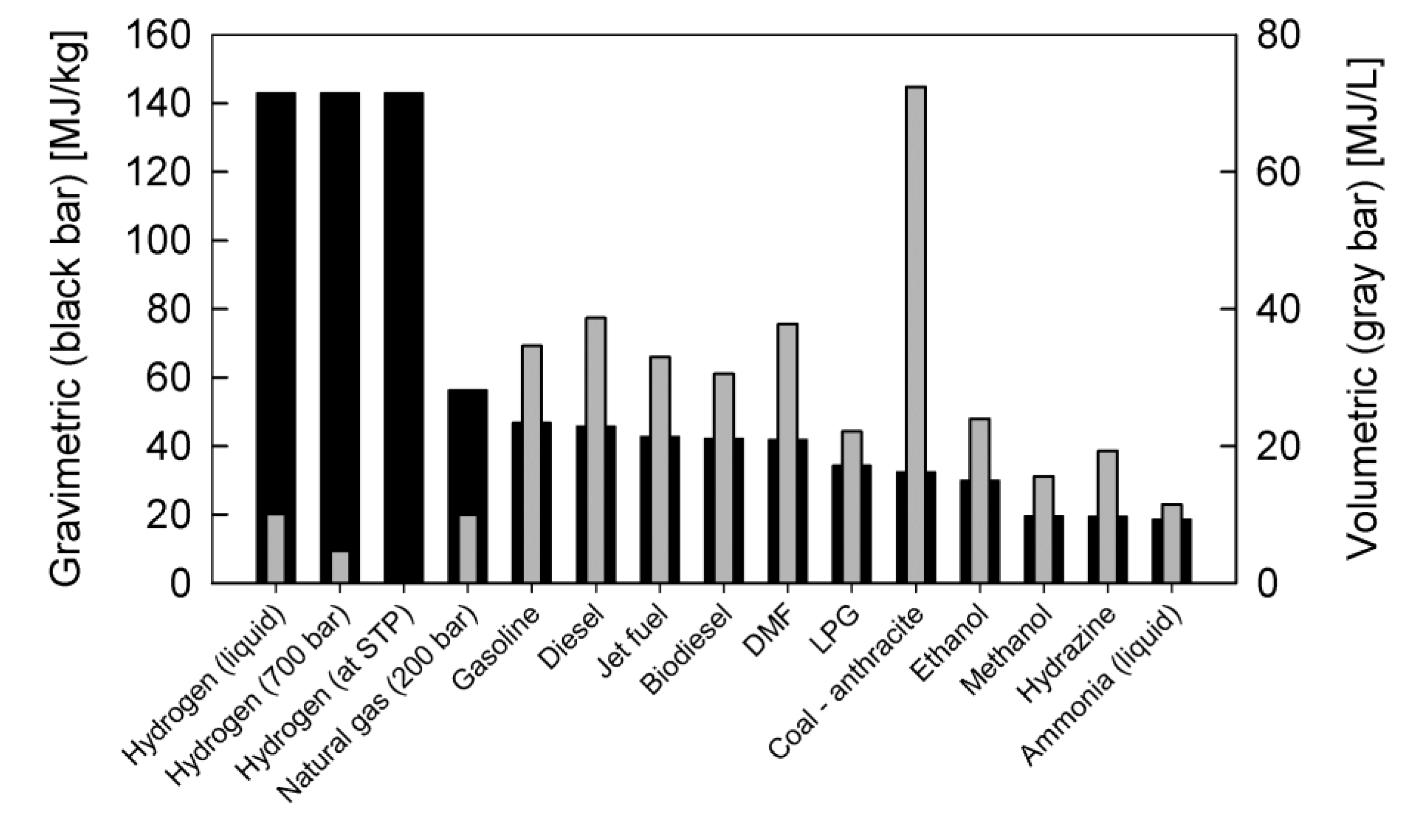
3. Liquid Fuels for SOFC

Several factors determine the suitability of a liquid fuel for direct utilization in SOFC. The main factor is the propensity of the fuel to form coke at the high temperatures (> 600 °C) and reducing conditions found in the anode compartment. Other important factors are the energy density and the physical state of the fuel at standard conditions, which determine how easily the fuel can be stored and fed to the SOFC, as well as the availability and cost of the fuel, which are related to the abundance of the feedstock from which the fuel is produced and to the costs and capacity of production. Toxicity and environmental impact are also factors to consider.
Several alternative and traditional liquid fuels have been considered for internal reforming, partial oxidation, and direct utilization. In the following sections, the advantages and disadvantages of methanol, ethanol, dimethyl ether, liquefied petroleum gas, and carbon-free liquid fuels are examined.

3.1. Methanol

Methanol (CH3OH, MeOH) is a light, volatile, colorless, flammable, poisonous liquid. MeOH is used mainly as an antifreeze additive, solvent, and denaturant for ethanol. MeOH is completely miscible in water and in most organic solvents, and it is capable of dissolving many inorganic salts. Typical commercial grade MeOH contains 99.85% methanol with water (MeOH is hygroscopic), acetone, formaldehyde, ethanol, and methyl formate being common impurities.
MeOH is toxic and rated as a severe poison, but is not carcinogenic and is not considered particularly harmful to the environment [39]. The environmental hazard arises primarily in relation to the use of MeOH as a fuel, particularly for air pollution by combustion and groundwater contamination in case of spills. Because MeOH is readily biodegradable, the environmental risk posed by MeOH as a fuel is small compared to gasoline.
MeOH was traditionally obtained by destructive distillation of wood. In 1923, BASF introduced a process based on the conversion of synthesis gas, derived from coal gasification. In 1966, ICI developed a low-pressure process (catalytic hydrogenation of CO) that to this day is the dominant technology [39]. Recently, the production of MeOH from synthesis gas obtained from thermal decomposition of organic materials, such as wood (Biomass-to-Liquid), has been reconsidered as an alternative to produce renewable MeOH fuel. Although the use of MeOH as fuel has a long history [40], its use in internal combustion engines (ICE) is limited to few applications, mainly because of the lower energy density (19.7 MJ·kg-1) relative to gasoline (Figure 3) and the corrosive properties of MeOH for some metals and for rubber (e.g. in the fuel-delivery system) when compared to other hydrocarbons.
Recently, a hypothetical ‘Methanol Economy’ was proposed that envisions MeOH as the foremost energy vector [41,42,43]. Several motivations are used to support this idea. Namely, the production technology is mature and the existing infrastructure for distribution of traditional fuels can be used for MeOH; MeOH can be produced from natural gas and biomass, and can also be obtained using the CO2 captured from thermoelectric power plants and converted by catalytic hydrogenation of CO2 [44]. The adoption of MeOH as an energy vector may allow a faster transition from a fossil fuel to a renewable energy system, as the production of MeOH should initially rely on natural gas, and later switch to renewable sources via atmospheric-CO2 capture and electrochemical CO2 reduction. The main drawback of the Methanol Economy, however, is that it is ultimately based on energy sources, such as solar, that cannot meet the current demand until there is a technological breakthrough. Moreover, while relying on fossil fuels as a main energy source there would be no net reduction of the CO2 produced.
Since the first developments of low temperature fuel cells, MeOH has been considered both as a hydrogen-source and as direct fuel [45]. The utilization of MeOH in SOFC has not been fully explored, mostly because SOFC are traditionally intended for stationary applications. However, it would be meaningful to directly use MeOH in SOFC for small-scale portable applications for the following reasons: MeOH is a liquid with high volumetric energy density that can be easily stored and transported; the content of impurities that can poison the anode is low; the amount of carbon predicted at equilibrium is significantly lower if compared to ethanol, LPG, gasoline or diesel; pyrolysis and catalytic decomposition of MeOH can be readily achieved at the typical SOFC anodic conditions favoring subsequent electrochemical oxidation of the products of these reactions.
Figure 3. Energy densities of different fuels.
Energies 02 00377 g003

3.2. Ethanol

Ethanol (CH3CH2OH, EtOH) is a liquid, flammable, colorless, and mildly toxic compound. EtOH is a versatile solvent, completely miscible with water and many organics, and partially miscible in light aliphatic hydrocarbons. The presence of a hydroxyl group (OH) is the origin of most chemical properties of EtOH, such as polarity, viscosity and volatility, and hygroscopicity. Mixtures of EtOH with water behave in unusual ways, including having a negative volume of mixing, reduced surface tension at very low concentrations of EtOH, and an azeotrope at 95.6 wt% EtOH with a boiling point of 78.1 °C [46]. EtOH is typically commercialized in two different grades: absolute, and denatured. Absolute or anhydrous alcohol is purified EtOH that contains < 1% water. Denatured alcohol is an EtOH/H2O mixture below the azeotropic point (H2O > 5%) that contains methanol, benzene and acetaldehyde to provide toxicity, and denatonium benzoate to adulterate the taste.
EtOH is not harmful to the environment and pure EtOH is not classified as carcinogenic (although beverages containing EtOH are). Spills of EtOH do not pose a threat for surface water or groundwater because of the high solubility and biodegradability of EtOH. EtOH can be produced both from conventional petrochemical process (catalytic hydrogenation of ethylene), and biologically by the fermentation of sugars. The selection of the production process depends on the final use. The majority of the EtOH used as fuel and all the EtOH used in beverages are obtained by fermentation. The typical product of fermentation contains less than 10–15 vol% of EtOH.
In order to produce ethanol from starchy materials, such as corn, first starch must be converted into sucrose by hydrolysis with diluted sulfuric acid or by addition of industrially produced amylase. In North America all EtOH fuel is obtained from corn, while in other countries such as Brazil, EtOH is obtained from sugarcane. An emerging technology to produce EtOH is through the use of cellulose. The traditional process (chemical hydrolysis) is not economically convenient for large-scale fuel production. To enhance the energy balance for the production of cellulosic EtOH which is currently lower than 45%, biotechnologists are trying to replicate the bacteria contained in the guts of termites [47], with the objective of obtaining enzymes that can attack the cellulose. The success of this technology could turn biomasses containing cellulose into cheap and renewable energy sources. Algae could also be source of cheap EtOH fuel and biodiesel using an engineered photosynthesis process that captures the CO2 from industrial stacks. For most industrial uses and particularly for fuel applications , fermented EtOH solutions require distillation and purification that are energy intensive and costly [48].
EtOH has been used as a fuel for internal combustion engines since the start of the car industry —the first car produced on an industrial-scale (Ford Model T in 1910) was fuelled with ethanol. Nowadays, certain types of ICE are designed to obtain the maximum power using pure EtOH or gasoline blends (flex-fuel) [49,50]. According to the Canadian Renewable Fuel Association, over 1 billion liters of EtOH fuel were produced in Canada in 2007 [51]. In the last five years, the prospect of using EtOH and other biofuels as the main source of energy (EtOH Economy) has found strong support and created equally strong controversy, particularly in the U.S.A. [52]. The advantages of using EtOH are the reduction of CO2 emissions, the reduction of other pollutants (i.e. ozone), and the revitalization of rural areas (i.e. American Midwest and Canadian Prairies). EtOH can be considered as a completely renewable source of energy since the CO2 produced by combustion of EtOH is reconverted into sugar by plants with zero net emissions. On the other hand, the ‘Ethanol Economy’ has also strong opponents, with equally valid motivations. The main critique concerns the production of EtOH fuel from corn or other grain crops that should be used mainly as a food source [53]. Furthermore, recent studies [54] have demonstrated that the production of Corn EtOH gives an energy gain of only 35%. A large increase in demand of EtOH fuel would imply that new farmland is obtained from the wilderness or from conservation areas. The energy gain in the case of EtOH from sugar cane is almost 700%. However, sugarcane cultivations require a humid and temperate climate, making the ‘EtOH Economy’ possible only in countries like Brazil [52] or Cuba. A possible solution could come from a biotechnological breakthrough in the production of EtOH from cellulose [52].
The utilization of EtOH in fuel cells has been considered only recently. Similar to MeOH, EtOH should be seen mainly as a fuel for small portable applications, particularly for remote rural locations. The advantages are that EtOH is an ultra-clean liquid fuel with reasonable energy density (Figure 3). However, EtOH is harder to oxidize than H2 and MeOH. The direct utilization of EtOH has been tested in PEM fuel cells using Pt-Ru anodes similar to direct methanol fuel cells (DMFC), and only partial oxidation of the fuel can be obtained [55]. The utilization of EtOH as a source of hydrogen is also under investigation [56]. In general the reforming of EtOH is more problematic than natural gas and MeOH, particularly because of coking. The internal reforming and the direct utilization of EtOH in high temperature fuel cells are virtually unexplored.

3.3. Dimethyl Ether, Liquefied Petroleum Gas, and Other Conventional Liquid Fuels

Dimethyl-ether (CH3OCH3, DME) is the simplest ether. At standard conditions DME is a gas but it is typically stored and shipped as a liquefied gas under its own vapor pressure of 430 kPa (4.24 atm) at 20 °C. DME is typically prepared by dehydration of MeOH and can be obtained from natural gas and biomass. DME is not classified as toxic, although direct contact with the liquefied gas may cause chilling of the skin or frostbite. DME does not pose significant environmental concerns and is mainly used as a low-temperature solvent in laboratory synthesis, as an aerosol propellant in canisters, and recently as a possible clean-fuel [57,58]. DME has been considered as a convenient source of H2 [59,60,61] and also a potential fuel for SOFC [62,63].
Liquefied petroleum gas (LPG), a mixture of propane (> 90%) with butane (ca. 5%), propylene and odorants is a conventional fuel and is perceived as the ideal SOFC fuel for small-scale (1–10 kW) stand-alone applications in remote areas [15]. LPG has been considered both as a source of H2 for internal reforming SOFC [64] and also for partial oxidation [65,66,67] using traditional Ni/YSZ anodes. The problem of carbon formation on Ni anodes is more severe with LPG than with natural gas, and consequently, coke resistant anodes [68,69] must be developed for the direct utilization.
Gasoline, diesel, biodiesel and jet fuels pose severe coking problems for reforming processes. These fuels have a low H to C ratio and a high content of aromatic hydrocarbons that makes the decomposition to carbon always thermodynamically favorable. Nevertheless, the direct utilization of these fuels has been pioneered in SOFC using carbon tolerant anodes [35], as discussed in more detail later.

3.4. Carbon-free Liquid Fuels

Among the alternative fuels, ammonia and hydrazine do not contain carbon and could be used on traditional Ni/YSZ anodes without risks of coking. Ammonia (NH3) is one of the most important chemical compounds in industry and is used in the synthesis of fertilizers and explosives. At standard conditions, NH3 is gaseous, but typically stored as an anhydrous liquid under pressure. Currently, ammonia has been proposed as a practical alternative to fossil fuel [70]. The main advantages of ammonia-fuel are the low cost, simple storability as a liquid with high energy density, and the fact that ammonia oxidation does not produce carbon dioxide. Concentrated ammonia, however, is strongly corrosive and can be deadly at exposure levels above 5,000 ppm, which poses serious risks for practical applications. Recently NH3 has been considered as a possible fuel for SOFC. Experimentation on Ni/YSZ anodes showed comparable performances in NH3 and H2; the analysis of gaseous species at the cell outlet revealed that ammonia was completely decomposed to H2 and N2 [71].
Hydrazine (N2H4) is a colorless liquid compound obtained during the process of production of NH3. Its physical properties are similar to those of water but N2H4 is highly toxic and chemically unstable; for this reason it is stabilized in water. The main use of N2H4 is in the production of polymers and fine chemicals, and as a rocket fuel. Previously, N2H4 was considered as a 'compromise fuel' for low temperature fuel cells [45,72] but is now being reconsidered both as a source of H2 and directly as a fuel for low temperature fuel cells [73]. As an alternative to H2, N2H4 has some advantages: it can produce more power than a similar H2 cell without the need to use Pt catalysts; it can be handled and stored more easily than H2; and it has a higher electromotive force (see Figure 4) than H2. Although N2H4 could be potentially used also for SOFC, there is no record of its use. Hydrazine is the most expensive of all alternative fuels.

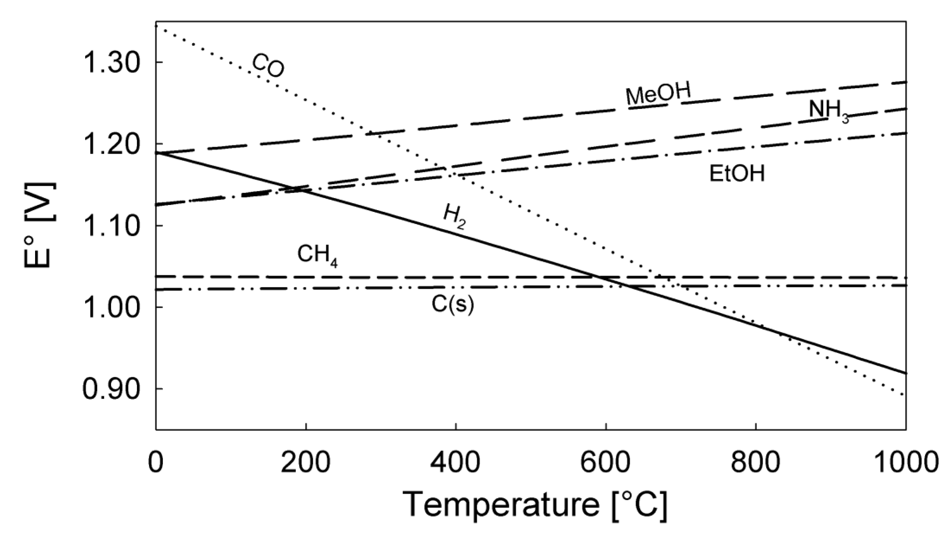
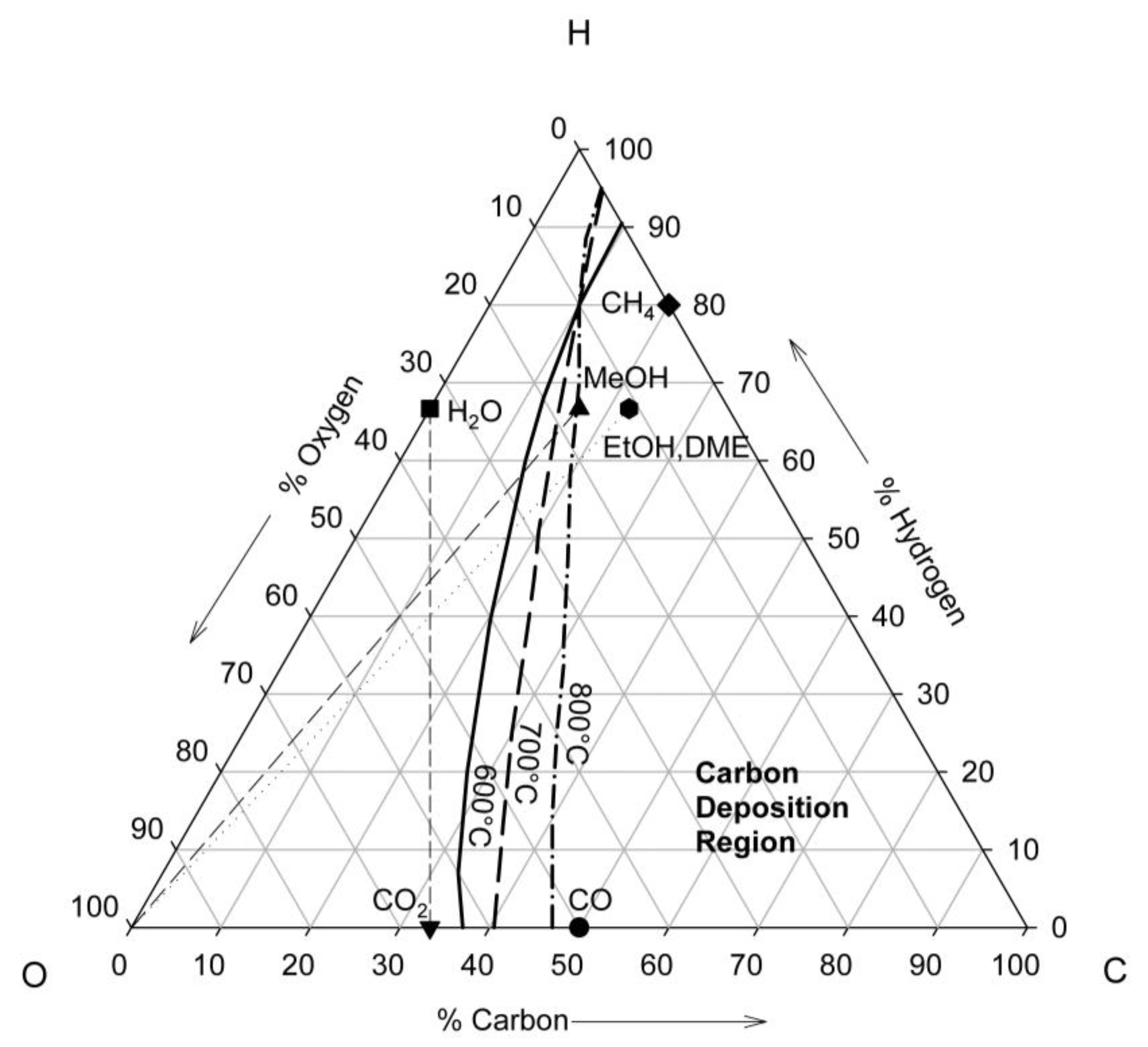
4. Thermodynamics of Direct Utilization SOFC

The maximum electrical work (Welect) obtainable in a fuel cell operating at constant temperature and pressure is equivalent to the change in Gibbs free energy (ΔG) of the electrochemical reaction:
W e l e c t = Δ G = z F E
where z is the number of electrons involved in the reaction, F is Faraday's constant and E is the equilibrium potential of the cell. The Gibbs free energy change of a reaction at temperature T is generally expressed as a function of the activities (or fugacities) of the species involved, which at high temperatures (> 500 °C) and low pressures (1–2 atm) can be assumed equivalent to the partial pressures, Pi, (Pi = yi∙P, where yi is the mol fraction of species i and P is the total pressure). The Nernst equation, equation (7), is derived from equation (6) and gives the ideal potential of the cell (see [1] for a complete derivation):
E = E o R T z F ln ( i P i ν i )
where Eo is the ideal standard potential of the fuel cell at temperature T assuming that all fugacities are equal to one. The ideal standard potential for several fuels as a function of the temperature is shown in Figure 4. The Nernst equation provides a relationship between the ideal standard potential () and the equilibrium potential (E) at the actual partial pressures of reactants and products for a given fuel cell reaction. This potential identifies the electromotive force (EMF) of the fuel cell.
The equilibrium potential calculated using equation (7) is typically close to the measured open circuit potential (OCP) for SOFC with H2, but for hydrocarbons and alcohols, this value is always overestimated, and the measured OCP may vary with time [74], possibly in response to changes in the local anodic composition generated by the catalytic decomposition of the fuel. When the fuel can decompose within the anodic compartment, it is more relevant to calculate the equilibrium potential together with the equilibrium composition in the anodic compartment.
Figure 4. Ideal standard potential as a function of temperature for selected fuels.
Energies 02 00377 g004
Carbon formation is one of the causes of instability in SOFC operating with hydrocarbon fuels. Hydrocarbons can react on the metal surface of the anode and also in the gas phase via free-radical cracking and polymerization, forming tars that will eventually precipitate and foul the anode surface. Carbon deposition is thermodynamically favorable at the conditions of the anode compartment (i.e. pO2 < 10-20 atm and T > 700 °C). Regions of stable operation, in terms of carbon deposition, can be identified by thermodynamic calculations, as shown in [75]. Triangular diagrams such as Figure 5, are the most compact way of representing biphasic (gas and solid) C-H-O systems in equilibrium [76,77].
For each temperature, a line indicates the carbon deposition boundary and defines two regions: on one side of the boundary (to the right of the line in Figure 5), the gas phase and solid carbon coexist; on the other side (to the left of the line in Figure 5), solid carbon is unstable and only gas phase species are present at equilibrium. Figure 5 indicates that fuels such as CH4, MeOH and EtOH fall inside the region of carbon deposition for temperatures lower than 800 °C. As is typically done for stable SOFC operation, steam is added to the fuel such that the gas phase mixture lies outside the carbon deposition region. The minimum amounts of H2O and/or CO2 that are required to avoid carbon formation can be calculated using the lever rule. In practice, kinetics as well as thermodynamics plays a role in determining how much carbon will be deposited.
Another way to express the equilibrium conditions for a given fuel is to plot the equilibrium compositions and potential profiles versus temperature such as in Figure 6. Note that as the temperature increases, carbon (as graphite, which is the lowest energy form of carbon) is less thermodynamically favored, while carbon monoxide and hydrogen are more thermodynamically favored. The increase in the fraction of hydrogen in the gas phase results in an increase in the equilibrium potential with temperature.
Figure 5. Equilibrium carbon deposition boundaries for the C-H-O system at 1 atm. Lines represent the carbon deposition boundary for the temperature indicated. Calculated according to ref. [75].
Energies 02 00377 g005
The equilibrium composition and electromotive force of a fuel cell at a given temperature can also be represented as a function of the fuel utilization, which is related to the current produced and the flow rate of oxygen through the electrolyte. When the cell is operating, H2O and/or CO2 will be produced and these products will influence the thermodynamic stability of carbon (Figure 5). Figure 7 shows the equilibrium conditions for a SOFC operating directly with MeOH and EtOH at 800 °C. The shaded areas in the figure indicate the regions in which carbon formation is predicted. At this temperature, MeOH decomposes to H2 and CO, through the decomposition reaction of CH3OH = 2 H2 + CO [78]. Although some carbon (< 2 mol%) is thermodynamically predicted at low fuel utilizations, in practice the presence of small quantities of H2O in the MeOH fuel should be sufficient to suppress the formation (e.g. ~2.6 vol% H2O is required for a SOFC operating at 800 °C). Additionally, once the fuel utilization exceeds 2.1% the SOFC will operate in a carbon free region.
The predictions are similar for EtOH (Figure 7b) but a fuel utilization of 19.5% is required at 800 °C to be in a carbon-free region [78]. Ethanol decomposes according to the reaction: C2H5OH = 3 H2 + CO + C. This reaction dictates the equilibrium products above 850 °C; below this temperature, other reactions cannot be neglected. The equilibrium results for EtOH steam-reforming indicate that relatively large amounts of H2O must be added to pure EtOH in order to prevent coking. For example, at least 1.125 moles of H2O should be added per mole of EtOH to prevent coking at 800 °C in the case of internal reforming operations.
Figure 6. Equilibrium compositions (symbols) and potentials (solid lines) as a function of temperature for (a) MeOH and (b) EtOH pyrolysis. The species are (●) CH4, (○) CO, (▼) CO2, (△) H2, (■) H2O, and (□) C (graphite). Adapted from [78].
Energies 02 00377 g006
Figure 7. Calculated equilibrium compositions (symbols) and electromotive forces (EMF, solid lines) for a SOFC operated at 800°C with dry MeOH (a) and EtOH (b). The species are (●) CH4, (○) CO, (▼) CO2, (△) H2, (■) H2O, and (□) C (graphite). The carbon deposition boundary (CDB) identifies the minimum fuel utilization to avoid coking at equilibrium. Adapted from [78].
Energies 02 00377 g007
Stability maps and concentration profiles are extremely useful to define the equilibrium state of a system, but there is no guarantee that any mixture of components will actually attain equilibrium and reach the composition identified in the diagram. At high temperatures (> 1,000 °C) equilibrium is typically reached within a tangible timeframe, but the complexities associated with the actual processes carried out in the anode compartment of SOFC still bring uncertainties that equilibrium calculations cannot solve. In fact, the anode compartment of an SOFC fuelled with hydrocarbons or alcohols is never at equilibrium. The coupling of gas-phase and heterogeneous catalytic conversion of the fuel with the electrochemical oxidation and transport processes can generate local conditions where carbon formation is strongly favorable even when it is not predicted from equilibrium calculations. In addition, once carbon is deposited it can be very difficult to remove even when it becomes thermodynamically unstable. Nevertheless, the equilibrium conditions described in this section are indicative of the final state towards which the system is evolving.

5. Kinetics in the Anode Compartment

Some of the possible reaction pathways for a generic hydrocarbon or alcohol molecule in the anode compartment are illustrated in Figure 8. The fuel can react in the gas-phase (pyrolysis in the flow channels and anode pores) forming fragments. Next, the pyrolysis fragments and unreacted fuel molecules can decompose on the anode surface (catalytic decomposition on the conductive layer of the anode) producing more fragments, including adsorbed intermediates. After that, the fragments of thermal and catalytic decomposition — and possibly also undecomposed fuel molecules — can undergo partial or full oxidation reacting with the oxygen ions transported through the electrolyte (electrochemical oxidation). The products of the complete electrochemical oxidation are H2O and CO2. The presence of H2O and CO2 in the anode compartment allows new reaction pathways in which the fuel molecules are reformed to H2 and CO (steam and dry reforming). Simultaneously, H2O reacts with the CO produced by decomposition and reforming to give H2 and more CO2 (water-gas shift). Besides these processes, carbon formation and removal reactions (coking) may also be occurring.
Figure 8. Schematic of a planar SOFC (a) and cross-section (b) including the processes involved in the direct utilization of hydrocarbons in SOFC. WGS is the water-gas shift reaction.
Energies 02 00377 g008
The processes illustrated in Figure 8 are coupled and depend on the cell temperature, pressure, and flow conditions, as well as the catalytic properties of the anode. The rate of the electrochemical oxidation is also a function of the current density at which the cell is operated. Fuel flow-rate and overall current determine the fuel utilization that is proportional to the amount of H2O and CO2 produced in the anode compartment. Consequently, the relative importance of the reforming and water-gas shift reactions depends directly on the fuel utilization. This dependence means that varying the current produced modulates the processes shown in Figure 8. At OCP, reforming and shift reactions are negligible, but as the fuel utilization increases, the amounts of H2O and CO2 produced increases, thus providing reactants for the reforming reactions. When the fuel utilization is greater than a critical value there is enough H2O and CO2 that the reforming reactions become predominant and no coke is formed.
The following sections provide an overview of the work done on pyrolysis reactions, carbon formation, and electrochemical reactions with liquid fuels. Pyrolytic processes in the anode compartment are relevant because they influence what gas composition reaches the anode surface. The rate of the pyrolysis reactions depends mainly on the temperature, space velocity and flow conditions in the anodic compartment. Only a few studies have been published on the gas-phase kinetics within the anode channels of SOFC [79,80,81,82,83,84]. Walters et al. [79] predicted the propensity of coke formation in the anode channels of SOFC fuelled with dry natural gas by applying a simple gas-phase kinetics model of CH4 pyrolysis and oxidation, and relating the rate of formation of cyclic hydrocarbon species to the propensity of carbon deposition. Sheng et al. [80] demonstrated that substantial gas-phase chemistry occurs in SOFC fuelled directly with n-butane by using a complex kinetics model to predict the conversion of butane pyrolysis. Hecht et al. [81] studied reforming of CH4 on Ni/YSZ anodes and added the non-electrochemical heterogeneous reforming chemistry to a kinetics model including the pyrolysis of the fuel. Gupta et al. [82] applied a model including the gas-phase chemistry to predict the performance of a tubular SOFC fuelled with partially reformed JP-8 (Jet) fuel. Randolph et al. [83] presented a study on the pyrolysis of n-hexane in SOFC. Gupta et al. [84] focused on the propensity for molecular-weight growth and deposit formation in the non-catalytic regions of SOFC fuelled with butane and EtOH; they concluded that EtOH decomposes mostly to CO, H2 and CH4, with substantial quantities of H2O and C2H4, which was related to the increased propensity for soot deposition.
Catalytic decomposition and reforming of the fuel within the pores of the anode are the second most important process (after electrochemical oxidation) in the direct utilization of liquid fuels in SOFC. The catalytic properties of the anode material towards the decomposition of the fuel determine the composition of the gas-phase. Higher conversion to H2 and CO will result in faster electrochemical oxidation (i.e. lower activation overpotential). Catalytic decomposition and reforming can generate concentration gradients through the anode thickness. These gradients depend on the intrinsic activity of the catalyst, on the pore structure, and on the mass transfer and reaction rates in the porous layer. Reforming reactions have been extensively studied [57,85,86,87], while catalytic decomposition reactions have been less well studied in relation to the reforming reaction for MeOH [88,89,90] and are essentially unexplored for other alternative fuels. A recent study [91] on the catalytic decomposition of MeOH on metal/ceria has shown that initially the conversion of MeOH is essentially complete and the composition is equal to that predicted from thermodynamic equilibrium calculations. Over time, the composition departs from equilibrium and approaches the values obtained by pyrolysis only. The change in activity of the catalyst is related to the parallel reaction of carbon formation that causes the fouling of the active surface.
The mechanism of carbon formation is complex. A general distinction is made between the carbon originating in the gas-phase (pyrolitic carbon) and that deposited with the intervention of a catalytic surface (catalytic carbon). Pyrolytic carbon, known also as soot, is usually composed by amorphous carbon that can be partially hydrogenated. The formation of soot is believed to involve the formation of precursor species, including ethylene (C2H4), acetylene (C2H2), radicals (such as ∙CH3), as well as monoatomic and diatomic hydrogen. The precursors recombine to form polycyclic aromatic hydrocarbons (PAHs) [80,92] that grow and agglomerate, then condense and precipitate on the surface of the anode. Once soot has been deposited in the anode compartment, the soot can rearrange and change in phase, depending on the local conditions. This aging process typically gives more stable graphitic carbon. As in flames, pyrolytic carbon formation in SOFC is not significant for methane, but is relevant for all other hydrocarbons and alcohols.
Catalytic carbon is typically formed on metals (e.g. Ni, Fe, and Co). This problem has been extensively studied for hydrocarbon-reforming processes [93,94,95,96,97]. The morphology of the carbon deposit depends on many factors including temperature, feed [98,99], anodic polarization [100], and type of catalyst used. In particular, different types of carbon may form in the functional and conduction layers of the anode. The reactions in the conduction layer include the reforming and decomposition reactions as described above. The extent of these reactions depends on the operating conditions, anode material [74,91], and the initial gas phase composition [91,99], and determines which species reach the functional layer that contains the TPB. On Ni/YSZ exposed to methane [98], carbon fibers form at temperatures up to ~700 °C. Above this temperature, the majority of the carbon dissolves into the Ni particles, causing an increase in volume which can lead to stress and eventually cracks and/or delamination within the cell. At the TPB, at which the electrochemical reactions occur, the amount of carbon formed is significantly reduced due to the presence of produced water and/or oxygen ions [100]. Examples of the carbon formed ex-situ and in-situ on Ni/YSZ anodes exposed to methane can be found in references [98,99]. Examples of the different carbon morphologies on various SOFC anodes tested for the direct utilization of EtOH are shown in Figure 9. The image in Figure 9a is typical of the prepared anodes before testing. Numerous carbon fibers were formed on the Ni/YSZ anode after exposure to EtOH (in Figure 9b), while several types of carbon (fibers and amorphous) were formed on Ni/CeO2 (in Figure 9c). Figure 9d is an extreme example of carbon formation on Cu/CeO2 exposed to EtOH, on which micron-sized carbon fibers were formed.
Once the species get to the active region of the anode (the TPB), electrochemical oxidation occurs in an operating SOFC. In principle, the electrochemical oxidation of simple hydrocarbons or alcohols, as well as of the products of thermal and catalytic decomposition of these fuels, is feasible in SOFC. It has been argued [32] that in reality only H2 is oxidized electrochemically in direct utilization operations, while the other molecules, included CO, are catalytically converted by reforming and water gas-shift reactions providing more H2 for oxidation. Other studies have shown that the electrochemical oxidation of CO and also C might be possible [101,102], but these studies also confirmed that the overpotentials of these reactions on Ni/YSZ are orders of magnitude higher than for H2. However, the situation could be different with other anode materials. Thus, it would be desirable to determine the inherent electrochemical oxidation rates for all the species reaching the anode for the assessment of alternative anode materials. However, it is only possible to measure the electrochemical oxidation independently from the decomposition and reforming processes for H2 and CO [103]. The value of the relative rates of electrochemical oxidation for H2 and CO provides an indirect indication of the propensity to form coke on the anode. The ratio of rates indicates if there is propensity for the accumulation of CO and for the corresponding increase in the driving force for the formation of carbon [78]. For direct utilization SOFC, it would also be interesting to determine whether carbon deposits can be oxidized electrochemically.
Figure 9. Scanning electron microscopy micrographs of a Cu/ZDC (a) as prepared, and Ni/YSZ (b), Ni/CeO2 (c), and Cu/CeO2 (d) exposed for 20 to 100 h to EtOH at 800 °C. Adapted from [104].
Energies 02 00377 g009

6. Survey of Anode Materials for the Direct Utilization of Hydrocarbons and Liquid Fuels

While the oxidation of H2 and syngas in SOFC has been extensively studied, research on direct utilization of hydrocarbons gained momentum only in the last decade. Several review papers [104,105,106,107,108,109,110,111] and books [112] have appeared in the last few years on alternative anode materials for SOFC. The review published by Sun and Stimming [113] gives an exhaustive overview of all the anodic compositions considered so far. In the present review, we provide only a survey of those materials that have potential as anodes for the direct utilization of liquid fuels, such as MeOH and EtOH, and focus on performance and stability to coking.
Ni/YSZ anodes were the first anodes to be tested directly with hydrocarbons, but stable performance was achieved only for CH4. Weber et al. [101] tested a single cell (Ni/YSZ|YSZ|LSM) in H2, CO, and dry CH4 (at 800 °C), and found that stable operation was possible for up to 1,000 h. Similarly, Liu et al. [19] found that Ni/YSZ anodes were stable in humidified methane for more than 90 h at 700 °C, producing a power density of 0.35 W/cm2. Later, Lin et al. [114] tested similar cells in dry methane and found that the direct utilization of CH4 was not affected by carbon formation if the cell was operated below 700 °C; at higher temperatures increasingly higher current densities were required to avoid coking. At 750 °C and current densities lower than 0.4 A/cm2, the Ni/YSZ anode was poisoned in less than one hour. In addition, Kim et al. [35] performed several tests in which Ni/YSZ cermets were exposed ex-situ to various hydrocarbons (e.g. ethane, n-decane and toluene) and found that the microstructure of the anode was severely and irreversibly damaged in less than 90 min for all fuels. Thus, only the direct utilization of methane is possible on Ni/YSZ anodes, provided that the operating temperature is low (< 700 °C), and that the cell is operated at high current densities.
Various dopants have been added to Ni/YSZ anodes to reduce coking for internal reforming operations. These dopants include gold [115,116], tin [117], molybdenum [118], CaO and MgO [119]. There is no record, however, of these compositions being used for the direct utilization of liquid fuels. Recently, it has been found that the substitution of YSZ with scandia-stabilized zirconia (ScSZ) improves the stability under coking conditions [120,121], but any attempt to directly utilize higher hydrocarbons resulted in rapid deactivation [122].

6.1. Early Studies on Alternative Anodes

One of the earlier studies on alternative Ni-free anodes for the direct oxidation of hydrocarbons was reported by Pudna et al. in 1995 [123]. In that work, a samaria-doped ceria (SDC) anode impregnated with rhodium was used to oxidize dry methane. Both SDC and rhodium were found to have an important role, producing a power density in methane that, although modest (ca. 0.010 W/cm2 at 750 °C), was equivalent to that obtained in H2.
The use of a Ni/YSZ anode with a yttria-doped ceria ((Y2O3)0.15(CeO2)0.85, YDC) interlayer fuelled directly with methane was another way to reduce coking [124]; the power densities obtained in methane (0.370 W/cm2 at 650 °C) were comparable to those typically obtained with H2, and also the stability of the anode was good with no carbon deposition after 100 h. According to the current understanding of the mechanism of electrochemical-oxidation, ceria serves as an oxidation catalyst for CO and adsorbed carbon, simultaneously favoring the transport of oxygen ions, while Ni serves as a cracking catalyst and the main electron conductor phase [32]. Other experiments using ethane revealed that coking still constitutes a problem with Ni/ceria anodes [125]; therefore, this anode composition was not considered suitable for higher hydrocarbons.
Subsequently, researchers perceived that catalytic carbon formation on Ni was the limiting factor for the direct utilization of hydrocarbons in SOFC, and substitutes for Ni were sought. The ideal metal to replace Ni must be easy to maintain in the metallic state (i.e. similar redox properties), easy to process and catalytically inert towards carbon formation. Cobalt and iron have been tested as a replacement for Ni, but exhibit similar properties towards carbon formation [126]. Copper-based anodes have been tested [127] and it was demonstrated that copper is highly resistant to carbon formation. The performance of the Cu/YSZ anodes, however, was very poor compared to Ni/YSZ. The same group developed a new method for preparing cermets based on multiple impregnations of metal-salt precursors in a porous YSZ layer [128]. This work was the basis for the development of a new anodic composition — metal/ceria — that has become one of the most promising candidates for the direct utilization of liquid fuels in SOFC.

6.2. Metal/Ceria Anodes

In 2000, preliminary results obtained using Cu/ceria anode prepared using the multiple impregnation method were reported [33]. These anodes were characterized by improved stability under coking conditions with respect to Ni anodes, and adequate performance in hydrogen (ca. 0.2 W/cm2) and dry hydrocarbons. In the following two years, this group continued the study of Cu/ceria anodes, testing also liquid hydrocarbons and sulfur containing fuels [31,35,129,130,131,132]. In all cases, Cu/ceria anodes had stable performance.
The role of copper and ceria on the Cu/ceria anode became clear after the studies published by McIntosh et al. [133] and Lu et al. [134]. These studies showed that copper was only an electronic conductor and does not play a catalytic role in the electrochemical oxidation, while ceria improved electrocatalytic activity and/or the ionic-electronic conductivity. Further studies using Ag or Au (also poor cracking catalysts) and ceria demonstrated that to improve stability the anode material should be catalytically active for oxidation of hydrocarbons and inactive for cracking, which was thought to be the main cause of carbon deposition [135,136]. The role of carbon deposits in enhancing the performance of Cu/ceria anodes was explained by McIntosh et al. [102], who found that initially coking improves the connectivity of the metallic phase by increasing the length of the TPB. The Cu/ceria anode was also tested on other electrolytes such as samaria-doped ceria (SDC) [137] and strontium-doped lanthanum gallate (LSGM) [137], reconfirming the stability to coking of this anode.
The main limitations of Cu/ceria anodes also emerged from these studies — namely, the sintering of copper and the thermal stability of ceria. The former limitation is a consequence of the low melting point of copper (1,084.6 °C), while the second is related to the stability of ceria/zirconia interfaces [138]. To enhance the stability and activity of Cu/ceria anodes, Kim et al. [139] replaced copper with different Ni-Cu alloys, but only at a high copper content (80%) was carbon formation avoided. Later, Lee et al. [140] replaced Cu with a Cu-Co bimetallic phase, and found that this replacement improved the performance giving acceptable stability to coking. Copper segregated on the surface of the cobalt particles inhibiting the formation of carbon filaments [141]. The results obtained from testing a Cu-Co (70 wt%)/ceria anode for 500 h in dry methane indicated that this anode composition simultaneously inhibits both carbon formation and metal sintering, and therefore, is a most promising candidate for direct utilization SOFC [140,141].
McIntosh et al. [142] tested the effectiveness of adding platinum, rhodium or palladium on the performance of Cu/ceria anodes and noted significant differences in the open circuit potentials measured in methane and n-butane on these anodes. These differences were attributed to complex reactions of hydrocarbons on the catalyst surface rather than to improved reforming, which is positively affected by the presence of precious metals. Gorte and Vohs’ group also used electro-deposition as a strategy to improve the stability of Cu/Ceria anodes. Jung et al. [143] electrochemically deposited a copper layer onto a Ni/YSZ porous anode and showed that this layer improves the stability in dry methane. Gross et al. [144] used the same method to deposit a layer of chromium on Cu/ceria anodes, which improved the thermal stability in humidified hydrogen without affecting the stability under coking conditions. Similar results were obtained by electro-deposition of cobalt [145].
Lately, Gross et al. [146] envisioned a new concept for obtaining high performance anodes for the direct utilization of hydrocarbons. The concept is based on the utilization of a very thin (ca. 10 μm) catalytically active functional layer, specifically ceria impregnated with palladium, combined with a thicker (ca. 100 μm) non-catalytic conduction layer formed by a porous mixed-conductor material, specifically strontium-doped lanthanum titanate (La0.3Sr0.7TiO3, LST). This type of anode gave excellent performance both in H2 and hydrocarbon fuels and took advantage of the high activity of Pd/ceria for the oxidation of hydrocarbons [147] and of the thermal stability of LST. A similar concept has been used in another study [148] with a Ni/YSZ active layer.

6.3. Mixed-conductor Oxides Anodes

In 2003 Tao and Irvine published a letter [149] in which they claimed to have obtained a Ni-free SOFC anode, La0.75Sr0.25Cr0.5Mn0.5O3-δ (LSCM) with perovskite structure, capable of achieving electrochemical performance at 900 °C in humidified hydrogen comparable to Ni/YSZ cermets measured at 1,000 °C, and stable performance (i.e. no coking) in dry methane. This study had considerable resonance in the field of SOFC anodes, and motivated further research on LSCM, particularly to understand its physical and catalytic properties. Zha et al. [150] found that LSCM is redox stable but that there is a phase-transition (i.e. hexagonal in air and orthorhombic in H2) with negligible change in volume. These results were confirmed later by Tao et al. [151], who also found that LSCM has no catalytic properties for the reforming of methane [152]. The appearance of LSCM anodes also stimulated the study of symmetrical (i.e. same material for both electrodes) SOFC [153,154,155,156].
Operating SOFC at temperatures over 900 °C is problematic in terms of other issues such as Cr poisoning from the interconnects and sealing the cell. Wan et al. [157] realized that the electronic conductivity of LSCM is not high enough below 900 °C, and thus tested a Cu/LSCM cermet with LSGM electrolyte. A similar strategy was used by Jiang et al. [158] who impregnated the LSCM with GDC obtaining improved performance for the direct oxidation of CH4. Other more recent studies focused on improving the electronic conductivity of this material by addition of a more conductive phase [153,159].
Other mixed-conductor oxides with perovskite structure have been considered as potential anode materials. Hui and Petric [160] proposed yttrium-doped strontium titanate (Sr0.86Y0.08TiO3-δ, SYT) as an alternative anode. Their extensive characterization demonstrated the excellent conductivity and compatibility of SYT with YSZ [161], but only limited electrochemical characterization was reported. He et al. [162] tested a SYT anode in H2 and CH4, and concluded that it can be used for direct utilization. Mukundan et al. [163] tested a similar material (i.e. lanthanum-doped strontium titanate) reconfirming that titanates can be used for the direct utilization of methane and also found that they are sulfur-tolerant. Strontium-doped lanthanum vanadate (La0.7Sr0.3VO3-δ, LSV) has been proposed as an alternative anode and has been tested in H2S/H2 mixtures by Aguilar et al. [164,165]. Later studies [157] demonstrated that LSV can be used also for the direct utilization of natural gas with high (10 vol.%) contents of H2S.
Goodenough’s group [166,167,168] has prepared and tested a new double-perovskite containing manganese and molybdenum (Sr2MgMoO6-d, SMMO) with an LSGM electrolyte. This composition showed superior performance and stability in both hydrogen and methane [166,167], and was sulfur tolerant [168].

7. Direct Utilization of MeOH and EtOH

The direct utilization of MeOH has been reported only in a few publications. Sammes et al. [169] attempted to feed dry MeOH to an SOFC with a lanthanum cobaltite (LaCoO3) anode, but they experienced instability, probably as a consequence of the partial reduction of the perovskite. Jang et al. [170] tested anode-supported single cells with Ni/YSZ anodes in pure MeOH obtaining power densities of 1.3 W/cm2 at 800 °C and 0.6 W/cm2 at 650 °C, without visible coking. Limited information, however, was provided on the testing procedure, the time of exposure to MeOH, and the actual stability of these cells. Brett et al. [171] tried a Cu/CDG anode with dry MeOH at intermediate temperatures, but found instability that was attributed to delamination of the anode. Kim et al. [172] tested Cu/ceria anodes in dry MeOH. They found a significant change of the ceria particles after exposure to MeOH, which was attributed to the agglomeration of ceria particles because of the low oxygen partial pressure created by MeOH. From these results, it appears that the direct utilization of MeOH can be problematic on mixed-conducting oxides because of the highly reducing conditions generated by MeOH.
Zhu et al. [173] developed solid carbonate-ceria composite electrolyte (CSC) for low-temperature SOFC. CSC electrolytes possess both oxygen-ion and protonic conductivity, combining the properties of SOFC and molten carbonate fuel cells. One of these electrolytes (BaCO3 + SrCO3) was used with Cu, Ni, and Co mixed oxides and samaria-doped ceria anodes [174,175] for the direct utilization of MeOH. A power density of 0.25 W·cm-2 was achieved at 600 °C but the operation in MeOH was not stable possibly because of reduction of the metals.
Most studies related to EtOH involve direct internal reforming rather than direct utilization. Jang et al. [170] tested anode-supported single cells with Ni/YSZ anodes in 1:1 (vol. ratio) EtOH and H2O. The maximum power density obtained was 0.8 W/cm2 at 800 °C and 0.3 W/cm2 at 650 °C. No carbon formation was detected with this fuel composition but the authors did observe coke deposits for cells tested with pure EtOH. Sasaki et al. [176] demonstrated the feasibility of direct internal reforming using various alcohol-water fuel mixtures. In particular, to avoid coking a mixture of EtOH and H2O (55 mol.%) was used. Huang et al. [177] tested LSCM anodes on single cells with LSGM electrolytes for the direct internal reforming of a 2:1 mixture of EtOH and H2O and obtained modest power densities (0.1 W/cm2 at 800 °C) but stable performance. In another paper [178], the same group tested Cu/CeO2-ScSZ composite anodes for the same conditions and fuel formulation, obtaining a maximum power of 0.2 W/cm2 at 800 °C and stable performance within 50 h. Finally, Huang et al. [179] tested iron-nickel alloy-based anodes on single cells with ScSZ electrolyte, achieving higher power densities (e.g. 0.6 W/cm2 at 800 °C) but with coking and instable performance.
An extensive study of the direct utilization of MeOH and EtOH on Me/CeO2 (where Me was Ni, Cu, and Cu-Co), LSCM, LSV, and SYT anodes was conducted by the authors of the present review [180]. With Cu/zirconia-doped ceria (ZDC), the performance peaked within 4–5 h of operation in EtOH [74]. The results suggested that there was an optimal amount of carbon formation — initially the carbon deposits increased the electronic conductivity but later deactivated the anode by blocking catalytic sites and the pores of the anode. The performance in H2 after exposure to EtOH was always enhanced by carbon formation.
Both thermal and catalytic decomposition of EtOH have important consequences for the direct utilization of EtOH in SOFC. The open circuit potential (OCP) measured in Cu/ZDC was different from that obtained in ruthenium-doped Cu/ ZDC cells, and also varied with the degree of deactivation, which was related to coke formation [74]. These results indicated that the gas composition at the functional layer was different than the bulk composition and depended on the conversion of EtOH through catalytic decomposition within the conducting layer of the anode. Likely, the gas microenvironment surrounding the active sites dictated the actual performance and stability of these anodes. The anode microstructure was not destroyed by the direct utilization of EtOH, and stable performance was achieved after switching the fuel back to humidified H2. An example of the polarization curves and impedance spectra obtained with pure EtOH are shown in Figure 10.
Figure 10. (a) Polarization curves (filled symbols) and power density (open symbols) for a Ru-doped Cu/ZDC anode at 800°C in EtOH after 24 h of exposure (▼,▽), in humidified H2 1 h after switching from EtOH (●,○), and in humidified H2 24 h after from EtOH (■,□). (b) Equilibrium impedance for the same cell in pure EtOH. Markers correspond to the frequencies (in Hz).
Energies 02 00377 g010

8. Way Forward

In one of the reviews on alternative anode materials for SOFC, Atkison et al. [104] provided the key factors for the selection of alternative anodes. Those criteria are summarized and reformulated for the direct utilization of liquid fuels in SOFC in the following points:
  • The anode is the site of electrocatalytic oxidation; therefore, its composition should provide reactivity and electron conductivity simultaneously.
  • The anode should withstand the typical SOFC operating conditions (i.e. high temperature T = 600–1,000 ºC, and highly reducing environment pO2 = 10-20 atm).
  • The anode should be compatible with the electrolyte and with the current collector materials (i.e. matching thermal expansion and possessing mutual chemical inertia).
  • The anode should be stable and maintain its structural integrity after repeated temperature and redox cycling (chemical atmosphere).
  • The anode should be inert to fuels as well as to the oxidation products (i.e. it should not react chemically with fuels or oxidants).
  • The materials should be inexpensive and the preparation process should be simple and cheap to manufacture.
  • The anodic microstructure should tolerate and possibly inhibit the deposition of carbon and tars (i.e. coke deactivation should be reversible, so that once the carbon deposits are removed the anode should regain the initial morphology and performance).
  • The anode should be able to oxidize the main species composing the fuel, particularly for those fuels that are readily decomposed by pyrolysis of catalytic decomposition, and should be selective for the complete oxidation.
Obviously, these requirements are stringent and none of the materials so far investigated meets all of them entirely. However, a few anode compositions, such as metal/ceria and LSCM anodes have given promising results. There tends to be a balance between lack of carbon formation and sufficient activity. That is, anodes that do not catalyze carbon formation tend to be less active for the electrochemical oxidation reaction. The combination of relatively thin functional layers that are highly active electrochemically with thicker conduction layers that reform the fuel without carbon formation [146,147,148] is a very attractive approach.
In addition to modifying the anode structure, the fuel composition may also be tailored, especially for portable applications. Different formulations of liquid fuels containing suitable additives to reduce coking could be prepared. Because of the lower propensity to form coke, MeOH may be the optimal liquid fuel for the base of these formulations.
Overall, SOFC technology has advanced significantly over the last decade with research focusing on decreasing the temperature of operation, directly using fuels without reforming, and the development of alternative anode materials that can prevent or tolerate carbon as well as other contaminants (such as H2S). Lowering the anodic activation overpotentials, and optimizing and maintaining the electrode microstructure are key factors in achieving success in this area. Although much more research is required, the future looks promising for SOFC commercialization.

Acknowledgements

This work was financed with grants from the Natural Sciences and Engineering Research Council (NSERC) of Canada.

References and Notes

  1. Singhal, S.C.; Kendall, K.E. High Temperature Solid Oxide Fuel Cells - Fundamentals, Design and Applications, 1st ed.; Elsevier: Oxford, U.K, 2003; p. 405. [Google Scholar]
  2. Minh, N.Q.; Takahashi, T. Science and Technology of Ceramic Fuel Cells; Elsevier: Amsterdam, The Netherlands, 1995; p. 366. [Google Scholar]
  3. Maguire, E.; Gharbage, B.; Marques, F.M.B.; Labrincha, J.A. Cathode Materials for Intermediate Temperature SOFCs. Solid State Ionics 2000, 127, 329–335. [Google Scholar] [CrossRef]
  4. Lee, S.; Lim, Y.; Lee, E.A.; Hwang, H.J.; Moon, J.-W. Ba0.5Sr0.5Co0.8Fe0.2O3-δ (BSCF) and La0.6Ba0.4Co0.2Fe0.8O3-δ (LBCF) Cathodes Prepared by Combined Citrate-EDTA Method for IT-SOFCs. J. Power Sources 2006, 157, 848–854. [Google Scholar]
  5. Baumann, F.S.; Fleig, J.; Habermeier, H.U.; Maier, J. Impedance Spectroscopic Study on Well-Defined (La,Sr)(Co,Fe)O3-d Model Electrodes. Solid State Ionics 2006, 177, 1071–1081. [Google Scholar] [CrossRef]
  6. Baumann, F.S.; Fleig, J.; Habermeier, H.U.; Maier, J. Ba0.5Sr0.5Co0.8Fe0.2O3-δ Thin Film Microelectrodes Investigated by Impedance Spectroscopy. Solid State Ionics 2006, 177, 3187–3191. [Google Scholar]
  7. Scott, S.P.; Mantzavinos, D.; Hartley, A.; Sahibzada, M.; Metcalfe, I.S. Reactivity of LSCF Perovskites. Solid State Ionics 2002, 152, 777–781. [Google Scholar] [CrossRef]
  8. Liu, J.; Barnett, S.A. Thin Yttrium-Stabilized Zirconia Electrolyte Solid Oxide Fuel Cells by Centrifugal Casting. J. Amer. Ceram. Soc. 2002, 85, 3096–3098. [Google Scholar] [CrossRef]
  9. Fuel Cell Handbook, 7th ed.U.S. Department of Energy, Office of Fossil Energy, National Energy Technology Laboratory: Morgantown, WV, USA, 2004.
  10. Vielstich, W.; Lamm, A.; Gasteiger, H.E. Handbook of Fuel Cells - Fundamentals Technology and Applications, 1st ed.; John Wiley & Sons Ltd: West Sussex, U.K, 2003; p. 439. [Google Scholar]
  11. De Souza, S.; Visco, S.J.; De Jonghe, L.C. Thin-Film Solid Oxide Fuel Cell with High Performance at Low-Temperature. Solid State Ionics 1997, 98, 57–61. [Google Scholar] [CrossRef]
  12. Kim, J.-W.; Virkar, A.V.; Fung, K.-Z.; Mehta, K.; Singhal, S.C. Polarization Effects in Intermediate Temperature, Anode-Supported Solid Oxide Fuel Cells. J. Electrochem. Soc. 1999, 146, 69–78. [Google Scholar] [CrossRef]
  13. Matsuzaki, Y.; Yasuda, I. The Poisoning Effect of Sulfur-Containing Impurity Gas on a SOFC Anode: Part I. Dependence on Temperature, Time, and Impurity Concentration. Solid State Ionics 2000, 132, 261–269. [Google Scholar] [CrossRef]
  14. Sarantaridis, D.; Atkinson, A. Redox Cycling of Ni-Based Solid Oxide Fuel Cell Anodes: A Review. Fuel Cells 2007, 7, 246–258. [Google Scholar] [CrossRef]
  15. Singhal, S.C. Solid Oxide Fuel Cells for Stationary, Mobile, and Military Applications. Solid State Ionics 2002, 152, 405–410. [Google Scholar] [CrossRef]
  16. Rostrup-Nielsen, J.R. Industrial Catalysis, the Science and the Challenge: Conversion of Fossil Fuels. Catal. Today 1993, 18, 125–145. [Google Scholar] [CrossRef]
  17. Peters, R.; Dahl, R.; Kluttgen, U.; Palm, C.; Stolten, D. Internal Reforming of Methane in Solid Oxide Fuel Cell Systems. J. Power Sources 2002, 106, 238–244. [Google Scholar] [CrossRef]
  18. Ormerod, R.M. Internal reforming in solid oxide fuel cells. In Proceedings of the International Symposium on Reaction Kinetics and the Development of Catalytic Processes, Brugge, Belgium, April 1999; pp. 35–46.
  19. Liu, J.A.; Barnett, S.A. Operation of Anode-Supported Solid Oxide Fuel Cells on Methane and Natural Gas. Solid State Ionics 2003, 158, 11–16. [Google Scholar] [CrossRef]
  20. Lee, A.L.; Zabransky, R.F.; Huber, W.J. Internal Reforming Development for Solid Oxide Fuel Cells. Ind. Eng. Chem. Res. 1990, 29, 766–773. [Google Scholar] [CrossRef]
  21. Finnerty, C.M.; Ormerod, R.M. Internal Reforming Over Nickel/Zirconia Anodes in SOFCS Oparating on Methane: Influence of Anode Formulation, Pre-Treatment and Operating Conditions. J. Power Sources 2000, 86, 390–394. [Google Scholar] [CrossRef]
  22. Klein, J.M.; Henault, M.; Gelin, P.; Bultel, Y.; Georges, S. A Solid Oxide Fuel Cell Operating in Gradual Internal Reforming Conditions under Pure Dry Methane. Electrochem. Solid State Lett. 2008, 11, B144–B147. [Google Scholar] [CrossRef]
  23. Cheekatamarla, P.K.; Finnerty, C.M.; Cai, J. Internal Reforming of Hydrocarbon Fuels in Tubular Solid Oxide Fuel Cells. Int. J. Hydrogen. Energ. 2008, 33, 1853–1858. [Google Scholar] [CrossRef]
  24. Zhan, Z.; Barnett, S.A. An Octane-Fueled Solid Oxide Fuel Cell. Science 2005, 308, 844–847. [Google Scholar] [CrossRef] [PubMed]
  25. Lim, L.T.; Chadwick, D.; Kershenbaum, L. Achieving Autothermal Operation in Internally Reformed Solid Oxide Fuel Cells: Experimental Studies. Ind. Eng. Chem. Res. 2007, 46, 8518–8524. [Google Scholar] [CrossRef]
  26. Janardhanan, V.M.; Heuveline, V.; Deutschmann, O. Performance Analysis of a SOFC under Direct Internal Reforming Conditions. J. Power Sources 2007, 172, 296–307. [Google Scholar] [CrossRef]
  27. Zhan, Z.; Barnett, S.A. Use of a Catalyst Layer for Propane Partial Oxidation in Solid Oxide Fuel Cells. Solid State Ionics 2005, 176, 871–879. [Google Scholar] [CrossRef]
  28. Wang, W.; Zhou, W.; Ran, R.; Cai, R.; Shao, Z.P. Methane-Fueled SOFC with Traditional Nickel-Based Anode by Applying Ni/Al2O3 as a Dual-Functional Layer. Electrochem. Commun. 2009, 11, 194–197. [Google Scholar] [CrossRef]
  29. Pillai, M.R.; Bierschenk, D.M.; Barnett, S.A. Electrochemical Partial Oxidation of Methane in Solid Oxide Fuel Cells: Effect of Anode Reforming Activity. Catalysis Letter. 2008, 121, 19–23. [Google Scholar] [CrossRef]
  30. Bockris, J.O.M.; Reddy, A.K.N.; Gamboa-Aldeco, M. Modern Electrochemistry, 2nd ed.; Kluwer Academic/Plenum Publisher: New York, NY, USA, 2000; p. 1534. [Google Scholar]
  31. Gorte, R.J.; Kim, H.; Vohs, J.M. Novel SOFC Anodes for the Direct Electrochemical Oxidation of Hydrocarbon. J. Power Sources 2002, 106, 10–15. [Google Scholar] [CrossRef]
  32. Mogensen, M.; Kammer, K. Conversion of Hydrocarbons in Solid Oxide Fuel Cells. Ann. Rev. Mater. Res. 2003, 33, 321–331. [Google Scholar] [CrossRef]
  33. Gorte, R.J.; Park, S.; Vohs, J.M.; Wang, C.H. Anodes for Direct Oxidation of Dry Hydrocarbons in a Solid-Oxide Fuel Cell. Adv. Mater. 2000, 12, 1465–1469. [Google Scholar] [CrossRef]
  34. Gorte, R.J.; Vohs, J.M. Novel SOFC Anodes for the Direct Electrochemical Oxidation of Hydrocarbons. J. Catal. 2003, 216, 477–486. [Google Scholar] [CrossRef]
  35. Kim, H.; Park, S.; Vohs, J.M.; Gorte, R.J. Direct Oxidation of Liquid Fuels in a Solid Oxide Fuel Cell. J. Electrochem. Soc. 2001, 148, A693–A695. [Google Scholar] [CrossRef]
  36. Horita, T.; Yamaji, K.; Kato, T.; Kishimoto, H.; Xiong, Y.; Sakai, N.; Brito, M.E.; Yokokawa, H. Imaging of CH4 Decomposition Around the Ni/YSZ Interfaces under Anodic Polarization. J. Power Sources 2005, 145, 133–138. [Google Scholar] [CrossRef]
  37. Horita, T.; Yamaji, K.; Kato, T.; Sakai, N.; Yokokawa, H. Comparison of Catalytic Activity for CH4 Decomposition at the Metal/Oxide Interfaces by Isotope-Labeling Technique. Solid State Ionics 2004, 172, 93–99. [Google Scholar] [CrossRef]
  38. Horita, T.; Yamaji, K.; Kato, T.; Sakai, N.; Yokokawa, H. Design of Metal/Oxide Interfaces for the Direct Introduction of Hydrocarbons into SOFCs. J. Power Sources 2004, 131, 299–303. [Google Scholar] [CrossRef]
  39. Cheng, W.H.; Kung, H.H. Methanol Production and Use; Marcel Dekker, Inc.: New York, NY, USA, 1994; p. 326. [Google Scholar]
  40. The Bureau of Mines Synthetic Liquid Fuels Program, 1944-55; Bureau of Mines Bituminous Coal Staff, US Dept of the Interior: Washington, D.C., USA., 1959.
  41. Olah, G.A. Beyond Oil and Gas: the Methanol Economy; Wiley-VCH Weinheim: Berlin, Germany, 2006; p. 290. [Google Scholar]
  42. Olah, G.A. The Methanol Economy. Chem. Eng. News 2003, 81, 5. [Google Scholar]
  43. Olah, G.A. After Oil and Gas: Methanol Economy. Catalysis Lett. 2004, 93, 1–2. [Google Scholar] [CrossRef]
  44. Sahibzada, M.; Metcalfe, I.S.; Chadwick, D. Methanol Synthesis from CO2/H2 Over Pd Promoted Cu/ZnO/Al2O3 Catalysts. In Advances in Chemical Conversions for Mitigating Carbon Dioxide, Proceedings of the Fourth International Conference on Carbon Dioxide Utilization, Kyoto, Japan, September 1997; pp. 351–356.
  45. Liebhafsky, H.A.; Cairns, E.J. Fuel Cells and Fuel Batteries - A Guide to Their Research and Development; John Wiley & Sons, Inc.: New York, NY, USA, 1968; p. 692. [Google Scholar]
  46. Yaws, C.L. The Yaws Handbook of Physical Properties for Hydrocarbons and Chemicals : Physical Properties for More Than 41,000 Organic and Inorganic Chemical Compounds : Coverage for C1 to C100 Organics and Ac to Zr Inorganics; Gulf Publishing Company: Houston, TX, USA, 2005; p. 812. [Google Scholar]
  47. Termite Power. Available online: http://www.jgi.doe.gov/education/bioenergy/ bioenergy_4.html (accessed on 24 December 2007).
  48. Austin, G.T. Shreve's Chemical Process Industries, 5th ed.; McGraw-Hill Book Company: New York, NY, USA, 1984; p. 859. [Google Scholar]
  49. Nichols, R.J. The Methanol Story: A Sustainable Fuel for the Future. J. Sci. Ind. Res. India. 2003, 62, 97–105. [Google Scholar]
  50. Nichols, R.J. The Challenges of Change in the Auto Industry - Why Alternative Fuels. J. Eng. Gas Turb. Power-T Asme. 1994, 116, 727–732. [Google Scholar] [CrossRef]
  51. Canadial Renewable Fuel Association. Available online: www.greenfuels.org/ (accessed on 2 December 2007).
  52. Bourne, J.K., Jr. Green Dreams: Making Fuel from Crops Could be Good for the Planet-After a Breakthrough or Two.(Cover Story). In National Geographic; National Geographic Society: New York, NY, USA, 2007; p. 38. [Google Scholar]
  53. Pearce, F.; Aldhous, P. Is the biofuel dream over? New Sci. 2007, 2634, 6–7. [Google Scholar]
  54. The Energy Balance of Corn Ethanol: An Update. Available online: http://www.transportation.anl.gov/pdfs/AF/265.pdf (accessed on August 2007).
  55. Vigier, F.; Coutanceau, C.; Perrard, A.; Belgsir, E.M.; Lamy, C. Development of Anode Catalysts for a Direct Ethanol Fuel Cell. J. Appl. Electrochem. 2004, 34, 439–446. [Google Scholar] [CrossRef]
  56. Ni, M.; Leung, D.Y.C.; Leung, M.K.H. A Review on Reforming Bio-Ethanol for Hydrogen Production. Int. J. Hydrogen. Energ. 2007, 32, 3238–3247. [Google Scholar] [CrossRef]
  57. Rostrup-Nielsen, J.R.; Nielsen, R. Fuels and Energy for the Future: The Role of Catalysis. Catal. Rev-Sci. Eng. 2004, 46, 247–270. [Google Scholar] [CrossRef]
  58. Haldor-Topsoe: Pioneering DME. Available online: http://www.topsoe.com/Business_areas/ Gasification-based/Processes/Dimethylether.aspx (accessed on February 2009).
  59. Moon, D.J. Hydrogen Production by Catalytic Reforming of Gaseous Hydrocarbons (Methane & LPG). Catalysis Surveys from Asia 2008, 12, 188–202. [Google Scholar]
  60. Chen, Y.Z.; Shao, Z.P.; Xu, N.P. Partial Oxidation of Dimethyl Ether to H2/Syngas over Supported Pt Catalyst. J. Nat. Gas Chem. 2008, 17, 75–80. [Google Scholar] [CrossRef]
  61. Laosiripojana, N.; Assabumrungrat, S. Catalytic Steam Reforming of Dimethyl Ether (DME) over High Surface Area Ce-ZrO2 at SOFC Temperature: The Possible Use of DME in Indirect Internal Reforming Operation (IIR-SOFC). Appl. Catal. A-Gen. 2007, 320, 105–113. [Google Scholar] [CrossRef]
  62. Murray, E.P.; Harris, S.J.; Jen, H.W. Solid Oxide Fuel Cells Utilizing Dimethyl Ether Fuel. J. Electrochem. Soc. 2002, 149, A1127–A1131. [Google Scholar] [CrossRef]
  63. Murray, E.P.; Harris, S.J.; Liu, J.; Barnett, S.A. Direct Solid Oxide Fuel Cell Operation Using a Dimethyl Ether/Air Fuel Mixture. Electrochem. Solid State Lett. 2005, 8, A531–A533. [Google Scholar] [CrossRef]
  64. Chen, F.Z.; Zha, S.W.; Dong, J.; Liu, M.L. Pre-reforming of Propane for Low-Temperature SOFCs. Solid State Ionics 2004, 166, 269–273. [Google Scholar] [CrossRef]
  65. Hibino, T.; Hashimoto, A.; Inoue, T.; Tokuno, J.; Yoshida, S.; Sano, M. A Low-Operating-Temperature Solid Oxide Fuel Cell in Hydrocarbon-Air Mixtures. Science 2000, 288, 2031–2033. [Google Scholar] [CrossRef] [PubMed]
  66. Rampe, T.; Heinzel, A.; Vogel, B. Hydrogen Generation from Biogenic and Fossil Fuels by Autothermal Reforming. J. Power Sources 2000, 86, 536–541. [Google Scholar] [CrossRef]
  67. Zhan, Z.; Liu, J.; Barnett, S.A. Operation of Anode-Supported Solid Oxide Fuel Cells on Propane-Air Fuel Mixtures. Appl. Catal. A-Gen. 2004, 262, 255–259. [Google Scholar] [CrossRef]
  68. Hibino, T.; Hashimoto, A.; Yano, M.; Suzuki, M.; Sano, M. Ru-Catalyzed Anode Materials for Direct Hydrocarbon SOFCs. Electrochim. Acta 2003, 48, 2531–2537. [Google Scholar] [CrossRef]
  69. Madsen, B.D.; Barnett, S.A. Effect of Fuel Composition on the Performance of Ceramic-Based Solid Oxide Fuel Cell Anodes. Solid State Ionics 2005, 176, 2545–2553. [Google Scholar] [CrossRef]
  70. Wojcik, A.; Middleton, H.; Damopoulos, I.; van Herle, J. Ammonia as a Fuel in Solid Oxide Fuel Cells. J. Power Sources 2003, 118, 342–348. [Google Scholar] [CrossRef]
  71. Zhang, L.M.; Cong, Y.; Yang, W.S.; Lin, L.W. A direct ammonia tubular solid oxide fuel cell. Chin. J. Catal. 2007, 28, 749–751. [Google Scholar] [CrossRef]
  72. Kordesch, K.; Simader, G. Fuel Cells and Their Applications; VCH: Weinheim, New York, NY, USA, 1996; p. 363. [Google Scholar]
  73. Hydrogen from ammonia. Available online: http://www.acta-nanotech.com (accessed on February 2009).
  74. Cimenti, M.; Hill, J.M. Direct Utilization of Ethanol on Ceria-Based Anodes for Solid Oxide Fuel Cells. Asian J. Chem. 2009, 4, 45–54. [Google Scholar] [CrossRef]
  75. Cairns, E.J.; Tevebaugh, A.D.; Holm, G.J. Thermodynamics of Hydrocarbon Fuel Cells. J. Electrochem. Soc. 1963, 110, 1025–1030. [Google Scholar] [CrossRef]
  76. Sasaki, K.; Teraoka, Y. Equilibria in Fuel Cell Gases - I. Equilibrium Compositions and Reforming Conditions. J. Electrochem. Soc. 2003, 150, A878–A884. [Google Scholar]
  77. Sasaki, K.; Teraoka, Y. Equilibria in Fuel Cell Gases - II. The C-H-O Ternary Diagrams. J. Electrochem. Soc. 2003, 150, A885–A888. [Google Scholar] [CrossRef]
  78. Cimenti, M.; Hill, J.M. Thermodynamic Analysis of Solid Oxide Fuel Cells Operated with Methanol and Ethanol under Direct Utilization, Steam Reforming, Dry Reforming or Partial Oxidation Conditions. J. Power Sources 2009, 186, 377–384. [Google Scholar] [CrossRef]
  79. Walters, K.M.; Dean, A.M.; Zhu, H.; Kee, R.J. Homogeneous Kinetics and Equilibrium Predictions of Coking Propensity in the Anode Channels of Direct Oxidation Solid-Oxide Fuel Cells Using Dry Natural Gas. J. Power Sources 2003, 123, 182–189. [Google Scholar] [CrossRef]
  80. Sheng, C.Y.; Dean, A.M. Importance of Gas-Phase Kinetics within the Anode Channel of a Solid-Oxide Fuel Cell. J. Phys. Chem. A 2004, 108, 3772–3783. [Google Scholar] [CrossRef]
  81. Hecht, E.S.; Gupta, G.K.; Zhu, H.Y.; Dean, A.M.; Kee, R.J.; Maier, L.; Deutschmann, O. Methane Reforming Kinetics within a Ni-YSZ SOFC Anode Support. Appl. Catal. A-Gen. 2005, 295, 40–51. [Google Scholar] [CrossRef]
  82. Gupta, G.K.; Marda, J.R.; Dean, A.M.; Colclasure, A.M.; Zhu, H.Y.; Kee, R.J. Performance Predictions of a Tubular SOFC Operating on a Partially Reformed JP-8 Surrogate. J. Power Sources 2006, 162, 553–562. [Google Scholar] [CrossRef]
  83. Randolph, K.L.; Dean, A.M. Hydrocarbon Fuel Effects in Solid-Oxide Fuel Cell Operation: An Experimental and Modeling Study of n-Hexane Pyrolysis. Phys. Chem. Chem. Phys. 2007, 9, 4245–4258. [Google Scholar] [CrossRef] [PubMed]
  84. Gupta, G.K.; Dean, A.M.; Ahn, K.; Gorte, R.J. Comparison of Conversion and Deposit Formation of Ethanol and Butane under SOFC Conditions. J. Power Sources 2006, 158, 497–503. [Google Scholar] [CrossRef]
  85. Rostrup-Nielsen, J.R.; Sehested, J.; Norskov, J.K. Hydrogen and Synthesis Gas by Steam- and CO2 Reforming. In Advances In Catalysis; Academic Press: London, UK, 2002; Vol 47, pp. 65–139. [Google Scholar]
  86. Rostrup-Nielsen, J.R.; Rostrup-Nielsen, T. Large-Scale Hydrogen Production. Cattech 2002, 6, 150–159. [Google Scholar] [CrossRef]
  87. Rostrup-Nielsen, J.R. Conversion of Hydrocarbons and Alcohols for Fuel Cells. Phys. Chem. Chem. Phys. 2001, 3, 283–288. [Google Scholar] [CrossRef]
  88. Peppley, B.A.; Amphlett, J.C.; Kearns, L.M.; Mann, R.F. Methanol-Steam Reforming on Cu/ZnO/Al2O3. Part 1: The Reaction Network. Appl. Catal. A-Gen. 1999, 179, 21–29. [Google Scholar]
  89. Peppley, B.A.; Amphlett, J.C.; Kearns, L.M.; Mann, R.F. Methanol-steam Reforming on Cu/ZnO/Al2O3 Catalysts. Part 2. A Comprehensive Kinetic Model. Appl. Catal. A-Gen. 1999, 179, 31–49. [Google Scholar] [CrossRef]
  90. Amphlett, J.C.; Mann, R.F.; Peppley, B.A. The Steam Reforming of Methanol - Mechanism and Kinetics Compared to the Methanol Synthesis Process. In Natural Gas Conversion II; CurryHyde, H.E., Howe, R.F., Eds.; 1994; Vol 81, pp. 409–411. [Google Scholar]
  91. Cimenti, M.; Hill, J.M. Importance of Pyrolysis and Catalytic Decomposition for the Direct Utilization of Methanol in Solid Oxide Fuel Cells. J. Power Sources 2009. submitted. [Google Scholar] [CrossRef]
  92. Turns, S.R. An introduction to combustion - concepts and applications, 2nd ed.; McGraw-Hill International Editions: Boston, MA, USA, 2000; p. 676. [Google Scholar]
  93. Bartholomew, C.H. Carbon Deposition in Steam Reforming and Methanation. Catal. Rev-Sci. Eng. 1982, 24, 67–112. [Google Scholar] [CrossRef]
  94. Bartholomew, C.H. Catalyst Deactivation. Chem. Eng. 1984, 91, 96–112. [Google Scholar]
  95. Bartholomew, C.H. Mechanisms of Catalyst Deactivation. Appl. Catal. A-Gen. 2001, 212, 17–60. [Google Scholar] [CrossRef]
  96. Trimm, D.L. Coke Formation and Minimisation during Steam Reforming Reactions. Catal. Today 1997, 37, 233–238. [Google Scholar] [CrossRef]
  97. Trimm, D.L. Catalysts for the Control of Coking during Steam Reforming. Catal. Today 1999, 49, 3–10. [Google Scholar] [CrossRef]
  98. He, H.; Hill, J.M. Carbon Deposition on Ni/YSZ Composites Exposed to Humidified Methane. Appl. Catal. A-Gen. 2007, 317, 284–292. [Google Scholar]
  99. Nikooyeh, K.; Clemmer, R.; Alzate-Restrepo, V.; Hill, J.M. Effect of Hydrogen on Carbon Formation on Ni/YSZ Composites Exposed to Methane. Appl. Catal. A-Gen. 2008, 347, 106–111. [Google Scholar] [CrossRef]
  100. Alzate-Restrepo, V.; Hill, J.M. Effect of Anodic Polarization on Carbon Deposition on Ni/YSZ Anodes Exposed to Methane. Appl. Catal. A-Gen. 2008, 342, 49–55. [Google Scholar] [CrossRef]
  101. Weber, A.; Sauer, B.; Muller, A.C.; Herbstritt, D.; Ivers-Tiffee, E. Oxidation of H2, CO and Methane in SOFCs with Ni/YSZ-Cermet Anodes. Solid State Ionics 2002, 152, 543–550. [Google Scholar] [CrossRef]
  102. Mcintosh, S.; Vohs, J.M.; Gorte, R.J. Role of Hydrocarbon Deposits in the Enhanced Performance of Direct-Oxidation SOFCs. J. Electrochem. Soc. 2003, 150, A470–A476. [Google Scholar] [CrossRef]
  103. Reinhold, H.; Hans-Heinrich, M. On a Thermodynamic Limitation of the Water-Gas Potentiometry Using Solid Electrolyte Cells. Fresenius J. Anal. Chem. 1994, 349, 571–574. [Google Scholar]
  104. Atkinson, A.; Barnett, S.; Gorte, R.J.; Irvine, J.T.S.; Mcevoy, A.J.; Mogensen, M.; Singhal, S.C.; Vohs, J. Advanced Anodes for High-Temperature Fuel Cells. Nat. Mater. 2004, 3, 17–27. [Google Scholar] [CrossRef] [PubMed]
  105. Gross, M.D.; Vohs, J.M.; Gorte, R.J. Recent Progress in SOFC Anodes for Direct Utilization of Hydrocarbons. J. Mater. Chem. 2007, 17, 3071–3077. [Google Scholar] [CrossRef]
  106. Zhu, W.Z.; Deevi, S.C. A Review on the Status of Anode Materials for Solid Oxide Fuel Cells. Mater. Sci. Eng. A 2003, 362, 228–239. [Google Scholar] [CrossRef]
  107. Gorte, R.J.; Vohs, J.M.; Mcintosh, S. Recent Developments on Anodes for Direct Fuel Utilization in SOFC. Solid State Ionics 2004, 175, 1–6. [Google Scholar] [CrossRef]
  108. Jiang, S.P.; Chan, S.H. A Review of Anode Materials Development in Solid Oxide Fuel Cells. J. Mater. Sci. 2004, 39, 4405–4439. [Google Scholar] [CrossRef]
  109. Fergus, J.W. Oxide Anode Materials for Solid Oxide Fuel Cells. Solid State Ionics 2006, 177, 1529–1541. [Google Scholar] [CrossRef]
  110. Liu, J. Direct-Hydrocarbon Solid Oxide Fuel Cells. Prog. Chem. 2006, 18, 1026–1033. [Google Scholar]
  111. Goodenough, J.B.; Huang, Y.-H. Alternative Anode Materials for Solid Oxide Fuel Cells. J. Power Sources 2007, 173, 1–10. [Google Scholar] [CrossRef]
  112. Fergus, J.W.; Hui, R.; Li, X.; Wilkinson, D.P.; Zhang, J. Solid oxide fuel cells: Materials Properties and Performance; CRC Press: Boca Raton, FL, USA, 2009; p. 295. [Google Scholar]
  113. Sun, C.W.; Stimming, U. Recent Anode Advances in Solid Oxide Fuel Cells. J. Power Sources 2007, 171, 247–260. [Google Scholar] [CrossRef]
  114. Lin, Y.B.; Zhan, Z.L.; Liu, J.; Barnett, S.A. Direct Operation of Solid Oxide Fuel Cells with Methane Fuel. Solid State Ionics 2005, 176, 1827–1835. [Google Scholar] [CrossRef]
  115. Proctor, I.A.; Hopkin, A.L.; Ormerod, R.M. Development of Anodes for Direct Electrocatalytic Oxidation of Methane in Solid Oxide Fuel Cells. Ionics 2003, 9, 242–247. [Google Scholar] [CrossRef]
  116. Ilias, G.; Stylianos, N. High Tolerant to Carbon Deposition Ni-based Electrodes under Internal Steam Reforming Conditions. ECS Transactions 2007, 7, 1483–1490. [Google Scholar]
  117. Nikolla, E.; Schwank, J.; Linic, S. Promotion of the Long-Term Stability of Reforming Ni Catalysts by Surface Alloying. J. Catal. 2007, 250, 85–93. [Google Scholar] [CrossRef]
  118. Finnerty, C.M.; Cunningham, R.H.; Ormerod, R.M. Study of the Catalysis and Surface Chemistry Occurring at Nickel/Zirconia Anodes in Solid Oxide Fuel Cells Running on Natural Gas. Radiat. Eff. Defect. Solid. 1999, 151, 77–81. [Google Scholar] [CrossRef]
  119. Eguchi, K.; Kojo, H.; Takeguchi, T.; Kikuchi, R.; Sasaki, K. Fuel Flexibility in Power Generation by Solid Oxide Fuel Cells. Solid State Ionics 2002, 152, 411–416. [Google Scholar] [CrossRef]
  120. Sumi, H.; Ukai, K.; Mizutani, Y.; Mori, H.; Wen, C.J.; Takahashi, H.; Yamamoto, O. Performance of Nickel-Scandia-Stabilized Zirconia Cermet Anodes for SOFCs in 3% H2O-CH4. Solid State Ionics 2004, 174, 151–156. [Google Scholar] [CrossRef]
  121. Gunji, A.; Wen, C.; Otomo, J.; Kobayashi, T.; Ukai, K.; Mizutani, Y.; Takahashi, H. Carbon Deposition Behaviour on Ni-ScSZ Anodes for Internal Reforming Solid Oxide Fuel Cells. J. Power Sources 2004, 131, 285–288. [Google Scholar] [CrossRef]
  122. Kishimoto, H.; Horita, T.; Yamaji, K.; Xiong, Y.; Sakai, N.; Yokokawa, H. Attempt of Utilizing Liquid Fuels with Ni-ScSZ Anode in SOFCs. Solid State Ionics 2004, 175, 107–111. [Google Scholar] [CrossRef]
  123. Putna, E.S.; Stubenrauch, J.; Vohs, J.M.; Gorte, R.J. Ceria-Based Anodes for the Direct Oxidation of Methane in Solid Oxide Fuel Cells. Langmuir 1995, 11, 4832–4837. [Google Scholar] [CrossRef]
  124. Murray, E.P.; Tsai, T.; Barnett, S.A. A Direct-Methane Fuel Cell with a Ceria-Based Anode. Nature 1999, 400, 649–651. [Google Scholar] [CrossRef] [PubMed]
  125. Perry Murray, E. Solid Oxide Fuel Cells Designed for Low - Temperature Operation and Hydrocarbon Fuel Utilization. Ph.D. Thesis, Northwestern University, Evanston, IL, USA, 1999.
  126. Ormerod, R.M. Solid Oxide Fuel Cells. Chem. Soc. Rev. 2003, 32, 17–28. [Google Scholar] [CrossRef]
  127. Park, S.; Craciun, R.; Vohs, J.M.; Gorte, R.J. Direct Oxidation of Hydrocarbons in a Solid Oxide Fuel Cell I. Methane Oxidation. J. Electrochem. Soc. 1999, 146, 3603–3605. [Google Scholar] [CrossRef]
  128. Craciun, R.; Park, S.; Gorte, R.J.; Vohs, J.M.; Wang, C.; Worrell, W.L. Novel Method for Preparing Anode Cermets for Solid Oxide Fuel Cells. J. Electrochem. Soc. 1999, 146, 4019–4022. [Google Scholar] [CrossRef]
  129. Park, S.; Gorte, R.J.; Vohs, J.M. Tape Cast Solid Oxide Fuel Cells for the Direct Oxidation of Hydrocarbons. J. Electrochem. Soc. 2001, 148, A443–A447. [Google Scholar] [CrossRef]
  130. Kim, H.; Vohs, J.M.; Gorte, R.J. Direct Oxidation of Sulfur-Containing Fuels in a Solid Oxide Fuel Cell. Chem. Commun. 2001, 22, 2334–2335. [Google Scholar] [CrossRef]
  131. Park, S.D.; Vohs, J.M.; Gorte, R.J. Direct Oxidation of Hydrocarbons in a Solid-Oxide Fuel Cell. Nature 2000, 404, 265–267. [Google Scholar] [PubMed]
  132. Park, S.; Gorte, R.J.; Vohs, J.M. Applications of Heterogeneous Catalysis in the Direct Oxidation of Hydrocarbons in a Solid-Oxide Fuel Cell. Appl. Catal. A-Gen. 2000, 200, 55–61. [Google Scholar] [CrossRef]
  133. Mcintosh, S.; Vohs, J.M.; Gorte, R.J. An Examination of Lanthanide Additives on the Performance of Cu-YSZ Cermet anodes. Electrochim. Acta 2002, 47, 3815–3821. [Google Scholar] [CrossRef]
  134. Lu, C.; Worrell, W.L.; Vohs, J.M.; Gorte, R.J. A Comparison of Cu-ceria-SDC and Au-ceria-SDC Composites for SOFC Anodes. J. Electrochem. Soc. 2003, 150, A1357–A1359. [Google Scholar] [CrossRef]
  135. Marina, O.A.; Bagger, C.; Primdahl, S.; Mogensen, M. A Solid Oxide Fuel Cell with a Gadolinia-Doped Ceria Anode: Preparation and Performance. Solid State Ionics 1999, 123, 199–208. [Google Scholar] [CrossRef]
  136. Marina, O.A.; Mogensen, M. High-Temperature Conversion of Methane on a Composite Gadolinia-Doped Ceria-Gold Electrode. Appl. Catal. A-Gen. 1999, 189, 117–126. [Google Scholar] [CrossRef]
  137. Lu, C.; Worrell, W.L.; Gorte, R.J.; Vohs, J.M. SOFCs for Direct Oxidation of Hydrocarbon Fuels with Samaria-Doped Ceria Electrolyte. J. Electrochem. Soc. 2003, 150, A354–A358. [Google Scholar] [CrossRef]
  138. Costa-Nunes, O.; Gorte, R.J.; Vohs, J.M. High Mobility of Ceria Films on Zirconia at Moderate Temperatures. J. Mater. Chem. 2005, 15, 1520–1522. [Google Scholar] [CrossRef]
  139. Kim, H.; Lu, C.; Worrell, W.L.; Vohs, J.M.; Gorte, R.J. Cu-Ni Cermet Anodes for Direct Oxidation of Methane in Solid-Oxide Fuel Cells. J. Electrochem. Soc. 2002, 149, A247–A250. [Google Scholar] [CrossRef]
  140. Lee, S.I.; Vohs, J.M.; Gorte, R.J. A Study of SOFC Anodes Based on Cu-Ni and Cu-Co Bimetallics in CeO2-YSZ. J. Electrochem. Soc. 2004, 151, A1319–A1323. [Google Scholar] [CrossRef]
  141. Lee, S.I.; Ahn, K.; Vohs, J.M.; Gorte, R.J. Cu-Co Bimetallic Anodes for Direct Utilization of Methane in SOFCs. Electrochem. Solid State Lett. 2005, 8, A48–A51. [Google Scholar] [CrossRef]
  142. Mcintosh, S.; Vohs, J.M.; Gorte, R.J. Effect of Precious-Metal Dopants on SOFC Anodes for Direct Utilization of Hydrocarbons. Electrochem. Solid State Lett. 2003, 6, A240–A243. [Google Scholar] [CrossRef]
  143. Jung, S.; Gross, M.D.; Gorte, R.J.; Vohs, J.M. Electrodeposition of Cu into a Highly Porous Ni/YSZ Cermet. J. Electrochem. Soc. 2006, 153, A1539–A1543. [Google Scholar] [CrossRef]
  144. Gross, M.D.; Vohs, J.M.; Gorte, R.J. Enhanced Thermal Stability of Cu-Based SOFC Anodes by Electrodeposition of Cr. J. Electrochem. Soc. 2006, 153, A1386–A1390. [Google Scholar] [CrossRef]
  145. Gross, M.D.; Vohs, J.M.; Gorte, R.J. A study of Thermal Stability and Methane Tolerance of Cu-Based SOFC Anodes with Electrodeposited Co. Electrochim. Acta 2007, 52, 1951–1957. [Google Scholar] [CrossRef]
  146. Gross, M.D.; Vohs, J.M.; Gorte, R.J. A Strategy for Achieving High Performance with SOFC Ceramic Anodes. Electrochem. Solid State Lett. 2007, 10, B65–B69. [Google Scholar] [CrossRef]
  147. Gross, M.D.; Vohs, J.M.; Gorte, R.J. An Examination of SOFC Anode Functional Layers Based on Ceria in YSZ. J. Electrochem. Soc. 2007, 154, B694–B699. [Google Scholar] [CrossRef]
  148. Pillai, M.R.; Kim, I.; Bierschenk, D.M.; Barnett, S.A. Fuel-Flexible Operation of a Solid Oxide Fuel Cell with Sr0.8La0.2TiO3 Support. J. Power Sources 2008, 185, 1086–1093. [Google Scholar] [CrossRef]
  149. Tao, S.W.; Irvine, J.T.S. A Redox-Stable Efficient Anode for Solid-Oxide Fuel Cells. Nat. Mater. 2003, 2, 320–323. [Google Scholar] [CrossRef] [PubMed]
  150. Zha, S.W.; Tsang, P.; Cheng, Z.; Liu, M.L. Electrical Properties and Sulfur Tolerance of La0.75Sr0.25Cr1-xMnxO3 under Anodic Conditions. J. Solid State Chem. 2005, 178, 1844–1850. [Google Scholar] [CrossRef]
  151. Tao, S.W.; Irvine, J.T.S. Phase Transition in Perovskite Oxide La0.75Sr0.25Cr0.5Mn0.5O3-δ Observed by in situ High-Temperature Neutron Powder Diffraction. Chem. Mater. 2006, 18, 5453–5460. [Google Scholar]
  152. Tao, S.W.; Irvine, J.T.S.; Plint, S.M. Methane Oxidation at Redox Stable Fuel Cell Electrode La0.75Sr0.25Cr0.5Mn0.5O3-δ. J. Phys. Chem. B 2006, 110, 21771–21776. [Google Scholar] [CrossRef] [PubMed]
  153. Ruiz-Morales, J.C.; Canales-Vazquez, J.; Ballesteros-Perez, B.; Pena-Martinez, J.; Marrero-Lopez, D.; Irvine, J.T.S.; Nunaz, P. LSCM-(YSZ-CGO) Composites as Improved Symmetrical Electrodes for Solid Oxide Fuel Cells. J. Eur. Ceram. Soc. 2007, 27, 4223–4227. [Google Scholar] [CrossRef]
  154. Ruiz-Morales, J.C.; Canales-Vazquez, J.; Pena-Martinez, J.; Lopez, D.M.; Nunez, P. On the Simultaneous Use of La0.75Sr0.25Cr0.5Mn0.5O3-δ as Both Anode and Cathode Material with Improved Microstructure in Solid Oxide Fuel Cells. Electrochim. Acta 2006, 52, 278–284. [Google Scholar]
  155. Pena-Martinez, J.; Marrero-Lopez, D.; Ruiz-Morales, J.C.; Buergler, B.E.; Nunez, P.; Gauckler, L.J. Fuel Cell Studies of Perovskite-Type Materials for IT-SOFC. J. Power Sources 2006, 159, 914–921. [Google Scholar] [CrossRef]
  156. Bastidas, D.M.; Tao, S.W.; Irvine, J.T.S. A Symmetrical Solid Oxide Fuel Cell Demonstrating Redox Stable Perovskite Electrodes. J. Mater. Chem. 2006, 16, 1603–1605. [Google Scholar] [CrossRef]
  157. Cheng, Z.; Zha, S.; Aguilar, L.; Wang, D.; Winnick, J.; Liu, M. A Solid Oxide Fuel Cell Running on H2S/CH4 Fuel Mixtures. Electrochem. Solid-State Lett. 2006, 9, A31–A33. [Google Scholar] [CrossRef]
  158. Jiang, S.P.; Chen, X.J.; Chan, S.H.; Kwok, J.T. GDC-Impregnated, (La0.75Sr0.25)(Cr0.5Mn0.5)O3 Anodes for Direct Utilization of Methane in Solid Oxide Fuel Cells. J. Electrochem. Soc. 2006, 153, A850–A856. [Google Scholar]
  159. Ruiz-Morales, J.C.; Canales-Vazquez, J.; Marrero-Lopez, D.; Irvine, J.T.S.; Nunez, P. Improvement of the Electrochemical Properties of Novel Solid Oxide Fuel Cell Anodes, La0.75Sr0.25Cr0.5Mn0.5O3-d and La4Sr8Ti11Mn0.5Ga0.5O37.5-δ, Using Cu-YSZ-Based Cermets. Electrochim. Acta 2007, 52, 7217–7225. [Google Scholar]
  160. Hui, S.Q.; Petric, A. Evaluation of Yttrium-doped SrTiO3 as an Anode for Solid Oxide Fuel Cells. J. Eur. Ceram. Soc. 2002, 22, 1673–1681. [Google Scholar] [CrossRef]
  161. Hui, S. Evaluation of Yttrium-doped SrTiO3 as a Solid Oxide Fuel Cell Anode. Ph.D. Thesis, McMaster University, Hamilton, Canada, 2000. [Google Scholar]
  162. He, H.; Huang, Y.; Vohs, J.M.; Gorte, R.J. Characterization of YSZ-YST Composites for SOFC Anodes. Solid State Ionics 2004, 175, 171–176. [Google Scholar] [CrossRef]
  163. Mukundan, R.; Brosha, E.L.; Garzon, F.H. Sulfur Tolerant Anodes for SOFCs. Electrochem. Solid-State Lett. 2004, 7, A5–A7. [Google Scholar] [CrossRef]
  164. Aguilar, L.; Zha, S.; Cheng, Z.; Winnick, J.; Liu, M. A Solid Oxide Fuel Cell Operating on Hydrogen Sulfide (H2S) and Sulfur-Containing Fuels. J. Power Sources 2004, 135, 17–24. [Google Scholar] [CrossRef]
  165. Aguilar, L.; Zha, S.; Li, S.; Winnick, J.; Liu, M. Sulfur-Tolerant Materials for the Hydrogen Sulfide SOFC. Electrochem. Solid-State Lett. 2004, 7, A324–A326. [Google Scholar] [CrossRef]
  166. Huang, Y.H.; Dass, R.I.; Denyszyn, J.C.; Goodenough, J.B. Synthesis and Characterization of Sr2MgMoO6-δ - An Anode Material for the Solid Oxide Fuel Cell. J. Electrochem. Soc. 2006, 153, A1266–A1272. [Google Scholar] [CrossRef]
  167. Huang, Y.H.; Dass, R.I.; Xing, Z.L.; Goodenough, J.B. Double Perovskites as Anode Materials for Solid-Oxide Fuel Cells. Science 2006, 312, 254–257. [Google Scholar] [CrossRef] [PubMed]
  168. Ji, Y.; Huang, Y.H.; Ying, J.R.; Goodenough, J.B. Electrochemical Performance of La-doped Sr2MgMoO6-δ in Natural Gas. Electrochem. Commun. 2007, 9, 1881–1885. [Google Scholar] [CrossRef]
  169. Sammes, N.; Varadaraj, L. Methanol Oxidation Over Doped-LaCoO3 Electrodes in a Solid Oxide Fuel-Cell. Denki Kagaku 1995, 63, 41–46. [Google Scholar]
  170. Jiang, Y.; Virkar, A.V. A High Performance, Anode-Supported Solid Oxide Fuel Cell Operating on Direct Alcohol. J. Electrochem. Soc. 2001, 148, A706–A709. [Google Scholar] [CrossRef]
  171. Brett, D.J.L.; Atkinson, A.; Cumming, D.; Ramirez-Cabrera, E.; Rudkin, R.; Brandon, N.P. Methanol as a Direct Fuel in Intermediate Temperature (500-) Solid Oxide Fuel Cells with Copper Based Anodes. Chem. Eng. Science 2005, 60, 5649–5662. [Google Scholar] [CrossRef]
  172. Kim, T.; Ahn, K.; Vohs, J.M.; Gorte, R.J. Deactivation of Ceria-Based SOFC Anodes in Methanol. J. Power Sources 2007, 164, 42–48. [Google Scholar] [CrossRef]
  173. Zhu, B.; Liu, X.; Zhou, P.; Yang, X.; Zhu, Z.; Zhu, W. Innovative Solid Carbonate-Ceria Composite Electrolyte Fuel Cells. Electrochem. Commun. 2001, 3, 566–571. [Google Scholar] [CrossRef]
  174. Xu, S.H.; Niu, X.M.; Chen, M.M.; Wang, C.Y.; Zhu, B. Carbon Doped MO-SDC Material as an SOFC Anode. J. Power Sources 2007, 165, 82–86. [Google Scholar] [CrossRef]
  175. Mat, M.D.; Liu, X.R.; Zhu, Z.G.; Zhu, B. Development of Cathodes for Methanol and Ethanol Fuelled Low Temperature (300-600 degrees C) Solid Oxide Fuel Cells. Int. J. Hydrogen. Energ. 2007, 32, 796–801. [Google Scholar] [CrossRef]
  176. Sasaki, K.; Watanabe, K.; Teraoka, Y. Direct-Alcohol SOFCs: Current-Voltage Characteristics and Fuel Gas Compositions. J. Electrochem. Soc. 2004, 151, A965–A970. [Google Scholar] [CrossRef]
  177. Huang, B.; Wang, S.R.; Liu, R.Z.; Ye, X.E.; Nie, H.W.; Sun, X.E.; Wen, T.L. Performance of La0.75Sr0.25Cr0.5Mn0.5O3-δ Perovskite-Structure Anode Material at Lanthanum Gallate Electrolyte for IT-SOFC Running on Ethanol Fuel. J. Power Sources 2007, 167, 39–46. [Google Scholar]
  178. Ye, X.F.; Huang, B.; Wang, S.R.; Wang, Z.R.; Xiong, L.; Wen, T.L. Preparation and Performance of a Cu-CeO2-ScSZ Composite Anode for SOFCs Running on Ethanol Fuel. J. Power Sources 2007, 164, 203–209. [Google Scholar] [CrossRef]
  179. Huang, B.; Wang, S.R.; Liu, R.Z.; Wen, T.L. Preparation and Performance Characterization of the Fe-Ni/ScSZ Cermet Anode for Oxidation of Ethanol Fuel in SOFCs. J. Power Sources 2007, 167, 288–294. [Google Scholar] [CrossRef]
  180. Cimenti, M. Direct Utilization of Methanol and Ethanol in Solid Oxide Fuel Cells. Ph.D. Thesis, University of Calgary, Calgary, Canada, 2008. [Google Scholar]

