Strategies for Lowering Solid Oxide Fuel Cells Operating Temperature

1
IMB-CNM (CSIC), Institute of Microelectronics of Barcelona, Campus UAB, 08193 Bellaterra, Barcelona, Spain
2
Department of Advanced Materials for Energy Applications, Catalonia Institute for Energy Research (IREC), Josep Pla 2, B2, planta baixa, 08019, Barcelona, Spain
Energies 2009, 2(4), 1130-1150; https://doi.org/10.3390/en20401130
Submission received: 27 October 2009
/
Accepted: 13 November 2009
/
Published: 25 November 2009
(This article belongs to the Special Issue Fuel Cells)
Abstract
:Lowering the operating temperature of solid oxide fuel cells (SOFCs) to the intermediate range (500–700 °C) has become one of the main SOFC research goals. High operating temperatures put numerous requirements on materials selection and on secondary units, limiting the commercial development of SOFCs. The present review first focuses on the main effects of reducing the operating temperature in terms of materials stability, thermo-mechanical mismatch, thermal management and efficiency. After a brief survey of the state-of-the-art materials for SOFCs, attention is focused on emerging oxide-ionic conductors with high conductivity in the intermediate range of temperatures with an introductory section on materials technology for reducing the electrolyte thickness. Finally, recent advances in cathode materials based on layered mixed ionic-electronic conductors are highlighted because the decreasing temperature converts the cathode into the major source of electrical losses for the whole SOFC system. It is concluded that the introduction of alternative materials that would enable solid oxide fuel cells to operate in the intermediate range of temperatures would have a major impact on the commercialization of fuel cell technology.

1. Introduction
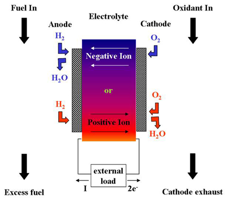
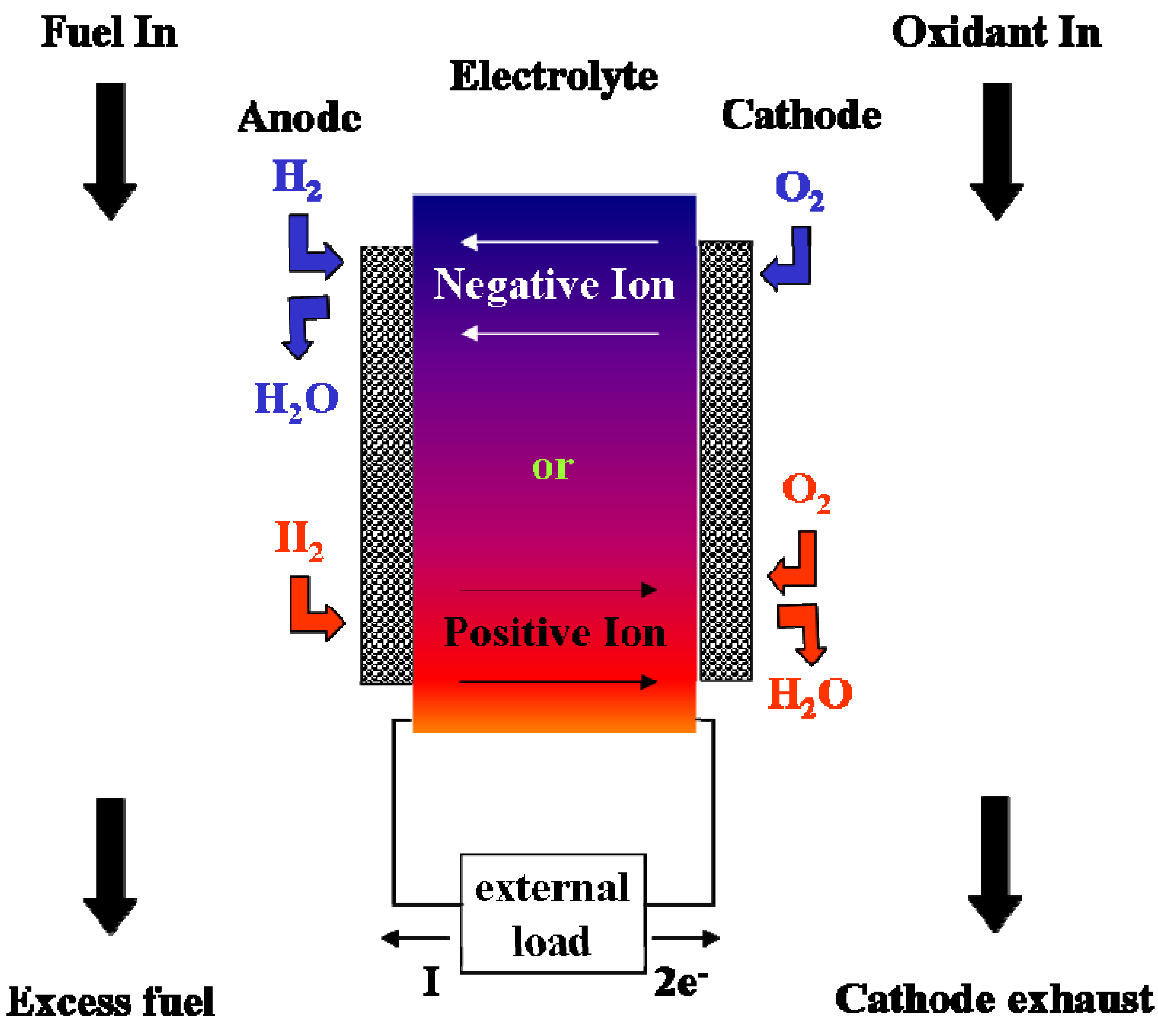
Fuel Cells (FCs) are electrochemical devices that convert the chemical energy of a reaction directly into electrical energy. The basic physical structure of a fuel cell consists of an electrolyte layer in contact with a porous anode and cathode on either side [1]. Figure 1 shows a schematic representation of a fuel cell with the reactant/product gases and the ion-conduction flow directions through the cell.
Contrary to batteries, fuel cells are not energy storage devices but electrical generators, i.e., the energy conversion process will theoretically remain unaltered as long as the fuel and oxidant feed the system. The fuel or oxidant flows through the anode or cathode, opposite the electrolyte, and generates electrical energy by the electrochemical oxidation of the fuel and the electrochemical reduction of the oxidant. Although the most common fuel and oxidant are hydrogen and oxygen, respectively, Appleby and Foulkes [2] have pointed out that, in theory, any substance capable of chemical oxidation (reduction) can be used as the fuel (oxidant) at the anode (cathode) of a fuel cell. Hydrogen has become the fuel of choice for most applications because of its high reactivity when suitable catalysts are used. However, a variety of fuels are today in different stages of development.
Figure 1.
Schematic of an individual fuel cell. In this general case, the electrolyte allows positive or negative ions to flow across it.
Figure 1.
Schematic of an individual fuel cell. In this general case, the electrolyte allows positive or negative ions to flow across it.

The operating temperature plays an important role in dictating the type of fuel that can be used in a fuel cell. Low-temperature FCs with aqueous electrolytes are, in most practical applications, restricted to hydrogen as a fuel (except for probably direct methanol fuel cells). On the contrary, hydrocarbons like CH4 can be directly used in high temperature fuel cells because of the rapid electrode kinetics and lesser-required catalytic activity at higher temperatures. In this type of fuel cells, the reforming reactions (conversion of hydrocarbon into hydrogen) can occur within the cell (internal reforming). Taking into account that hydrogen is not a natural resource but a synthetic and expensive energy carrier (as opposed to hydrocarbon fuels) a prominent role can be easily anticipated for hydrocarbon-based fuel cells in the near future. For the same reason, the external reformers have received special attention in recent years, in order to make possible the use of these fuels in the lower temperature cells. However, this item not only increases the complexity and the cost of the system, but also decreases the overall efficiency.
Apart from the fuel, the operating temperature dictates the physicochemical and thermomechanical properties of materials used in the fuel cell components (i.e., electrolyte, electrodes, interconnection materials, current collectors, etc). For instance, aqueous electrolytes are limited to temperatures of about 200 °C or lower due to a high water vapour pressure and rapid degradation at higher temperatures. Quite the opposite, the electrolytes for solid oxide fuel cells (SOFCs) require high temperatures to achieve the oxide-ion conductivity necessary to ensure high enough power density, with targets of 1 W/cm2. These high operating temperatures (over 800 °C) involve some problems, especially related to the materials compatibility. The origin of this limitation and possible solutions are the main goal of this review and will be discussed along different sections.
1.1. Effect of Low Operating Temperatures in Fuel Cell Efficiency
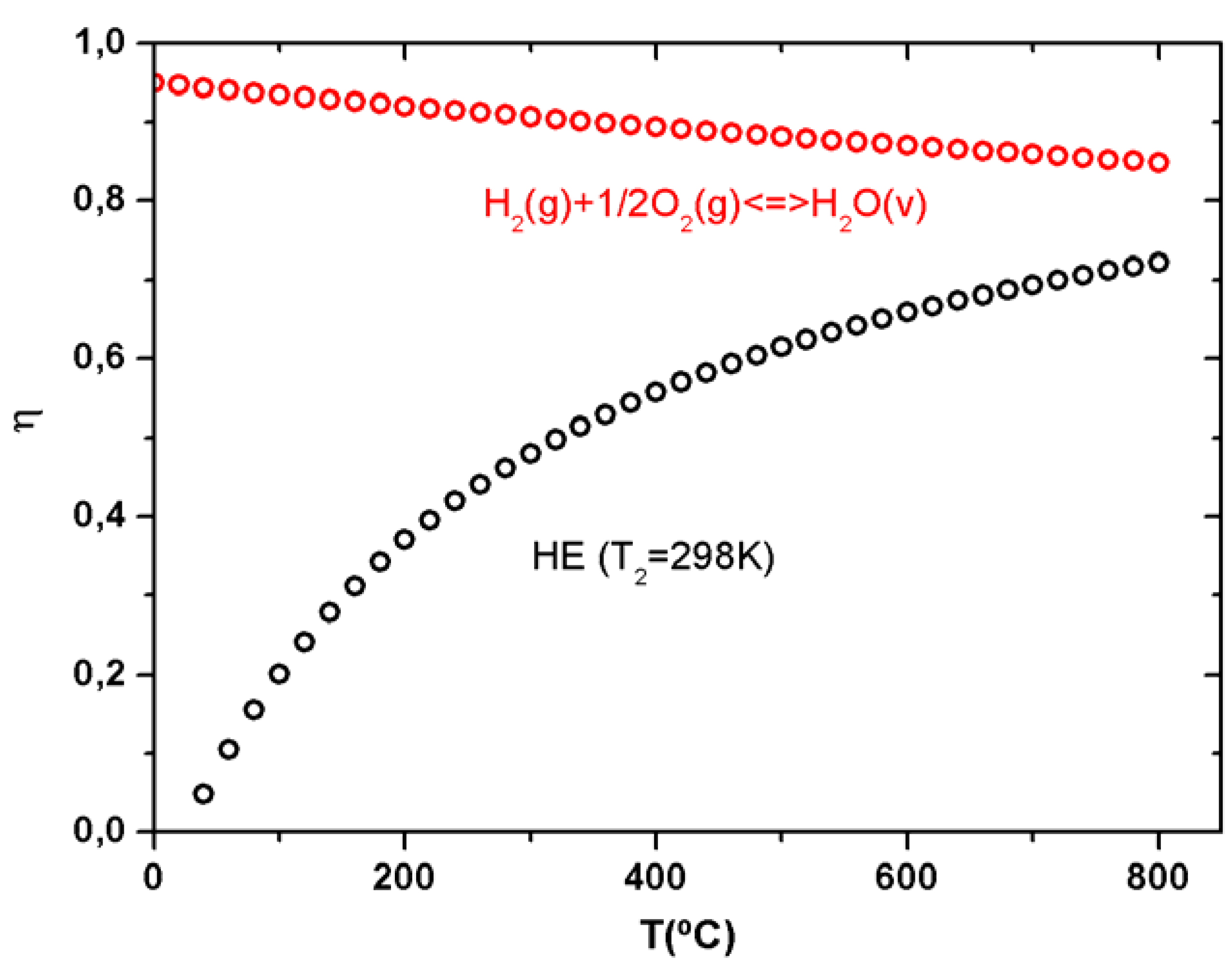
Before analysing any particular drawback or advantage of reducing the operating temperature in SOFCs, it is important to analyze the effect of the temperature on the efficiency for a more general fuel cell. For well-known heat engines, lower operation temperatures mean lower efficiencies; fortunately, fuel cells for their part have the opposite behaviour, i.e., the lower the temperature the higher the theoretical efficiency. Figure 2 shows a comparison between a heat engine working at a fixed cold source (room temperature) and a fuel cell based on hydrogen/oxygen. It clearly shows the effect of lowering the temperature for both devices, concluding the suitability of fuel cells to reduce the working temperature without losing efficiency (even increasing it slightly).
The theoretical thermodynamic derivation of Carnot Cycle shows that even under ideal conditions, a heat engine cannot convert all the heat energy supplied to it into mechanical energy. The maximum efficiency (1) only depends on the temperature of the thermal sources (T1 > T2), in such a way that, lowering the temperature of the hot source the efficiency diminishes.
On the contrary, in the case of an electrochemical converter the efficiency is defined as the amount of useful energy produced relative to the change in stored chemical energy that is released when a fuel is reacted with an oxidant, i.e., enthalpy increment, ΔH. The maximum electrical work obtainable in a fuel cell is given by the change in Gibbs free energy (ΔG) of the electrochemical reaction at the temperature and pressure of interest not being limited by the Carnot Cycle.
Figure 2.
Compared efficiency for a heat engine (black circles) and a fuel cell producing water vapour (red circles), as a function of temperature. The heat engine is supposed to work between a variable hot source and a fixed cold source at room temperature (T2 = 298K).
Figure 2.
Compared efficiency for a heat engine (black circles) and a fuel cell producing water vapour (red circles), as a function of temperature. The heat engine is supposed to work between a variable hot source and a fixed cold source at room temperature (T2 = 298K).
1.2. Solid Oxide Fuel Cells
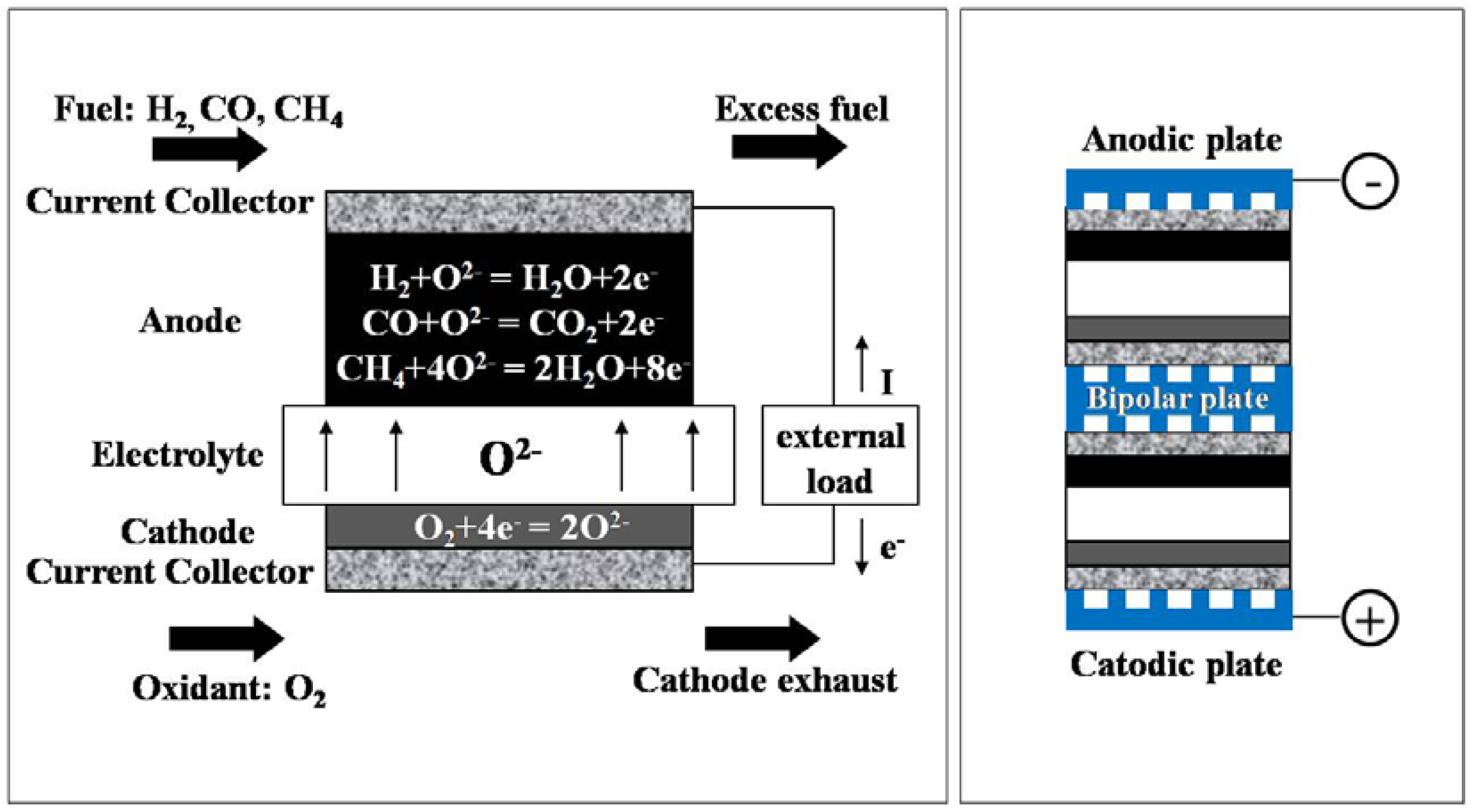
A Solid Oxide Fuel Cell (SOFC) is a particular type of fuel cell consisting of a gas tight solid electrolyte separating two electrodes, cathode and anode, exposed to two independent atmospheres of different oxygen partial pressure [3] (Figure 3). Electrolytes are ionically conducting oxides with an ionic transport number close to unity. Oxygen is reduced at the cathode/electrolyte interface and is incorporated to the electrolyte following the reaction:
O2 cathode + 4e− = 2O2−electrolyte
At the anode, the oxygen ions react to form different compound depending on the fuel gas present, e.g., H2O with H2 working as a fuel (Figure 3). The SOFC is therefore considered an electrochemical cell that generates an electromotive force (emf) given by the Nernst equation, see equation (3) for the particular case of H2 working as a fuel. This expression describes the system only in equilibrium conditions, i.e., without current flowing through the device. The actual voltage (V) under load (R) is usually lower due to the polarization losses associated with the cathode (ηc) and the anode (ηa) (4):
Figure 3.
Scheme and performance of a SOFC and SOFC stack operating with different fuel gases.
Minimising these losses is of fundamental importance in optimising devices and addressing materials properties such as exchange kinetics, transport properties and microstructure. SOFC performance is highly dictated by the ohmic loss of the electrolyte and the resistance due to the cathodic polarization. These drawbacks are magnified when diminishing the operation temperature because of the limitations of the materials properties at intermediate temperature regimes (600–800 °C). Nevertheless, a trade-off should be found because special features related to the high operating temperature of SOFCs make them very attractive for utility and industrial applications. Among others, the high operation temperature ensures that all fuel compositions, when combined with the necessary amount of water vapour, will oxidize rapidly and reach the thermodynamic equilibrium if sufficient air is provided to the cathode side. In addition, high temperatures increment the sulphur tolerance levels one or two orders of magnitude over than for other types of fuel cells. This permits the use of simpler high temperature sulphur removal methods, which are more efficient than the low temperature methods required for the other types.
2. The State-of-the-Art Materials for Solid Oxide Fuel Cells
The development of solid electrolyte fuel cells started with the work of F. Haber, who first patented a solid electrolyte fuel cell in 1905 [4]. As early as 1897, W. H. Nernst used yttrium-doped zirconia as the electrolyte for lamps of his invention, the so-called “Nernst-Lampe” [5]. However, it was not until 1943 that Wagner recognised the existence of vacancies in the anion sublattice of mixed oxide solid solutions and thus explained the conduction mechanism of the Nernst light [6]. Before this statement on the mechanism of conduction, Bauer and Preiss used zirconia ceramics for the first time in fuel cells [7]. By the late 1950s, researchers in the Netherlands, and the Consolidation Coal Company in Pennsylvania, and General Electric in New York were carrying out small-scale research into solid oxide fuel cells. In this development, solid electrolytes based on ZrO2 dominated immediately [8]. One company, Westinghouse Electric Corporation continued to develop tubular solid oxide fuel cells [9], and in 1962 one of the first US Federal research contracts by the newly-formed Office of Coal Research in the Department of the Interior was granted to Westinghouse to study a fuel cell again using zirconium oxide and calcium oxide.
The historical prominent role of stabilized zirconium oxide has been extended until today. Currently, yttrium stabilized zirconia (3, 8 or 10% yttria, abbreviated to YSZ) is the most common electrolyte for SOFC. YSZ provides high conductivity at temperatures above 800 °C while exhibiting negligible electronic conductivity at these temperatures (above 1,500 °C it becomes an electronic conductor) [10]. In addition, fully stabilized zirconia offers matching secondary requirements such as chemical stability with the other SOFC components or durability and good high-temperature mechanical properties [11].
Apart from YSZ used in the electrolyte, the common choice for the other cell components is strontium-doped lanthanum manganite (LSM) for the cathode, Ni-YSZ cermet for the anode and strontium-doped lanthanum chromite (LSC) for the interconnections. Table 1 shows the evolution of cell components for this prototype.

Table 1.
Evolution of cell components for tubular SOFCs (adapted from reference [1]).
| Component | ca. 1965 | ca. 1975 | At Present |
|---|---|---|---|
| Anode | Porous Pt | Ni/ZrO2 cermet | Ni/ZrO2 cermet (~150 μm thickness) 20%–40% porosity TEC~ 12.5 × 10⁻⁶ cm/cm K−1 |
| Cathode | Porous Pt | Stabilized ZrO2 impregnated with Pr2O3 and covered with SnO doped In2O3 | Doped LaMnO3 (~2 mm thickness) 30%–40% porosity TEC~ 11 × 10−6 cm/cm K−1 |
| Electrolyte | YSZ (~0.5-mm thickness) | YSZ | YSZ (~30–40 μm thickness) TEC~ 10.5 × 10⁻⁶ cm/cm K−1 |
| Interconnector | Pt | Mn doped cobalt chromite | Doped LaCrO3 (~100 μm thickness) TEC~ 10 × 10−6 cm/cm K−1 |
The strontium-doped lanthanum manganite system (La1-xSrxMnO3-δ, x = 0.10–0.20) is the typical choice for the cathode because of its stability under oxidising conditions (decomposition at 1,000 °C for pO2 < 10−14), its sufficient electrical conductivity at high temperatures (σ~102 S·cm−1 at 1,000 °C) and its thermal expansion. LSM matches to the YSZ electrolyte (TEC~11.1 × 10⁻⁶ cm/cm K−1). The strontium dopant does not increase the oxygen vacancy concentration but rather oxidises the manganese ion (Mn3+→Mn4+) increasing the electronic conduction produced by electron hopping. The electronic conductivity increases linearly with the Sr concentration (up to a maximum at 50 mol%) [12] but, for concentrations above 30 mol%, formation of isolating phases in reaction with the YSZ electrolyte is often observed at temperatures above 1,200 °C, e.g., La2Zr2O7 [13]. On the other hand, the absence of oxygen vacancies, i.e., anionic diffusion, makes difficult the oxygen reduction reaction at the ncathode/electrolyte interface (2) restricting this process to the three-phase boundary (TPB) regions, where the oxygen, cathode and electrolyte are in contact. The importance of this limitation is presently on controversy. Recent investigations by Maier and Fleig have pointed out that the ionic conductivity itself does not determine the active zone broadening [14,15]. The variation of this broadening depends on the surface exchange to ionic conductivity ratio in relation to the particle size.
The Ni-YSZ cermet was introduced in the sixties and seventies by Westinghouse Electric Corporation in order to take advantage of the good catalytic activity of Ni at the same time that improving the matching between the YSZ and the anode thermal expansion coefficients [9]. The presence of YSZ balances the thermal expansion coefficient of the Ni (TEC~ 18.3 × 10⁻⁶ cm/cm K−1) while inhibits the sintering of the metallic particles. This metal clustering is caused by the high operating temperatures and reduces the active area and percolation of the anode. Since YSZ is electronically insulating, the Ni phase in the cermet must be present in a high enough concentration to allow percolation, i.e., 40–60 vol% [16].
3. The Relevance of the Temperature for Solid Oxide Fuel Cells
In order to attain reasonable power density, current state-of-the-art SOFC systems are normally operated in the temperature regime of 850–1,000 °C. There are both beneficial and detrimental effects of reducing stack temperature. Primary drivers for lowering the operating temperature of SOFCs towards or below 850 °C are to get an optimum trade-off between performance and lifetime of the stack and to reduce the overall system cost. The most significant obstacle is that a set of fully compatible materials like those for high temperature have not been developed for operation in the intermediate range. The main effects of reducing the operating temperature are discussed below.
3.1. Thermo-Mechanical Mismatch
The thermal stress generated in a multilayer device with different TEC components often causes catastrophic failures. Majumdar et al. reported a detailed study about the stress and fracture behaviour of a three-layer ceramic SOFC developed at the Argonne National Lab [17]. They concluded that small differences in the TECs of different layers results in layer stresses and causes cracking parallel to the plane of the layers. This effect is clearly magnified under operation conditions because of the fatigue stresses caused by thermal cycling [18]. In order to reduce this thermal shock, large start-up periods are necessary. Intermediate temperature regimes would reduce both the stresses and the warm-up time to reach the operating temperature, which is a key parameter for the commercial implementation of SOFCs. Indeed, most recent developments have been related to bring the operating temperatures of SOFC down through materials improvement.
In the particular case of planar SOFCs, the problem of sealing is directly related to the difficulty of managing thermal stresses and geometrical tolerances at high temperatures. A sealing material has to match the SOFC’s TECs (TEC~9–12 × 10−6 cm/cm K−1) while maintaining a viscosity that is tolerant to thermal cycling (η~106–109 dPa·s) and sustaining a gas-tight seal in all the range of conditions. Still a high chemical stability is mandatory to resist the strongly oxidizing and reducing atmospheres present in SOFCs. Because of these stringent specifications, sealing remains a serious problem in the development of the SOFC. With the drive to lower operating temperatures (T < 800 °C), a wider range of sealant materials are available since the lower temperatures should reduce the stresses within the stack [19].
Another relevant issue is the capability of maintaining high specific surface areas at high temperatures due to coarsening and sintering processes. However, it is well-known the great interest in having high-specific surface areas when catalytic processes are involved. The possibility of a reduction of the working and fabrication temperatures opens fresh perspectives on the application of nanostructured materials in SOFCs.
3.2. Materials Stability
The effect of some negative thermally activated processes, which have a prominent role at high temperatures, would be also minimized lowering the temperature. Chromium vaporization from interconnectors, elemental interdiffusion and migration, metallic corrosion and ceramic aging effects are paradigmatic examples of these. For instance, a widely studied case of interdiffusion of elements in a multicomponent device is the previously mentioned formation of the La2Zr2O7 isolating phase on the YSZ/LaMnO3 interface. Kuscer et al. reported the formation of a 10 μm thickness La2Zr2O7 layer after 100 h at 1,450 °C because of the partial diffusion of manganese oxides into the YSZ [20]. Another example of thermally activated process is presented in the same work of Kuscer et al., they observed cathode layer separation along most of the La2Zr2O7/ LaMnO3 interface because of the segregation of manganese oxides. As thermally activated processes, ageing effects are amplified at higher temperatures.
The reducibility of certain oxides is also temperature dependent. To achieve good chemical stability at high temperatures could be therefore a limiting factor. Among the other ceramic components, the electrolyte and the interconnect materials are specially demanding because they have to maintain the electrical properties whereas exposed to both reducing and oxidizing atmospheres (pO2 1–10−15 atm). Then again, a temperature reduction would broaden the range of materials suitable for SOFC applications.
3.3. Thermal Management and Sulphur Tolerance
Another advantage of bringing down the operating temperature is the lesser loss of heat for the fuel cell stack. For similar levels of insulation, the heat loss is reduced at lower temperatures because the radiation (W) is directly proportional to the fourth power of the temperature, i.e., WαT4 (Stefen-Boltzmann’s Law). In addition, the balance of plant (BoP) should cost less if the stack fuel and oxidant exit temperature is less than 800 °C because of the demanding specifications required for the materials involved in the peripheral units. The BoP contains all the direct stacks support systems, reformers, compressors, pumps, and the recuperating heat exchangers. As a beneficial aspect of high temperatures, SOFCs operating at 1,000 °C have a cell exhaust temperature of approximately 815 °C after air preheating, so that it is possible to produce steam temperatures in excess of 540 °C, i.e., suitable for using it in a steam bottoming cycle. On the contrary, lower temperatures or small amounts of waste heat can only generate steam or hot water.
Let us outline now another mentioned aspect: the poisoning of the catalytic sites with sulphur. This effect is particularly important when there are nickel cermets, iron-containing components or noble metal catalysts such as typically found in fuel cells. However, at high temperatures the poisoning is minimized, e.g., planar SOFCs with ceramic components working at 1,000 °C can tolerate up to 3,000 ppm of sulphur. Elangovan et al. carried out a sulphur tolerance test on a SOFC loaded with 200 mA/cm2 at high temperature (900 °C) showing a good stability for 300 h of test under H2 atmosphere containing 500 ppm of H2S [21]. Therefore, if the suggested strategy of lowering operating temperatures is followed, special care should be taken to lower sulphur contents below 35 ppm1 in the used fuels.
3.4. Interconnect Materials (and Bipolar Plates)
It is important to notice the benefits of the temperature reduction for the cost reduction of the interconnect materials. Lowering the temperatures, there will allow a switch from ceramic to metallic interconnect. As well as the electrolyte, the interconnect material has to resist both reducing and oxidant atmospheres. Still it must have a good electronic conductivity (4–10 S·cm−1) and negligible ionic conductivity (<1% σelectrolyte). The high operating temperatures prevent most metals or alloys from being considered, and thus, the material of choice has traditionally been a ceramic based on the perovskite system LaCrO3 [19,22]. No other ceramic systems have been found to replace the presently used lanthanum chromite. There are many advantages to preparing the interconnection from a metallic material: higher electronic and thermal conductivity than the La-chromite, low-cost, easy manufacture and good workability. The ohmic losses in the metallic bipolar plate are small enough to be neglected. The excellent heat conduction allows the heat generated at the air electrode to be easily transported to the fuel electrode where the endothermic reforming reaction occurs (internal reforming) and eliminates the usage of cooling fluid that is usually excess air at cathode electrode. Ferritic stainless steels are the most promising alloys [23]. The main problem for metallic plates is the formation of an oxide scale on the cathode side, which introduces a high electrical resistance into the SOFC [19].
Another problem associated with the ferritic steels is the transport of Cr gaseous species [e.g., CrO3, CrO2(OH)2, Cr(OH)3] into the porous cathode and anode components and subsequent formation of deleterious phases such as MnCr2O4 and NiCr2O4, which can severely degrade the electrode performance [24]. At present, most developers are reducing the Cr activity by coating the steel with films of doped LaCrO3, but a reduction in operating temperature to below 700 °C is presented at the optimal solution [25]. Many development laboratories have reported good performance values for IT-SOFC stacks composed by: anode-supported thick film YSZ electrolytes, LSM-YSZ cathodes, and stainless steel bipolar plates. On the matter, the SOFC technology review driven by Blum et al. [26] is of particular interest.
4. Reduction of the Operation Temperature: Materials for Intermediate Temperature Solid Oxide Fuel Cells
As discussed in the previous section, the high operating temperature of the SOFCs puts numerous requirements on materials selection and on secondary units. These problems have limited the commercial development of SOFCs. Therefore, it is desirable to find solutions to reduce the fuel cell operating temperatures, i.e., in the range from 600 to 800 °C, while still maintaining the power densities achieved at high temperatures. Unfortunately, as the temperature diminishes, resistive losses across the solid electrolyte increase and overpotentials at the air and fuel electrode are similarly magnified. So far, different approaches to minimize resistive losses across the electrolyte have been adopted such as replacing the state-of-the-art yttria-stabilized zirconia by alternative solid electrolytes with higher ionic conductivity, using thinner solid electrolyte membranes and improving electrode materials.
4.1. Electrolyte Thickness Effect
With the development of thinner electrolytes, the supporting structure in a number of cell designs had to change, with the anode as the preferred choice for most. However, there are certain theoretical and practical limitations to the reduction in thickness that should be observed. Steele recently discussed the effect of electrolyte thickness on the surface exchange and diffusion coefficient of oxygen [27]. At a certain thickness, the surface exchange reaction (and not the diffusion of oxygen) becomes the rate-limiting step, and thus further reduction in thickness serves no benefit. This characteristic thickness (LC) at which the changeover from bulk to surface control occurs is shown to be equal to D*/k*, where D* (cm2·s−1) is the oxygen self-diffusion coefficient and k* (cm·s−1) the oxygen surface exchange coefficient in the oxide material [28]. Kilner pointed out that LC often has a value around 100 μm for most AO2 fluorite and many ABO3 perovskite oxide materials, which implies that fabricating membranes considerably less than 100 μm thick will not be advantageous unless the value of k* can be increased [29].
From a practical point of view, the technical challenge involves depositing pinhole- and crack-free dense layers of 5 to 50 µm in thickness on substrates of high porosity. The existence of defects leads to cross mixing of gases through the electrolyte and thereby lower the power density for the SOFC [30]. Several approaches to thin film fabrication have been reported including physical vapour deposition techniques [31], tape calendaring [30], sol-gel deposition [32], sputtering [33] or colloidal deposition [34]. Many of these approaches have allowed the fabrication of high quality films; however, the successful technique must be capable of scale-up for the mass market. At present it appears that the minimum thickness for dense impermeable films that can be reliably mass-produced, using relatively cheap ceramic fabrication routes, is around 10–15 µm [25]. Recent studies have shown the suitability of dense screen printing methods [35,36,37]. This technique combines the classical screen printing porous layer deposition [25] and the tape casting method [38] taking advantage of the cheapness, scalability and reduced thickness available with the first one and the full-density achievable by the tape casting method. In SOFC systems a target power density of 0.5 W·cm−2 for individual cell is often mentioned [25]. To obtain this power density with a high-performance fuel cell, e.g., 0.7 V at 0.7 A·cm−2, the total cell resistance (RTotal = Relectrodes + Relectrolyte) should not exceed about 0.45 Ω cm2, i.e., Relectrolyte = 0.15 Ω·cm2. Using the ionic conductivity-reciprocal temperature relationships for selected ceramic electrolytes [25], it becomes easy to calculate the maximum allowable thickness for a given conductivity value. For YSZ-based SOFCs, the ionic conductivity target is attained at around 700 °C for the 10–15 µm previously mentioned mass-production reliable thickness. Given the proven reliability of zirconia-based electrolytes in long-term SOFC tests [26], the use of YSZ electrolytes in reduced temperature fuel cells seems to be a logical choice although it is unlikely that YSZ-based systems will operate below this 700 °C because the intrinsic resistance of the material becomes too high.
4.2. Oxide Ion Conductors Limitations
Instead of reducing the thickness of the electrolyte, another strategy to reduce the SOFC’s operating temperature would be to develop new materials with a higher oxygen ion-conductivity compared to the state-of-the-art YSZ. However, among other solid-state devices, SOFCs impose the most stringent conditions for the electrolytes limiting the number of potential candidates. The porous nature of the cathode and anode exposes the SOFC electrolyte to both oxidising and reducing conditions during operation (pO2 1–10−15 atm). Therefore, the electrolyte requires a material with high chemical stability to keep an ideal pure ionic conduction over the wide range of oxygen partial pressures and high temperatures. In addition, the electrolyte must be an electrical insulator because significant electronic conduction in SOFC electrolyte may cause partial short-circuit and the subsequent dramatic loss of cell efficiency.
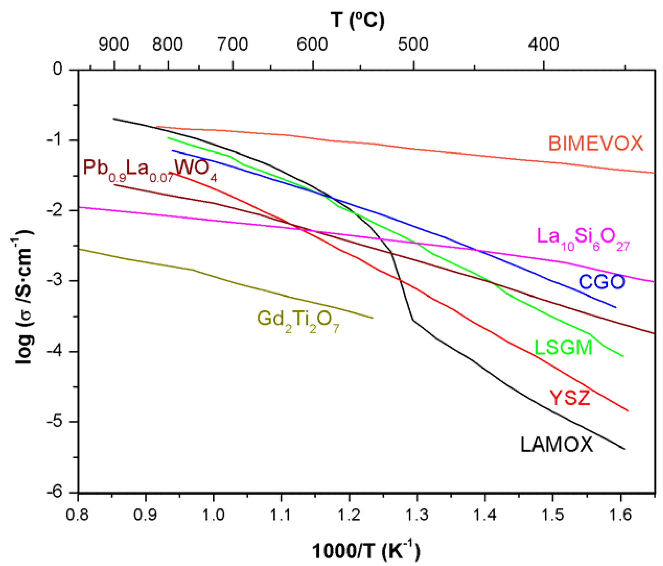
Figure 4.
Conductivity dependence on inverse of temperature for different oxide ionic conductors.

Some crystallographic families have shown high oxide-ion mobility [39,40]: fluorites (e.g., stabilised zirconia, doped ceria or δ-Bi2O3), oxygen-deficient perovskites (e.g., doped LaGaO3), aurivillius (e.g., Bi2MexV1-xO5.5-δ-BIMEVOX), pyrochlores (e.g., Gd2(Ti1-xZrx)O6O’), apatites (e.g., Ln10(SiO4)6O3) [41] or scheelites (AMoO4) [42]. Figure 4 shows the conductivity for representative compounds of these families.
Although the figure presents different alternatives to YSZ for lower temperatures in terms of conductivity, not fully satisfactory compounds have been established for medium temperatures (600–800 °C) in reducing atmospheres [40]. As an example, the new family of fast oxide-ion conductors based on La2Mo2O9 (LAMOX family), recently reported by Lacorre et al. [43], shows high enough conductivity at intermediate temperatures but stability problems under operating conditions [44,45,46] pushed this family into the background.
The small number of known materials with high oxide-ion mobility is due to the strong interaction between the oxide mobile species and the host cation network. The reason for this lies behind the big size of the oxide ion (r = 1.40 Å) and its double-charged nature. Although not discussed in the present work, SOFCs based on proton conducting electrolytes, instead of oxide ionic conductors, are of particular interest because they constitute a promising alternative at the intermediate-to-low range of temperatures still far from being introduced into commercial SOFCs because of stability problems and still low performances. For a detailed discussion on the applicability of proton conducting materials in SOFC refer to [47] and [48].
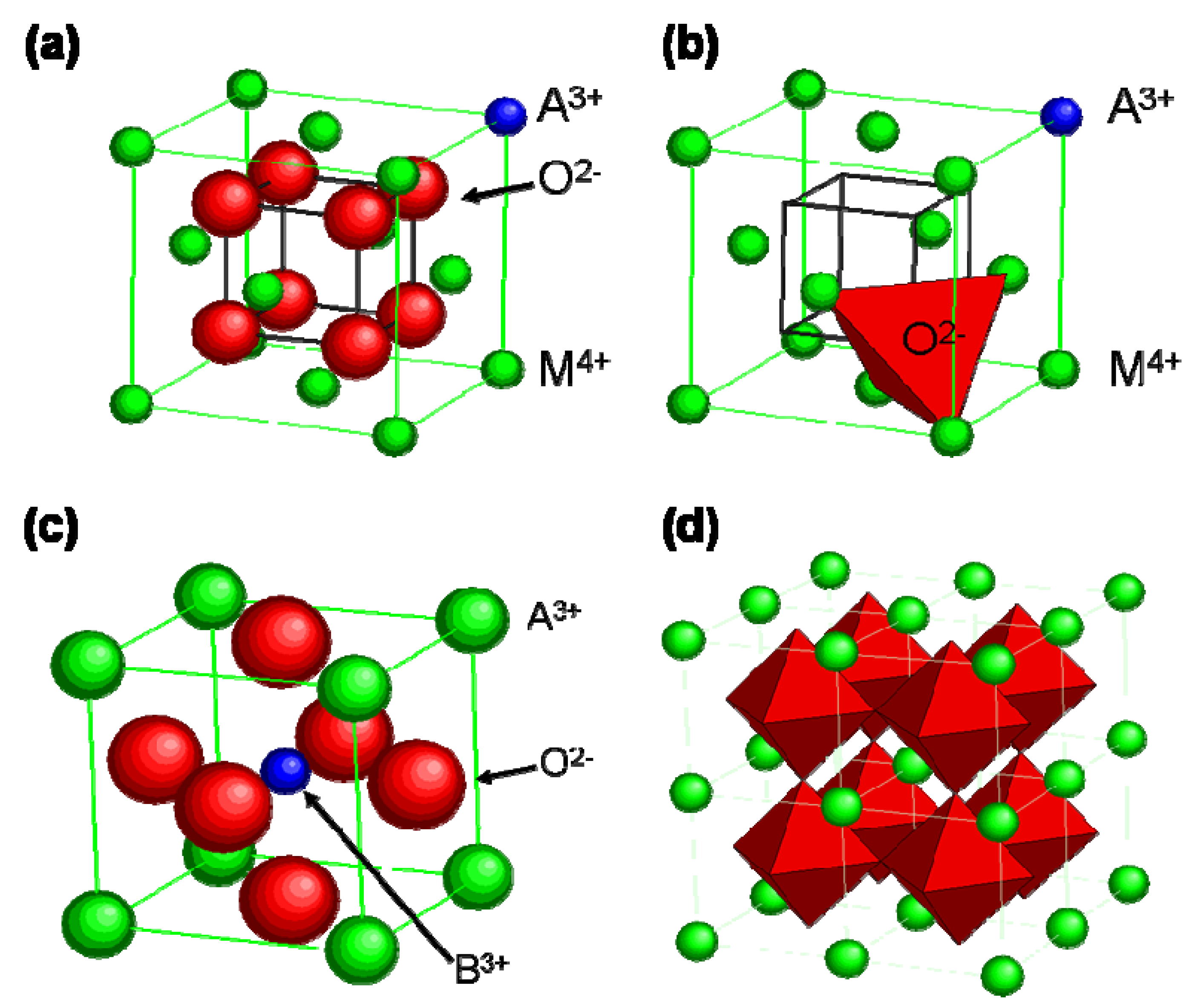
Coming back again to the oxide ionic conductors, very specific structural features have to be achieved in order to obtain a high mobility of such a species (see Figure 5) [49]. Although big efforts have been done, comprehensive knowledge of the diffusion mechanisms, even in simple structures like fluorites or perovskites, has not been reached yet. In addition, the high temperature necessary for the ionic conduction makes more difficult to analyze local structures from an experimental point of view. It is for this reasons that computer modelling has become a popular way to understand the disorder associated with fast ionic conductors [50].
Figure 5.
Sketches of the crystallographic structure of the most important oxide ionic conductors. Doped oxide fluorite structure with (a) the host metallic cation (M) in green, the aliovalent dopant (A) in blue and the oxygen (O) in red; (b) tetrahedral site for the oxide ion. Ideal perovskite type structure ABO3 (c) unit cell and (d) corner-shared BO6/2 octahedra in a cubic array with A cation at the body center position.
4.3. The Role of the Electrodes
The SOFC anode is very catalytically active towards the hydrogen and hydrocarbon oxidation reaction but suffers stability issues at high temperature and reducing atmospheres [54]. Under these conditions some anodes, e.g., Ni cermets, suffers carbon deposition due to the dehydrogenation of hydrocarbons. To overcome this problem, copper-based cermets have been proposed although the lower catalytic activity of Cu compared to Ni and stability issues working with YSZ increase the polarization resistance of the cell [55,56,57]. Another problem related to high operating temperatures is the sintering of nickel particles that reduces the catalytically active area. Mixed-conducting ceramics are one of the most promising alternatives to Ni-based anodes to improve their stability. They have the additional advantage that the charge transfer reaction may occur over the entire electrode/gas interface. The difficulty lies in finding a material that has the catalytic activity for hydrogen oxidation comparable to Ni or Cu. Several mixed-conducting ceramics have been investigated such as ZrO2/TiO2/Y2O3 systems [58], doped LaCrO3 [59] or La, Fe and Y doped SrTiO3 [60,61].
The fuel flexibility and the possibility of direct utilization of natural gas represent one of the major advantages of solid oxide fuel cell technology. In order to maintain this advantage and to overcome problems arising from the high operation temperature, novel anodes with high catalytic activity to different fuels in the intermediate temperature regime are required. A large number of materials have been considered, Lashtabeg and Skinner emphasized in a recent review [54] the importance of Ni/Sm0.15Ce0.85O2-δ, Ir/Ce0.9Gd0.1O2-x, trimetal FexCo0.5-xNi0.5/Sm0.2Ce0.8O1.9, Ni/Ca(Fe)TiO3 and Ru/YSZ among others.
Since the oxygen reduction reaction produced at the cathode has a high activation energy (often >1.5 eV), the decreasing temperature converts the cathode into the major source of electrical losses for the whole system as extensively reviewed, for instance, by Fleig [14]. Significant effort has been recently devoted to improving the poor catalytic activity of the traditional cathode materials obtaining excellent results [62,63].
In terms of the cathode performance, see Equation (2), a high rate for the reduction of oxygen molecules is required. As previously stated, the former reaction needs the direct involvement of gas-phase species at the electrochemical gas/electrode/electrolyte interface, i.e., the so-called three-phase boundary (TPB). The TPB active region is increased over a finite electrode thickness when using mixed ionic-electronic conductors (MIECs) due to their absorption of neutral oxygen. As shown by Adler et al. [64,65] , the characteristic active depth for the O2 reduction reaction in porous MIEC electrodes is limited by surface chemical exchange and solid state diffusion. Therefore, in addition to a high electronic conductivity, the cathode performance strongly depends on the oxygen chemical diffusion coefficient (D*) and the surface exchange rate (k*). Perovskite-type mixed ionic-electronic conductors such as doped LaCoO3, BaCoO3 or LaFeO3 have been extensively studied as possible cathodes in SOFCs [25,62,64].
Several recent studies have highlighted the potential of layered materials such as those of the Ruddlesden-Popper series [66,67,68,69,70] or the double perovskites [71,72,73,74,75,76,77]for cathode applications (see Table 2 for comparison of some layered and conventional cathodes). The anisotropy of oxygen diffusion and the presence of cation ordered structures seems to improve the oxygen transport properties compared to non-ordered compounds, resulting in lower activation energies and excellent oxygen surface exchange properties, which turn these materials into suitable cathodes for operation at SOFC reduced temperatures. Therefore, intrinsic properties of layered MIECs represents alternative to conventional simple cubic perovskite based MIEC cathode materials based on non stoichiometric defect structures.
Table 2.
Comparison of different values of oxygen transport properties and overall conductivity between ordered and non-ordered oxides for cathode applications in SOFCs.
| D*/cm2s–1 T = 500 °C | k*/cm·s–1 T = 500 °C | s/Scm–1 T = 500–750 °C | Ref. | |
|---|---|---|---|---|
| La0.8Sr0.2MnO3–δ | 4.5 × 10⁻²⁰ | 3.1 × 10⁻¹¹ | 120–130 | [ 78–80] |
| La0.8Sr0.2CoO3–δ | 9.0 × 10⁻¹⁴ | 2.8 × 10⁻⁹ | 1,500–1,600 | [ 78,79,81] |
| La0.5Sr0.5CoO3–δ | 1.5 × 10⁻¹⁰ | 3.9 × 10⁻⁷ | 1,300–1,800 | [ 78,79,81] |
| Ba0.5Sr0.5Co0.8Fe0.2O3–δ | 1.2 × 10⁻⁷ | 1.1 × 10⁻⁶ | 10–55 | [ 82,83] |
| La2NiO4+δ* | 3.3 × 10⁻⁹ | 7.0 × 10⁻⁹ | 55–65 | [ 67,84] |
| La2CoO4+δ* | 2.5 × 10⁻⁸ | 3.2 × 10⁻⁶ | 1–5 | [ 66,85] |
| GdBaCo2O5+δ* | 2.8 × 10⁻¹⁰ | 7.5 × 10⁻⁸ | 550–925 | [ 74,86] |
| PrBaCo2O5+δ* | 3.6 × 10⁻⁷ | 6.9 × 10⁻⁵ | 400–700 | [ 87] |
| *Layered o × ide structures | ||||
5. New Strategies for Operation Temperature Reduction Based on Micro and Nanotechnologies
Miniaturization of SOFCs by both reduction of electrolyte thickness and integration into Micro Electro Mechanical Systems (MEMS) can potentially reduce the operating temperature, partially solving the high-temperature associated problems. As previously mentioned, strictly concerning the electrolyte contribution to the total resistance of the device, the reduction of the electrolyte thickness down to 50–250 nm theoretically lowers the operating temperature of the electrolyte to the range of 300–600 °C. Moreover, the integration of SOFCs into MEMS allows the fabrication of low thermal mass structures, reducing the thermal response (warm-up and cycling periods of time) and lowering the energy consumption. These two points are of particular relevance for portable applications. Recent successful experiences in integrating SOFCs have triggered increasing interest in this field [87,88,89], moreover showing the potentiality of micro SOFC for covering classical problems related to Microsystems powering. In order to fully introduce SOFC into silicon based technology, big efforts have to be made to improve both integrability and compatibility [90,91].
Recent advances in engineering ionic-electronic transport using nanoionic materials have shown the big potential of ionic conductors in the form of thin films and nanocrystalline structures [92,93,94,95,96,97,98]. Due to space charge effects and/or local strain fields, conductivity at or near the interface can be modified increasing several orders of magnitude [99,100,101] or even changing its nature, e.g., from pure ionic to mixed ionic-electronic [102,103]. The most striking example is the recently published colossal ionic conduction at interfaces of yttria-stabilized zirconia/strontium titanate epitaxial heterostructures [101]. Although charge carrier needs to be confirmed as oxygen, as pointed out by J. A. Kilner [104], the indications from this and other similar works based on multilayers of YSZ [99,105] are that the enhancement effect can be substantial. This oxide-ionic conduction enhancement combined with strategies for controlling the ratio of ionic-to-electronic contributions could be of great interest for developing artificial structures for cathode IT-SOFC applications. The future development of these artificial structures will be primarily driven by a number of factors, namely: (a) developing techniques for producing interface-dominated highly pure materials; (b) controlling space charge layers (heterogeneous doping, graded composition, ion beam irradiation, etc); (c) controlling local structural changes (lattice mismatch, phase transformation, etc).
6. Conclusions
Lowering operation temperature of solid oxide fuel cells has become a fundamental issue to fully commercialize this chemical-to-electrical energy converter. The diminishment of the operation temperature in SOFCs is essential for improving materials compatibility, reducing energy consumption and start-up time and extending the durability. In addition, it can be done without losing efficiency. In this review, different strategies for lowering operation temperature in SOFC have been discussed. In particular those related to the issues listed below:
- -
- Reduction of the electrolyte thickness by using new techniques like dense screen printing.
- -
- Development of new electrolyte materials, e.g., LAMOX, BIMEVOX or apatite families, and understanding of mass transport properties, where simulation work could play a main role.
- -
- Development of new anodes based on oxides to substitute classical cermets, e.g., La-SrTiO3 based materials.
- -
- Development of new cathodes presenting layered structures, e.g. La2NiO4+d and GdBaCo2O5+d.
- -
- Adaptation of the fabrication processes for using interconnections based on metals (metal supported SOFC).
- -
- New strategies based on micro- and nano-technolgies (micro-SOFC and nanoionics concepts).
All these strategies are ongoing and could yield a major breakthrough in the development of high reliable and durable solid oxide fuel cells working in the low-to-intermediate range of temperatures.
Acknowledgements
This investigation has been supported by the Spanish Ministry of Science and Education (TEC-2007-64669 and TEC-2008-03255-E projects) and the “Generalitat de Catalunya” (2009-SGR-228). Special thanks to Angela Garcia Sanz for fruitful discussions.
References and Notes
- Fuel Cell Handbook, 7th ed.; E.G.&G. Services for the U.S.; Department of Energy, National Technical Information Service: Springfield, VA, USA, 2004.
- Appleby, A.J.; Foulkes, F.R. Fuel Cell Handbook; Van Nostrand Reinhold: New York, NY, USA, 1989. [Google Scholar]
- Yamamoto, O. Solid oxide fuel cells: Fundamental aspects and prospects. Electrochim. Acta 2000, 45, 2423–2435. [Google Scholar] [CrossRef]
- Haber, F.; Moser, A. Das Generatorgas- und das Kohlenelement. Z. Elektrochem. 1905, 11, 593–609. [Google Scholar] [CrossRef]
- Nernst, W. Über die elektrolytische Leitung fester Körper bei sehr hohen Temperaturen. Z. Elektrochem. 1899, 6, 41–43. [Google Scholar]
- Wagner, C. Über den Mechanismus der elektrischen Stromleitung im Nernststift. Naturwissenschaften 1943, 31, 265–268. [Google Scholar] [CrossRef]
- Baur, E.; Preis, H. Über Brennsto-Ketten mit Festleitern. Z. Elktrochem 1937, 43, 727–732. [Google Scholar]
- Möbius, H.H. On the history of solid electrolyte fuel cells. J. Solid State Electrochem. 1997, 1, 2–16. [Google Scholar]
- Final Report, Project Fuel Cell, Rep. No. 57; Westinghouse Electric Corp: Monroeville, PA, USA, 1970.
- Etsell, T.H.; Flengas, S.N. The electrical properties of solid oxide electrolytes. Chem. Rev. 1970, 70, 339–376. [Google Scholar] [CrossRef]
- Terauchi, S.; Takizawa, H.; Endo, T.; Uchida, S.; Terui, T.; Shimada, M. High ionic conductivity and high fracture strength of cubic zirconia, (Y0.16- xScx)Zr0.84O1.92/alumina composites. Mat. Letts. 1995, 23, 273–275. [Google Scholar] [CrossRef]
- Li, Z.; Behruzi, M.; Fuerst, L.; Stöver, D. Crystalline structure and electrical conductivity of bulk-sintered and plasma-sprayed La1-xSrxMnO3-8 with 0 < x < 0.9. In Proceedings of the 3rd International Symposium of Solid Oxide Fuel Cells, Honolulu, HI, USA, May 1993; Singhal, S.C., Ed.; The Electrochemical Society: Pennington, NJ, USA, 1995; p. 171. [Google Scholar]
- Mitterdorfer, A.; Gauckler, L.J. La2Zr2O7 formation and oxygen reduction kinetics of the La0.85Sr0.15MnyO3, O2 (g)|YSZ system. Solid State Ionics 1998, 111, 185–218. [Google Scholar] [CrossRef]
- Fleig, J. Solid oxide fuel cell cathodes: Polarization mechanisms and modeling of the electrochemical performance. Ann. Rev. Mat. Res. 2003, 33, 361–382. [Google Scholar] [CrossRef]
- Fleig, J.; Maier, J. The polarization of mixed conducting SOFC cathodes: Effects of surface reaction coefficient, ionic conductivity and geometry. J. Eur. Ceram. Soc. 2004, 24, 1343–1347. [Google Scholar] [CrossRef]
- Dees, D.W.; Claar, T.D.; Easler, T.E.; Fee, D.C.; Mrazek, F.C. Conductivity of porous Ni/ZrO//2-Y//2O//3 cermets. J. Electrochem. Soc. 1987, 134, 2141–2146. [Google Scholar] [CrossRef]
- Majumdar, S.; Claar, T.; Flandermeyer, B. Stress and fracture behavior of monolithic fuel cell tapes. J. Am. Ceram. Soc. 1986, 69, 628–633. [Google Scholar] [CrossRef]
- Hsiao, Y.C.; Selman, J.R. The degradation of SOFC electrodes. Solid State Ionics 1997, 98, 33–38. [Google Scholar] [CrossRef]
- Ralph, J.M.; Schoeler, A.C.; Krumpelt, M. Materials for lower temperature solid oxide fuel cells. J. Mater. Sci. 2001, 36, 1161–1172. [Google Scholar] [CrossRef]
- Kuscer, D.; Holc, J.; Hrovat, M.; Bernik, S.; Samardzija, Z.; Kolar, D. Interactions between a thick film LaMnO3 cathode and YSZ SOFC electrolyte during high temperature ageing. Solid State Ionics 1995, 78, 79–85. [Google Scholar] [CrossRef]
- Elangovan, S.; Hartvigsen, J.; Khandkar, A.; Privette, R.M.; Kneidel, K.E.; Perna, M.A.; Rowley, D.R. Planar solid oxide fuel cell integrated system technology development. J. Power Sources 1998, 71, 354–360. [Google Scholar] [CrossRef]
- Nakamura, T.; Petzow, G.; Gauckler, L.J. Stability of the perovskite phase LaBO3 (B = V, Cr, Mn, Fe, Co, Ni) in reducing atmosphere I. Experimental results. Mater.Res. Bull. 1979, 14, 649–659. [Google Scholar]
- Zhu, W.Z.; Deevi, S.C. A review on the status of anode materials for solid oxide fuel cells. Mater. Sci. Eng. 2003, 227, 227–239. [Google Scholar] [CrossRef]
- Badwal, P.S.; Deller, R.; Foger, K.; Ramprakash, Y.; Zhang, J.P. Interaction between chromia forming alloy interconnects and air electrode of solid oxide fuel cells. Solid State Ionics 1997, 99, 297–310. [Google Scholar] [CrossRef]
- Brandon, N.P.; Skinner, S.J.; Steele, B.C.H. Recent advances in materials for fuel cells. Ann. Rev. Mat. Res. 2003, 33, 183–213. [Google Scholar] [CrossRef]
- Blum, L.; Meulenberg, W.A.; Nabielek, H.; Steinberger-Wilckens, R. Worldwide SOFC technology overview and benchmark. Int. J. Appl. Ceram. Technol. 2005, 2, 482–492. [Google Scholar] [CrossRef]
- Steele, B.C.H. Ceramic ion conducting membranes. Curr. Opin. Solid State Mater. Sci. 1996, 1, 684–691. [Google Scholar] [CrossRef]
- Steele, B.C.H. Interfacial reactions associated with ceramic ion transport membranes. Solid State Ionics 1995, 75, 157–165. [Google Scholar] [CrossRef]
- Kilner, J.A. Isotopic exchange in mixed and ionically conducting oxides. In Proceedings of the 2nd International Symposium. on Ionic and Mixed Conducting Ceramics, San Francisco, CA, USA, May 1994; Ramanarayanan, T.A., Worrell, W.L., Tuller, H.L., Eds.; Electrochemical Society: Pennington, NJ, USA, 1994; Vol. 94–12, p. 174. [Google Scholar]
- Minh, N.Q. Ceramic fuel cells. J. Am. Ceram. Soc. 1993, 76, 563–588. [Google Scholar] [CrossRef]
- Wang, L.S.; Barnett, S.A. Lowering the air-electrode interfacial resistance in medium-temperature solid oxide fuel cells. J. Electrochem. Soc. 1992, 139, L89–L91. [Google Scholar] [CrossRef]
- Kueper, T.W.; Visco, S.J.; de Jonghe, L.C. Thin-film ceramic electrolytes deposited on porous and non-porous substrates by sol-gel techniques. Solid State Ionics 1992, 52, 251–259. [Google Scholar] [CrossRef]
- Negishi, A.; Nozaki, K.; Ozawa, T. Thin-film technology for solid electrolyte fuel cells by the RF sputtering technique. Solid State Ionics 1981, 3, 443–446. [Google Scholar] [CrossRef]
- de Souza, S.; Visco, S.J.; De Jonghe, L.C. Thin-film solid oxide fuel cell with high performance at low-temperature. Solid State Ionics 1997, 98, 57–61. [Google Scholar] [CrossRef]
- Xia, C.; Chen, F.; Liu, M. Reduced-temperature solid oxide fuel cells fabricated by screen printing. Electr. Solid State Lett. 2001, 4, A52–A54. [Google Scholar] [CrossRef]
- Tarancón, A.; Dezanneau, G.; Arbiol, J.; Peiró, F.; Morante, J.R. Synthesis of nanocrystalline materials for SOFC applications by acrylamide polymerisation. J. Power Sources 2003, 118, 256–264. [Google Scholar] [CrossRef]
- Morata, A.; Tarancón, A.; Dezanneau, G.; Peiró, F.; Morante, J.R. Optimized screen-printing and SEM-FIB characterization of YSZ thin films for solid oxide fuel cells and gas sensors devices. Mater. Res. Soc. Symp. Proc. 2004, 822, 109–114. [Google Scholar] [CrossRef]
- Mistler, R.E.; Twiname, E.R. Tape Casting: Theory and Practice; The American Ceramic Society: Westerville, OH, USA, 2000. [Google Scholar]
- Boivin, J.C.; Mairesse, G. Recent material developments in fast oxide ion conductors. Chem. Mater. 1998, 10, 2870–2888. [Google Scholar] [CrossRef]
- Goodenough, J.B. Oxide-ion electrolytes. Annu. Rev. Mater. Res. 2003, 33, 91–128. [Google Scholar] [CrossRef]
- Zacate, M.; Minervini, L.; Bradfield, D.J.; Grimes, R.W.; Sickafus, K.E. Defect cluster formation in M2O3-doped cubic ZrO2. Solid State Ionics 2000, 128, 243–254. [Google Scholar] [CrossRef]
- Lu, T.; Steele, B.C.H. Electrical conductivity of polycrystalline BiVO4 samples having the scheelite structure. Solid State Ionics 1986, 21, 339–342. [Google Scholar] [CrossRef]
- Lacorre, P.; Goutenoire, F.; Bohnke, O.; Retoux, R.; Lagilant, Y. Designing fast oxide-ion conductors based on La2Mo2O9. Nature 2000, 404, 856–858. [Google Scholar] [CrossRef] [PubMed]
- Tarancón, A.; Norby, T.; Dezanneau, G.; Morata, A.; Peiró, F.; Morante, J.R. Conductivity dependence on oxygen partial pressure and oxide-ion transport numbers determination for La2Mo2O9. Electrochem. Solid-State Lett. 2004, 7, A373–A375. [Google Scholar] [CrossRef]
- Marrero-López, D.; Canales-Vázquez, J.; Ruiz-Morales, J.C.; Irvine, J.T.S.; Núñez, P. Electrical conductivity and redox stability of La2Mo2-xWxO9 materials. Electrochim. Acta 2005, 50, 4385–4395. [Google Scholar] [CrossRef]
- Marrero-López, D.; Peña-Martínez, J.; Ruiz-Morales, J.C.; Pérez-Coll, D.; Martín-Sedeño, M.C.; Núñez, P. Applicability of La2Mo2-xWxO9 materials as solid electrolyte for SOFCs. Solid State Ionics 2007, 178, 1366–1378. [Google Scholar] [CrossRef]
- Norby, T. The promise of protonics. Nature 2001, 410, 877–878. [Google Scholar] [CrossRef] [PubMed]
- Lefebvre-Joud, F.; Gauthier, G.; Mougin, J. Current status of proton-conducting solid oxide fuel cells development. J. Appl. Electrochem. 2009, 39, 535–543. [Google Scholar] [CrossRef]
- Boivin, J.C. Structural and electrochemical features of fast oxide ion conductors. Int. J. Inorg. Mater. 2001, 3, 1261–1266. [Google Scholar] [CrossRef]
- Keen, D.A. Disordering phenomena in superionic conductors. J. Phys. Condens. Matter. 2002, 14, R819–R857. [Google Scholar] [CrossRef]
- Minervini, L.; Zacate, M.; Grimes, R.W. Defect cluster formation in M2O3-doped CeO2. Solid State Ionics 1999, 116, 339–349. [Google Scholar] [CrossRef]
- Zacate, M.; Minervini, L.; Bradfield, D.J.; Grimes, R.W.; Sickafus, K.E. Defect cluster formation in M2O3-doped cubic ZrO2. Solid State Ionics 2000, 128, 243–254. [Google Scholar] [CrossRef]
- Kilo, M.; Argirusis, C.; Borchardta, G.; Jackson, R.A. Oxygen diffusion in yttria stabilised zirconia–Experimental results and molecular dynamics calculations. Phys. Chem. Chem. Phys. 2003, 5, 2219–2224. [Google Scholar] [CrossRef]
- Lashtabeg, A.; Skinner, S.J. Solid oxide fuel cells–A challenge for materials chemists? J. Mater. Chem. 2006, 16, 3161–3170. [Google Scholar] [CrossRef]
- Costa-Nunes, O.; Gorte, R.J.; Vohs, J.M. Comparison of the performance of Cu-CeO2-YSZ and Ni-YSZ composite SOFC anodes with H2, CO, and syngas. J. Power Sources 2005, 141, 241–249. [Google Scholar] [CrossRef]
- He, H.P.; Gorte, R.J.; Vohs, J.M. Highly sulfur tolerant Cu-ceria anodes for SOFCs. Electrochem. Solid-State Lett. 2005, 8, A279–A280. [Google Scholar] [CrossRef]
- Ruiz-Morales, J.C.; Canales-Vázquez, J.; Marrero-López, D.; Peña-Martínez, J.; Tarancón, A.; Irvine, J.T.S.; Núñez, P. Is YSZ stable in the presence of Cu? J. Mater. Chem. 2008, 18, 5072–5077. [Google Scholar] [CrossRef]
- Naito, H.; Arashi, H. Electrical properties of ZrO2-TiO2-Y2O3 system. Solid State Ionics 1992, 53, 436–441. [Google Scholar] [CrossRef]
- Sfeir, J. LaCrO3-based anodes: Stability considerations. J. Power Sources 2003, 118, 276–285. [Google Scholar] [CrossRef]
- Hui, S.; Petric, A. Evaluation of yttrium-doped SrTiO3 as an anode for solid oxide fuel cells. J. Eur. Ceram. Soc. 2002, 22, 1673–1681. [Google Scholar] [CrossRef]
- Ruiz-Morales, J.C.; Canales-Vázquez, J.; Savaniu, C.; Marrero-López, D.; Zhou, W.; Irvine, J.T.S. Disruption of extended defects in solid oxide fuel cell anodes for methane oxidatio. Nature 2006, 439, 568–571. [Google Scholar] [CrossRef] [PubMed]
- Skinner, S.J. Recent advances in perovskite-type materials for solid oxide fuel cell cathodes. Int. J. Inorg. Mater. 2001, 3, 113–121. [Google Scholar] [CrossRef]
- Shao, Z.; Haile, S.M.; Ahn, J.; Ronney, P.D.; Zhan, Z.; Barnett, S.A. A thermally self-sustained micro solid-oxide fuel-cell stack with high power density. Nature 2005, 435, 795–798. [Google Scholar] [CrossRef] [PubMed]
- Adler, S.B. Mechanism and kinetics of oxygen reduction on porous La1-xSrxCoO3-δ electrodes. Solid State Ionics 1998, 111, 125–134. [Google Scholar] [CrossRef]
- Adler, S.B.; Lane, J.A.; Steele, B.C.H. Electrode kinetics of porous mixed-conducting oxygen electrodes. J. Electrochem. Soc. 1996, 143, 3554–3564. [Google Scholar] [CrossRef]
- Munnings, C.N.; Skinner, S.J.; Amow, G.; Whitfield, P.S.; Davidson, I.J. Oxygen transport in the La2Ni1-xCoxO4+δ system. Solid State Ionics 2005, 176, 1895–1901. [Google Scholar] [CrossRef]
- Boehm, E.; Bassat, J.M.; Dordor, P.; Mauvy, F.; Grenier, J.C.; Stevens, P. Oxygen diffusion and transport properties in non-stoichiometric Ln2-xNiO4+δ oxides. Solid State Ionics 2005, 176, 2717–2725. [Google Scholar] [CrossRef]
- Boehm, E.; Bassat, J.M.; Dordor, P.; Mauvy, F.; Grenier, J.C. Oxygen transport properties of La2Ni1-xCuxO4+δ mixed conducting oxides. Solid State Sci. 2003, 5, 973–981. [Google Scholar] [CrossRef]
- Skinner, S.J.; Kilner, J.A. Oxygen diffusion and surface exchange in La2-xSrxNiO4+δ. Solid State Ionics 2000, 135, 709–712. [Google Scholar] [CrossRef]
- Burriel, M.; Garcia, G.; Santiso, J.; Kilner, J.A.; Chater, R.J.; Skinner, S.J. Anisotropic oxygen diffusion properties in epitaxial thin films of La2NiO4+δ. J. Mater. Chem. 2008, 18, 416–422. [Google Scholar] [CrossRef]
- Taskin, A.A.; Lavrov, A.N.; Ando, Y. Achieving fast oxygen diffusion in perovskites by cation ordering. Appl. Phys. Lett. 2005, 86, 1–3. [Google Scholar] [CrossRef]
- Taskin, A.A.; Lavrov, A.N.; Ando, Y. Transport and magnetic properties of GdBaCo2O5+x single crystals: A cobalt oxide with square-lattice Co O2 planes over a wide range of electron and hole doping. Phys. Rev. B 2005, 71, 1–28. [Google Scholar] [CrossRef]
- Chang, A.; Skinner, S.J.; Kilner, J.A. Electrical properties of GdBaCo2O5+x for ITSOFC applications. Solid State Ionics 2006, 177, 2009–2011. [Google Scholar] [CrossRef]
- Tarancón, A.; Skinner, S.J.; Kilner, J.A. yered perovskites as promising cathodes for Intermediate Temperature SOFCs. In Proceedings of the 7th European SOFC Forum, Lucerne, Switzerland, July 2006; Bossel, U., Ed.; The European Solid Oxide Fuel Cell Forum: Oberrohrdorf, Switzerland, 2006; pp. 78–88. [Google Scholar]
- Tarancón, A.; Skinner, S.J.; Chater, R.J.; Hernández-Ramírez, F.; Kilner, J.A. Layered perovskites as promising cathodes for intermediate temperature solid oxide fuel cells. J. Mater. Chem. 2007, 17, 3175–3181. [Google Scholar] [CrossRef]
- Kim, G.; Wang, S.; Jacobson, A.J.; Yuan, Z.; Donner, W.; Chen, C.L.; Reimus, L.; Brodersen, P.; Mims, C.A. Oxygen exchange kinetics of epitaxial PrBaCo2O5+x thin films. Appl. Phys. Lett. 2006, 88, 1–3. [Google Scholar]
- Kim, G.; Wang, S.; Jacobson, A.J.; Reimus, L.; Brodersen, P.; Mims, C.A. Rapid oxygen ion diffusion and surface exchange kinetics in PrBaCo2O5+x with a perovskite related structure and ordered a cations. J. Mater. Chem. 2007, 17, 2500–2505. [Google Scholar] [CrossRef]
- Bowmeester, H.J.M.; Burggraaf, A.J. Fundamentals of Inorganic Membrane Science and Technology; Burggraaf, A.J., Cot, L., Eds.; Elsevier: Amsterdam, The Netherlands, 1996; Volume 1, Chapter 10. [Google Scholar]
- Mauvy, F.; Bassat, J.M.; Boehm, E.; Dordor, P.; Grenier, J.C.; Loup, J.P. Chemical oxygen diffusion coefficient measurement by conductivity relaxation-correlation between tracer diffusion coefficient and chemical diffusion coefficient. J. Eur. Ceram. Soc. 2004, 24, 1265–1269. [Google Scholar] [CrossRef]
- Ahlgren, E.O.; Poulsen, F.W. Thermoelectric power and electrical conductivity of strontium-doped lanthanum manganite. Solid State Ionics 1996, 86, 1173–1178. [Google Scholar] [CrossRef]
- Petric, A.; Huang, P.; Tietz, F. Evaluation of La-Sr-Co-Fe-O perovskites for solid oxide fuel cells and gas separation membranes. Solid State Ionics 2000, 135, 719–725. [Google Scholar] [CrossRef]
- Wang, L.; Merkle, R.; Maier, J.; Acartürk, T.; Starke, U. Oxygen tracer diffusion in dense Ba0.5Sr0.5Co0.8Fe0.2O3-δ films. Appl. Phys. Lett. 2009, 94, 1–3. [Google Scholar]
- Peña-Martínez, J.; Tarancón, A.; Marrero-López, D.; Ruiz-Morales, J.C.; Núñez, P. Evaluation of GdBaCo2O5+x as cathode material for doped lanthanum gallate electrolyte IT-SOFCs. Fuel Cells 2008, 5, 351–359. [Google Scholar]
- Sayers, R.; De Souza, R.A.; Kilner, J.A.; Skinner, S.J. Low temperature diffusion and oxygen stoichimoetry in lanthanum nickelate. Solid State Ionics 2009, in press. [Google Scholar]
- Matsuura, T.; Tabuchi, J.; Mizusaki, J.; Yamamuchi, S.; Fueki, K. Electrical properties of La2-xSrxCoO4-δ: Structure, electrical conductivity, and Seebeck coefficient of single crystals x = 0.0, 0.5, 1.0 and 1.5. J. Phys. Chem. Solids 1988, 49, 1403–1408. [Google Scholar] [CrossRef]
- Tarancón, A.; Marrero-López, D.; Peña-Martínez, J.; Ruiz-Morales, J.C.; Núñez, P. Effect of phase transition on high-temperature electrical properties of GdBaCo2O5+x layered perovskite. Solid State Ionics 2008, 179, 611–618. [Google Scholar] [CrossRef]
- Evans, A.; Bieberle-Hütter, A.; Rupp, J.L.M.; Gauckler, L.J. J. Power Sources 2009, 194, 119. [CrossRef]
- Bieberle-Hutter, A.; Beckel, D.; Infortuna, A.; Muecke, U.P.; Rupp, J.L.M.; Gauckler, L.J.; Rey-Mermet, S.; Muralt, P.; Bieri, M.R.; Hotz, N.; Stutz, M.J.; Poulikakos, D.; Heeb, P.; Müller, P.; Bernard, A.; Gmür, R.; Hocker, T. Review on microfabricated micro-solid oxide fuel cell membranes. J. Power Sources 2008, 177, 123–129. [Google Scholar] [CrossRef]
- Huang, H.; Nakamura, M.; Su, P.; Fasching, R.; Saito, Y.; Prinz, F.B. High-performance ultrathin solid oxide fuel cells for low-temperature operation. J. Electrochem. Soc. 2007, 154, 20–24. [Google Scholar] [CrossRef]
- Tarancón, A.; Sabaté, N.; Cavallaro, A.; Gràcia, I.; Roqueta, J.; Garbayo, I.; Esquivel, J.P.; Garcia, G.; Cané, C.; Santiso, J. Residual stress of free-standing membranes of yttria-stabilized zirconia for micro solid oxide fuel cell applications. J. Nanosci. Nanotechnol. 2010, 10, 1. [Google Scholar] [CrossRef]
- Garbayo, I.; Tarancón, A.; Santiso, J.; Peiró, F.; Alarcón-LLadó, E.; Cavallaro, A.; Gràcia, I.; Cané, C.; Sabaté, N. Electrical characterization of thermomechanically stable YSZ membranes for micro Solid Oxide Fuel Cells applications. Solid State Ionics 2009. submitted. [Google Scholar] [CrossRef]
- Maier, J. Nanoionics: Ion transport and electrochemical storage in confined systems. Nat. Mater. 2005, 4, 805–815. [Google Scholar] [CrossRef] [PubMed]
- Maier, J. Thermodynamic aspects and morphology of nano-structured ion conductors: Aspects of nano-ionics Part I. Solid State Ionics 2002, 154, 291–301. [Google Scholar] [CrossRef]
- Maier, J. Defect chemistry and ion transport in nanostructured materials: Part II. Aspects of nanoionics. Solid State Ionics 2003, 157, 327–334. [Google Scholar] [CrossRef]
- Maier, J. Nano-sized mixed conductors (Aspects of nano-ionics. Part III). Solid State Ionics 2002, 148, 367–374. [Google Scholar] [CrossRef]
- Maier, J. Ionic transport in nano-sized systems. Solid State Ionics 2004, 175, 7–12. [Google Scholar] [CrossRef]
- Tuller, H.L. Ionic conduction in nanocrystalline materials. Solid State Ionics 2000, 131, 143–157. [Google Scholar] [CrossRef]
- Van de Krol, R.; Tuller, H.L. Electroceramics-The role of interfaces. Solid State Ionics 2002, 150, 167–179. [Google Scholar] [CrossRef]
- Kosacki, I.; Rouleau, C.M.; Becher, P.F.; Bentley, J.; Lowndes, D.H. Surface/interface-related conductivity in nanometer thick YSZ films. Electrochem. Solid-State Lett. 2004, 7, A459–A461. [Google Scholar] [CrossRef]
- Kosacki, I.; Rouleau, C.M.; Becher, P.F.; Bentley, J.; Lowndes, D.H. Nanoscale effects on the ionic conductivity in highly textured YSZ thin films. Solid State Ionics 2005, 176, 1319–1326. [Google Scholar] [CrossRef]
- Garcia-Barriocanal, J.; Rivera-Calzada, A.; Varela, M.; Sefrioui, Z.; Iborra, E.; Leon, C.; Pennycook, S.J.; Santamaría, J. Colossal ionic conductivity at interfaces of epitaxial ZrO2:Y2O3/SrTiO3 heterostructures. Science 2008, 321, 676–680. [Google Scholar] [CrossRef] [PubMed]
- Chiang, Y.M.; Lavik, E.B.; Kosacki, I.; Tuller, H.L.; Ying, J.Y. Nonstoichiometry and electrical conductivity of nanocrystalline CeO2-x. J. Electroceram. 1997, 1, 7–14. [Google Scholar] [CrossRef]
- Tschope, A.; Birringer, R. Grain size dependence of electrical conductivity in polycrystalline cerium oxide. J. Electroceram. 2001, 7, 169–177. [Google Scholar] [CrossRef]
- Kilner, J.A. Ionic conductors: Feel the strain. Nat. Mater. 2008, 7, 838–839. [Google Scholar] [CrossRef] [PubMed]
- Peters, A.; Korte, C.; Hesse, D.; Zakharov, N.; Janek, J. Ionic conductivity and activation energy for oxygen ion transport in superlattices-The multilayer system CSZ (ZrO2 + CaO) / Al2O3. Solid State Ionics 2007, 178, 67–76. [Google Scholar] [CrossRef]
- Korte, C.; Peters, A.; Janek, J.; Hesse, D.; Zakharov, N. Ionic conductivity and activation energy for oxygen ion transport in superlattices-The semicoherent multilayer system YSZ (ZrO2 + 9.5 mol% Y2O3)/Y2O3. Phys. Chem. Chem. Phys. 2008, 10, 4623–4635. [Google Scholar] [CrossRef] [PubMed]
© 2009 by the authors; licensee Molecular Diversity Preservation International, Basel, Switzerland. This article is an open-access article distributed under the terms and conditions of the Creative Commons Attribution license (http://creativecommons.org/licenses/by/3.0/).
Share and Cite
MDPI and ACS Style
Tarancón, A. Strategies for Lowering Solid Oxide Fuel Cells Operating Temperature. Energies 2009, 2, 1130-1150. https://doi.org/10.3390/en20401130
AMA Style
Tarancón A. Strategies for Lowering Solid Oxide Fuel Cells Operating Temperature. Energies. 2009; 2(4):1130-1150. https://doi.org/10.3390/en20401130
Chicago/Turabian StyleTarancón, Albert. 2009. "Strategies for Lowering Solid Oxide Fuel Cells Operating Temperature" Energies 2, no. 4: 1130-1150. https://doi.org/10.3390/en20401130