2. Results and Discussion
Our previous experimental results indicated that the majority of charges are transferred via mediators, even when the RC is attached to an electrode [
8]. In this paper, we introduce a new and simple approach to achieve good absorption, by dissolving the RCs in an electrolyte, and allowing mediators to transport charges between the RC and the electrodes. The key to success of this approach is to use electrodes that have a different ratio of kinetic rates for the two mediators, so oxidation is favored on one side, and reduction on the other. In this configuration the photocurrent is enhanced by increasing the concentration of the RC in the electrolyte.
The RC of the photosynthetic bacterium
Rhodobacter sphaeroides has been used by a number of groups in photovoltaic device experiments, in part because of its stability [
7,
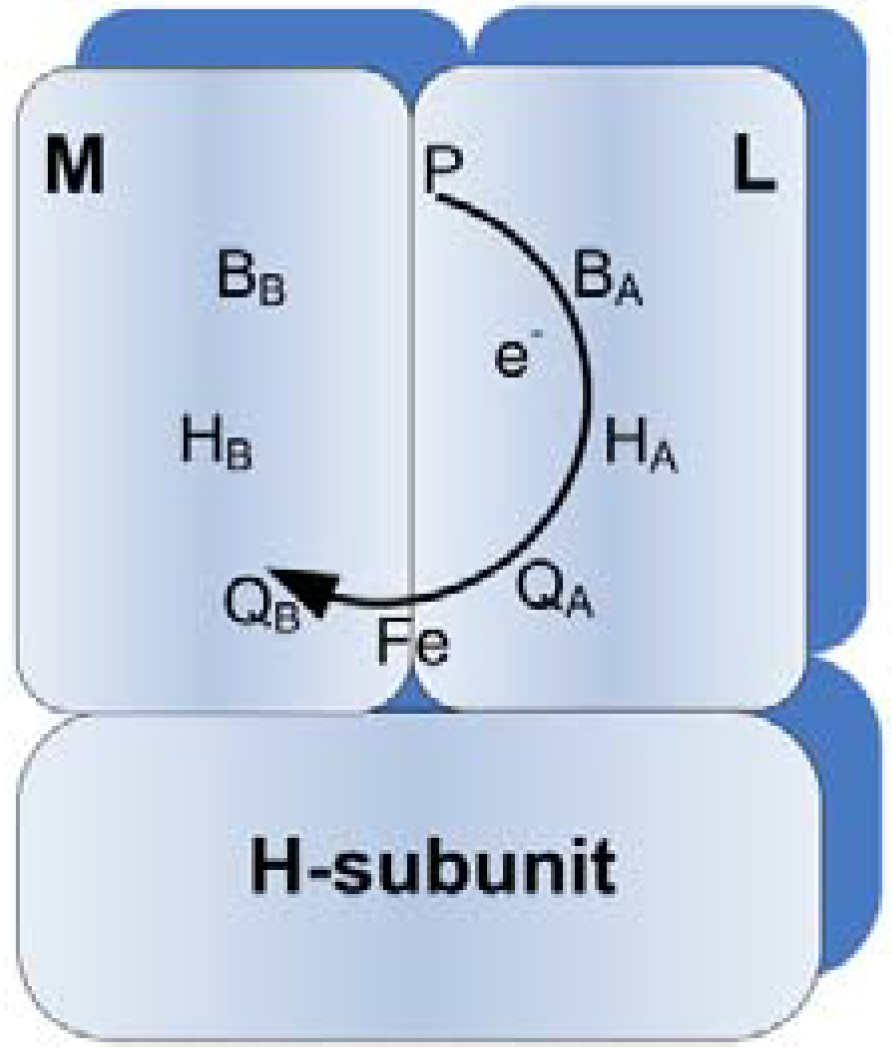
9]. This RC is an integral membrane protein that contains three subunits, L, M and H, and electron transfer cofactors. Subunits L and M are arranged in two-fold symmetry, and the H subunit binds to both L and M [
10]. The cofactors, where the energy conversion takes place, include the primary electron donor (P) which is a bacteriochlorophyll dimer, two bacteriochlorophylls (B
A and B
B), two bacteriopheophytins (H
A and H
B), two quinones (Q
A and Q
B), and one iron atom (Fe
2+), as depicted in
Figure 1. Cofactors are all non-covalently bound to the protein subunits.
Figure 1.
Representation of the photosynthetic reaction center of Rhodobacter sphaeroides. M, L and H represent protein subunits, whereas other symbols indicate cofactors. The arrow shows the path of electron transfer from P to QB when the RC is illuminated.
Figure 1.
Representation of the photosynthetic reaction center of Rhodobacter sphaeroides. M, L and H represent protein subunits, whereas other symbols indicate cofactors. The arrow shows the path of electron transfer from P to QB when the RC is illuminated.
When a photon is absorbed, P is raised to an excited state (P*), and in about 100 μs the excited electron is transferred to Q
B through the path indicated in
Figure 1. The developed dipole across the RC is very stable and has a relaxation time of on the order of one second [
10]. The separated charges can be removed from the RC by mediators, which in our experiments reported here, were ferrocene (Cp
2Fe) and methyl viologen (MV
2+) [
11,
12]. In these reactions Cp
2Fe donates an electron to the P side of the RC and converts to Cp
2Fe
+, whereas MV
2+ is reduced to MV
+ when an electron is removed from Q
B side [
13]. The reactions that occur at the RC are:
Since the redox reaction rates of mediators are much faster than the rate of recombination in the RC, the charges are transferred to the mediators before they recombine. However, recombination can also occur through interaction between the photoactivated mediators (Cp
2Fe
+ and MV
+) to convert them back to Cp
2Fe and MV
2+:
In a solution containing the RC and the mediators, the concentrations of Cp2Fe+ and MV+ increase with time upon illumination. The increase in the concentration results in a faster reaction rate for reaction (3) until the rate reaches what we call the generation rate, G, resulting in a steady state.
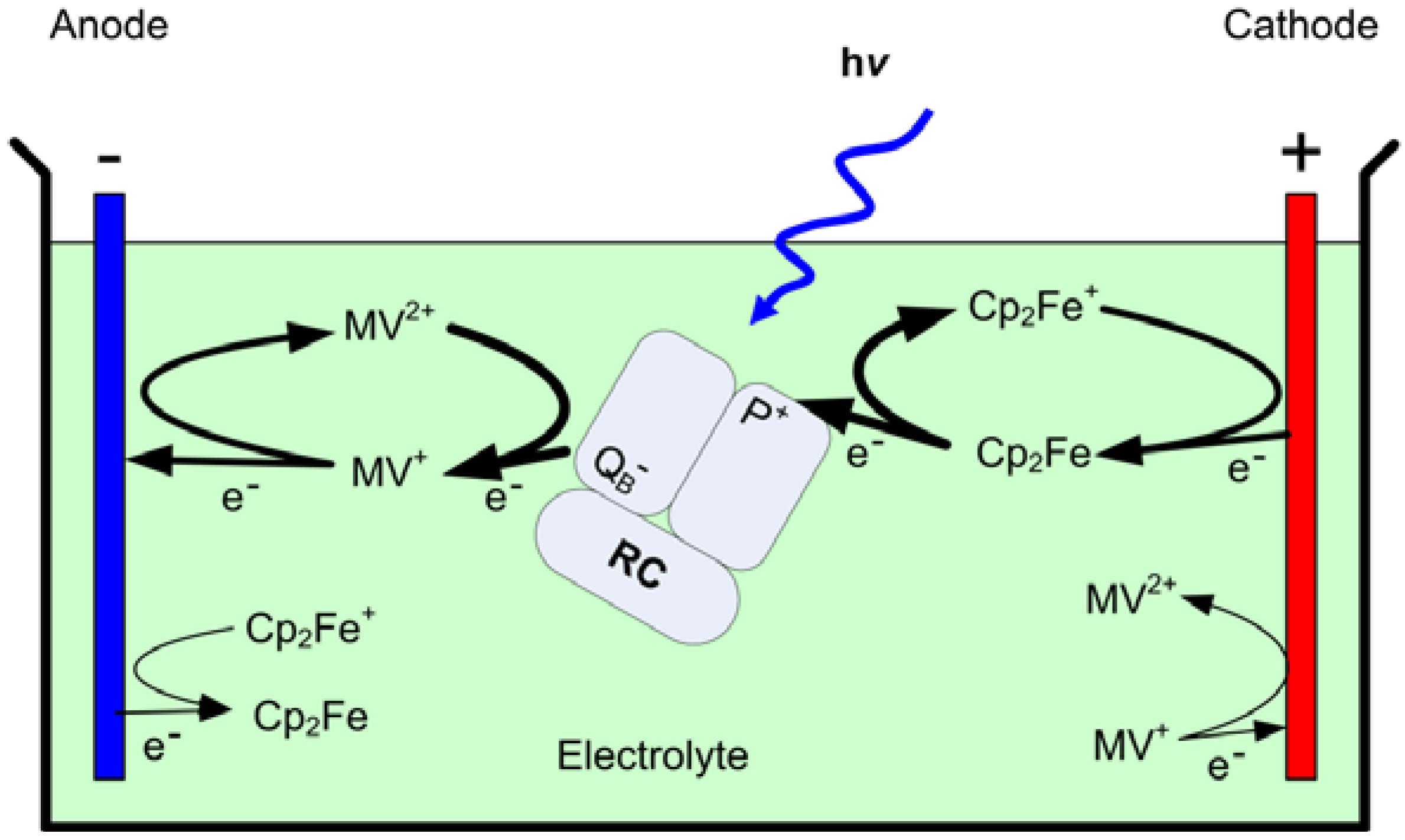
Using the foregoing information, a photovoltaic device can be fabricated using a solution containing the RC and mediators as the electrolyte, and two different electrodes to form an electrochemical cell (
Figure 2). If the reduction rate of Cp
2Fe
+ at the surface of one of the electrodes is faster than both the recombination rate in reaction (3) and the oxidation rate of MV
+, a photocathodic current is obtained from the electrode (cathode). At the anode, the oxidation rate of MV
+ must be faster than the recombination and Cp
2Fe
+ reduction rates to achieve a steady state photocurrent from the device terminals. Because the rates of reactions at the electrode surfaces are proportional to the concentration of the photoactivated mediators, the photocurrent is expected to increase with an increase in
G [
14].
Figure 2.
A schematic of the structure and operation of the bio-photovoltaic device. The thick arrows represent reactions with high reaction rate constants, while the thin arrows represent reactions that reduce cell efficiency.
Figure 2.
A schematic of the structure and operation of the bio-photovoltaic device. The thick arrows represent reactions with high reaction rate constants, while the thin arrows represent reactions that reduce cell efficiency.
Assuming that the charge transfer to the mediators is not the rate-limiting step,
G is proportional to the absorption of photons by RC. According to the Beer-Lambert law, the intensity of the light in a solution decreases exponentially with the concentration of the absorbing species. For a monochromic light with the incident intensity of
I0, the intensity of the absorbed light,
I, inside a transparent cell with the depth of
l is expressed by:
where
CRC is the concentration of the RC and
ε is the extinction coefficient of the RC for that wavelength. For a white light source, the integral of equation 4 across the spectrum determines the intensity of the absorbed light (
I). Since
G and photocurrent are proportional with the intensity of the absorbed light, both are expected to increase linearly with the total beam intensity
I0, and increase with an increase in
CRC.
3. Experimental Section
The new photovoltaic device was fabricated in a 4 mL glass fluorometer cuvette (1 cm × 1 cm path length). Cultures of
R. sphaeroides strain ΔPUHAΔPUC containing a plasmid expressing a His-tagged RC H protein were grown as previously described [
15], and the RC purified as described [
16]. The concentration of RC after purification was 18 µM, based on the absorption peak at 804 nm. An aqueous solution of 0.75 mM Cp
2Fe and 0.75 mM MV
2+ (both from Sigma) in Tris-HCl buffer (pH 8), 0.1%
N,N-dimethyl-dodecylamine
N-oxide (LDAO), and various concentrations of the RC were used as the electrolyte. The concentration of mediators is chosen to be much higher than the RC concentration so as not to limit the photocurrent with a shortage of mediators. The solubility of ferrocene is limited to 0.8 mM. Based on our previous experimental results we chose highly ordered pyrolytic graphite (HOPG) for the cathode and a platinum wire for the anode [
8]. The HOPG, purchased from SPI, was a freshly cleaved layer with an area of 1 cm
2. The area of the platinum wire was 0.5 cm
2. The photocurrent in the electrochemical cell was measured with a Solartron SI 1287 electrochemical interface. To eliminate the effect of ambient light the electrochemical cell was placed in a black box equipped with an electrical shutter. Using an Oriel solar simulator (AM 1.0) a beam of white light with an incident intensity of 2.8 mW/cm
2 illuminated a side of the cell through an optical fiber. During measurement, a voltage equal to the open circuit potential in the dark was applied across the cell and the current recorded upon illumination [
7].
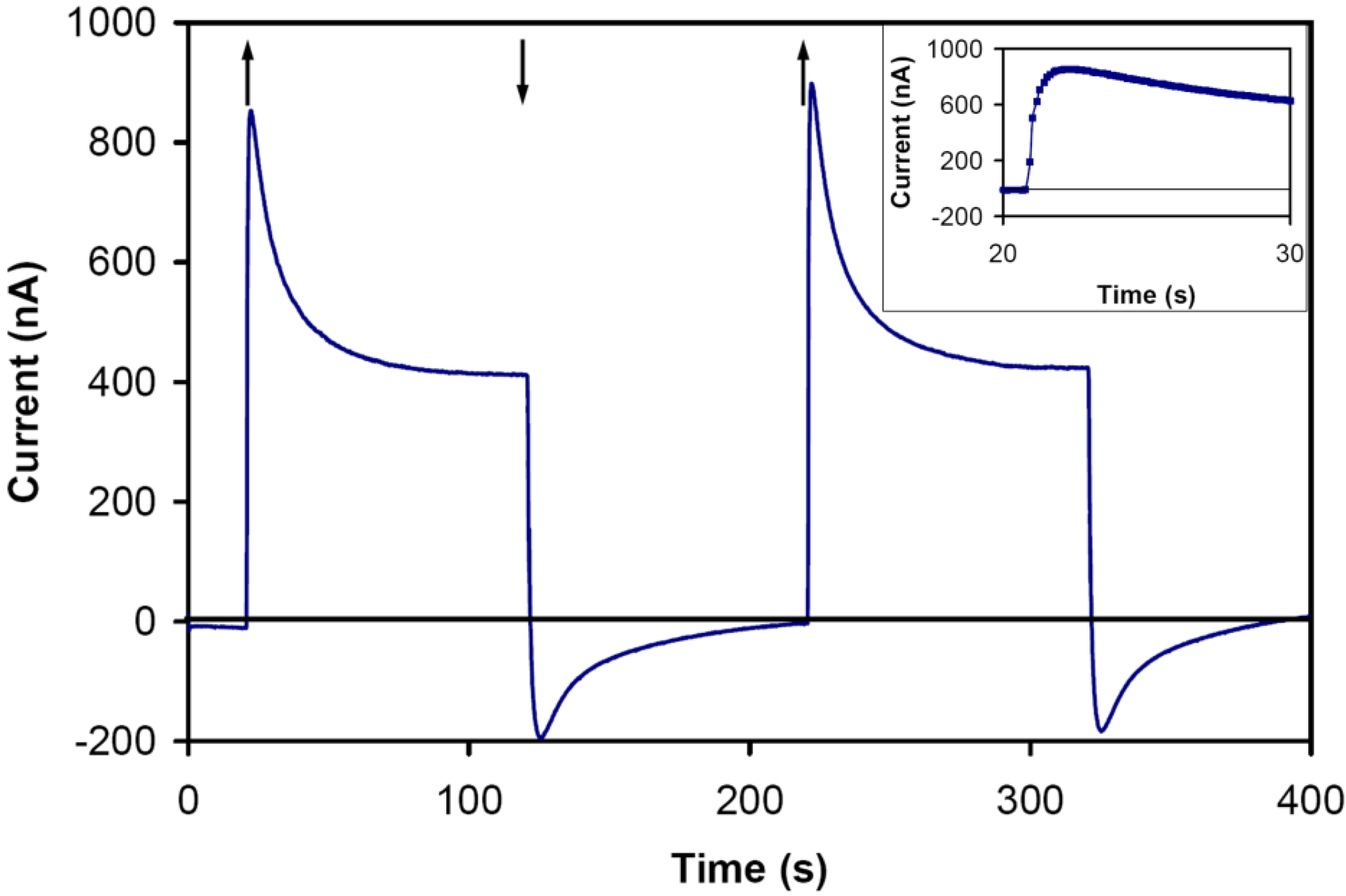
In the absence of the RC in the electrolyte, no photocurrent was detected when the cell was illuminated. A very small photocurrent (~2 nA) was measured in a cell with an electrolyte containing the RC but no mediators. Using an electrolyte with 15 μM of RC, 0.75 mM of Cp
2Fe and 0.75 mM of MV
2+, the current responded to the light (
Figure 3). The rapid increase in the current and the gradual drop in the transient response are likely due to different reaction rates of competing mediators at the surface of the electrodes. Assuming that reduction of Cp
2Fe
+ and oxidation of MV
+ take place with different rates at the electrode surfaces, the total current is expected to be a superposition of a cathodic and an anodic current, each having different time constants. The difference between rates also determines the steady state photocurrent. The measured current did not change when the electrode surface area was reduced by a factor of two, indicating that the surface area of the electrodes and kinetics of electron transfer at the electrode surfaces are not limiting the current. Also, no change in the performance was observed when the device was illuminated for a few hours. However, the performance was degraded in a few days even when the cell was not illuminated, which was likely due to the denaturalization of the proteins at room temperature.
Figure 3.
The photocurrent response for the cell with the electrolyte of 15 μM RC, 0.75 mM ferrocene, and 0.75 mM methy viologen. The intensity of the incident light was 2.8 mW/cm2. Light on, ↑; light off, ↓. (inset) The transient response with larger magnification. The response is likely a superposition of a fast and a slow anodic and cathodic currents.
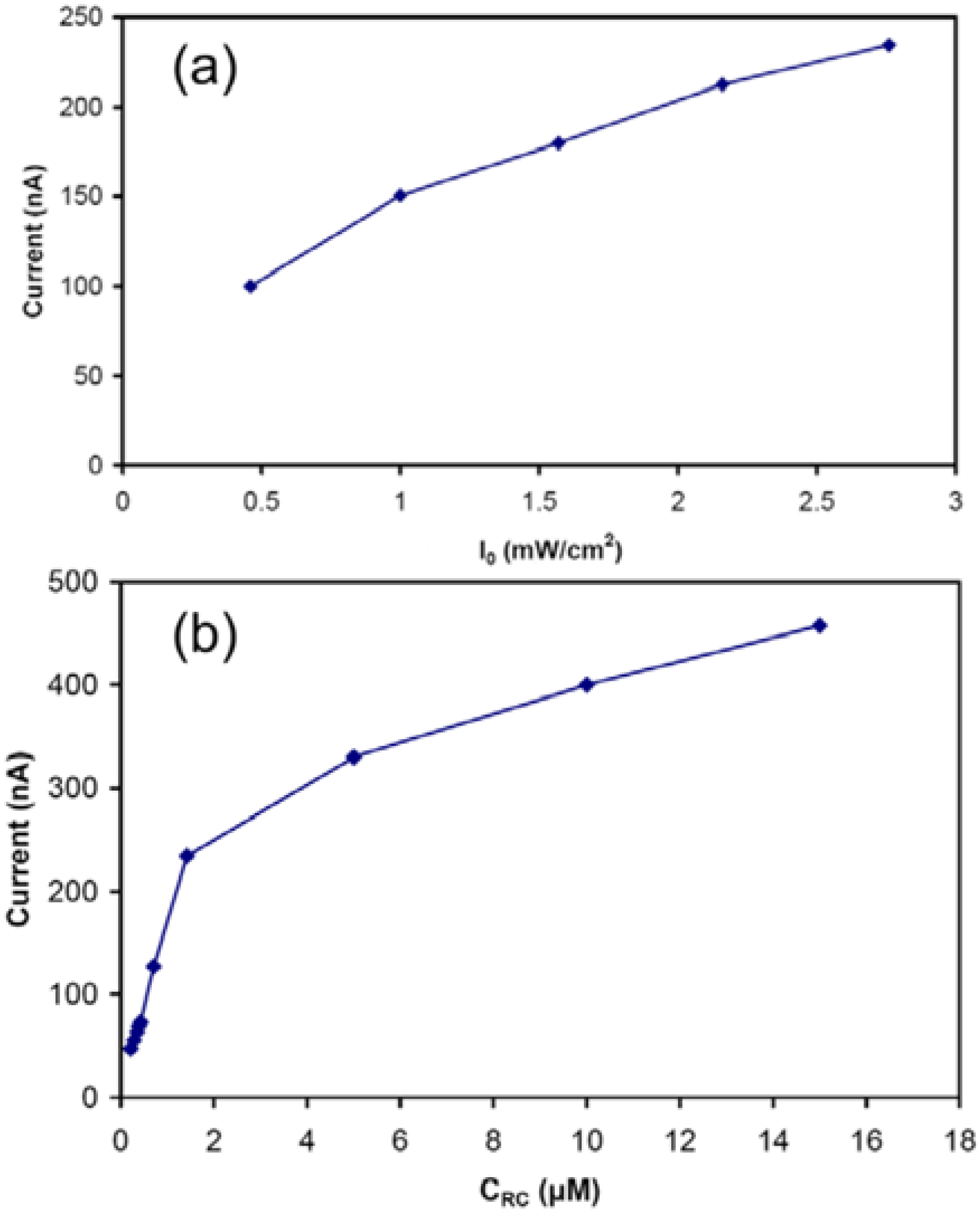
In order to study the effect of light intensity, the photocurrent was measured using several intensities. As shown in
Figure 4(a), the value of the steady state current changes almost linearly with the variations in the light intensity. The current was also recorded for different concentrations of RC ranging between 0.2 and 15 μM. As shown in
Figure 4(b), the photocurrent increased with the increase in the concentration of the RC with a trend predicted by equation (4). Although the increase in the photocurrent was not a linear function of the RC concentration, the photocurrent did not appear to reach a plateau at the highest RC concentration (15 µM) tested, suggesting that further improvement is possible if RC concentration can be increased beyond the maximum concentration we had available to us.
HOPG and Pt electrodes worked for a proof of concept prototype, but they are not ideal materials for the electrodes as they appear to allow both forward and reverse reactions, leading to cell inefficiencies. In order to have a selective reaction at each electrode, semiconducting electrodes with energy levels match with the reaction potentials can be deployed. Similarly, alternative mediators may function more efficiently. Further optimization of this approach promises to enable high absorption of light in the cell, and, with better electrode selectivity, a great improvement in device efficiency.
Figure 4.
(a) The magnitude of the steady state photocurrent versus the light intensity for the cell with the electrolyte containing 1.4 μM of RC. (b) The magnitude of the steady state photocurrent versus the concentration of RCs in the electrolyte. The intensity of the incident light was 2.8 mW/cm2.

