Article

Comparison of Hybrid Blends for Solar Cell Application

1
Max Planck Institute for Polymer Research, Ackermannweg 10, 55128 Mainz, Germany
2
Institute for Physical Chemistry, Johannes Gutenberg University, Jakob-Welder-Weg 10, 55099 Mainz, Germany
3
Institute for Inorganic Chemistry and Analytical Chemistry, Johannes Gutenberg University, Duisbergweg 10-14, 55099 Mainz, Germany
4
Institute for Organic Chemistry, Johannes Gutenberg University, Duisbergweg 10-14, 55099 Mainz, Germany
5
School of Chemical and Biological Engineering, WCU program of Chemical Convergence for Energy & Environment (C2E2), College of Engineering, Seoul National University, 151-744 Seoul, Korea
*
Author to whom correspondence should be addressed.
Energies 2010, 3(3), 301-312; https://doi.org/10.3390/en3030301
Submission received: 9 December 2009 / Revised: 22 January 2010 / Accepted: 29 January 2010 / Published: 5 March 2010
(This article belongs to the Special Issue Solar Cells)

Abstract

:
In blended hybrid systems distinct micro- or nanostructured materials can be formed by phase separation. Network structures of particles or rods in a polymer matrix can be developed via self-assembly. We use this blending approach to compare active materials for application in solar cell devices. Blends were fabricated from either poly(hexylthiophene) P3HT or poly(triphenylamine) PTPA mixed with nanocrystalline TiO2 rods. In this manner, we compare two different hole conducting polymers in their performance in photovoltaic devices, while experimental conditions are kept identical. We find that the choice of solvent and photovoltaic characterization conducted in inert atmosphere is of importance for blends prepared from P3HT/TiO2 blends, but not for PTPA/TiO2 blends. Even though prepared with the same TiO2 rods, solar cells prepared from PTPA blends showed an enhanced efficiency when measured under ambient conditions. Furthermore, the PTPA/TiO2 showed higher long-term stability.

1. Introduction

In the area of hybrid and organic solar cells, dye-sensitized solar cells (DSSC), like the ‘Grätzel-cell’, show the highest power conversion efficiency. In such ‘Grätzel-cells’, I/I3− dissolved in acetonitrile is commonly used as electrolyte. However, cells based on this volatile and corrosive electrolyte present problems in their sealing, which is a major drawback in terms of long term stability. As alternatives to the liquid electrolyte in DSSCs, various solid state and dye sensitized solid state hybrid solar cells have been investigated. A variety of inorganic/organic combinations have been found to be suitable as functional hybrid materials for solar cells. Semiconducting metalchalcogenides and oxides like CdSe, CdTe, PbS, PbSe, ZnO, TiO2 in combination with hole conducting organic materials like MEH-PPV (poly(2-methoxy-5(2′-ethyl)hexoxy-phenylenevinylene)), P3HT (poly(3-hexylthiophene)), Spiro-OMeTAD (2,20,7,70-Tetrakis-(N,N-di-4-methoxyphenylamino)-9,90-spiro-bifluorene), PTPA (poly(triphenylamine)) were found to be promising for photovoltaic applications [1]. There are several ways of designing an interface between the inorganic electron conducting and organic hole conducting part. In this study we focus on blended systems of different organic hole conductor and TiO2 rods. In such blended systems, phase separation leads to formation of interconnected pathways. Interconnected pathways are desirable because the charge has to travel from the interface towards the electrodes.
Blending the active components also offers additional advantages. Components can be optimized separately, which enables calcination of the inorganic semiconductor at elevated temperatures. This process yields inorganic particles with the desired crystallographic modification. Furthermore, the organic materials can be tuned to improve the miscibility of the organic and inorganic phase in a blend [2] or to selectively dissolve the inorganic part in one phase.
To date, hybrid solar cell blends of CdSe and CdTe [3] combined with poly (thiophenes) show highest efficiencies. However, we concentrate on TiO2 phases in combination with P3HT or PTPA. We believe that because of mild environmental impact and its low cost TiO2 seems to be more promising component than Cd-based blends. Additionally, TiO2/spiro-MeOTAD cells [4] show up to 4% efficiency, depending on the kind of hole conductor.
Comparison of solar cells assembled by different research groups is difficult: the overall power conversion efficiency is strongly influenced by the combination of hole and electron conductor and on the added dye, in case of dye sensitized cells. Also device properties like, e.g., layer thickness, measurement techniques (e.g., measuring at 1 sun) and device preparation conditions (annealing, use of barrier and protecting layers, etc.) have an impact on the solar cell efficiency. To alleviate this problem, two different hole-conducting polymers are used in this study in combination with TiO2. For a direct comparison of these materials, device preparation and measurement were identical.

2. Results and Discussion

Hybrid solar cells were prepared from blend systems using crystalline TiO2 nanorods with either one of the hole conducting polymers P3HT (poyl(hexylthiophene)) or PTPA (poly(triphenyl-amine)). The TiO2 rods were prepared from a TiCl4 precursor leading to a crystalline product with distinct diameter but polydisperse rod length, ranging from about 1 to 10 µm (Figure 1). The reason for the preferred rod formation over the formation of wires that normally occur under these reaction conditions is the presence of residual chloride ions that could not completely be removed by washing (see experimental). Chloride ions are believed to be a structure directing agent to favor growth of short rods over long wires [5].
Figure 1. TEM picture of TiO2 rods.
Energies 03 00301 g001
Alivisatos et al. showed the advantages of using rods instead of particles in a blend to create an interpenetrated network system that simplifies electron conduction through the active material. In small particle networks charges have to overcome more grain boundaries than in networks formed by rods [6].
The hole conducting part of the hybrid blends are P3HT (with a Mn of about 4,000 g/mol) and PTPA (with a Mn of about 26,000 g/mol and a PDI of 1.3) polymers. The blends were prepared by mixing the TiO2 rods with the polymer phase in either THF or chlorobenzene. The weight ratio of polymer and TiO2 used was chosen to be 1:1, since this ratio had been reported by Yu et al. to be most efficient in P3HT:TiO2 blends compared to several other ratios [7].
SEM pictures of drop casted films show that the TiO2 rods are nicely distributed throughout the films, for P3HT blends (Figure 2 a,c) as well as for PTPA blends (Figure 2 b,d). By burning away the polymer matrix (PTPA and P3HT) the TiO2 network is revealed showing that the rods are touching each other to create a percolating network (c,d).
Figure 2. SEM pictures of polymer-TiO2 blends. (a) TiO2 rods in a P3HT matrix. (b) TiO2 rods in a PTPA matrix. (c) Calcined sample of TiO2-rods from P3HT matrix. (d) Calcined sample of TiO2 from PTPA matrix.
Energies 03 00301 g002
The polymer/TiO2 blends were prepared under ambient condition and tested in solar cell devices as follows. An inverse assembly was used with FTO coated glass as transparent electrode and gold as counter electrode. The active TiO2-polymer layer was embedded in a TiO2 barrier layer on top of the FTO and a PEDOT:PSS protecting layer underneath the gold electrode (FTO/ncTiO2/blend/PEDOT:PSS/Au). The active layer thickness of the drop coated blend mixtures were around 2 µm as seen in Figure 3.
Figure 3. SEM pictures of cross section of P3HT/TiO2 hybrid solar cell.
Energies 03 00301 g003
Results of blends drop coated from THF solution and measured as solar cells at 1 sun (1,000 W/m2) with 1.5 AM filter are shown in Table 1.
Table 1. Measurements of solar cell devices under 1 sun and 1.5 AM. (FF: fill factor, VOC: open circuit voltage, ISC: short circuit current, Eff: power conversion efficiency).The blend materials were drop casted from THF solution. (PA): Measured in protecting atmosphere.
Device assembly*FF/%Voc/VIsc/A/cm2Eff/%
PTPA29–0.160.7 × 10−40.002
PTPA/PA28–0.110.6 × 10−40.001
PTPA/PEDOT30–0.231.0 × 10−40.007
PTPA/PEDOT/PA30–0.191.2 × 10−40.006
P3HT36–0.751.5 × 10−40.03
P3HT/PA41–0.772.0 × 10−40.11
P3HT/PEDOT28–0.372.5 × 10−40.03
P3HT/PEDOT/PA37–0.486.3 × 10−40.11
*All results are averages over 8 cells containing 6 pixels each (active area about 0.07 cm2).

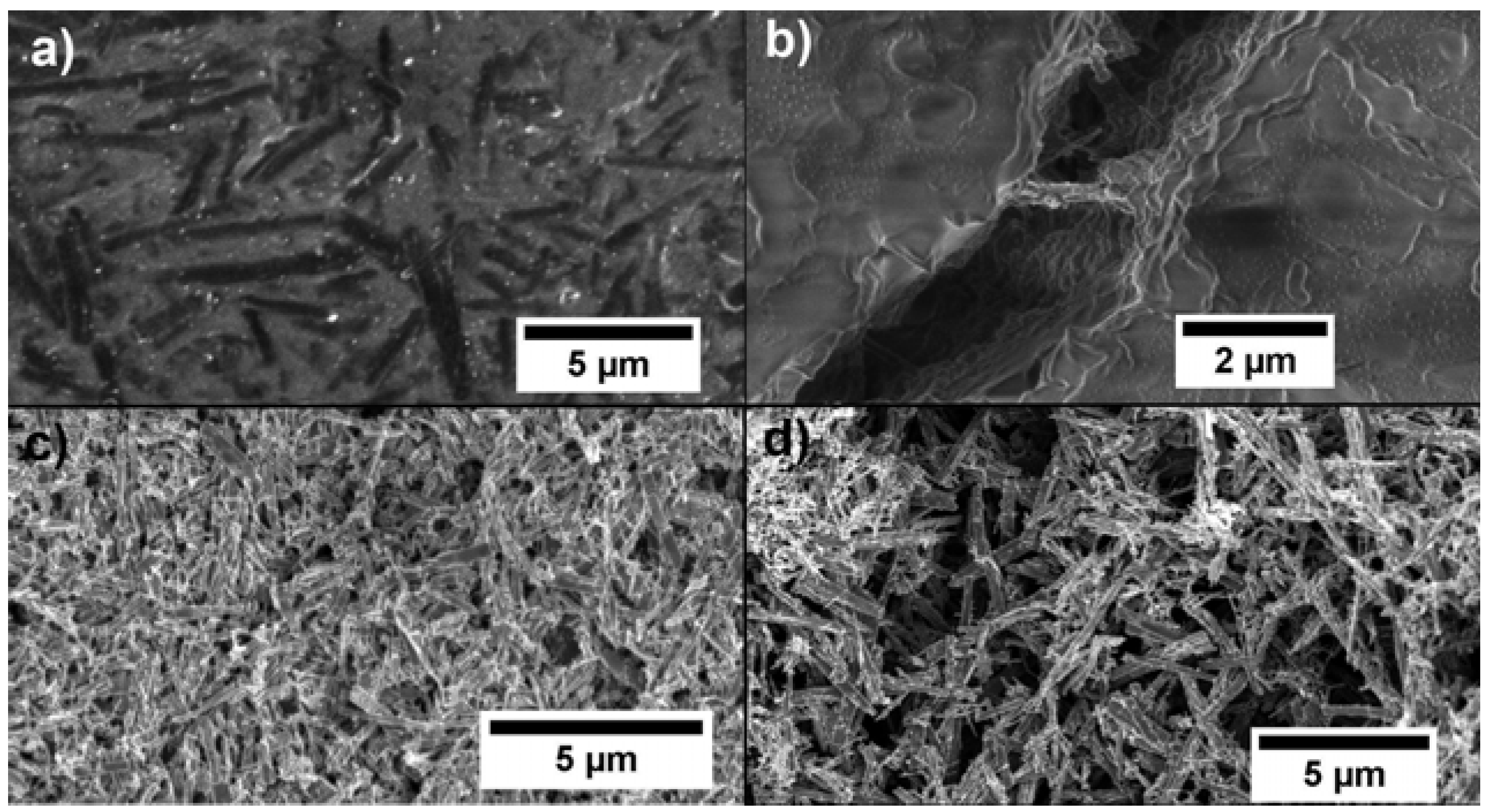
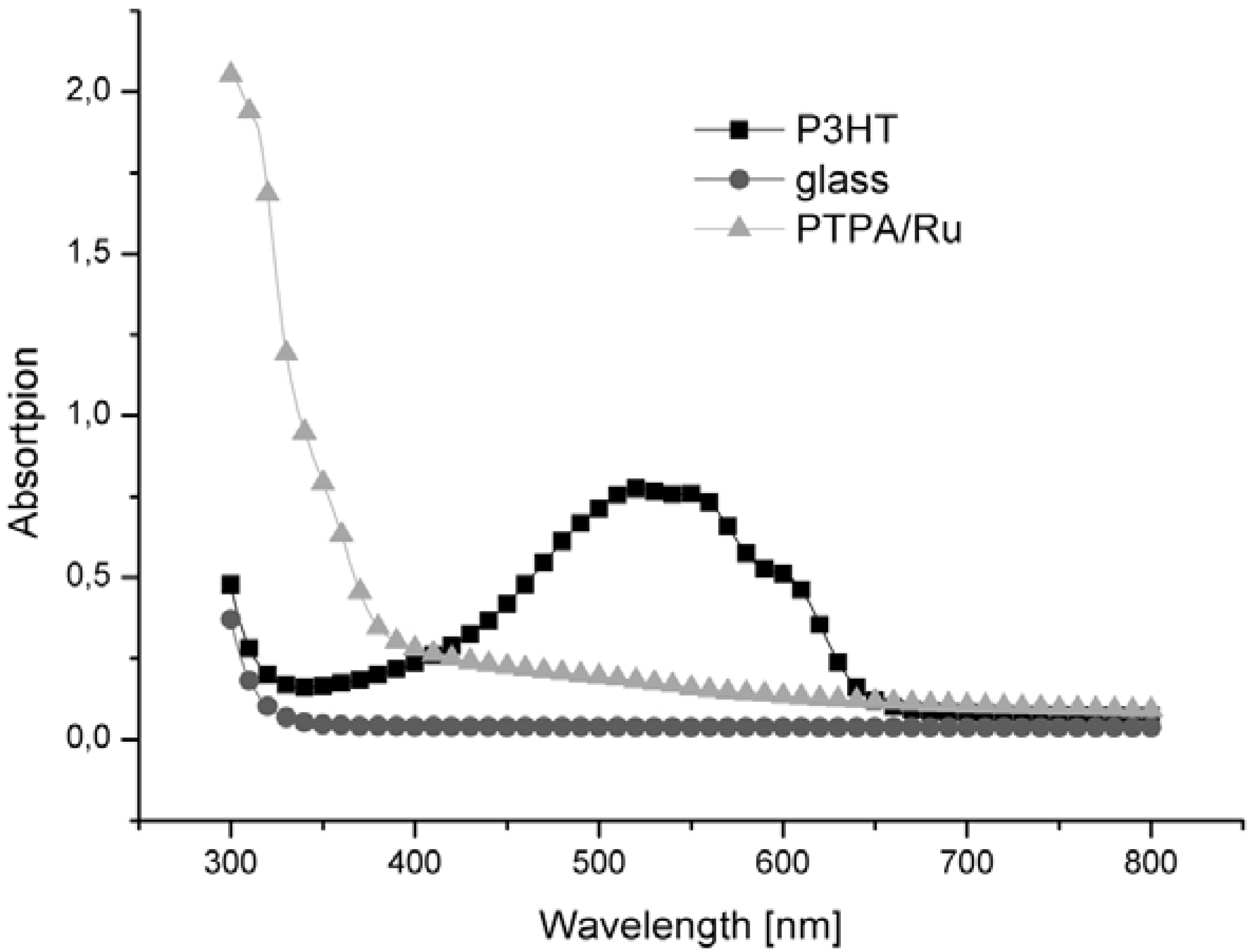
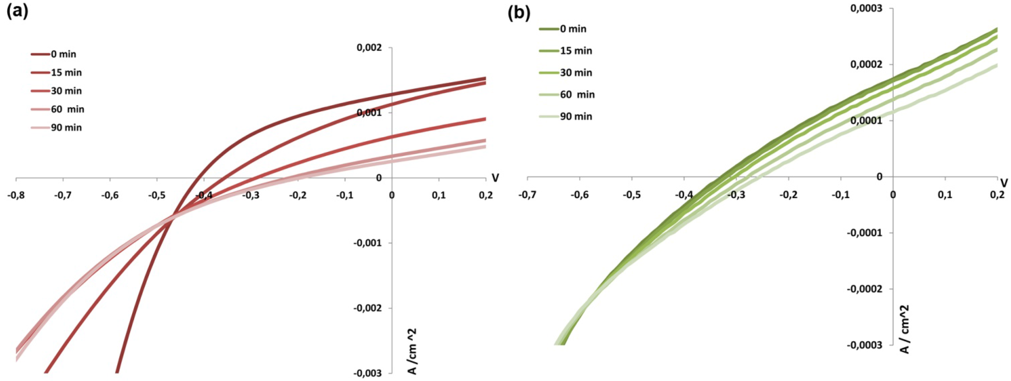
2.1. Comparison of PTPA and P3HT under Different Conditions

Comparing the results found in Table 1, P3HT is performing much better in solar cell devices than PTPA using identical TiO2 nano-rods. The reason for this is mainly due to the difference in optical properties of the films. For an efficient exciton creation, light has to be absorbed by the polymer or an additional dye. In the case of P3HT the absorption matches the sun’s spectrum (Figure 4), whereas PTPA does not absorb light in the visible range. Therefore a Ru-Dye (Cis-Ru(SCN)2(4,4´-dicarboxylic acid-2,2´-bipyridine)(4,4´-dinonyl-2,2´-bipyridine), Z907) is additionally introduced into the PTPA-TiO2-blend. However the standard Ru-dye does not absorb as much sunlight as the P3HT, as seen in the corresponding UV-VIS spectra. That might be one of the reasons why the PTPA-Ru-dye system works less efficient in a solar cell. Another reason might be the undefined localization of the dye molecules in the blend. As discussed in literature [8], the absorbing species should be adsorbed at the surface of the semiconducting metal oxide to inject electrons efficiently. To recover the dye the polymer phase has to transfer electrons towards it and therefore it is most convenient to sandwich the dye in between the hole and electron conducting part, i.e., the polymer and TiO2 phase respectively. In the blend of TiO2, Ru-Dye and PTPA the Ru-Dye is dissolved in the polymer/DMF mixture and upon addition of TiO2 rods it is expected that some dye attaches to the surface of the rods due to the -COOH groups of the Ru-ligands [9]. But it is also possible that some dye is distributed throughout the hole conducting material due to its solubility in the polymer/DMF solution and therefore opens ways of recombination and loss mechanisms. The importance of the interface modification is already reported in literature. Goh et al. studied the positive influences of the interface modification of hybrid TiO2/P3HT devices with interfacial dipoles and additional Ru-dyes adsorbed at the interface between TiO2 and P3HT [10]. They improved the power conversion efficiency from 0.35 to 0.6% with additional Ru-dye adsorbed at the TiO2 interface measured at 1.5 AM but without reported illumination intensity. Lin et al. reported the suppression of recombination at P3HT/TiO2 nanorod interfaces by the attachment of Cu and Ru-dye species and an additional capping of the rods with anthracene-carboxylic-acid [11]. They even reached promising efficiencies of up to 2.2% at 1.5 AM and 100mW/cm2 illumination.
Figure 4. UV-VIS diagram of blend films spin coated on glass slide.
Energies 03 00301 g004
Comparing the charge carrier mobility of PTPA (about 1 × 10⁻⁶ cm2/(Vs))and P3HT (about 4 × 10⁻⁵ cm2/(Vs) for Mn ≈ 6000 g/mol) reported in literature [12,13], it is obvious why they perform differently when introduced in solar cell devices. The short circuit current (ISC) of P3HT blends is higher than for PTPA blends. An even bigger difference is found for the open circuit voltage (VOC) that is much higher for P3HT blends.
However the additional PEDOT layer seems to be sufficient for PTPA blends but not for devices prepared of P3HT blends. This is remarkable because as it is seen in the SEM image in Figure 2a, the TiO2 rods are clearly visible at the surface of the P3HT/TiO2 blend film. Therefore, a short circuit caused by a contact of the rods and the gold electrodes should be prevented by the PEDOT:PSS layer. An explanation might be a mismatch of the energy levels between the P3HT and PEDOT:PSS. In literature the donor material P3HT as well as PEDOT:PSS are cited with an HOMO of 5.2 eV [14,15].
In air solar cell measurements of P3HT and PTPA lead to divergent effects concerning the efficiency as seen in Table 1. As the used TiO2 is identical, the influence of oxygen can not to be attributed to the semiconducting metal oxide as it is reported in literature [16] but has to be a result of the different hole conducting polymer. In the systems studied here P3HT blends show much better performance in inert atmosphere as it is also known for fullerene/P3HT blends. P3HT is well known for the decrease in charge carrier mobility when measured [17] and prepared under ambient condition [18]. Although we build all devices under ambient conditions, the ones measured under protective atmosphere were stored under argon for at least 12 h prior to measurement. Since this treatment was found to be beneficial towards an increase in power conversion efficiency, it is an indication for reversible oxygen doping of the P3HT/TiO2 matrix. However, in order to recover their initial photovoltaic performance Wang et al. found oxygen to be indispensable for P3HT/TiO2 hybrid solar cells during long-term measurements [19]. Since P3HT/TiO2 blends reported here are much more efficient when measured under inert gas we could not reproduce this behavior. In Figure 5 the I-V-curves of devices measured at constant illumination (1 sun and 1.5 AM) are shown for the P3HT (a) and PTPA (b) blends. For both blends a decrease in ISC and VOC can be detected. However for the P3HT blend, the curve changed upon illumination (Figure 5a) while measured in inert atmosphere. The same decrease in efficiency was found for long-term measurements done in air. Lira-Cantu et al. proposed the influence of the UV light to be the reason for the unsatisfying long-term stability [16]. This can be excluded as an explanation in our experiment, since the light has to pass through FTO coated glass and thus only little UV light should reach the active layer. Since P3HT blends show a decay of efficiency by an order of magnitude (Table 2), although measured in inert atmosphere, the influence of oxygen does not give an explanation as well. Furthermore in the case of PTPA blends oxygen seems to be necessary.
On the contrary the TiO2/PTPA blends show an increased efficiency when measured under ambient conditions (Table 1). Furthermore the decay of the power conversion efficiency was less dramatic upon continuous white light illumination (Table 2 and Figure 5b). Hence for the PTPA/TiO2 system the above described positive influence of oxygen on hybrid systems is seen. Kempa et al. already demonstrated the long-term and air stability of PTPA in field effect transistors [20]. This is in good agreement with our observations.
Figure 5. Long-term exposure of devices at 1 sun and 1.5 AM. (a) TiO2/P3HT blend, measured in inert atmosphere (with PEDOT layer; active area: 0.063 cm2), (b) PTPA/TiO2 blend, measured under ambient condition (with PEDOT layer; active area: 0.072 cm2).
Energies 03 00301 g005
Table 2. Efficiency progression during long-term illumination. (PA): Measured in protecting atmosphere.
Device assembly0 min15 min30 min60 min90 min
Eff. (%)*P3HT/PA0.1020.0560.0270.0110.007
Eff. (%)*PTPA0.010.010.0090.0070.006
* Efficiencies are averages taken from 6 pixels of one device.

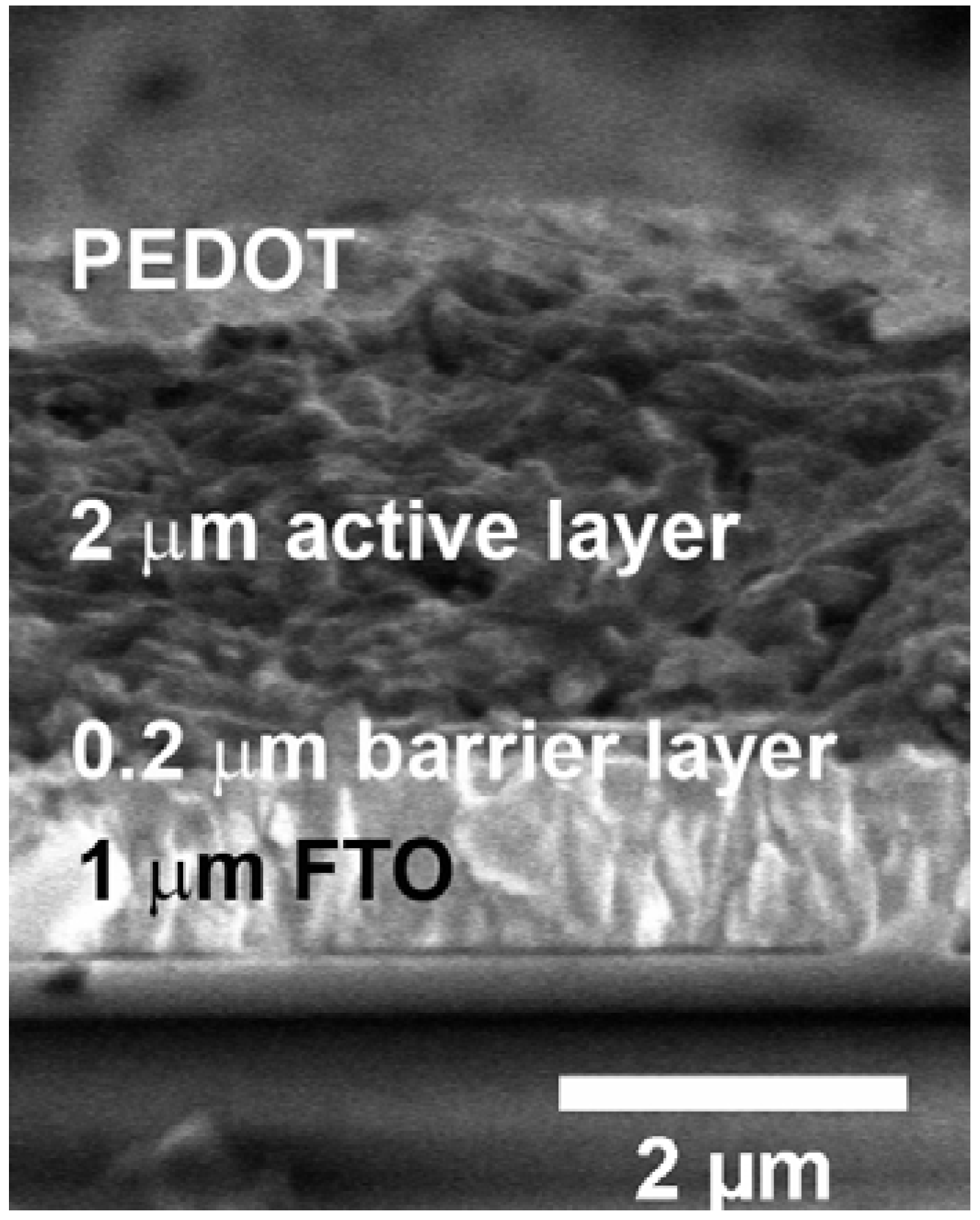
2.2. Further Improvement of P3HT/TiO2 Blend Devices

It is well known that by using chlorobenzene as solvent instead of THF the overall power conversion efficiency for P3HT systems e.g. in combination with fullerene materials can be doubled. Also in hybrid heterojunction bulk systems the overall efficiency can be largely influenced by the choice of solvent. In this case xylene was found to be most effective [21]. In our hybrid systems, we could double the power conversion efficiency from 0.11% to 0.22% by changing the solvent from THF to chlorobenzene (see Table 3 compared to Table 1). The choice of solvent has a strong influence on the structure of the polymer film formed by evaporation of the solvent. Kwang et al. also showed the strong influence of the solvent on the device performance when prepared from TiO2 in a P3HT matrix. They obtained 0.18% for cells casted from chlorbenzene solutions and 0.033% for cells casted from THF solution [21].
Table 3. Measurements of solar cell devices under 1 sun and 1.5 AM. The blend materials were drop casted from chlorobenzene solution. PA: measured in protecting atmosphere. Annealed: Annealing was done at 160 °C for 10 min.
Device assembly* FF /% Voc/ V Isc/ A/cm2Eff /%
P3HT/PA 31 –0.33 1.5 × 10−30.22
P3HT/Annealed/PA 29 –0.29 4.8 × 10−40.04
P3HT/Annealed 30 –0.36 4.5 × 10−40.05
P3HT 31 –0.35 1.3 × 10−30.13
*All results are averages taken from 8 cells containing 6 pixels each.
In fullerene-P3HT systems, annealing and choice of solvent have a major influence on the film morphology. Drying slowly leads to phase separation and affects crystallization [22]. Casting films from solvents with a lower vapor pressure like xylene and chlorobenzene is more appropriate than solvents like THF and chloroform. As seen in Table 3 and Table 1 the ISC for blends drop coated from chlorobenzene increased one order of magnitude compared to devices prepared from THF solution (from 2 × 10⁻⁴ to about 2 × 10⁻³). The degree of crystallinity of P3HT is of importance for its hole conducting ability. Therefore, additional time for P3HT crystallization given during evaporation of the solvent is beneficial. Here the potential advantage of using PTPA in optoelectronic devices becomes evident. Since PTPA is an amorphous hole conductor [20] the use of a high boiling solvent or an extra annealing step is redundant. Surprisingly further thermal annealing of the investigated P3HT films does not improve solar cell performance either. The commonly applied thermal treatment for P3HT films at 160 °C for 10 min leads to a drop of the power conversion efficiency. This is likely due to the small molecular weight of the used P3HT. Other than that, the annealing possibly leads to a higher concentration of oxygen in the film because the heat treatment was performed under ambient condition. Furthermore the TiO2 rod network might not be flexible enough to survive morphology changes in the µm range during phase separation.
Higher efficiencies for TiO2/P3HT blend solar cell devices are reported by Wu et al.. Efficiencies of 0.65% were reached by adding PMMA into the TiO2 nanorod/P3HT blend [23]. It was claimed that the additional PMMA smoothes the film and reduces the occurrence of pores and defects. Another approach for these kinds of hybrid composites was published by Williams et al., where nanostructured TiO2-P3HT composites were formed via an imprinting technique. Without an additional dye efficiencies of about 0.33% were obtained, while after addition of a Ru-dye over 0.6% power conversion efficiency were reached [24]. An explanation for the higher efficiencies compared to this study might be the different P3HT polymer used. Indeed, the P3HT used here has a molecular weight of only 4,000 g/mol. P3HTs with small molecular weight are known to have lower hole mobility than high molecular weight polymers and therefore lower power conversion efficiencies. Wu et al. found a power conversion efficiency of 0.2% for low molecular weight (about 10,000 g/mol) that perfectly matches with the result of 0.22% obtained in this study with a P3HT of even smaller molecular weight (4,000 g/mol) [25]. With an increased molecular weight of 66,000 g/mol Wu et al. almost reached 1% efficiency.

3. Experimental Section

Synthesis of crystalline TiO2 rods [26]: 0.55 ml of TiCl4 (stored under argon) were taken out in an argon counter stream and then dissolved in 100 ml of ethanol. Within 15 minutes, 40 ml of 1 M NaOH solution were added under stirring. Stirring was continued for another 30 minutes. The suspension was filtered and the precipitate was washed with water until no chloride ions were found in the filtrate anymore, which was tested by addition of 0.1 M AgNO3 solution to the filtrate. A white precipitate was obtained. 50 ml of 10 M NaOH solution and the precipitate were mixed and stirred for 30 minutes. 25 ml of the suspension were transferred into a 50 ml Teflon vessel. Afterwards The sealed autoclave was treated at 200 °C (the furnace was preheated to this temperature) for 24 h. Samples were naturally cooled down to room temperature. The residual NaOH-solution was removed by centrifugation, followed by washing the sample with 0.1 M HNO3 until acidic reaction. The sample was subsequently washed with 0.1 M HCl once and with water until neutral reaction of the supernatant solution was reached. The sample was dried over night in a desiccator over silica gel and in vacuum. Afterwards the sample was calcined at 600 °C for 4 h. The heating and cooling rate was 1 °C/min.
P3HT-Blend Systems: Blend materials were prepared by mixing TiO2 rods (0.01 g) and P3HT (0.01 g) dissolved in THF or chlorobenzene (1 mL) upon 5 min of ultrasound irradiation.
PTPA-Blend Systems: Blend materials were prepared by mixing TiO2 rods (0.01 g), Ru-dye Z907 (0.005 g) and PTPA (0.01 g) (1:1 wt% ratio) dissolved in THF (1 mL) upon 5 min of ultrasound irradiation.
Solar Cell Device Preparation: Films were drop casted on a TiO2 barrier layer and dried over night under ambient condition. The barrier layer was prepared according to literature [27] and spin coated (1,000 rpm, 60 s) on commercially available FTO glasses. On top of the active material a PEDOT:PSS layer was spin coated (2,000 rpm, 60 s) (if indicated) and finally gold electrodes with 100 nm thickness were evaporated. Measurements were taken under ambient condition as well as in protecting atmosphere (after storage of the devices in a glove box for least 12 h).
PTPA and P3HT were synthesized according to literature [28, 29].
Cis-Ru(SCN)2(4,4´-dicarboxylic acid-2,2´-bipyridine)(4,4´-dinonyl-2,2´-bipyridine) (Z907) was synthesized according to literature [30].

4. Conclusions

Comparing PTPA and P3HT blends, the advantage of the latter clearly lies in the higher overall power conversion efficiency. Focusing on the long term stability, PTPA shows better performance. Furthermore, the PTPA blends are air stable and do not require special solvents or annealing treatment since they are amorphous polymers. This leads to convenient preparation methods. As long as the low charge carrier mobility is not increased and the need for an efficient and expensive dye is not solved the P3HT seems to be the hole conducting polymer of choice. Even though the preparation is more challenging due to solvent and heat annealing steps, air and long-term instability, P3HT systems are well studied and offer promising results in optoelectronic application.

Acknowledgements

Financial supports from the Max Planck Society and the Korean German IRTG Program (DFG Graduiertenkolleg 1404) is appreciated. We thank Gunnar Kircher for the synthesis of low molecular weight P3HT and the Ru-dye Z097 and we thank Mordechai Sokuler.

References and Notes

  1. Kumar, S.; Scholes, G.D. Colloidal nanocrystal solar cells. Michrochim. Acta 2008, 160, 315. [Google Scholar] [CrossRef]
  2. Chang, Y.M.; Su, W.F.; Wang, L. Photoactive polythiophene: Titania hybrids with excellent miscibility for use in polymer photovoltaic cells. Macromol. Rapid Commun. 2008, 29, 1303–1308. [Google Scholar] [CrossRef]
  3. Yoonmook, K.; Nam-Gyu, P.; Donghwan, K. Hybrid solar cells with vertically aligned CdTe nanorods and a conjugated polymer. Appl. Phys. Lett. 2005, 86, 113101. [Google Scholar] [CrossRef]
  4. Schmidt-Mende, L.; Bach, U.; Humphry-Baker, R.; Horiuchi, T.; Miura, H.; Ito, S.; Uchida, S.; Grätzel, M. Organic dye for highly efficient solid-state dye-sensitized solar cells. Advan. Mater. 2005, 17, 813–815. [Google Scholar] [CrossRef]
  5. Huang, Q.; Gao, L. A simple route for the synthesis of rutile TiO2 nanorods. Chem. Lett. 2003, 32, 638–639. [Google Scholar] [CrossRef]
  6. Huynh, W.U.; Dittmer, J.J.; Alivisatos, A.P. Hybrid nanorod-polymer solar cells. Science 2002, 295, 2425–2427. [Google Scholar] [CrossRef] [PubMed]
  7. Yu, H.Z.; Liu, J.C.; Peng, J.B. Photovoltaic cells with TiO2 Nanocrystals and conjugated polymer composites. Chin. Phys. Lett. 2008, 25, 3013–3016. [Google Scholar] [CrossRef]
  8. Kroeze, J.E.; Hirata, N.; Schmidt-Mende, L.; Orizu, C.; Ogier, S.D.; Carr, K.; Grätzel, M.; Durrant, J.R. Parameters influencing charge separation in solid-state dye-sensitized solar cells using novel hole conductors. Adv. Funct. Mater. 2006, 16, 1832–1838. [Google Scholar] [CrossRef]
  9. Zakeeruddin, S.M.; Nazeeruddin, M.K.; Humphry-Baker, R.; Pechy, P.; Quagliotto, P.; Barolo, C.; Viscardi, G.; Gratzel, M. Design, synthesis, and application of amphiphilic ruthenium polypyridyl photosensitizers in solar cells based on nanocrystalline TiO2 films. Langmuir 2002, 18, 952–954. [Google Scholar] [CrossRef]
  10. Goh, C.; Scully, S.R.; McGehee, M.D. Effects of molecular interface modification in hybrid organic-inorganic photovoltaic cells. J. Appl. Phys. 2007, 101, 114503. [Google Scholar] [CrossRef]
  11. Lin, Y.Y.; Chu, T.H.; Li, S.S.; Chuang, C.H.; Chang, C.H.; Su, W.F.; Chang, C.P.; Chu, M.W.; Chen, C.W. Interfacial nanostructuring on the performance of polymer/TiO2 nanorod bulk heterojunction solar cells. J. Amer. Chem. Soc. 2009, 131, 3644–3649. [Google Scholar] [CrossRef]
  12. Kessler, D.; Lechmann, M.C.; Noh, S.; Berger, R.; Lee, C.; Gutmann, J.S.; Theato, P. Surface coatings based on polysilsesquioxanes: Solution-processible smooth hole-injection layers for optoelectronic applications. Macromol. Rapid Commun. 2009, 30, 1238–1242. [Google Scholar] [CrossRef] [PubMed]
  13. Allard, S.; Forster, M.; Souharce, B.; Thiem, H.; Scherf, U. Organic Semiconductors for Solution-Processable Field-Effect Transistors (OFETs). Angew. Chem. Int. Ed. 2008, 47, 4070–4098. [Google Scholar] [CrossRef]
  14. Lechmann, M.C.; Kessler, D.; Gutmann, J.S. Functional templates for hybrid materials with orthogonal functionality. Langmuir 2009, 25, 10202–10208. [Google Scholar] [CrossRef] [PubMed]
  15. Shrotriya, V.; Li, G.; Yao, Y.; Chu, C.W.; Yang, Y. Transition metal oxides as the buffer layer for polymer photovoltaic cells. Appl. Phys. Lett. 2006, 88, 073508. [Google Scholar] [CrossRef]
  16. Lira-Cantu, M.; Norrman, K.; Andreasen, J.W.; Krebs, F.C. Oxygen release and exchange in niobium oxide MEHPPV hybrid solar cells. Chem. Mater. 2006, 18, 5684–5690. [Google Scholar] [CrossRef]
  17. Zhenan, B.; Ananth, D.; Andrew, J.L. Soluble and processable regioregular poly(3-hexylthiophene) for thin film field-effect transistor applications with high mobility. Appl. Phys. Lett. 1996, 69, 4108–4110. [Google Scholar] [CrossRef]
  18. Sirringhaus, H.; Tessler, N.; Friend, R.H. Integrated optoelectronic devices based on conjugated polymers. Science 1998, 280, 1741–1744. [Google Scholar] [CrossRef] [PubMed]
  19. Wang, M.; Wang, X. P3HT/TiO2 bulk-heterojunction solar cell sensitized by a perylene derivative. Solar Energ. Mater. Solar Cells 2007, 91, 1782–1787. [Google Scholar] [CrossRef]
  20. Kempa, H.; Reuter, K.; Bartzsch, M.; Hahn, U.; Huebler, A.C.; Zielke, D.; Forster, M.; Scherf, U. Proceedings of the 5th International Conference on Stability study of all-polymer field-effect transistors, Polymers and Adhesives in Microelectronics and Photonics, Wroclaw, Poland, October 2005; pp. 67–71.
  21. Kwong, C.Y.; Choy, W.C.H.; Djurisic, A.B.; Chui, P.C.; Cheng, K.W.; Chan, W.K. Poly(3-hexylthiophene):TiO2 nanocomposites for solar cell applications. Nanotechnology 2004, 15, 1156. [Google Scholar] [CrossRef]
  22. Chen, L.M.; Hong, Z.; Li, G.; Yang, Y. Recent progress in polymer solar cells: manipulation of polymer: Fullerene morphology and the formation of efficient inverted polymer solar cells. Adv. Mater. 2009, 21, 1434–1449. [Google Scholar] [CrossRef]
  23. Wu, M.C.; Liao, H.C.; Lo, H.H.; Chen, S.; Lin, Y.Y.; Yen, W.C.; Zeng, T.W.; Chen, C.W.; Chen, Y.F.; Su, W.F. Nanostructured polymer blends (P3HT/PMMA): Inorganic titania hybrid photovoltaic devices. Solar Energ. Mater. Solar Cells 2009, 93, 961–965. [Google Scholar] [CrossRef]
  24. Williams, S.S.; Hampton, M.J.; Gowrishankar, V.; Ding, I.K.; Templeton, J.L.; Samulski, E.T.; DeSimone, J.M.; McGehee, M.D. Nanostructured titania: Polymer photovoltaic devices made using PFPE-based nanomolding techniques. Chem. Mater. 2008, 20, 5229–5234. [Google Scholar] [CrossRef]
  25. Wu, M.C.; Chang, C.H.; Lo, H.H.; Lin, Y.S.; Lin, Y.Y.; Wen, W.C.; Yen, W.C.; Su, W.C.; Chen, Y.F.; Chen, C.W. Nanoscale morphology and performance of molecular-weight-dependent poly(3-hexylthiophene)/TiO2 nanorod hybrid solar cells. J. Mater. Chem. 2008, 18, 4097. [Google Scholar] [CrossRef]
  26. Oberle, P. New Nanomaterials for Dye Sensitized Solar Cells. Master Thesis, Johannnes Gutenberg University, Mainz, Germany, 2006. [Google Scholar]
  27. Yu, H.; Zhang, S.; Zhao, H.; Will, G.; Liu, P. An efficient and low-cost TiO2 compact layer for performance improvement of dye-sensitized solar cells. Electrochim. Acta 2009, 54, 1319–1324. [Google Scholar] [CrossRef]
  28. Behl, M.; Hattemer, E.; Brehmer, M.; Zentel, R. Tailored semiconducting polymers: Living radical polymerization and NLO-functionalization of triphenylamines. Macrom. Chem. Phys. 2002, 203, 503–510. [Google Scholar] [CrossRef]
  29. Jeffries-El, M.; Sauve, G.; McCullough, R.D. In-situ end-group functionalization of regioregular poly(3-alkylthiophene) using the grignard metathesis polymerization method. Adv. Mater. 2004, 16, 1017–1019. [Google Scholar] [CrossRef]
  30. Wang, P.; Zakeeruddin, S.M.; Moser, J.E.; Nazeeruddin, M.K.; Sekiguchi, T.; Gratzel, M. A stable quasi-solid-state dye-sensitized solar cell with an amphiphilic ruthenium sensitizer and polymer gel electrolyte. Nat. Mater. 2003, 2, 402–407. [Google Scholar] [CrossRef] [PubMed]

