1. Introduction
Over the last twenty years, wind energy has become the fastest developing renewable energy technology [
1]. The size of wind turbines has increased from a few tens of kWs in the 1980’s to multi-MW size today [
1]. With the development of wind turbine and power electronics technologies, large scale wind farms of hundreds of MWs of power are being developed in many countries around the world. More and more of these farms are proposed to be located offshore, due to large space requirements [
2]. Compared with the onshore wind farms, the offshore wind farms have access to significantly better wind energy resources and hence offer larger energy generating capability.
Meanwhile as the power capacity of the offshore wind farms increases, the adequacy of the wind farm electrical system design becomes critical. The overall purpose of designing the electrical system is to collect the energy from individual wind turbines, transmit it to the shore and convert it to appropriate voltage level to enable electricity grid interconnection. Electrical systems layouts aim to maximize the overall energy generation.
The ever increasing penetration level of wind power with the electricity grid also presents many challenges to modern power systems. In the past, it was common practice to disconnect a wind farm from the grid in the event of a network fault. However, as the generation capacity of wind farms has increased significantly and will continue to do so, the regulation of the technical management of the grid is necessary. New power electronic technologies must meet the technical requirements so that the large amounts of electricity generated by the wind can be injected into the grid at varying power level and from a range of wind farm locations [
1].
A large number of wind farms necessitate the development of DC transmission and distribution technologies. DC technologies offer a number of advantages such as low power losses, no connection distance limitation, no resonance etc. They also have major disadvantages concerning control and switching actions. High voltage alternating current (HVAC) subsea transmission schemes maybe used for offshore wind farms. However due to the limitation of the transmission distances, high voltage direct current (HVDC) transmission schemes are preferred. As a consequence, subsea power cables and DC circuit breakers (CBs) are a critical component of an HVDC transmission system used in any offshore electrical power scheme [
3,
4]. Considering the interconnection of offshore wind farms, technologies of DC transmission cables and CBs need to be understood.
This paper is organized as follows.
Section 2 provides a discussion of existing offshore wind farm power generation schemes.
Section 3 describes different electrical system configurations for offshore wind farms.
Section 4 summarizes the existing interconnection requirements which mainly include active power, frequency, reactive power voltage quality and fault ride-through requirement. The Section also discusses in detail the operation and control methods of large wind farms in case of electricity grid disturbances and faults. The technical issues associated with DC cables and DC (CBs) are discussed in
Section 5. Finally, conclusions are summarized in
Section 6.
2. Offshore Wind Farm Electricity Grid Interconnection
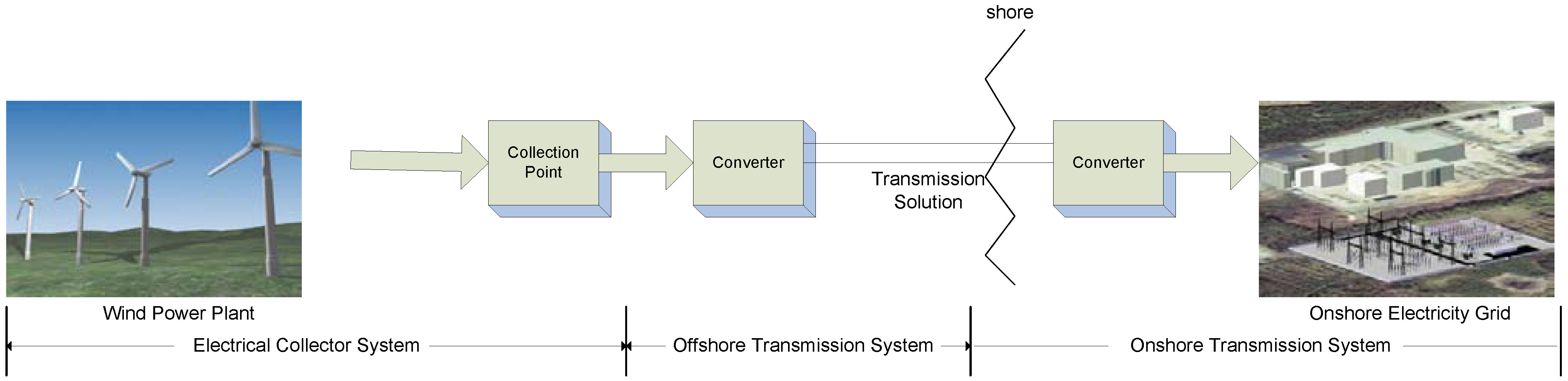
The main stages of large scale grid integrated wind energy systems are illustrated in
Figure 1. These stages include wind turbines, power electronic converters, transmission cables and CBs. The electrical collector system interconnects the wind turbines in the farm and connects them to the single collection point. For a small wind plant, the collection point lies in the basement of the tower. For a large wind plant, the collecting point can be part of an offshore substation or multiple collecting points might be used [
5].
Figure 1.
Schematic representation of a large scale offshore wind energy generation plant integrated with the electricity grid.
Figure 1.
Schematic representation of a large scale offshore wind energy generation plant integrated with the electricity grid.
The power transmission system from the wind farm to shore begins with the rectifier which converts AC voltage to DC and ends with the inverter which converts DC back to AC. Previous studies have identified the advantages of using HVDC transmission over HVAC for long transmission distances. These advantages include fully-controlled power flow, transmission distance using DC not affected by cable charging currents, and fewer cables required [
6,
7,
8]. HVDC transmission is based on conventional line-commutated converter (LCC) [
8,
9,
10], voltage-source converter (VSC) [
2,
11,
12,
13,
14,
15] or combination of LCC and VSC [
16,
17]. VSC based HVDC is superior to LCC based HVDC for connection of large wind farms due to its ability to independently control the reactive power flow, faster dynamic response, ability to connect to weak AC network, prevention of fault propagation and smaller footprint of converter station and auxiliary equipment [
18]. LCC on the other hand, has higher power rating. The hybrid HVDC topology that combines both VSC and LCC adopts the advantages of these two types of converters having high power capacity and good power quality.
Large scale integration of wind system may have significant impact on the power quality and power system operation. Consequently, some grid codes have specified requirements that wind system should meet [
19,
20,
21].
Both subsea power cables and CBs are critical components of HVDC transmission solution. References [
3,
22,
23] state that different cable structures and materials may affect performance characteristics such as the harmonic level, resonance, space charge etc. CBs are regarded as protection equipment and existing high power CBs are designed for AC system. For large wind farms, DC CBs are the promising solution dealing with short circuit protection.
3. Offshore Wind Farm Collector System
The overall function of wind farm collector system is to collect power from individual wind turbine and maximize the overall energy generation by taking into account the installation cost and performance. Various configurations for wind farm collector system have been either employed or proposed as a conceptual design [
24,
25,
26].
3.1. Layout of DC Collector System
Electrical collector systems can be designed using different layout depending on the wind farm size and the desired level of collector reliability.
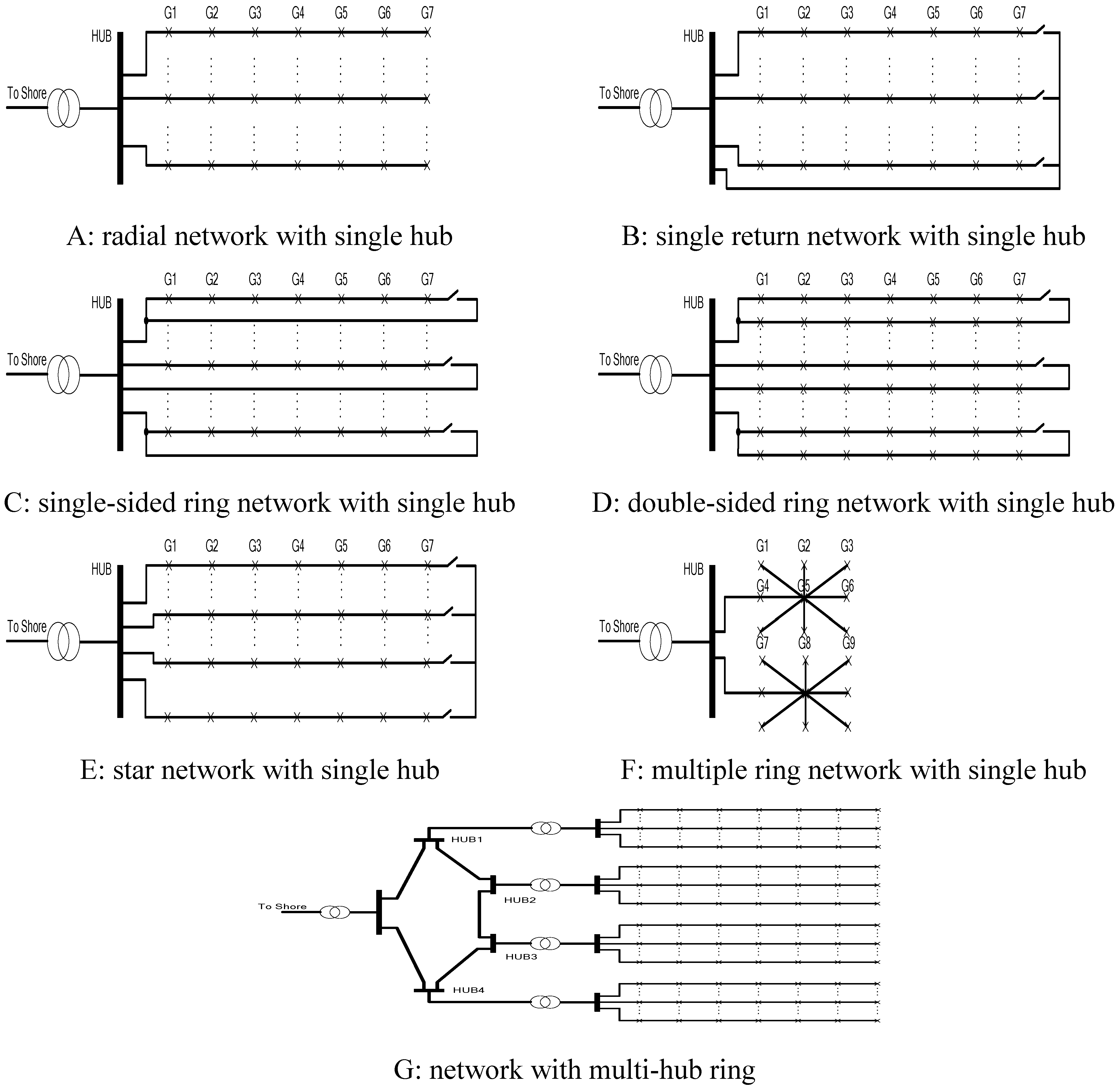
Figure 2 shows possible configurations, namely radial, single return, single-sided ring, double-sided ring, star, multiple rings and multi-hub ring where G1, G2,
etc. represent the wind turbines.
Figure 2.
Overview of different layouts for offshore wind farm collector systems.
Figure 2.
Overview of different layouts for offshore wind farm collector systems.
3.1.1. Radial Layout
This layout is the most straightforward arrangement for a large wind power plant as shown in
Figure 2(A). The main advantage of this layout is the low cable costs achieved by tapered ratings between the wind turbines, as well as the simple control algorithms. However, the downside is the comparatively poor reliability, since cable or switchgear faults at the hub end of the radial cluster may prevent all downstream turbines from exporting for the duration of the fault [
27].
3.1.2. Single-Return Layout
This layout (
Figure 2(B)) enables alternative routes for exporting power during unpredictable faults. It improves the reliability when compared with the simple radial layout. However the additional security comes at the expense of increased cable costs for a given number of turbines [
28].
3.1.3. Ringed Layout
The single-sided ring layout (
Figure 2(C)) employs a redundant path for each string of wind turbines. Similarly to the single-return layout, additional cabling can address some of the security of supply issues. However, this layout also increases the expense of using longer cables and higher cable ratings. The double-sided ring layout (
Figure 2(D)) interconnects the last wind turbine in one string to the last wind turbine in the next string. The redundant circuits are also considered to be in service during normal operation.
The multiple-ring layout shown in
Figure 2(E) interconnects all last wind turbines in strings together. This layout requires the rating of the subsea cable within the string to be larger than the maximum rating of subsea cable in radial design layout so that the full output power of the wind turbines in one of the strings are to be diverted through the other strings during the fault condition. Regardless of the benefits of no redundant cable, the power ratings of the cables are larger [
29].
System reliability issues associated with turbine feeders depend on the electrical arrangement of the feeder. The main issue related to this layout is the cost of cables for different voltages and the cost of additional hubs that require a separate supporting offshore structure. The benefits of reduced losses and enhanced security must be weighted against these additional expenses [
28].
3.1.4. Star Layout
The star design (
Figure 2(F)) is a way to reduce cable ratings and to provide a high level of security for the entire wind farm. Voltage regulation along the cables between wind turbines is also likely to be better in this design. However, there are additional expenses in longer diagonal cable runs and some short sections of higher-rated cabling, but these expenses are not likely to be significant. The more complex switchgear requirement at the wind turbine is the major cost implication [
28,
29].
3.1.5. Network with Multi-Hub Ring Layout
The network with multi-hub ring design (
Figure 2(G)) is a way to lower losses through high voltage collection. Multiple hubs provide greater security, however this layout requires much more expensive extra high voltage cables.
Reference [
30] compares steady-state performance of various collector system designs by using PSS/E simulation software. It is concluded that a single-side ring arrangement has better performance for large offshore wind system as it achieves fewer losses in both normal and contingency operation. It also offers greater security than the radial system. Economic assessment proposed in [
30] shows that ringed designs involve a high investment which is very likely to be a barrier for the deployment of these designs. It is concluded that single-return layout has fewer losses than conceptual ringed options during normal and contingency conditions and has a more competitive cost when compared with the radial option.
4. Electricity Grid Interconnection of Large Wind Farms
Small wind farms and single wind turbines do not influence the system control. The reason is that in case of power system disturbances, the protection system can disconnect them from the power system. However, as the penetration of wind energy increases, wind farms are going to have more responsibility for the system control. Specific technical grid codes specify requirements for the grid interconnection of large wind farms [
19,
20,
21].
4.1. Real Power and Frequency Requirement and Control
Real power control of wind farms aims at maintaining a stable system frequency, preventing overloading of transmission lines, ensuring compliance with power quality standards and avoiding large voltage steps and in-rush currents during startup and shutdown of wind turbines. The real power is typically controlled based on the system frequency. In order to assure a power provision for frequency control, the production of a wind farm can be limited by stall regulation, pitch regulation and controlling the phase angle of the AC side voltage of the wind side converter [
20,
31,
32].
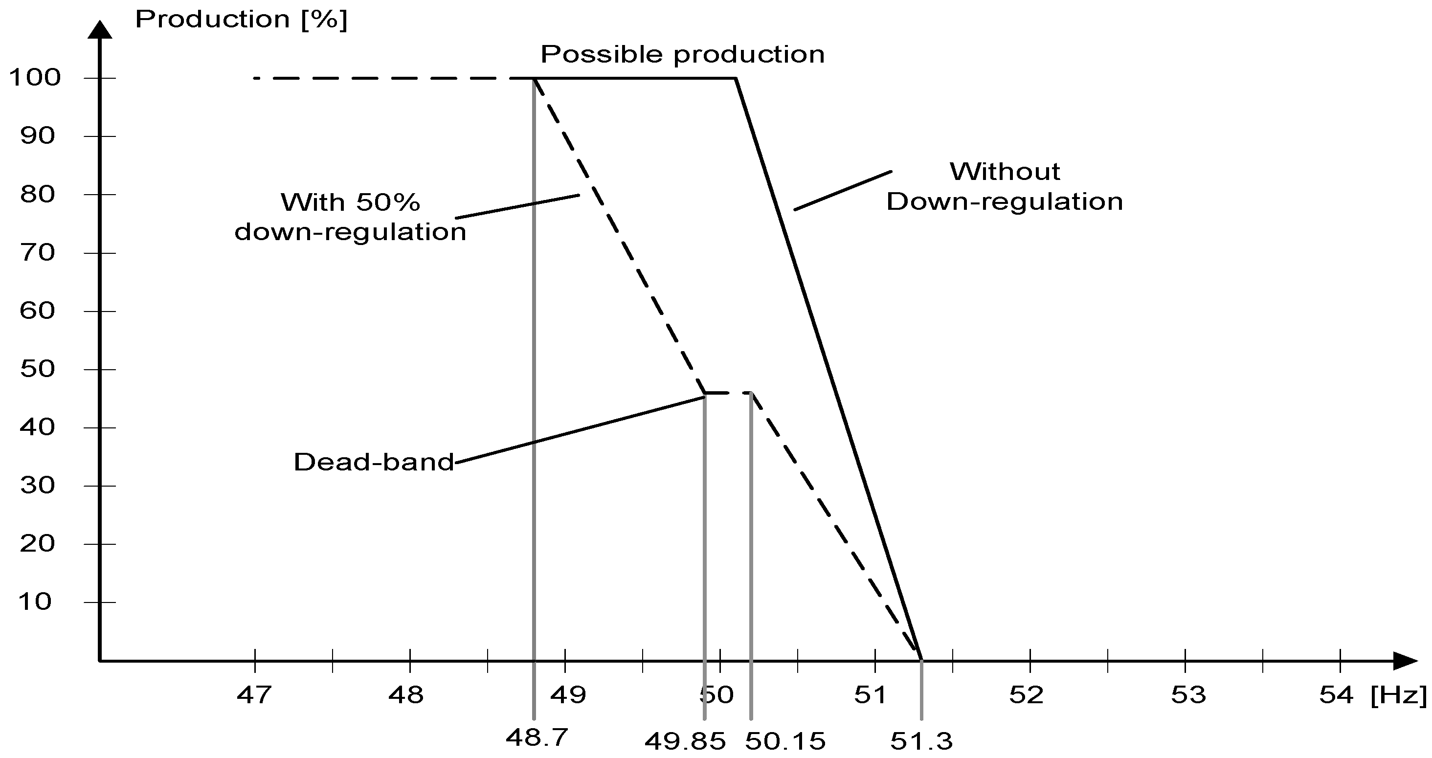
Figure 3 shows a typical characteristic for the frequency control in the Danish grid codes for distribution and transmission; however it might fulfill the frequency control criteria for large scale wind farm in the future as well [
1]. E.ON Grid Code for high and extra high voltage also states that the real power reduces with a gradient 40% when the frequency exceeds 50.2 Hz [
19].
Figure 3.
Frequency control characteristic for the wind turbines connected to the Danish grid [
1].
Figure 3.
Frequency control characteristic for the wind turbines connected to the Danish grid [
1].
However, it may be difficult to increase the output power, since the input power is limited by the wind speed. Large scale energy storage systems may provide an answer. Some fast response energy storage devices such as batteries, pump storage and fuel cells in combination with bidirectional DC-DC converter, are well suited for this purpose although their cost may present a barrier [
33]. The flow (zinc-bromine) battery system which offers two or three times higher energy density, but with the lowest cost per energy stored and delivered over the lead-acid battery, is very promising [
34].
4.2. Reactive Power and Voltage Stability Requirement and Control
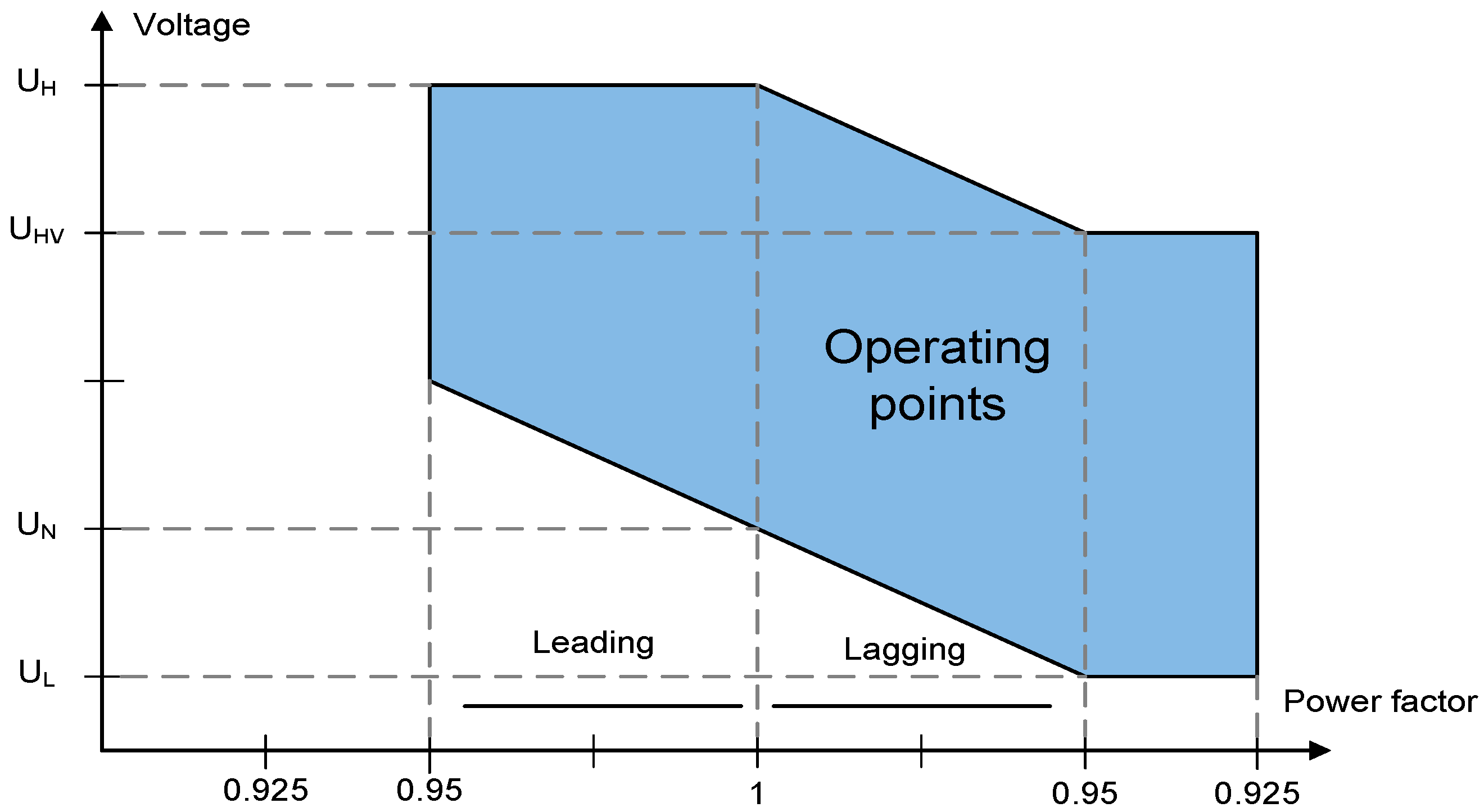
Wind farms are often installed in remote areas and therefore reactive power has to be transported over long distance resulting in power losses. The wind farm shall be equipped with reactive power compensation ensuring that the reactive power is kept within the control band. Recent grid codes demand from wind farms to provide reactive output regulation, often in response to power system voltage variations. E.ON states that the wind power units must provide a reactive power provision as a function of system voltage in the connection point without limiting the active power as shown in
Figure 4 [
19].
Figure 4.
Requirements for reactive power provision of generating units without limiting the active power output in E.ON.
Figure 4.
Requirements for reactive power provision of generating units without limiting the active power output in E.ON.
Voltage variation is the main problem associated with wind power systems, which can be the limiting factor on the amount of possible wind power farms that can be installed. It is required that wind farms must be capable of operating continuously even under rapid voltage changes or voltage jumps, voltage fluctuations, flicker and harmonics. Countries with high penetration of wind power have very stringent demands in order to assure the highest possible power quality of wind power installations [
8].
Wind turbines, especially many of the induction types, can draw large amounts of reactive power from the grid. Depending upon the type of wind turbine generator, the reactive power requirements can be met to some degree by the reactive power capabilities of the wind turbine generators. Locally installed mechanically-switched capacitor banks may compensate the reactive power demand of the induction generators. However this traditional approach controls voltage on a scheduled basis, and works poorly for the wind dependent technology since capacitors are only able to switch fixed amount of reactive powers despite wind energy being variable. Furthermore, once they have been switched off, they must wait for about five minutes until they can be re-energized in order to allow their trapped charge to dissipate. Therefore in most cases additional reactive compensation equipment is needed. In order to provide adequate reactive power support, a mix of static reactive compensation (e.g. switched capacitors) and dynamic reactive compensation (e.g., static VAR compensators (SVCs) and static compensators (STATCOMs)) are often used for large wind farms. SVC typically comprises of bank of individually switched capacitors in conjunction with a thyristor-controlled reactor (TCR). The thyristors are electronically controlled to provide fast-acting reactive power compensation. The amount of reactive power compensation can be varied. However, SVCs are usually not cost effective below 50 MVAr. STATCOMs are based on semiconductor devices such as insulated-gate bipolar transistors (IGBTs), insulated gate commutated thyristors (IGCTs), or gate turn-off thyristors (GTOs) voltage source converter (VSC). STATCOM is connected to the grid to inject or absorb reactive power through coupling inductor. Compared with SVC, STATCOMs provide faster response, less disturbances, and better performance at reduced voltage level [
36]. Reference [
37] states that reactive power compensation can increase the allowed wind power penetration capacity, it is also expected that these devices can improve the steady state voltage stability due to their controllability.
4.3. Fault Ride-Through Requirement and Capability
Wind farms are not required to disconnect, as long as certain voltage and frequency limits are not exceeded. Tripping a large generating plant threatens the power system network stability. Generator tripping results in voltage collapse especially in remote areas. E.ON states that the wind farm should not be disconnected from the grid even if 15% of nominal voltage is reached at the grid connection.
For VSC based HVDC schemes, fault ride-through methods can be grouped according to the techniques used to keep the HVDC transmission voltage at an acceptable level and fast reduction of the wind farm output power:
- (1)
Active current reduction through the wind side converter;
- (2)
Active current reduction of wind turbines through power set point adjustment or frequency control;
- (3)
Voltage reduction in the wind farm through the wind side converter control.
The first method decouples power control after fault detection in the AC line and tries to reduce the active power while keeping the frequency constant. Since the converter based wind turbines are also power controlled, there is an interaction between the wind side converter and the control that may lead to considerable over-voltages in the wind farm grid and mechanical stress for the wind turbines. The strategy employed is to switch the wind side converter to voltage-dependent current limit operation upon the detection of an abnormal DC voltage [
7]. For practical applications, this method seems to be less suitable due to the slow rate of power reduction.
The second method requires communication between the wind side converter, the grid side converter and the wind turbines. When the fault is detected at the grid side, the maximum transferable power is calculated at the grid side, and the result is sent via a communication link to the wind side converter [
1]. One disadvantage of this approach is the high reliability of communication links required between converters and wind turbines. The resulting communication delay limits the speed of the power reduction. Alternatively, it may supersede the communication links of the wind farm by using the wind farm frequency for power reduction. During the fault at the grid side, the wind farm frequency is increased by the wind side converter. The principle of this method is to coordinate the increase of the system frequency, using the wind farm side converter, and reduce the active power from the wind farm upon the detection of abnormal AC frequency [
7]. The main advantage of this approach is that there is no needed for communication with the wind turbines. However, the main disadvantage is that a fast frequency control needs to be implemented for the converter based wind turbines.
The third method does not need communication between the wind side converter and the wind turbines. When a fault occurs, there is a fast voltage reduction in the wind farm grid through the wind side converter voltage control algorithm. This enforces a very fast reduction of wind farm power. This approach deals with the fastest power reduction and the most reliable DC voltage limitation. However, when an abrupt voltage reduction occurs by the wind side converter, doubly-fed induction generators (DFIGs) and fixed-speed induction generators (FSIGs) will result in short-circuit currents with high DC components, which leads to high mechanical stress for the wind turbine drive train and electrical stress for the IGBT modules of the HVDC and DFIG converters [
7].
For LCC based HVDC schemes, a fault ride-through method can be realized by employing a STATCOM to modulate the frequency. This method avoids the need for fast communications. The principle of this method is to increase the frequency of the offshore AC system during grid fault, which once it reaches a certain level; it becomes the signal to the wind farm to reduce its power output [
9,
38].
Many other power system faults can be cleared by disconnecting fast relays to protect the DC transmission system. The challenge of designing this protection is the DC CB which will be discussed in the following section. DC chopper is another method which dissipates all the waste energy in a breaking resistor. Its control is simple and is based on a hysteresis function. The main advantage is that the wind farm is unaffected by the fault [
39].
4.4. Black Start Capability
Black Start is the procedure to recover from a total or partial shutdown of generator. In general, the island operation and the black-start capability are not required for wind power installations. However, the Ireland’s grid code states that the system operator must be notified if the black-start capability is available. In order to accommodate more wind power into the existing grid and to assure the security of the supply, the system operators may require these features from the wind power plants.
With VSC transmission, black start of the wind farm can be achieved relatively easily. During the start period, the grid side converter works as a rectifier and the wind side converter as an inverter, since a small amount of active power is required to supply the power loss of the offshore equipment and network. As the power output from the wind farm increases, the VSC transmission system automatically changes the direction of the power flow and transmits power to the grid.
With LCC transmission on the other hand, a STATCOM is needed during the black start period. The STATCOM DC capacitor is pre-charged from a small auxiliary power supply, e.g., an emergency diesel generator. When the DC capacitor is fully charged, the STATCOM output AC voltage is ramped up to give smooth operation of the transformers and connected filters. The DC capacitor continues to be fed by the auxiliary power supply until the LCC HVDC commences operation. The output of wind turbine is then increased and the HVDC converter changes its control mode to transmit power to the grid.
5. Transmission Systems for Offshore Wind Farm
5.1. DC Cables
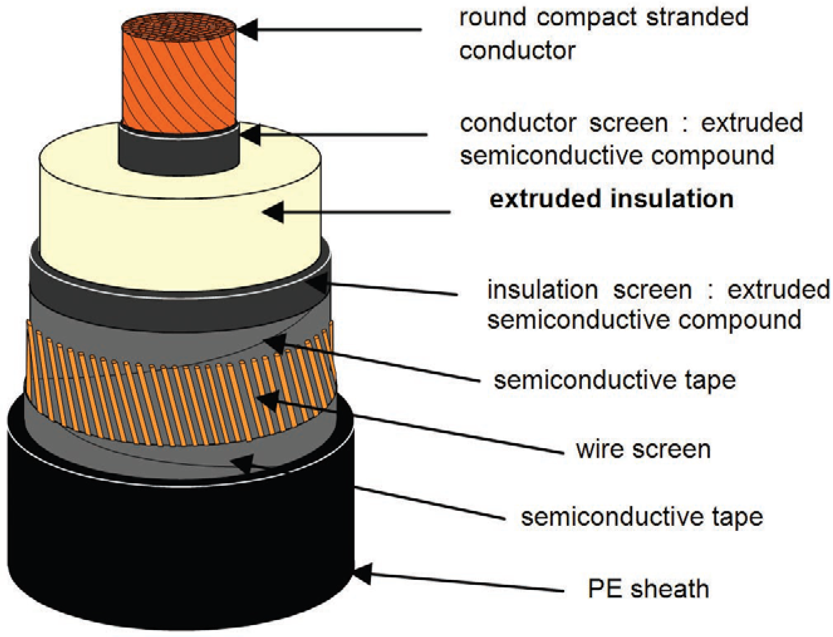
Subsea power cables are critical components of an HVDC power transmission system in any offshore electrical power scheme. For DC cables, the insulation is usually designed to withstand higher voltages when compared to an equivalent AC subsea cable. Offshore transmission cables have a multi-layered structure and are heavily armored. These cables consist of a stranded copper or aluminum conductor surrounded by an insulating layer sandwiched between two semiconductor layers, a wire or tape metallic screen, a moisture barrier layer, and outer protective layers as shown in
Figure 5. It is normally well bonded with both the barrier and protective layers being connected to earth at each end of the cable. The armor of submarine cable is usually of substantial thickness to prevent flux penetration and the armor can be reasonably assumed to be at ground potential at all points along its length [
40].
Figure 5.
High voltage direct current dielectric cable.
Figure 5.
High voltage direct current dielectric cable.
The polyethylene (PE) HVDC cables offer significant advantages over the traditional paper insulated cable types, e.g.:
- (1)
A higher conductor temperature can be used, giving a more compact cable for the same power rating;
- (2)
Lighter moisture barriers can be used, giving a lighter cable;
- (3)
Joining of extruded cables is much simpler and requires less skill;
- (4)
The use of extruded cables avoids the significant long-term environmental hazards associated with oil leaks [
41].
On the other hand, polymeric insulated HVDC cables have a major disadvantage as cable breakdown upon polarity reversal. Avoiding polarity reversal is extremely important for the insulation resistance to DC breakdown. Advanced semiconductor devices as IGBT used in voltage source converter based HVDC transmission can resolve DC cable problems.
Gas insulation (GIL) transmission line is another alternative and uses the gas-insulated line (GIL) conductor. The technology is a continuation of the successful gas insulated switch gear technology used in power transmission. A GIL conductor consists of an outer conductor at earth potential, and an inner conductor that is kept centered by specifically designed spacers. The area in between is filled by SF
6 gas under low pressure that has excellent isolating properties. Only few GIL systems have been built yet, none of which offshore. The high experience with offshore pipe-laying gives rise to belief that the technology could be adapted to submarine circumstances [
23].
The armors of cables also can be different materials from steel to copper. The permeability of steel armor is dependent on the alignment of steel wires since only longitudinal laid wires contribute to the permeability of the cable. In terms of the permeability, the cable with steel armor of µ
r = 100 has less amplitude of resonance along the cable length compared to the cable with steel armor of µ
r = 10 on both AC and DC sides [
3]. Furthermore, when the armor material is changed from steel to copper, the harmonic amplitudes on both the AC and DC sided tend to reduce and the power losses steadily increases as the cable lengths increase, with no obvious resonance, which apparently occurs in the case of the cable with steel armor wires.
5.2. DC Switch
Existing high power CBs are designed for AC systems. These CBs are mechanical devices, using minimum oil, bulk oil, air-blast or SF
6 two pressure types to extinguish the occurring arc [
42]. The use of thermally assisted puffer technology has reduced the operating mechanism requirements for CBs.
The absence of current-zero points in the DC waveform of HVDC CBs makes the interruption process more severe than the case of conventional AC sinusoidal currents [
43]. It has already been confirmed that the H
2 relay gives a large arc voltage and a small time constant for extinction of the arc. Moreover, gas has the characteristic that the interruption performance is improved by increasing its pressure. H
2, N
2, H
2-N
2 and liquid N
2 have been suggested and compared in [
44]. The interruption performance of H
2 is superior to others, because the limit of the interruption voltage was high and the arcing time was short.
Alternatively, active CBs which include semiconductor devices are often used because they are able to turn-off a current directly and demagnetize the grid inductance. The different DC CBs topologies can be divided into three categories, namely, conventional hybrid CB, solid-state CB and mechanical CB with snubber circuit.
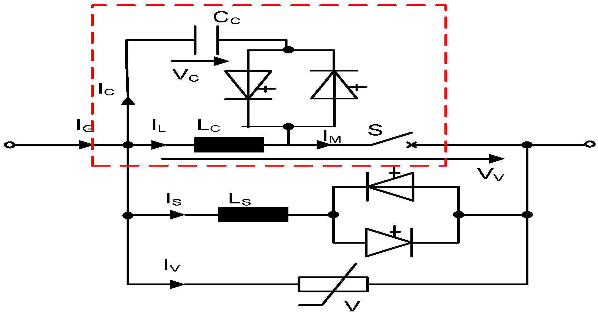
5.2.1. Classical Conventional Hybrid CB
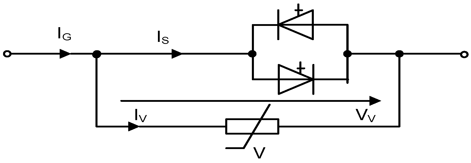
This method consists of two switching technologies: mechanical systems and semiconductor devices. One classic solution is shown in
Figure 6. During normal operation, the mechanical breaker S conducts the current. As soon as a failure is detected, the current is commutated to the semiconductor by opening the mechanical switch. The semiconductors conduct the current until the mechanical breaker is able to block the full voltage. At this point, the semiconductors are turned off. Due to the stored energy in the line inductor, the voltage will increase very fast, until the varistors start to conduct and clamp the voltage to demagnetize the grid inductance. The advantage of this system is that it has very low on-state loss, and the current can be turned off independently from a natural zero crossing. However, the switching speed strongly depends on the mechanical parts of the system.
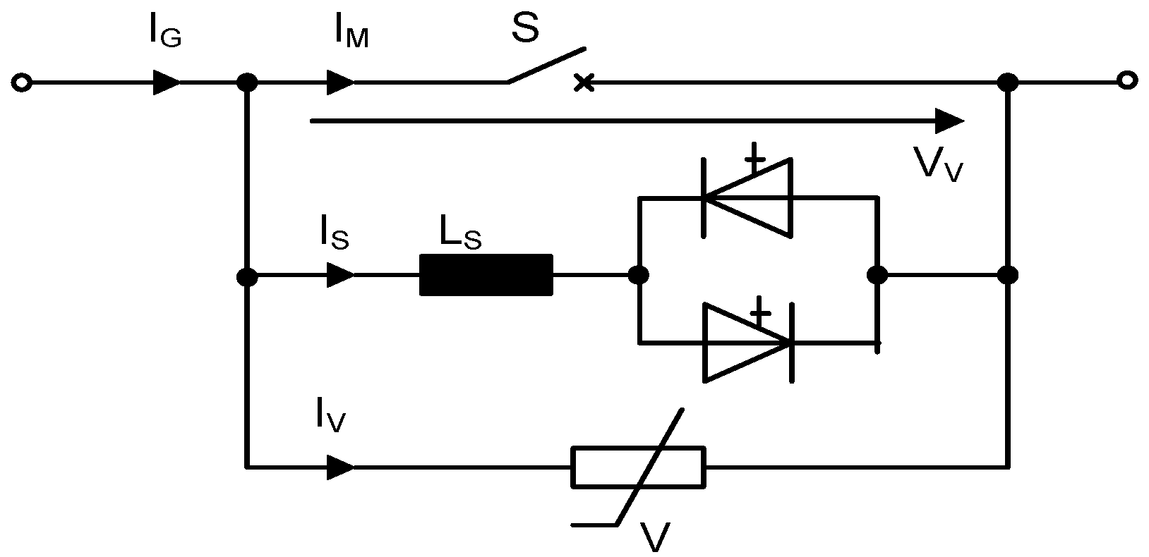
5.2.2. Classical Conventional Hybrid CB with Forced Commutation
To increase the opening speed of the CB, a large amount of energy is needed. As a consequence, one effective way to reduce the delay time is to avoid the arc inside the mechanical CB. Therefore, a forced commutation circuit for a mechanical CB was developed which commutates the current to the parallel path before the mechanical CB is opened. Reference [
4] states that the maximum current could be reduced by 30% which leads to a reduction of the needed switching power in the parallel path.
Figure 6.
Conventional hybrid CB.
Figure 6.
Conventional hybrid CB.
Figure 7.
Conventional hybrid CBs with forced commutation method.
Figure 7.
Conventional hybrid CBs with forced commutation method.
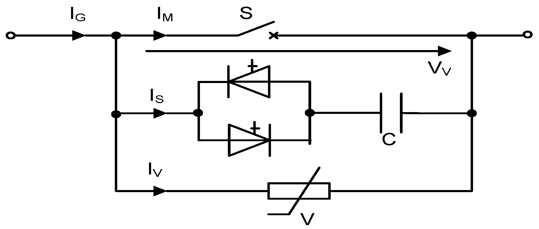
5.2.3. Solid-State CB
Based on the solution presented in [
45] a solid-state CB can substantially increase power quality and is capable of interrupting faults in medium-voltage grids with multiple energy sources. Gate-commutated thyristor (GCT) is preferred in this application due to the only interest of the on-state losses. The topology is depicted in
Figure 8. During the on-state operation, the current flows through the GCTs. As soon as the failure is detected, the semiconductors are turned-off and the voltage is increased very fast until the varistor starts to conduct. Compared with the other topologies, the solid-state solution offers the best performance, since no mechanical parts are needed. As a consequence, the maximum current and the turn-off are both reduced significantly. The major disadvantage of this solution is the on-state losses which are significantly higher compared to the traditional methods.
Figure 8.
Solid-state CB.
Figure 8.
Solid-state CB.
Figure 9.
Mechanical circuit breaker with turn-off snubber.
Figure 9.
Mechanical circuit breaker with turn-off snubber.
5.2.4. Mechanical CB with Turn-off Snubber
The mechanical CB is not able to turn off a DC current and has no cooling equipment to extinguish an arc. Consequently, an additional circuit is needed to detect and turn off the mechanical CB. In contrast to a normal snubber circuit, additional thyristors are used. The reason for this is that the inductance will be demagnetized by the varistor and with a dropping current; the voltage will also be decreased. This leads to commutation of the current back to the capacitor which will lead to a negative voltage across the inductor and therefore a negative current. Consequently, an oscillation occurs and leads to a turn-off failure. By using the thyristor, this effect is avoided because they turn off as soon as the current reduces to zero. In contrast to other topologies, semiconductors are not needed and from the cost point of view, it is the most attractive solution for voltage level up to 20 kV [
4]. However, several varistors and commutation capacitors are needed which strongly depend upon the maximum turn-off current.
6. Conclusions
In this paper, DC system technologies for large scale integration of wind energy with electricity grid are discussed. With the increasing levels of wind farm penetration, grid connection codes have posed new challenges to wind farm design, development, operation and control. Meeting these requirements has become a major issue of large scale wind energy generation even during a large grid disturbance or fault condition. A comparison of various conceptual designs for the electrical collector system options in terms of their losses and economics are also presented. Radial layout compared with other configurations, has the lowest cable cost, while ringed-design are superior in terms of reliability and power losses during normal operation.
Multi-layered subsea power cable is critical for electricity transmission from large offshore wind farms. PE cables are preferred to impregnated paper insulated because of their high conducting temperature, light moisture barriers and simple joint method. Another critical factor for electricity transmission is the DC CB. Different gases are compared to improve the interruption performance of mechanical switches. H2 is superior to others because it has high interruption voltage limit and short arcing time. Other active CBs are also presented. For medium voltage application a mechanical system with a proper designed snubber circuit should be used, while for high voltage application a solid-state CB is preferred.
