Article

Performance Improvement of a Portable Electric Generator Using an Optimized Bio-Fuel Ratio in a Single Cylinder Two-Stroke Engine

by
Norhisam Misron
1,*,
Suhairi Rizuan
1,
Aravind Vaithilingam
1,*,
Nashiren Farzilah Mailah
1,
Hanamoto Tsuyoshi
2,
Yamada Hiroaki
2 and
Shirai Yoshihito
2
1
Department of Electrical & Electronic Engineering, Faculty of Engineering, Universiti Putra Malaysia, Serdang, Selangor 43400, Malaysia
2
Department of Biological Functions and Engineering, Graduate School of Life Science and Systems Engineering, Kyushu Institute of Technology, Kyushu 804-8550, Japan
*
Authors to whom correspondence should be addressed.
Energies 2011, 4(11), 1937-1949; https://doi.org/10.3390/en4111937
Submission received: 8 September 2011 / Revised: 27 October 2011 / Accepted: 31 October 2011 / Published: 10 November 2011

Abstract

:
The performance of an electrical generator using bio-fuel and gasoline blends of different composition as fuel in a single cylinder engine is presented. The effect of an optimized blend ratio of bio-fuel with gasoline on engine performance improvement and thereby on the electrical generator output is studied. Bio-fuels such as ethanol, butanol and methanol are blended with gasoline in different proportions and evaluated for performance. The effects of different bio-fuel/gasoline blending ratios are compared experimentally with that of the gasoline alone using the output power developed by the electric generator as the evaluation parameter. With a composition of 10% ethanol–gasoline, the engine performance is increased up to 6% and with a blending ratio of 20% butanol–gasoline the performance is increased up to 8% compared to the use of 100% gasoline. The investigations are performed on a portable generator used in palm tree harvesting applications.

1. Introduction

Gasoline-based engines have provided excellent performance over the past decades and are frequently used in agricultural systems. Due to the increase of oil prices and oil scarcity, there is the need to look for alternative energy resources. Most industrial process scenarios today are staged around the development of high performance economical machine tools to increase productivity. In the context of engine performance improvement and management researchers continue to study the effects of the usage of conventional gasoline blended with alternative fuels on the engines’ performance [1,2,3,4,5,6]. Recent advancements in rare earth magnets have paved the way for simultaneous research into replacing conventional generators with high power generators that help increase the performance of the engine, and heavier conventional engines with battery setups are being replaced by lightweight portable electric generators, making the use of a portable electric generators more practical compared to the battery setups for outdoor applications, especially in the agricultural industry. The agricultural wastes that are processed as bio-fuels blended with gasoline make it a more economical, viable and environmental friendly fuel for engine performance [1]. Malaysia is the largest palm oil producer and exporter in the World [7,8]. Along with the economic profitability, the industry also generates large amounts of waste such as Empty Fruit Bunch (EFB) [9,10], that can be transformed into value-added bio-fuels such as bio-ethanol [9], bio-butanol [10] and bio-methanol [11,12], that can easily be blended with gasoline. These mixtures are best suited for use in the present fuel distribution system of existing engines [13,14] that are used as prime mover for electric generators in harvesting applications. Numerous studies on blended bio-fuel and gasoline as engine fuel are under way for economic reasons and to provide a less combustion exhaust alternative for gasoline. Most of them reveal that bio-fuel gasoline blending increases the engine performance and reduces the emissions of carbon monoxide (CO), nitrogen oxides (NOx) and hydrocarbons (HCs). Muharrem et al. [2] studied the effect of ethanol–gasoline (E5, E10) and methanol–gasoline (M5, M10) fuel blends on the performance and combustion characteristics of a spark ignition (SI) engine. The results indicated that when alcohol–gasoline fuel blends are used, the brake specific fuel consumption is increased. Kelly et al. [3] tested three blends of gasoline with ethanol at various ratios and reported that with the use of 85% ethanol the emissions of HC and CO were reduced considerably. Fikret et al. [4] analysed a spark-ignition engine using ethanol–gasoline blends. It is inferred from that study that a dual fuel system can be serviceable after making simple modifications on the carburetor and that these modifications do not cause complications in the operation of the carburetor system. For better engine performance a high compression ratio is often desirable, as it allows the engine to extract more mechanical energy from a given mass of air-fuel mixture due to its higher thermal efficiency. However the higher compression ratio makes gasoline engines using low octane-rated fuel prone to engine knocking by building up the cylinder pressure, thereby reducing tremendously the efficiency or even damaging the engine. Mustafa et al. [5] studied experimentally the effect of unleaded gasoline (E0) and unleaded gasoline–ethanol blends (E50 and E85) on engine performance and emissions of pollutant gases in a single cylinder four-stroke spark-ignition engine at two compression ratios (10:1 and 11:1). The results showed that the addition of ethanol to unleaded gasoline increased the engine torque, the power and the fuel consumption and reduced the CO, NOx and HC emissions. It is reported that ethanol–gasoline blends allow increasing the compression ratio without occurrence of knocking. Bahattin et al. [6] in his study used gasoline blended with methanol at a high compression ratio to increase performance and decrease emissions in a single-cylinder engine. Initially, the engine with a compression ratio 6:1 was tested at full load and at various speeds with gasoline and methanol. Then, the compression ratio was gradually raised to 8:1 and 10:1. The results showed a considerable decrease in CO, CO2 and NOx emissions without any noticeable power loss compared to using methanol at the compression ratio of 6:1. By increasing the compression ratio from 6:1 to 10:1 with methanol, the engine power and brake thermal efficiency increased up to 14% and 36%, respectively. Moreover, CO, CO2 and NOx emissions are reduced by about 37%, 30% and 22%, respectively. In none of the work reported by other researchers was the electrical power output from the generator used as an evaluation parameter for the engine performance, nor has a performance comparison of blending ethanol, butanol and methanol with gasoline and testing with electrical loading been reported. Many of them use ethanol-gasoline [4] and methanol with gasoline [6] in their studies. The purpose of this work was to test the performance of blended bio-fuel (ethanol, butanol, and methanol) and gasoline as fuel in the single cylinder two stroke engine of a portable electric generator and compare the generator performance with that obtained using gasoline alone as fuel. A standard single cylinder two stroke engine which is readily available in the market is used [14] in this study. This type of engine is the most commonly used prime mover for the portable electric generators that power harvesting machines in the agricultural industry use. Three types of bio-fuel–gasoline combinations are used for the engine and the output electric power is experimentally evaluated as a performance parameter. The effect of various compression ratios on the performance of the engine due to the use of octane number rich blending fuels such as ethanol, butanol and methanol will be reported in future work.

2. Experimental Setup

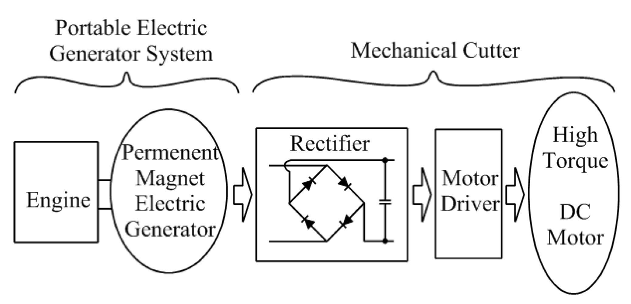
2.1. Portable Harvesting System

In the agricultural industry, portable lightweight electric generators with continuous power supply capability are widely used to power harvesting systems. For this purpose, small size engines [14] with a high power density permanent magnet type electric generator [15] are used. The development of these high power density generators is documented in [15,16,17]. The output power generated by this engine-generator combination is used to supply power to a high torque brushless DC motor, which in turn is used as the load unit for the harvesting machines. Figure 1 shows the configuration of a typical system with a mobile electric generator and a mechanical cutter. The first part of the system is the mobile electric generator, which consists of a gasoline engine and a high power permanent magnet type electric generator, while the second part, which is the mechanical cutter, consists of a rectifier, motor driver and single phase high torque brushless DC motor with a mechanical gear arrangement. As the gasoline engine coupled to the electrical generator rotates electrical output power is generated, depending upon the operating speed of the engine. The motivation of this paper is to present the possible performance improvement of the electrical generator by using an optimized bio-fuel gasoline ratio mixture in the engine. Once there is sufficient improvement in performance of the electrical generator output the performance of the loading unit coupled to the generator is improved. First the mechanical performance of the engine is tested with various fuel ratio combinations under conditions ranging from no load to full load. The permanent magnet generator is then coupled to the prime mover and the electrical performance is evaluated by means of a resistance grid bank of sufficient capacity to accommodate its maximum rated capacity.
Figure 1. Configuration of a portable harvesting system.
Energies 04 01937 g001
This experimental evaluation is carried out prior to connecting to the actual load element which is the mechanical cutter. Several load tests of the engine with different fuel ratio combinations are preceded by a sufficient number of runs at no load and partial load to insure improvement of generator performance. Load test readings are taken over a period of time sufficient to obtain average values. With this demonstrated improvement in the generator performance, the mechanical cutter segment performance is improved for real time portable applications like the harvesting systems described in this research. These optimized fuel combinations with the proposed generator combinations could be applied to various other portable real time applications.

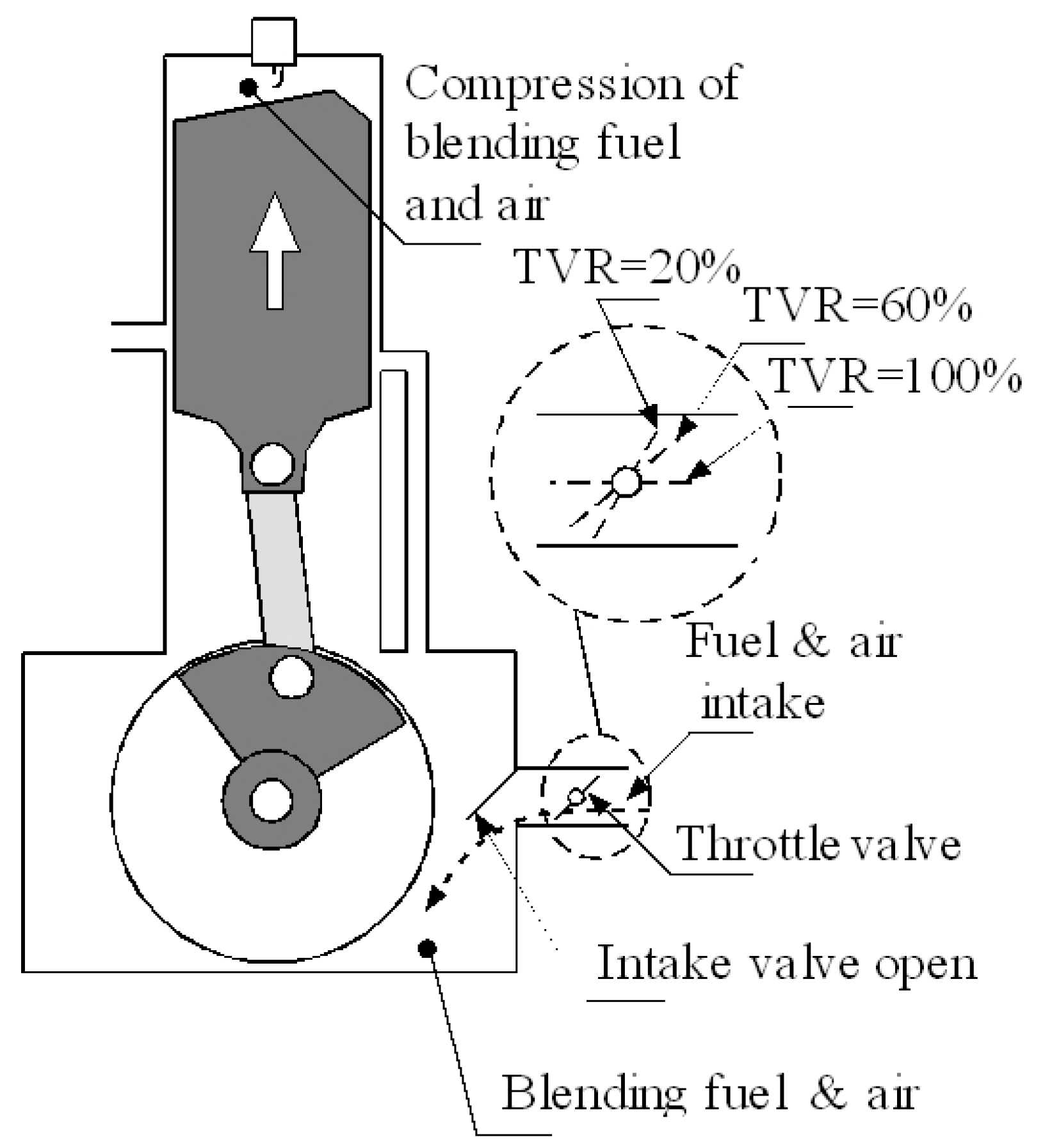
2.2. Engine Characteristics

A 25 cc single cylinder two stroke engine (KM 85, Stihl) which weighs about 4 kg and can generate a maximum power of 950 W at 8500 rpm was used in this study. The KM85 engine complies with the ISO 8893:1997 standards and is typically used in forest machinery, particularly for portable brush-cutters and grass trimmers [14]. Table 1 shows the specifications of the engine used for this study.
Table 1. Single cylinder two stroke engine (KM 85) specifications.
ItemValue
Displacement (cm3)25.4 cm3
Bore (mm)34 mm
Stroke (mm)28 mm
Engine power (hp)950 W (1.3 hp) at 8500 rpm
Idle Speed (rpm)2800 rpm
Rated cut off speed (rpm)10500 rpm
Ignition systemSpark plug
Compression ratio7:1
The cut off speed of this engine is at 10,500 rpm at a compression ratio of 7:1. The speed of the engine can be varied by a Throttle Valve Ratio (TVR) adjuster, as shown in Figure 2. The higher the TVR value, the more fuel and air is taken in from the engine carburetor.
Figure 2. Typical single cylinder two stroke engine with valve adjuster.
Energies 04 01937 g002

2.3. Generator Structural Features

The structure of the single phase eight slot permanent magnet electric generator with external stator and internal rotor and its basic flux path is shown in Figure 3.
Figure 3. Structural features and flux flow of the portable electric generator [15].
Energies 04 01937 g003
The electrical generator design is based on previous research work by the authors on the development of a high power permanent magnet assisted generator [15,16,17]. The eight poles of the rectangular shaped NdFeB rare earth permanent magnets are embedded in the rotor to facilitate high speed applications. The rotor and stator are made from a magnetic material such as soft steel (SS400) while the shaft is made from a non-ferromagnetic material (SUS403). The generators are designed for use as portable generators to supply electrical power for agricultural applications and are designed for single phase operation with the coil connected in series to produce a variable ac voltage. The output power of the generator is converted through a rectifier and filter before supply to a typical load application. Table 2 shows the structural specifications of the electrical generator used in this study.
Table 2. Electric generator specifications.
ParameterValue
Rated power (W)450 W
Rated voltage (V)100 V
Rated current (A)4.5 A
Maximum Speed (rpm)10,500 rpm
Armature Resistance (Ω)0.8 Ω
Armature Inductance (mH)4 mH

2.4. Voltage and Torque Equations

The voltage induced in the coil for the electric generator relates to the flux reversal and is based on Faraday’s Law that states “the induced voltage in any of the closed circuit is equal to the change of the magnetic flux linkage by the circuit with respect to time”. Therefore, as the rotor rotates continuously it produces a rotating magnetic field in the stator and thereby the voltage is induced by the winding coil at the stator yoke due to its rate of change of flux. When these windings are connected to the load a current as indicated in Equation (2) flows. Proportionately, the torque generated is given by Equation (4). The current and torque value depend on the load resistance value as shown in Equations (2) and (5). With a constant generated voltage and a smaller load resistance, a higher torque is generated as shown in Equation (5):
EG = 4.44 f NΦ  [V]
I = EG / Rt    [A]
Rt = Ra + Rext   [Ω]
τ = KT i      [Nm]
τ = KT(EG / Rt)   [Nm]
where EG is the generated rms voltage in (V), f is frequency of the electric generator in (Hz), N is the number of turns, Φ is the flux through coil winding in (Wb), I is current flow in load circuit in (A), Rt is effective resistance in (Ω), Ra is the armature resistance in (Ω), Rext is the external resistance in (Ω), τ is torque in (N·m) and KT is the torque constant (N·m/A).

3. Fuel Characteristics and Measurement Setup

3.1. Fuel Characteristics

It has been well documented in the literature that a high compression ratio gives better engine performance if a bio-fuel-gasoline blended fuel with a high octane number, normally called Research Octane Number (RON), is used. This octane rating is a measure of the self-ignition capability of a gasoline or liquid petroleum fuel. The higher the number, the less likely an engine is to pre-ignite and suffer damage. Each fuel has a different octane number (RON) value, with methanol being at 133 and butanol having the lowest octane number of 92. The octane number for gasoline is 95.
The different blending ratio values directly affect the engine performance. The main measured parameter in this study is the blending ratio of the bio-fuel such as ethanol (E), butanol (B), methanol (M) with the gasoline (G). The engine performance is observed from the output electrical power generated by the electric generator. Table 3 shows the properties of the fuel components that are investigated in this study [13].
Table 3. Characteristics of test fuels used in this study [13].
Fuel PropertyEthanoln-ButanolMethanolGasoline
Chemical formulaC2H5OHC4H9OHCH3OHCH1
Specific gravity 15/15 vC0.78940.80970.79130.7430
Lower heating value (MJ/kg)26.8332.0120.0842.9
Stoichiometric air–fuel ratio8.9411.126.4314.51
Energy density of a Air–fuel mixture (MJ/kg)2.6992.6412.7502.769
Latent heat of vaporization (kJ/kg)8385841098349
Octane number (RON)1299213395

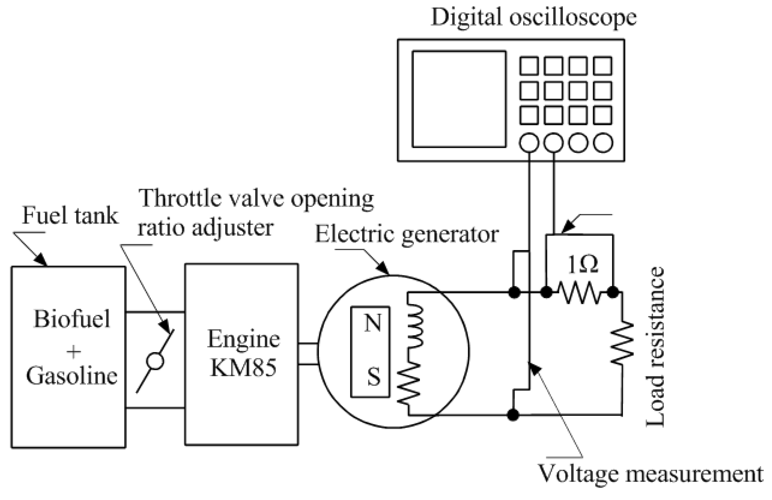
3.2. Experimental Measurement Setup

The mechanical power produced by the engine is converted to electrical power by the electric generator. The electrical output power by the electric generator can be calculated by using Equation (6). The integration of the product of current and voltage waveforms from measurement give the real power produced by the electric generator:
P E = 1 T 0 T ( i v ) d t [ W ]
where PE is the generated electrical power in [W], v is the induced voltage in [V] and i is current in the system in [A] and T is time in [s]. Figure 4 shows the experimental setup for the measurement of the voltage and current with resistive load varying from 10 Ω to 100 Ω.
Figure 4. Experimental measurement setup.
Energies 04 01937 g004
The voltage and current waveforms are recorded using a digital oscilloscope and the real power is calculated using Equation (6) with resistive electrical load connected to the generator. This electrical load is used to vary the torque value generated by the electric generator. A set of electrical load resistance banks is used to evaluate the performance of the engine with the different fuels. The throttle valve of the engine is adjusted to control the fuel air flow and also at the same time the speed of the engine. Table 4 shows the measurement parameter ranges of the electrical load, the TVR ratio and the various blending ratio used in this investigation. The electrical load is varied from 10 Ω to 100 Ω and the TVR value is varied from 20% to 100%. The gasoline ratio is changed from 90% to 60% with the bio-fuel ratio changing from 10% to 40%. For each blending ratio value, the voltage and current waveform are measured and the real power is determined.
Table 4. Measurement parameter ranges.
Electrical Load
(Resistive Load)
Throttle Valve Ratio (TVR)Blending Ratio
G (90% ~ 60%) E (10% ~ 40%)
Rext = 10 Ω ~ 100 Ω20% ~ 100%G (90% ~ 60%) B (10% ~ 40%)
G (90% ~ 60%) M (10% ~ 40%)
* G-gasoline, E-Ethanol, B-Butanol, M-Methanol.

4. Results and Discussion

4.1. Voltage and Current Waveforms

Figure 5 shows the voltage waveform in phase with the current waveforms as the load is a purely resistive load. A resistive load bank is used to experimentally study the performance characteristics of the electrical generator with different fuel combinations in the engine.
Figure 5. Electrical characteristics for load resistance of 20 Ω. (a) TVR 20% at load resistance 20 Ω; (b) TVR 80% at load resistance 20 Ω.
Energies 04 01937 g005
The throttle valve ratio adjuster helps to adjust the fuel-air combustion inside the engine chamber and is one of the factors that help to increase the power output. The power that is generated for 20% TVR in Figure 5a is 252 W and for 80% TVR in Figure 5b is 398 W for a 20 Ω electrical load. The current frequency for 20% TVR is 390 Hz while for 80% TVR is 630 Hz. With the TVR at 80%, more fuel is injected into the engine contributing to increase of engine speed. The electrical characteristics are derived from the different load settings with different TVR values.

4.2. Engine Speed and Power Generation

The relationship between the engine speed and the power generation as described in [15,16,17] is used in this research. As seen in Figure 6, the output power of the electric generator is directly proportional to the speed of rotation. At higher speeds, the generated voltage is increased and the output power is proportionately increased for a constant electrical load. However for a higher load resistance value, the output power decreases due to the reduced current that flows in the load. It can be inferred from Figure 6 that the maximum output power generated by the electrical generator is about 400 W at the maximum speed of 10,500 rpm.
Figure 6. Relationship between electrical output power and engine speed.
Energies 04 01937 g006

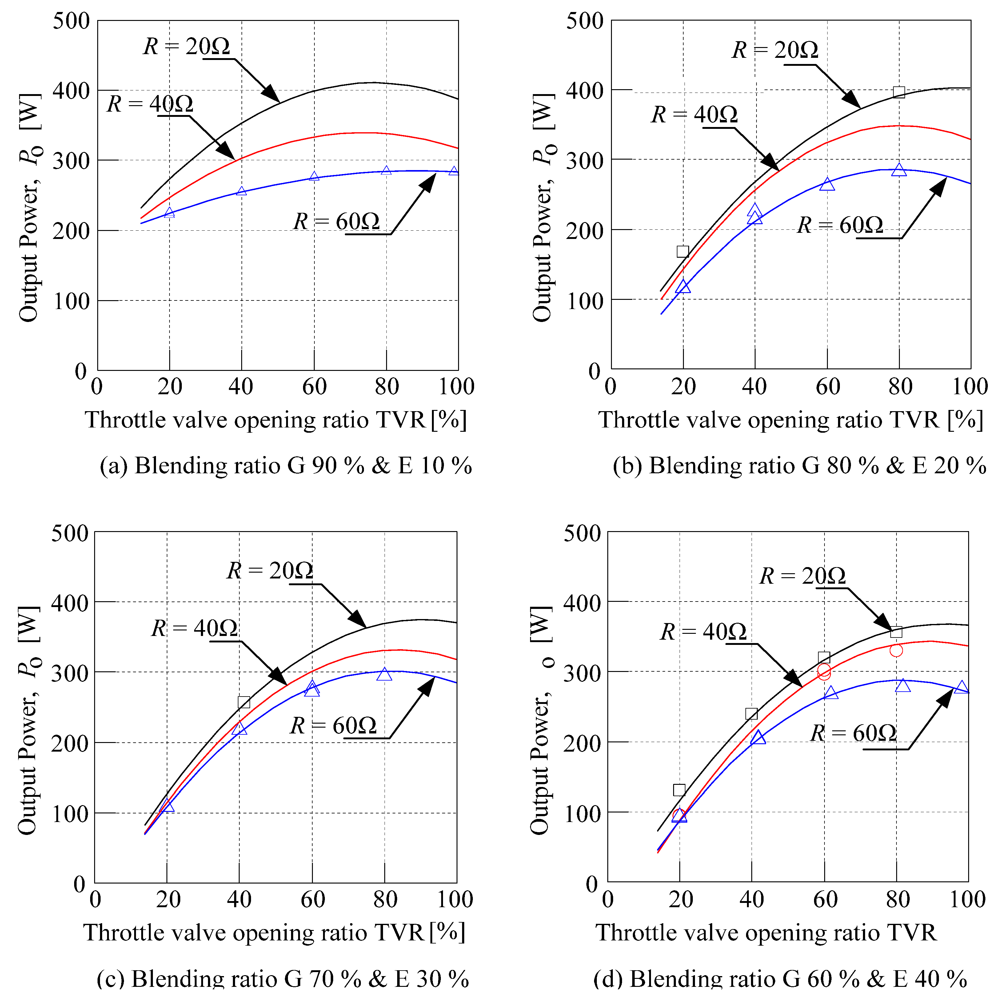
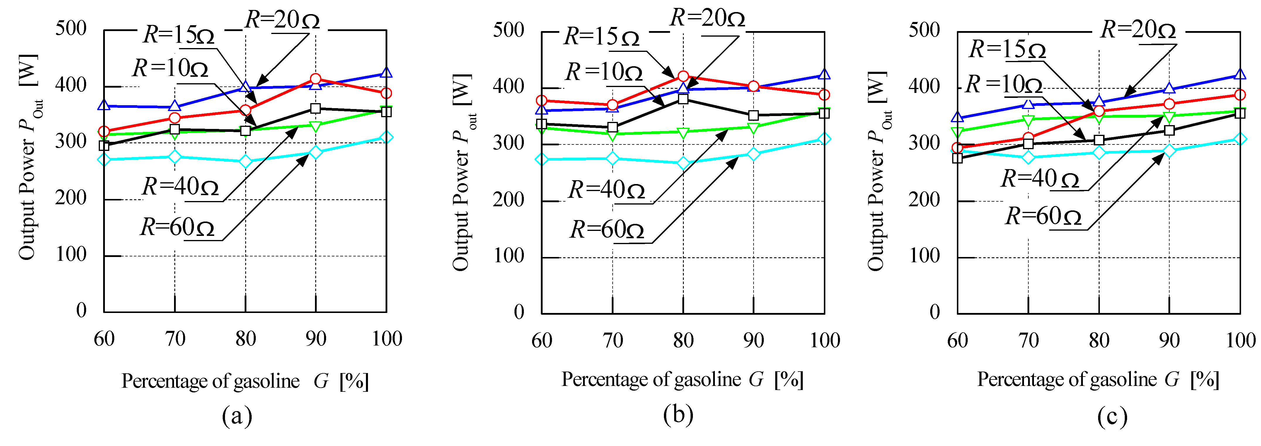
4.3. Effect of Bio-Fuel-Gasoline Blending Ratio on Output Power of Electric Generator

Figure 7 shows the characteristic output power when the TVR is increased up to 100% with 20% incremental value using gasoline-ethanol blend. The output power increases proportionately up to 60% TVR value. But, for the TVR value from 80% and 100% the output power values are almost constant. Similar output power characteristics are observed when operated with different load resistance values. From the observation, it can be inferred that the optimal performance of the engine is achieved for a TVR of 80%. It is evident from [5,6] that a higher compression ratio helps to achieve better performance with lower emissions. The higher compression ratio thereby increases the fuel consumption efficiency and increases the performance of the electrical power output. Figure 7 also shows that for higher load resistances of 60 Ω and 40 Ω the generator does not exhibit any significant decrease of the maximum output power, even with different gasoline-ethanol blending ratios. However for the lower load resistance value as 20 Ω, the maximum output power shows significant changes. With a higher percentage of ethanol ratio in the blended fuel the maximum output power is reduced. For instance, the output power for blending ratio G90%-E10% is 405 W, which is 11% higher than the blending ratio G60%-E40%. The correlation of the blending ratio is highly significant with lower resistance value compared to that of higher load resistance value. For higher load resistance 40 Ω and 60 Ω, the effect of blending ratio is difficult to observe for all types of blended bio-fuel and is less significant.
Figure 7. Effect of throttle valve ratio (TVR) on the generator output power. (a) Blending ratio G 90% & E 10%; (b) Blending ratio G 80% & E 20%; (c) Blending ratio G 70% & E 30%; (d) Blending ratio G 60% & E 40%.
Energies 04 01937 g007
Experiments are performed with different blending ratios of bio-fuel such as ethanol, butanol and methanol with gasoline for lower load values of 10 Ω, 15 Ω and 20 Ω and the results are shown in Figure 8. For a typical load resistance value of 20 Ω the output power shows similar characteristics, irrespective of the bio-fuel used in the experiments. The output power observed for load values of 10 Ω and 15 Ω for the butanol-gasoline blends percentage of 70% to 90% shows variations in the characteristics (Figure 8b) because of the saturation of the generator. Because of the machine saturation the output power drops at 90% blending. The methanol-gasoline blend shows (Figure 8c) the same characteristics for the load resistance value of 15 Ω and 10 Ω. However, the ethanol-gasoline blends and butanol-gasoline blends show very interesting effects for load resistances of 15 Ω and 10 Ω. The output power generated for the ethanol-gasoline blend, for a blending ratio of G90%-E10% is seen to be the maximum. The output power is 6% higher compared to 100% gasoline. This behavior is observed with a load resistance of 15 Ω and 10 Ω. Furthermore, for butanol-gasoline blends, the output power is maximum when the blending ratio is G80%–E20%, where the output power is 8% higher corresponding to 100% gasoline. This behavior is also observed with load resistances of 15 Ω and 10 Ω.
Figure 8. Electrical characteristics of bio-fuel/gasoline with different blending ratios: (a) Ethanol; (b) Butanol; (c) Methanol.
Energies 04 01937 g008

5. Conclusions

An evaluation of the effects of bio-fuel-gasoline blends on the generator performance of single cylinder two stroke engines is performed and reported. As reported in [2,4,5] alcohol–gasoline fuel blends improve the brake specific fuel consumption. As the fuel consumption is improved, the electrical power output performance is increased. In this research the engine performance is investigated by measuring the output power generated by an electric generator that is coupled to the engine. With the load resistance of 15 Ω and with a blending ratio of 10% ethanol–90% gasoline the performance of the engine is increased up to 6% more than by using 100% gasoline alone as fuel. For a blending ratio of 20% butanol-80% gasoline, the engine performance is increased by 8% more than when using 100% gasoline as fuel. In conclusion, the engine performance increases compared to using 100% gasoline as fuel for a typical load condition with certain bio-fuel and gasoline blends, especially when high load torque is required.

Acknowledgements

The authors would like to acknowledge the financial and technical support by the Japan New Energy Foundation, the Universiti Putra Malaysia (UPM), the Kyushu Institute of Technology (KIT) and the Malaysia Palm Oil Board (MPOB) towards this research work.

References

  1. Yusoff, S. Renewable Energy from Palm oil Innovation on Effective Utilization of Waste. J. Clean. Prod. 2006, 14, 87–93. [Google Scholar] [CrossRef]
  2. Eyidogan, M.; Ozsezen, A.N.; Canakci, M.; Turkcan, A. Impact of alcohol–gasoline fuel blends on the performance and combustion characteristics of an SI engine. Fuel 2010, 89, 2713–2720. [Google Scholar] [CrossRef]
  3. Kelly, K.J.; Bailey, B.K.; Coburn, T.; Clark, W.; Lissuk, P. Federal test procedure emissions test results from ethanol variable-fuel vehicle Chevrolet luminas. In Proceedings of the Society for Automotive Engineers International Spring Fuels and Lubricants Meeting, Dearborn, MI, USA, 6–8 May 1996.
  4. Yüksel, F.; Yüksel, B. The use of ethanol–gasoline blends as a fuel in an SI engine. Renew. Energy 2004, 29, 1181–1191. [Google Scholar] [CrossRef]
  5. Koc, M.; Sekmen, Y.; Topgu, T.; Yucesu, H.S. The effects of ethanol–unleaded gasoline blends on engine performance and exhaust emissions in a spark-ignition engine. Renew. Energy 2009, 34, 2101–2106. [Google Scholar] [CrossRef]
  6. Bahattin Celik, M.; Ozdalyan, B.; Alkan, F. The use of pure methanol as fuel at high compression ratio in a single cylinder gasoline engine. Fuel 2011, 90, 1591–1598. [Google Scholar] [CrossRef]
  7. Economics and Industrial Division. Malaysian Palm Oil Board World Oil & Fats 2008. Available online: http://econ.mpob.gov.my/economy/annual/stat2008/ei_world08.htm (accessed on 13 May 2011).
  8. Sumathi, S.; Chai, S.P.; Mohamed, A.R. Utilization of oil palm as a source of renewable energy in Malaysia. Renew. Sustain. Energy Rev. 2008, 12, 2404–2421. [Google Scholar] [CrossRef]
  9. Mumtaz, T.; Yahaya, N.A.; Abd-Aziz, S.; Rahman, N.A.; Yee, P.L.; Shirai, Y.; Hassan, M.A. Turning waste to wealth-biodegradable plastics polyhydroxyalkanoates from palm oil mill effluent a Malaysian perspective. J. Clean. Prod. 2010, 18, 1393–1402. [Google Scholar] [CrossRef]
  10. Fatih Demirbas, M.; Balat, M.; Balat, H. Biowastes-to-bio-fuels. Energy Convers. Manag. 2011, 52, 1815–1828. [Google Scholar] [CrossRef]
  11. Piarpuzán, D.; Quintero, J.A.; Cardona, C.A. Empty fruit bunches from oil palm as a potential raw material for fuel ethanol production. Biomass Bioenergy 2011, 35, 1130–1137. [Google Scholar] [CrossRef]
  12. Demirbas, A. Bio-fuels securing the planet’s future energy needs. Energy Convers. Manag. 2009, 50, 2239–2249. [Google Scholar] [CrossRef]
  13. Alasfour, F.N. Butanol—A single-cylinder engine study: Availability analysis. Appl. Therm. Eng. 1997, 17, 537–549. [Google Scholar] [CrossRef]
  14. International Organization for Standards. Tractor Machinery for Agriculture and Forestry. TC23/SC17. Available online: http://www.iso.org/iso/iso_catalogue/catalogue_tc (accessed on 13 June 2011).
  15. Norhisam, M.; Norafiza, M.; Syafiq, M.; Aris, I.; Nirei, M.; Wakiwaka, H.; Abdul Razak, J. Comparison on performance of two types permanent magnet generator. J. Jpn. Soc. Electromagn. Mech. 2009, 17, S73–S76. [Google Scholar]
  16. Norhisam, M.; Norafiza, M.; Syafiq, M.; Aris, I.; Nirei, M.; Wakiwaka, H.; Abdul Razak, J. Design and analysis of slot type embedded permanent magnet generator. J. Ind. Technol. 2009, 18, 1–14. [Google Scholar]
  17. Norhisam, M.; Norafiza, M.; Syafiq, M.; Aris, I.; Abdul Razak, J. Design and Analysis of a Single Phase Slot-Less Permanent Magnet Generator. In Proceedings of the 2nd IEEE International Conference Proceedings on Power and Energy, Johor Bahru, Malaysia, 1–3 December 2009; pp. 1082–1085.

