A Novel Cogging Torque Simulation Method for Permanent-Magnet Synchronous Machines

Abstract
:
1. Introduction
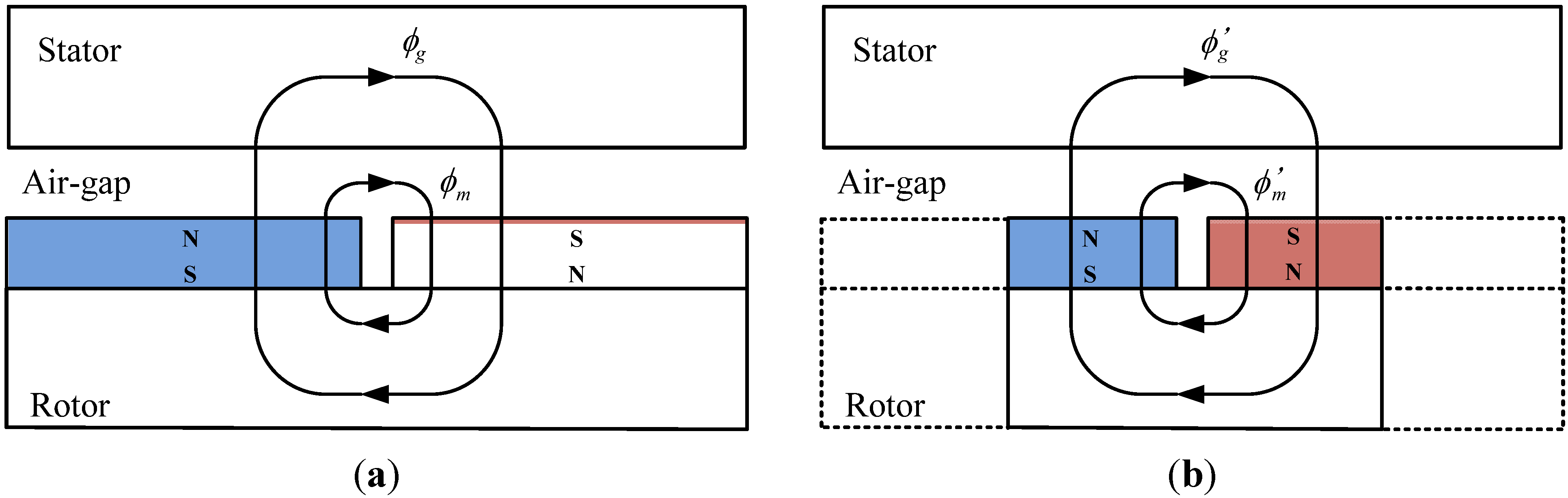
2. Derivation of Cogging Torque
3. Principle of HMPP Analysis for Evaluating Cogging Torque
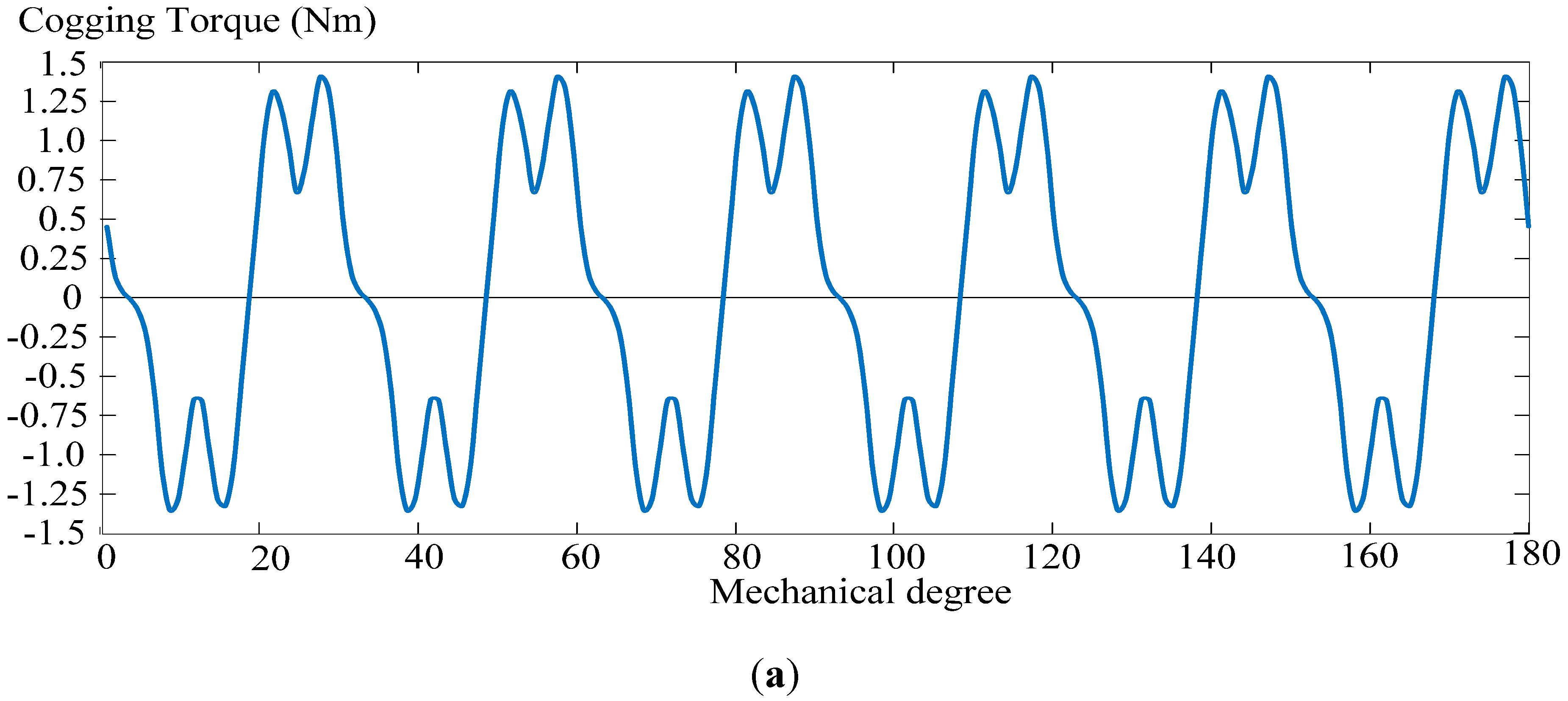
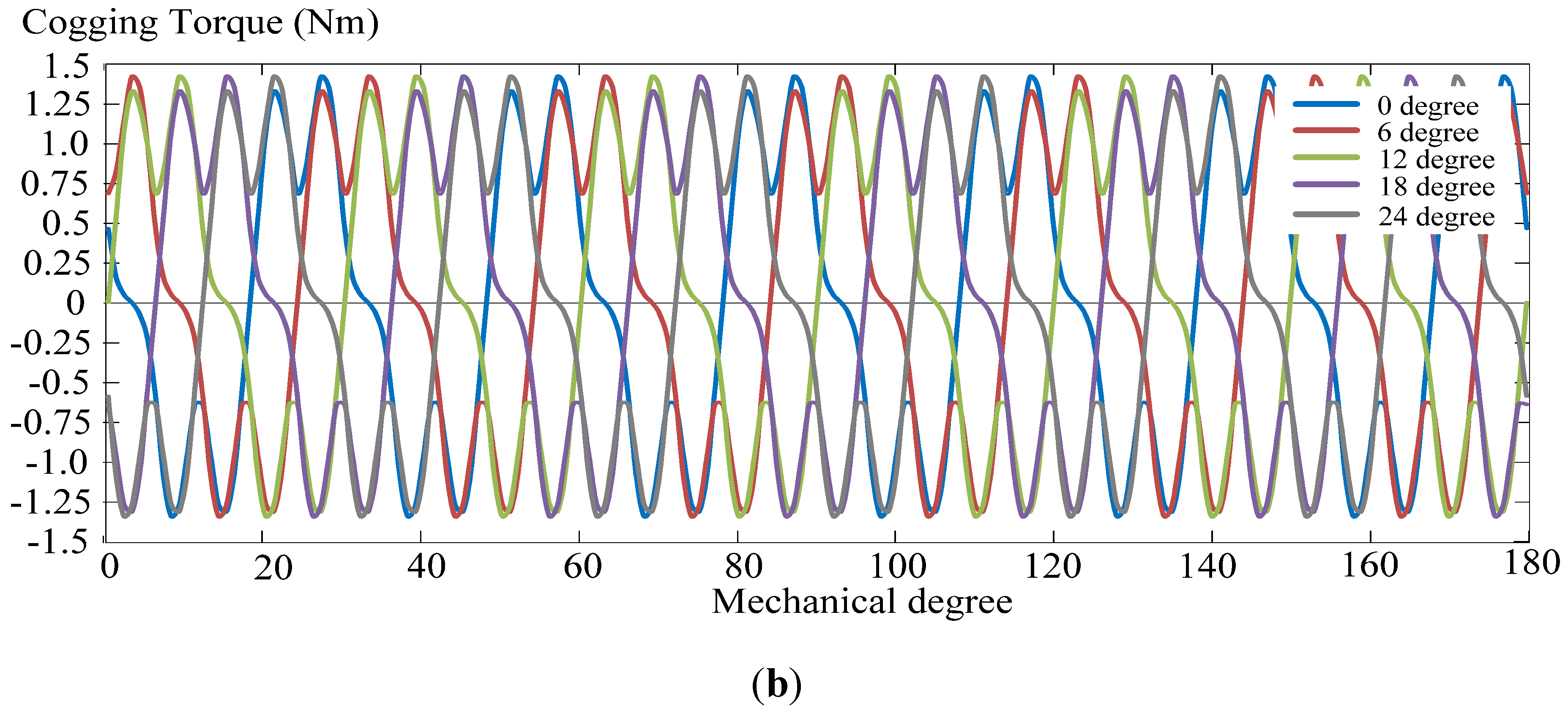
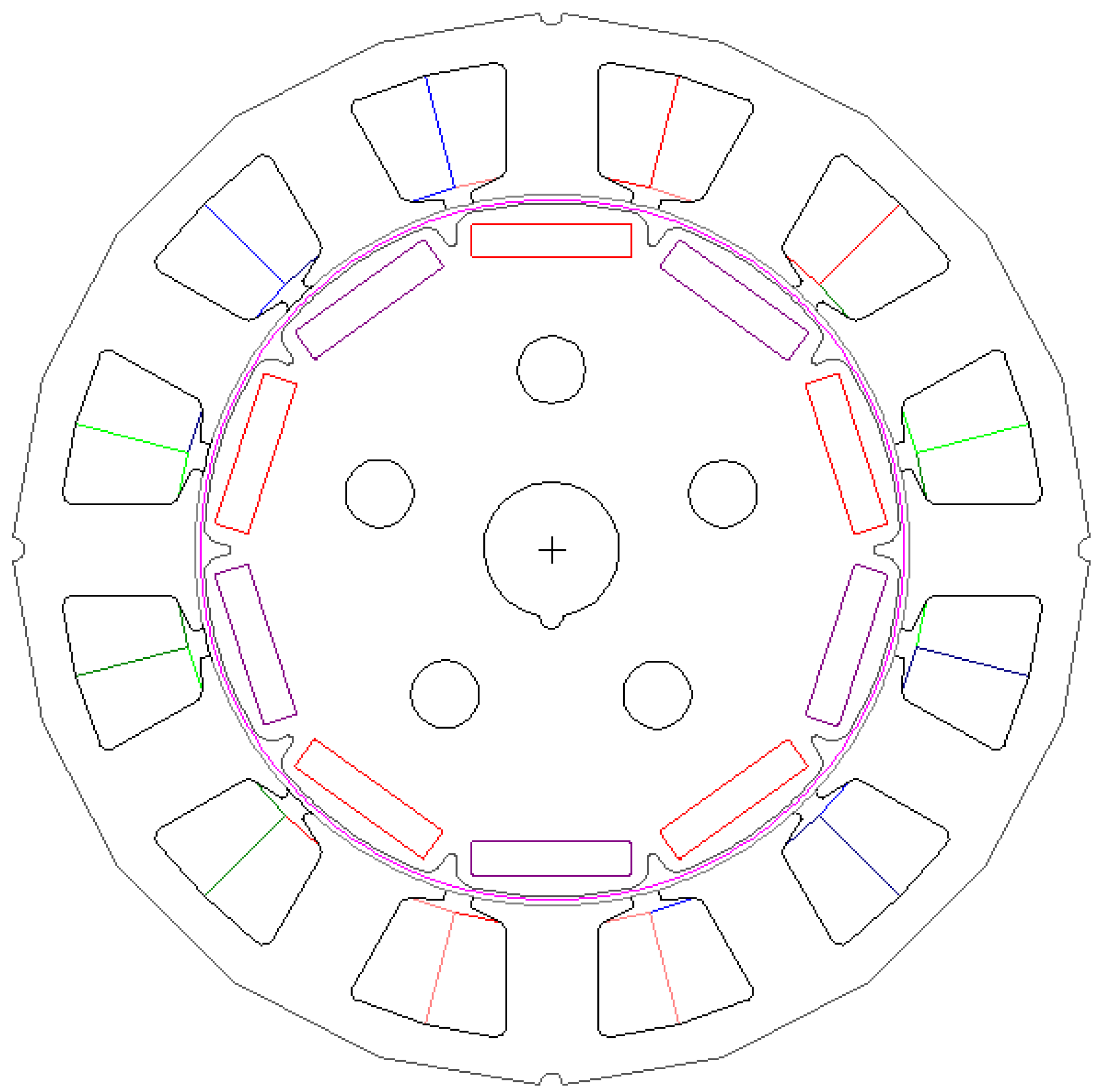
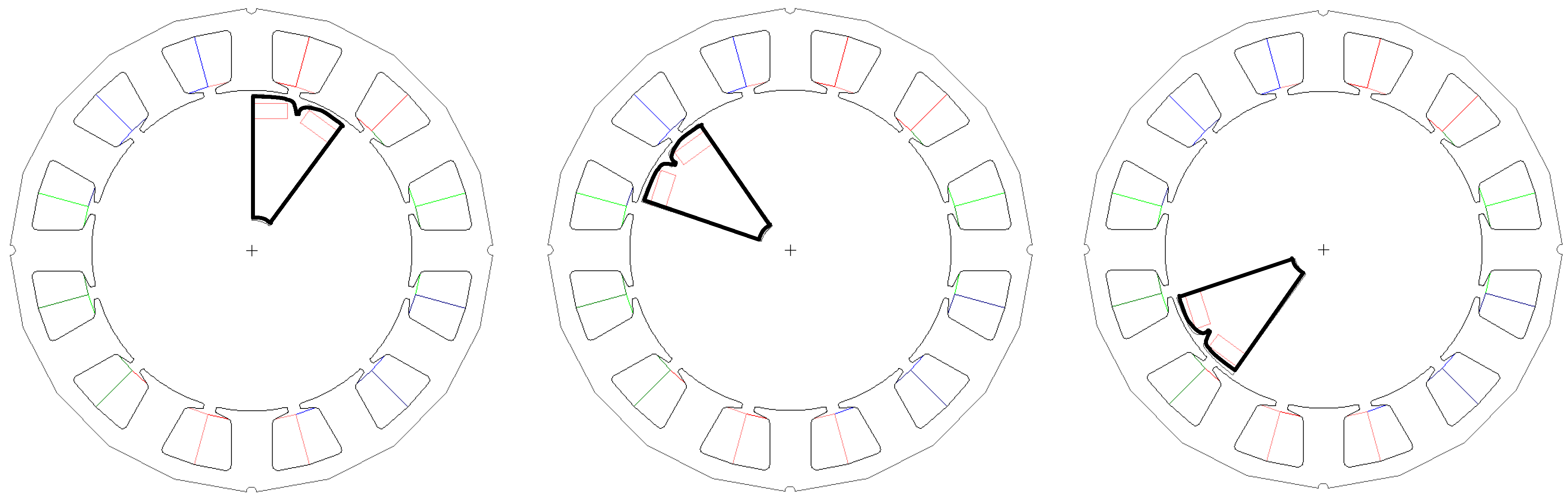
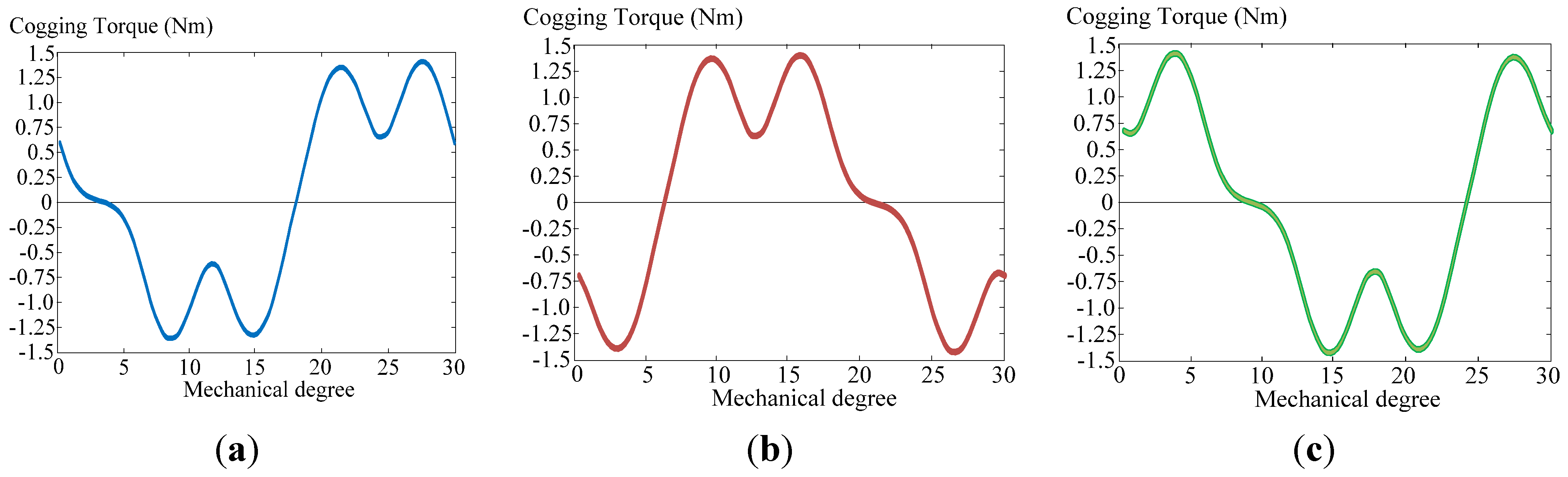
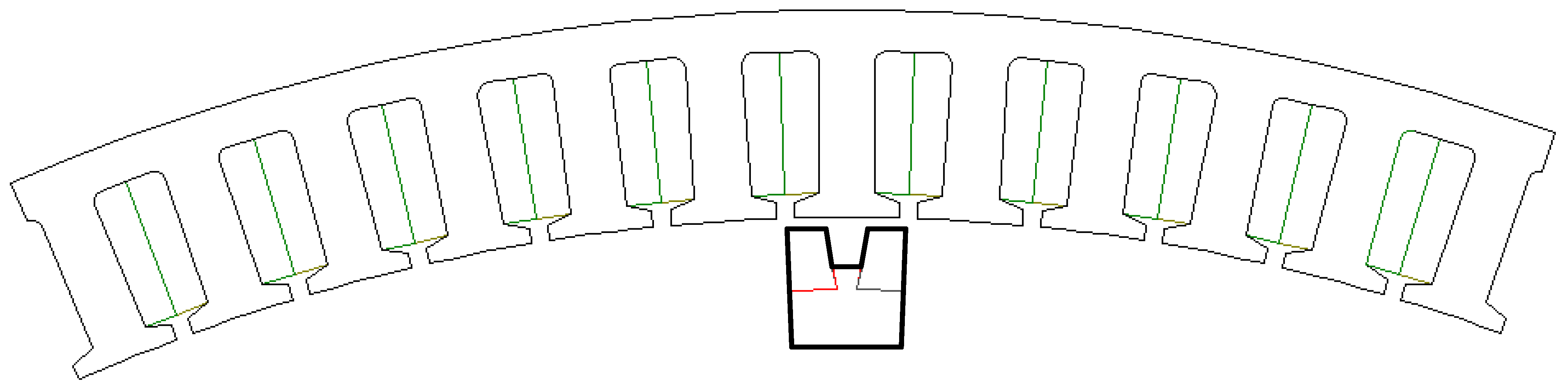
3.1. Definition of HMPP and Reproduction of the Cogging Torque

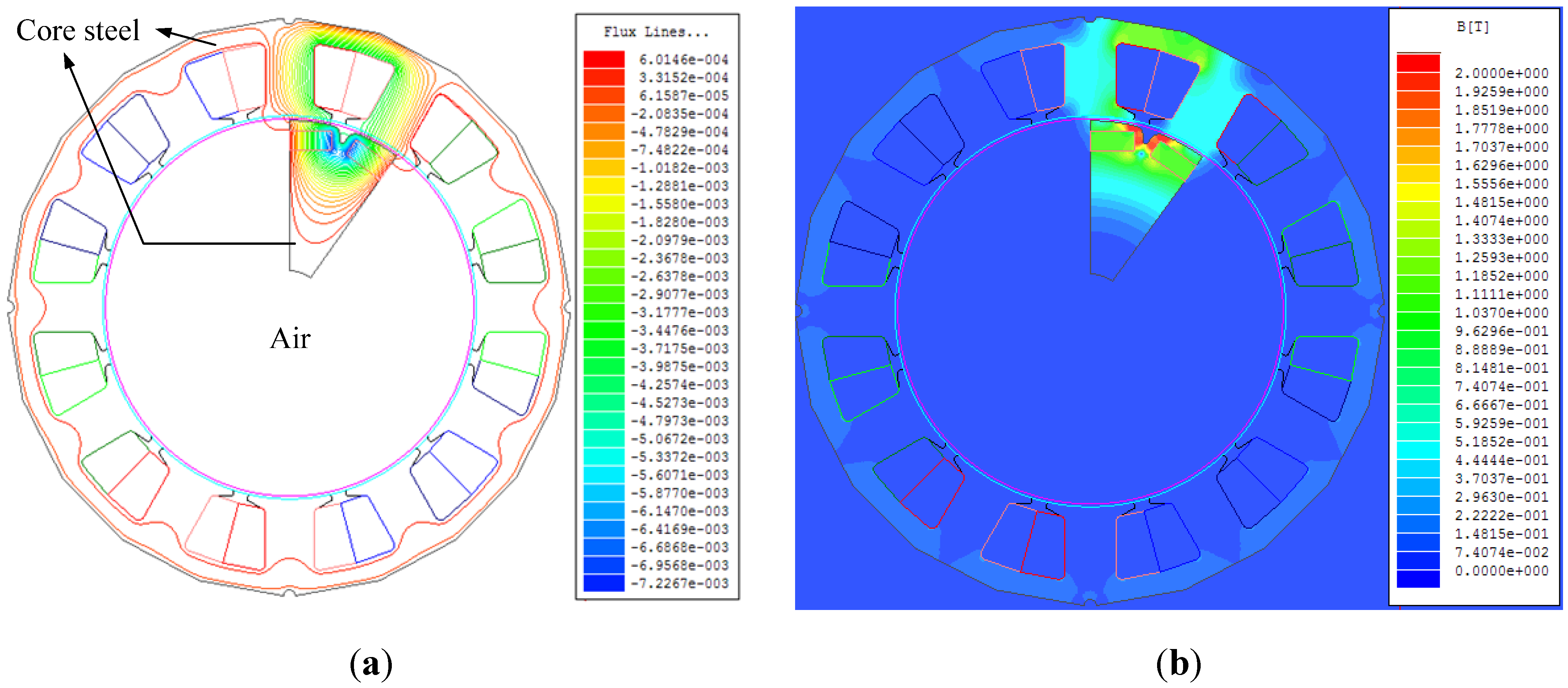
3.2. Finite Element Method of HMPP in Cogging Torque Analysis


| 1 | 2 | 3 | 4 | 5 | 6 | 7 | 8 | 9 | 10 | ||
|---|---|---|---|---|---|---|---|---|---|---|---|
| Accumulated angle | |||||||||||
| Original mechanical degree () | 0 | 6 | 12 | 18 | 24 | 30 | 36 | 42 | 48 | 54 | |
| Partitioned mechanical degree () | 0 | 6 | 12 | 18 | 24 | 0 | 6 | 12 | 18 | 24 | |
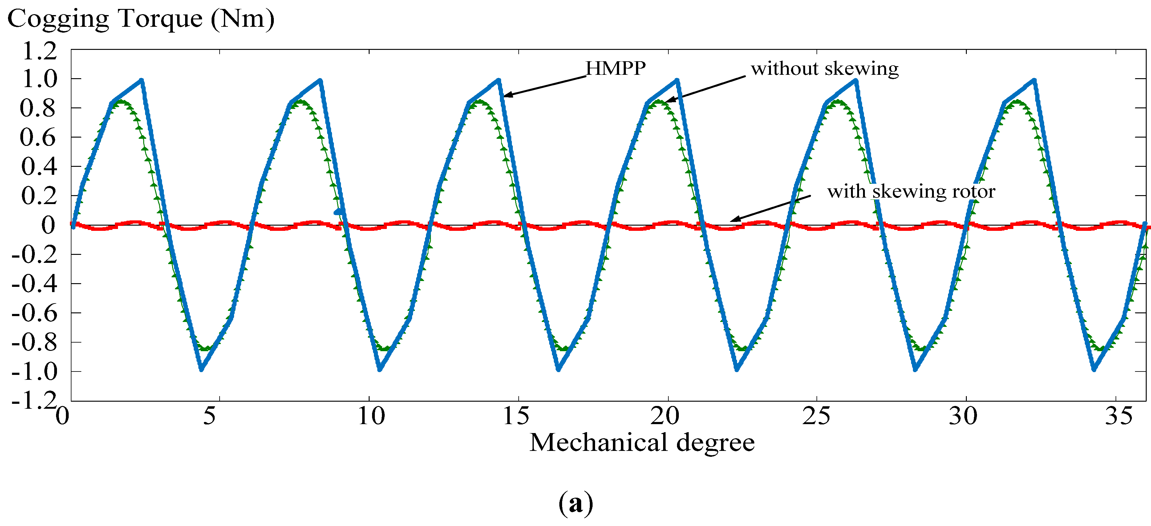

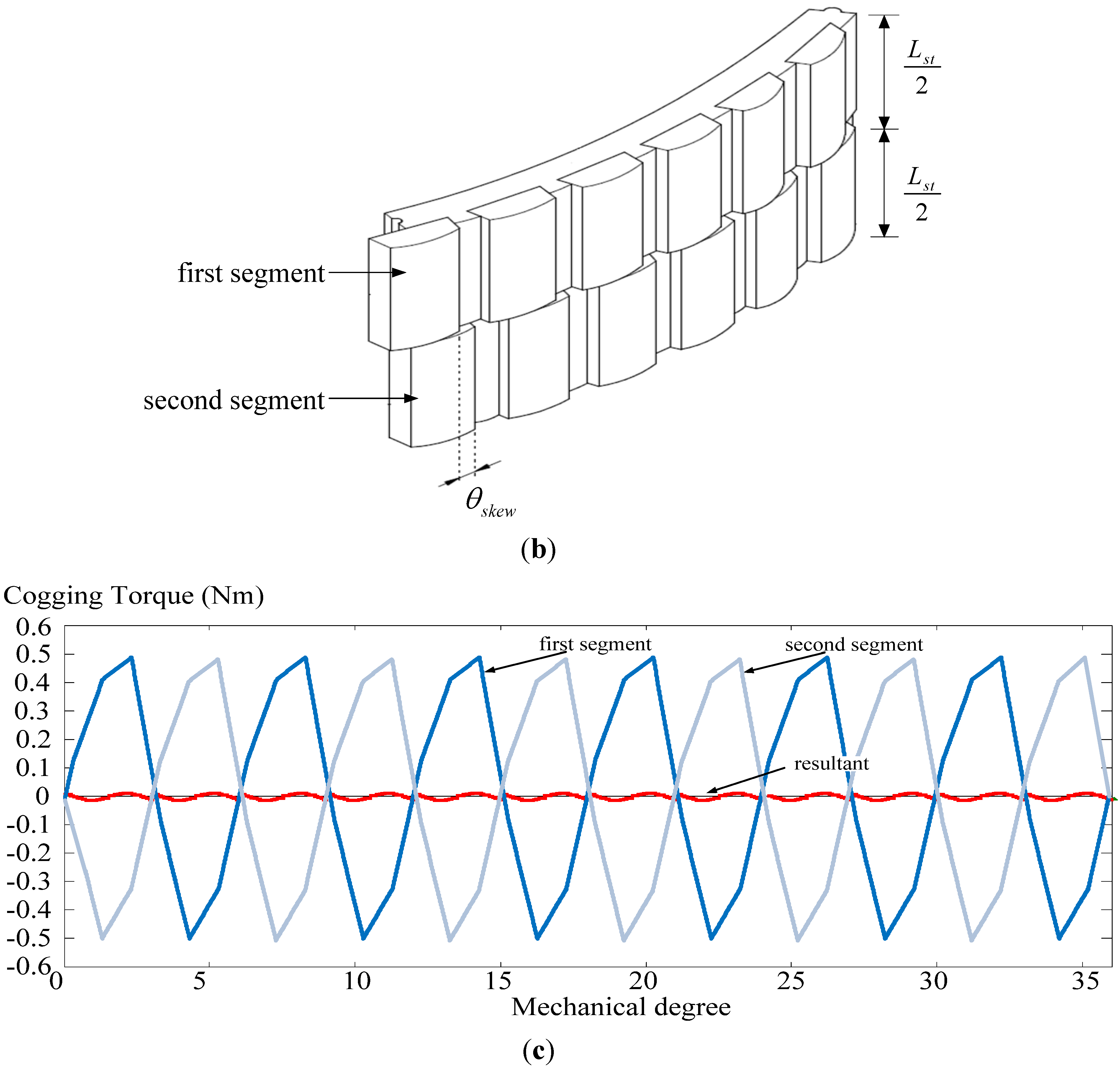
4. Application of the Novel HMPP Method to Analysis of Wind Generator
| Number of phase | 3 |
| Number of slots | 96 |
| Number of poles | 100 |
| Rated speed (rpm) | 90 |
| Rated output power (W) | 3000 |
| Rated torque (Nm) | 318.17 |
| Back-emf (V) | 215.4 |
| Winding turns per slot (turns) | 18 |
| Winding conductor diameter (mm) | 1.0 |
| Stator diameter inner/outer (mm) | 720/800 |
| Rotor diameter inner/outer (mm) | 670/716 |
| Air-gap length (mm) | 2 |
| Stack length (mm) | 60 |
| Core material/Permanent magnet | 50CS400/NdFeB35 |

| 1 | 2 | 3 | 4 | 5 | 6 | 7 | 8 | 9 | 10 | 11 | 12 | ||
| Mechanical degrees () | 0 | 0.15 | 0.3 | 0.45 | 0.6 | 0.75 | 0.9 | 1.05 | 1.2 | 1.35 | 1.5 | 1.65 | |
| 13 | 14 | 15 | 16 | 17 | 18 | 19 | 20 | 21 | 22 | 23 | 24 | ||
| Mechanical degrees () | 1.8 | 1.95 | 2.1 | 2.25 | 2.4 | 2.55 | 2.7 | 2.85 | 3 | 3.15 | 3.3 | 3.45 | |
| 25… | |||||||||||||
| Mechanical degrees () | 3.6 | 3.75→0, 3.9→0.15, 4.05→0.3, 4.2→0.45… …and so on. | |||||||||||
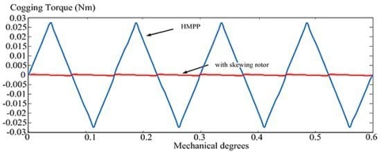
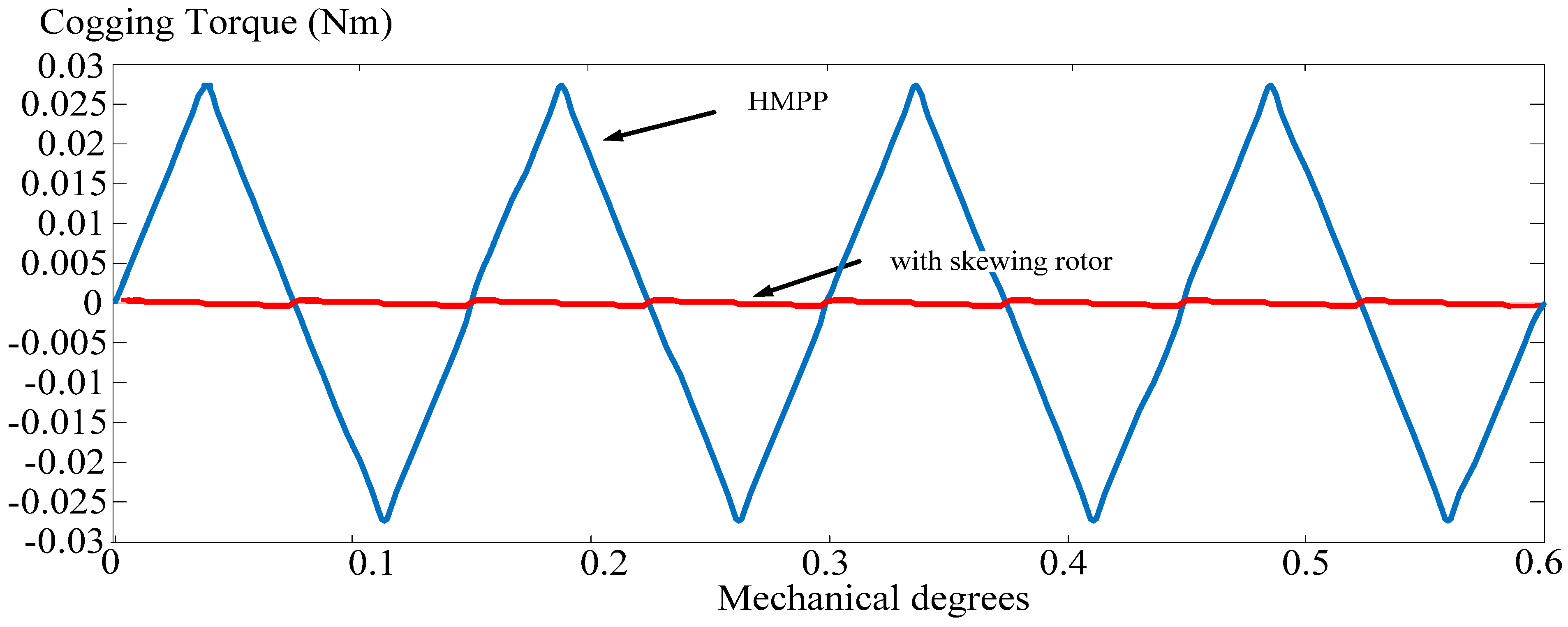
| HMPP | |
|---|---|
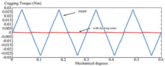
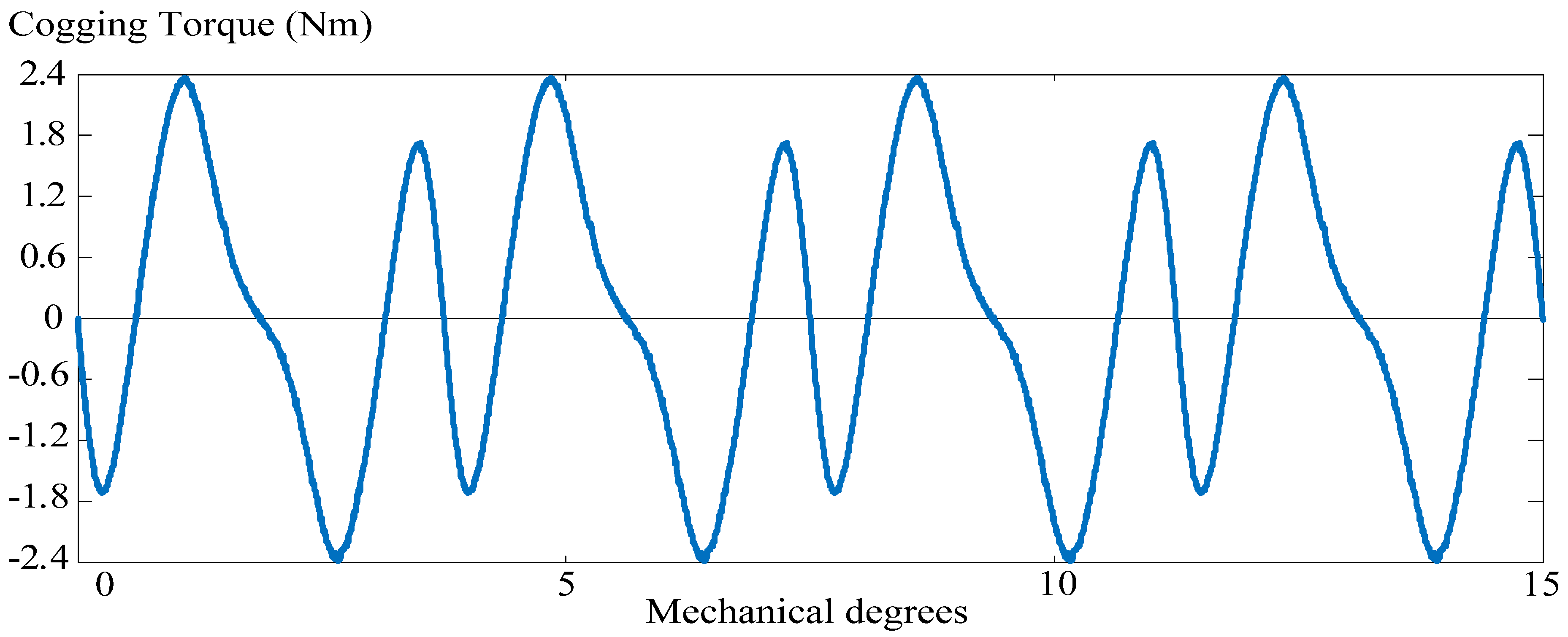
| Cogging torque analysis | 0.054 Nm (pp) |
| Total process time | 60 min. |
| Cogging torque with skewing rotor | 0.0007 Nm (pp) |
| Cogging torque reduction | 98.7% |
5. Conclusions
References
- Kang, G.H.; Son, Y.D.; Kim, G.T.; Hur, J. A novel cogging torque reduction method for interior-type permanent-magnet motor. IEEE Trans. Ind. Appl. 2009, 45, 161–167. [Google Scholar] [CrossRef]
- Güemes, J.A.; Iraolagoitia, A.M.; del Hoyo, J.I.; Fernández, P. Torque analysis in permanent-magnet synchronous motors: A comparative study. IEEE Trans. Energy Convers. 2011, 26, 55–63. [Google Scholar] [CrossRef]
- Islam, R.; Husain, I.; Fardoun, A.; McLaughlin, K. Permanent-magnet synchronous motor magnet designs with skewing for torque ripple and cogging torque reduction. IEEE Trans. Ind. Appl. 2009, 45, 152–160. [Google Scholar] [CrossRef]
- EL-Refaie, A.M. Fractional-slot concentrated-windings synchronous permanent magnet machines: Opportunities and challenges. IEEE Trans. Ind. Electron. 2010, 57, 107–121. [Google Scholar] [CrossRef]
- Popescu, M.; Cistelecan, M.V.; Melcescu, L.; Covrig, M. Low Speed Directly Driven Permanent Magnet Synchronous Generators for Wind Energy Applications. In Proceedings of the International Conference on Clean Electrical Power, Capril, Italy, 21–23 May 2007; pp. 784–788.
- Wang, Y.; Jin, M.J.; Fei, W.Z.; Shen, J.X. Cogging torque reduction in permanent magnet flux-switching machines by rotor teeth axial pairing. IET Electric Power Appl. 2010, 4, 500–506. [Google Scholar] [CrossRef]
- Wang, D.; Wang, X.; Qiao, D.; Pei, Y.; Jung, S.-Y. Reducing cogging torque in surface-mounted permanent-magnet motors by nonuniformly distributed teeth method. IEEE Trans. Magn. 2011, 47, 2231–2239. [Google Scholar] [CrossRef]
- Hanselman, D. Brushless Permanent Magnet Motor Design; Magna Physics Pub: Orono, ME, USA, 2003. [Google Scholar]
- Islam, M.S.; Islam, R.; Sebastian, T. Experimental verification of design techniques of permanent-magnet synchronous motors for low-torque-ripple applications. IEEE Trans. Ind. Appl. 2011, 47, 88–95. [Google Scholar] [CrossRef]
- Ho, S.L.; Chen, N.; Fu, W.N. An optimal design method for the minimization of cogging torques of a permanent magnet motor using FEM and genetic algorithm. IEEE Trans. Appl. Supercond. 2010, 20, 861–864. [Google Scholar] [CrossRef]
- Hendershot, J.R.; Miller, T.J.E. Design of Brushless Permanent Magnet Motors; Oxford University Press: New York, NY, USA, 1994. [Google Scholar]
- Bianchi, N.; Bolognani, S. Design techniques for reducing the cogging torque in surface-mounted PM motors. IEEE Trans. Ind. Appl. 2002, 38, 1259–1265. [Google Scholar] [CrossRef]
- Dai, M.; Keyhani, A.; Sebastian, T. Torque ripple analysis of a PM brushless DC motor using finite element method. IEEE Trans. Energy Convers. 2004, 19, 40–45. [Google Scholar] [CrossRef]
- Zhu, Z.Q.; Howe, D. Influence of design parameters on cogging torque in permanent magnet machines. IEEE Trans. Energy Convers. 2000, 15, 407–412. [Google Scholar] [CrossRef]
- Sooriyakumar, G.; Perryman, R.; Dodds, S.J. Cogging Analysis for Fractional Slot/Pole Permanent Magnet Synchronous Motors. In Proceedings of the 42nd International Universities Power Engineering Conference, Brighton, UK, 4–6 September 2007; pp. 188–191.
- Wang, D.; Wang, X.; Yang, Y.; Zhang, R. Optimization of magnetic pole shifting to reduce cogging torque in solid-rotor permanent-magnet synchronous motors. IEEE Trans. Magn. 2010, 46, 1228–1234. [Google Scholar] [CrossRef]
- Ohnishi, T.; Takahashi, N. Optimal design of efficient IPM motor using finite element method. IEEE Trans. Magn. 2000, 36, 3537–3539. [Google Scholar] [CrossRef] [Green Version]
- Pern, J.-F.; Yeh, S.-N. Calculating the current distribution in power transformer windings using finite element analysis with circuit constraints. IEE Proc. Sci. Meas. Technol. 1995, 142, 231–236. [Google Scholar] [CrossRef]
- Chen, C.-Y.; Yeh, S.-N. An improved finite element method for electromagnetic field analysis. J. Chin. Instit. Electr. Eng. 1996, 3, 245–251. [Google Scholar]
- Chen, C.-Y.; Yeh, S.-N. An improved finite element method for induction motor analysis. J. Chin. Inst. Electr. Eng. 1996, 3, 27–36. [Google Scholar]
- Lefévre, Y.; Fontchastagner, J.; Messine, F. Building a CAD system for educational purpose based only on a mesh tool and a finite elements solver. IEEE Trans. Magn. 2006, 42, 1483–1486. [Google Scholar] [CrossRef]
- Kim, K.-C.; Lee, J.; Kim, H.-J.; Koo, D.-H. Multiobjective optimal design for interior permanent magnet synchronous motor. IEEE Trans. Magn. 2009, 45, 1780–1783. [Google Scholar] [CrossRef]
- Andriollo, M.; de Bortoli, M.; Martinelli, G.; Morini, A.; Tortella, A. Design improvement of a single-phase brushless permanent magnet motor for small fan appliances. IEEE Trans. Ind. Electron. 2010, 57, 88–95. [Google Scholar] [CrossRef]
- Van der Giet, M.; Lange, E.; Corrêa, D.A.P.; Chabu, I.E.; Nabeta, S.I.; Hameyer, K. Acoustic simulation of a special switched reluctance drive by means of field–circuit coupling and multiphysics simulation. IEEE Trans. Ind. Electron. 2010, 57, 2946–2953. [Google Scholar]
- Cho, H.-W.; Ko, K.-J.; Choi, J.-Y.; Shin, H.-J.; Jang, S.-M. Rotor natural frequency in high-speed permanent-magnet synchronous motor for turbo-compressor application. IEEE Trans. Magn. 2011, 47, 4258–4261. [Google Scholar] [CrossRef]
- Li, G.J.; Ojeda, J.; Hoang, E.; Gabsi, M. Thermal-electromagnetic analysis of a fault-tolerant dual-star flux-switching permanent magnet motor for critical applications. IET Electric Power Appl. 2011, 5, 503–513. [Google Scholar] [CrossRef]
- Borghi, C.A.; Casadei, D.; Cristofolini, A.; Fabbri, M.; Serra, G. Minimizing torque ripple in permanent magnet synchronous motors with polymer-bonded magnets. IEEE Trans. Magn. 2002, 38, 1371–1377. [Google Scholar] [CrossRef]
- Chen, H.-S.; Dorrell, D.G.; Tsai, M.-C. Design and operation of interior permanent-magnet motors with two axial segments and high rotor saliency. IEEE Trans. Magn. 2010, 46, 3664–3675. [Google Scholar] [CrossRef]
- Jiabin, W.; Yabin, P. Research of Six-Pole Permanent Magnet Submersible Motor Design. In Proceedings of the 6th International Forum on Strategic Technology, Harbin, China, 22–24 August 2011; pp. 545–548.
© 2011 by the authors; licensee MDPI, Basel, Switzerland. This article is an open access article distributed under the terms and conditions of the Creative Commons Attribution license (http://creativecommons.org/licenses/by/3.0/).
Share and Cite
Hsiao, C.-Y.; Yeh, S.-N.; Hwang, J.-C. A Novel Cogging Torque Simulation Method for Permanent-Magnet Synchronous Machines. Energies 2011, 4, 2166-2179. https://doi.org/10.3390/en4122166
Hsiao C-Y, Yeh S-N, Hwang J-C. A Novel Cogging Torque Simulation Method for Permanent-Magnet Synchronous Machines. Energies. 2011; 4(12):2166-2179. https://doi.org/10.3390/en4122166
Chicago/Turabian StyleHsiao, Chun-Yu, Sheng-Nian Yeh, and Jonq-Chin Hwang. 2011. "A Novel Cogging Torque Simulation Method for Permanent-Magnet Synchronous Machines" Energies 4, no. 12: 2166-2179. https://doi.org/10.3390/en4122166