Article

A Proposal for CO2 Abatement in Urban Areas: The UDR1–Lethe© Turbo-Hybrid Vehicle

Department of Mechanical and Aerospace Engineering, University of Roma 1 “La Sapienza”, Italy
*
Author to whom correspondence should be addressed.
Energies 2011, 4(3), 368-388; https://doi.org/10.3390/en4030368
Submission received: 6 December 2010 / Revised: 1 February 2011 / Accepted: 23 February 2011 / Published: 1 March 2011
(This article belongs to the Special Issue Hybrid Vehicles)

Abstract

:
For years the interest of the University of Roma 1 (UDR1) research group has been focused on the development of a Hybrid Series vehicle (called Lethe©), different from standard ones, thanks to the use of a Gas Turbine (GT) set as a thermal engine. The reason for this choice resides in the opportunity to reduce weight and dimensions, in comparison to a traditional Internal Combustion Engine. It’s currently not possible to use the GT engine set directly for the vehicle traction, so the UDR1 HS configuration only shows the GT set connected with the electric generator. The result is that the traction is purely electric. The resulting engine configuration is commonly described as a Hybrid Series Plug In. Several previous studies have been carried out, and this research has allowed us to define the correct ratio (Degree of Hybridization) between the installed power of the battery pack and that of the GT electric generator which simultaneously guarantee the main life for the battery package and the capacity of the vehicle to complete a common mission without lack of energy or stopping. This article reports the final step of the research: once all data has been calculated, how to “hybridize” a commercial city car, passenger sedan or any other vehicle.

1. Introduction

In the worldwide context of fossil fuel reduction and limitation of CO2 emissions, the sector that has enjoyed the lowest number of initiatives is the transport system, in spite of the fact that it is one of the largest sources of petroleum consumption and the greatest source of smog pollution in our towns and cities. The entire sector linked to individual mobility has been singled out for many years now as one of the greatest culprits of pollutant emissions. In spite of this, the field of transportation has had the lowest tangible results in achieving the goal of limiting consumption. In the last few decades, in response to the increasingly stricter laws issued by law-making bodies on the matter of limiting pollutant gas emissions, we have witnessed a continuous increase of the size of engines and the weight of vehicles placed on the market by the large car-manufacturing companies. From a technological point of view, the traditional internal combustion engine (ICE) has not undergone any innovation in recent years that could have a concrete, tangible improvement on motor efficiency and a consequent limitation of consumption, and, no great innovation is foreseen in the next few years either. We acknowledge the dream of seeing all circulating traffic replaced by electrical vehicles will not become reality in the mid-term, due to the problems linked to the inadequate accumulation systems that could not satisfy the need for autonomy and refuelling performance required by the market, so it is natural to investigate if an intermediate technology already exists, that would allow some partial advantages such as fuel consumption and pollutant gas emission reductions. The Hybrid Series Plug-In vehicle is clearly the answer to this question. It is technologically a traditional vehicle, and is thus a break with the past for car-manufacturing companies who would only have to adapt their current production lines with insubstantial changes without the need to divest themselves of it. Finally, it is an electrical vehicle and could allow large-scale development of this type of technology, instead of being relegated to a niche market.

2. The Lethe© Plug in-Hybrid Series Vehicle

A hybrid vehicle is a wheeled vehicle in which motion is supplied by two different types of motor, a traditional thermal one and an electrical one. A hybrid series vehicle is one in which the motion is supplied exclusively by the electrical motor and the thermal motor has the dual function of being the charger for the accumulators when the vehicle is at a standstill and being a range extender when the vehicle is moving. Plug in indicates an option of being able to charge the accumulators using not only the installed thermal motor, but also using a connection to the electrical grid when the vehicle is at a standstill. The advantages of this configuration are as follows:
-
The opportunity to design the thermal motor to be used at a nominal point, with an immediate increase in efficiency and a reduction in installed power. Both have positive effects on consumption reduction and limiting emissions.
-
The possibility offered by an electrical vehicle of using Kinetic Energy Recovery System (KERS) devices to recover energy. In this case too, there is a reduction in consumption and polluting emissions.
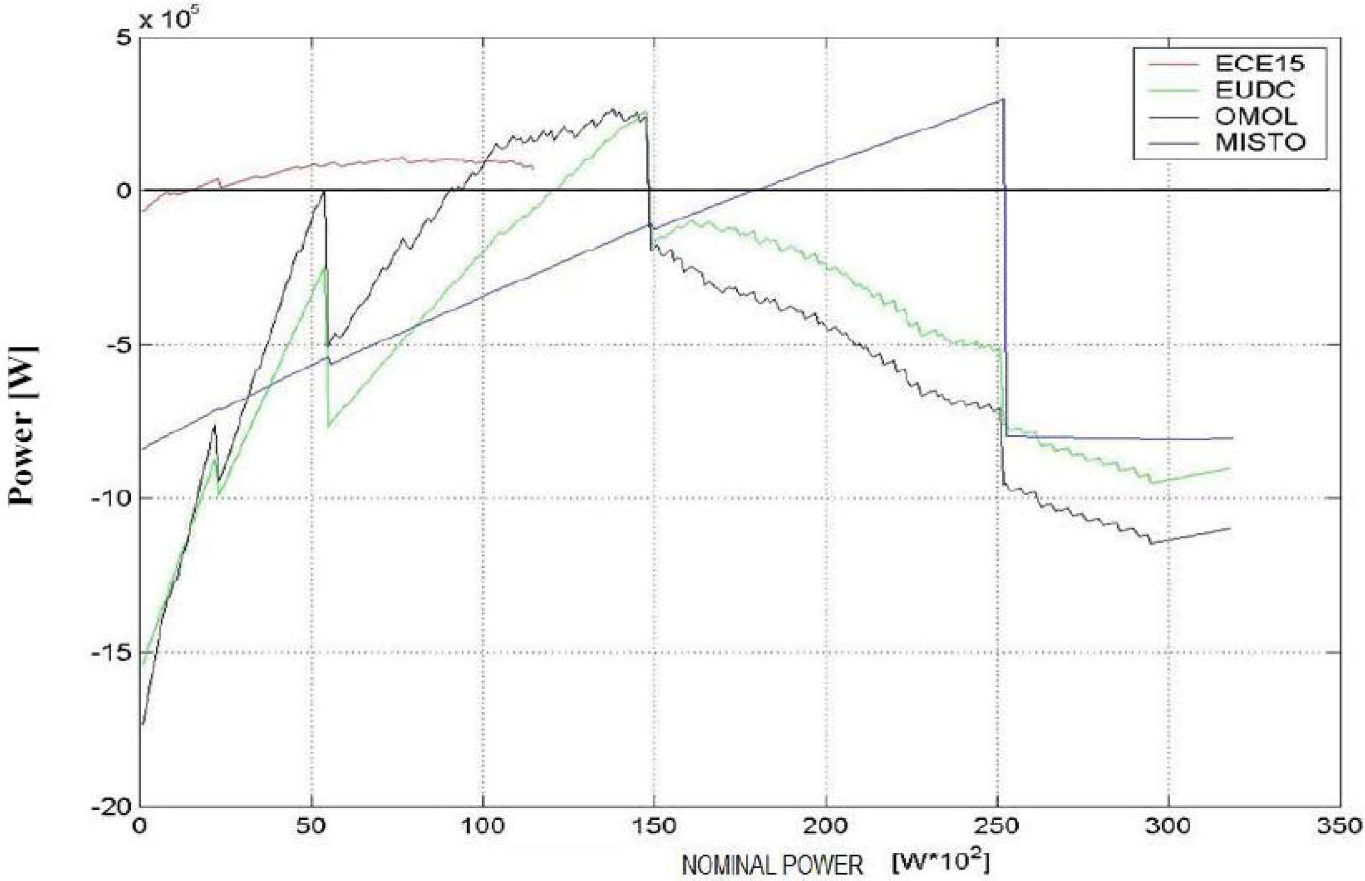
The advantages in terms of consumption reduction would be immediate and easy to achieve, especially for all those vehicles that are typically used in frequent stop & go conditions, as are all vehicles operating in traffic. As for the vehicle system, there is no formal difference between a traditional means and a hybrid series one. The main elements are the thermal motor, electrical motor and accumulators, all of which are present in a commercial car. Figure 1 shows the balance between energy consumed by a common car during standard routes and the energy produced by a thermal motor during a trip in a hybrid series.
The possible nominal power range of the thermal motor so that all or almost energy is generated during the entire trip, as seen in the graph, ranges from 10 kWp to 15 kWp, i.e., about one sixth or less compared to vehicles currently available on the market. The changes (purely to systems) concern interconnections between these three elements and the rest of the car. The electrical motor is connected to the gear in place of the thermal motor, while the latter is only connected to the electrical generator and the battery package will be connected directly to the electrical motor to power it. The overall elements’ dimensions will clearly change compared to an equivalent traditional vehicle. The electrical motor would have a much larger volume, the thermal motor would be smaller and this reduction in size would allow to house higher-capacity accumulators.
Figure 1. Energy balance as function of installed GT power and track [1].
Energies 04 00368 g001

3. How to Hybridize a Vehicle

In the vehicle hybridisation process, once the initial calculations have been completed, as indicated in previous works [1,2,3,4,5], each component to make any vehicle a Low Emission Turbo Hybrid Electric Vehicle (Lethe©) vehicle is then studied separately.

3.1. Electric Motor

The size and weight of the electrical motor are established in relation to the model A1H 207 C44 G 000 [6], which was chosen after a thorough market research (Figure 2). Its technical specifications are provided in Table 1 below.
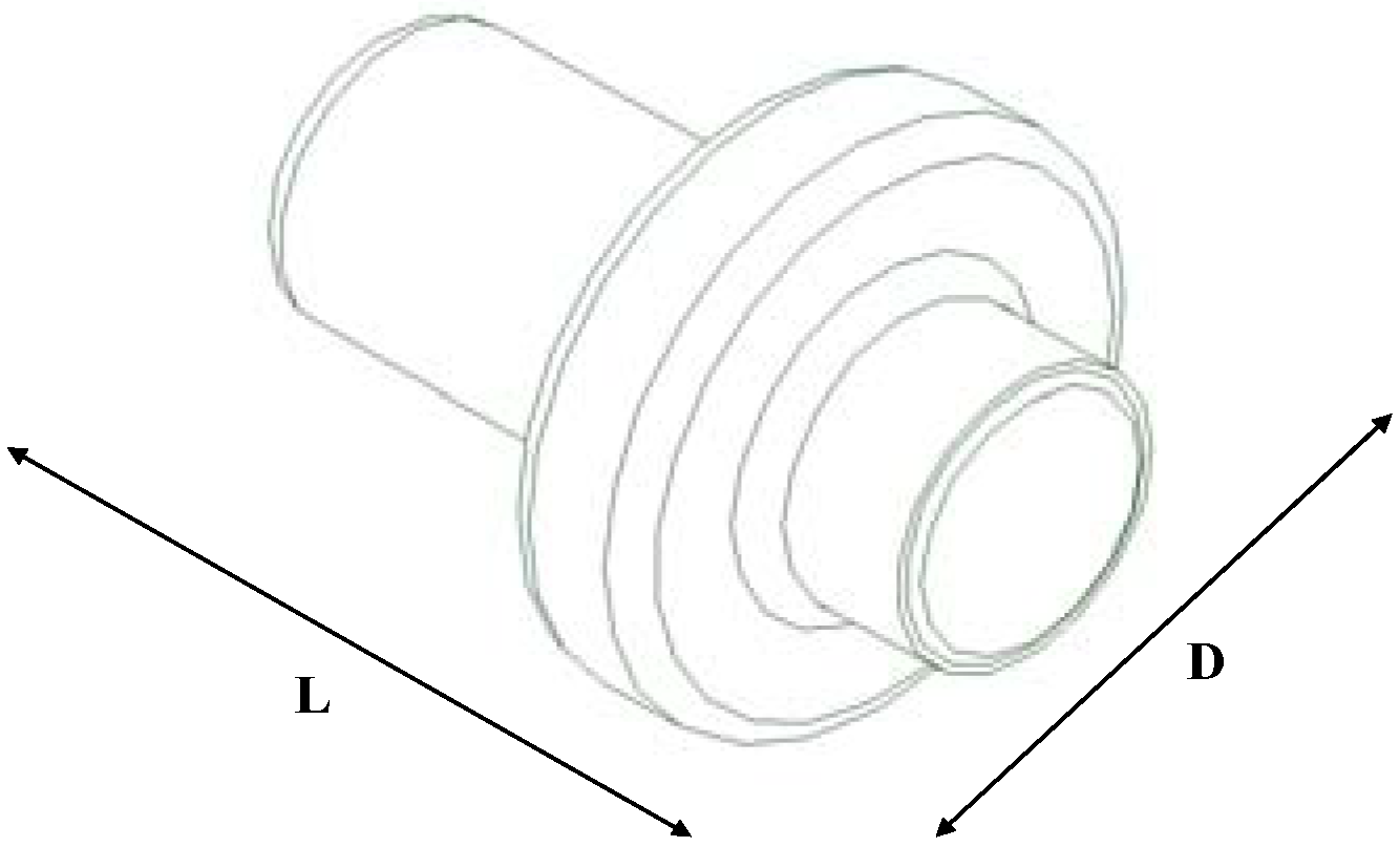
Figure 2. Asynchronous motor da 30 kW; L = 315 mm, D = 264 mm.
Energies 04 00368 g002

3.2. Inverter

The size and weight of the electronic converter (Figure 3) correspond to those of the model I1H 130 HG 000 [6], whose technical specifications are provided in Table 2.

3.3. Battery Package

The adopted battery package (Figure 4) is a Pb-acid one (due to availability and low cost) produced by GENESIS, Hawker Energy [6], model G12V42Ah10EP/V; technical specifications are reported in Table 3.
Table 1. Electric Motor.
Electric Motor CharacteristicsAsynchronous
Nr. Phases3
Nr. Poles4
Nominal torque (Nm)130
Max Torque at 2300 rpm (Nm)260
Nom. Max. speed (rpm)10,000
Maximum speed (rpm)9000
Power S1 (kW)30
Peak Power S2 (kW)60
Insulation categoryH
Protection ratingIP 56
Dimensions (mm)Ø264 × 315
Weight (kg)80
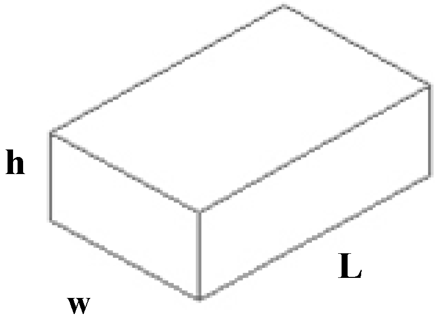
Figure 3. Inverter; L = 410 mm, w = 340 mm, h = 138 mm.
Energies 04 00368 g003
Table 2. Inverter.
Table 2. Inverter.
Type I1H 130 HG 000
Voltage (V)190/380
Max Input Current (A)280 A
Max AC current (A)400 A
ModulationPWM
Max frequency (Hz)400
Switching frequency (kHz)4
Type of Controlmicroprocessor
Operational tempreature (°C)−20 to +65
Dimensions (mm)410 × 340 × 138
Weight (kg)15
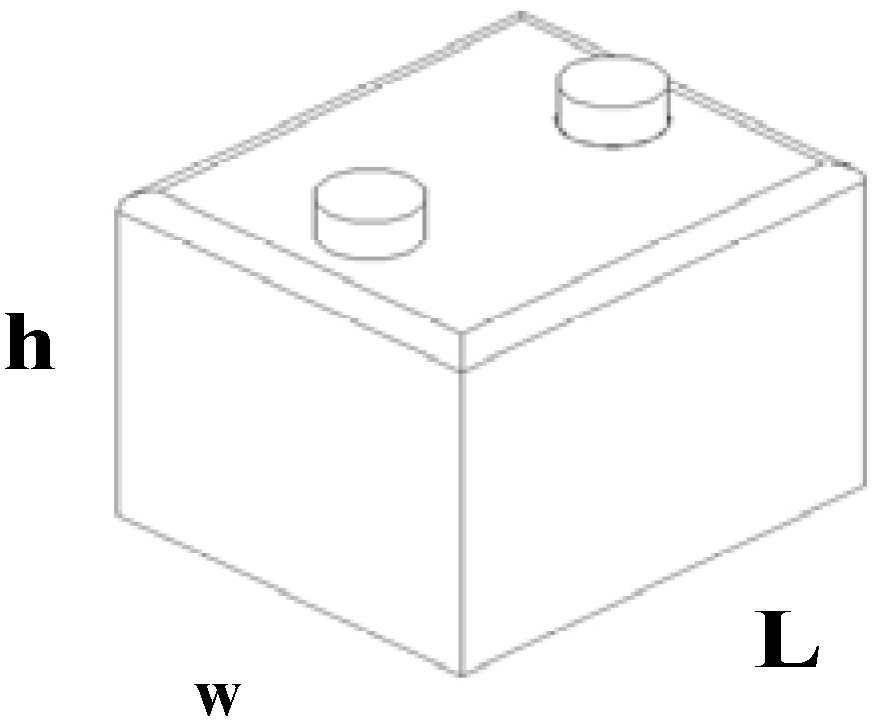
Figure 4. GENESIS® battery module; L = 200 mm, w = 170 mm, h = 170 mm.
Energies 04 00368 g004
Table 3. Battery Module.
Genesis® Battery Module
Dimensions (mm)200 × 170 × 170
Weight (kg)15

3.4. Gas Turbine Device

The design of the GT units was not a subject of this study, therefore the sizes and weights of the two 10 and 15 kW units were not expressly calculated. However, in this study, reference is made to the size of the 30 kW Capstone turbo-generator C30HEV [7], which is certainly larger than the ones chosen for the two LETHE© vehicle configurations, therefore the study of the sizes on a frame is carried out in relation to an excess size. Indeed, we presumed that the temperature (1300 K) and speed (100,000 rpm), for the two GT devices (10 and 15 kW) were the same as the C30HEV, therefore with an initial approximation, the sizes should be scaled respectively by a factor of 1/2 and 1/3. With the shape and size of the C30HEV [8] established, the GT group was rebuilt as shown in Figure 5. The weight of the part was also evaluated to excess, having considered to be a single steel cylinder (δsteel = 7.87 kg/dm3). Table 4 reports the technical data.
Figure 5. Gas Turbo-generator; L = 465 mm, D = 200 mm.
Energies 04 00368 g005
Table 4. GT Data.
Table 4. GT Data.
GT Device
Dimensions (mm)Ø200 × 465
Weight (kg)23

3.5. Regenerator Device

Similarly to the turbo-generator, the size of the regenerator was evaluated by considering the volume of the C30HEV regenerator (maintaining the same side section), while the weight was calculated by presuming that the part was made in aluminium (δAl = 2700 kg/m3) and the internal volume was the half of the total volume. The connections between turbo-gas and regenerator were not considered. Technical characteristics are given through Table 5 and Figure 6.
Figure 6. Regenerator; L = 340 mm, w = 215 mm, h = 120 mm.
Energies 04 00368 g006
Table 5. Regenerator device.
Regenerator
Dimensions (mm)340 × 215 × 120
Weight (kg)12

3.6. Fuel Tank

The gas tank is the model 991102078, chosen from among the several models offered by Autogas Italia Srl [9]. Technical characteristics are given in Figure 7 and Table 6.
Figure 7. Fuel tank; L = 880 mm, D = 270 mm.
Energies 04 00368 g007
Table 6. Fuel Tank.
Table 6. Fuel Tank.
Fuel Tank Characteristics
Volume (L)45
Pressure (kPa (30 kg/cm2))3000
Working pressure (kPa (30 kg/cm2)Max 2000
Dimensions (mm)Ø270 × 880
Weight (kg)37

3.7. Fly Wheel

Although for the two LETHE© [4] vehicle configurations chosen, we considered to install it in view of an operational mode of the vehicle that would be different from that of the simulated one (sharp braking, downward slopes). As it is an extra part, however, its sizing was a compromise between storable energy and volume. Once the amount of energy that the flywheel had to absorb (20 kJ) and the maximum rotation speed had been set, the weight and disk radius were also formulated, using classic formulae. A rotation of 20,000 rpm was presumed, as it allows flywheel size to remain relatively compact and does not require technologically advanced designing for the electrical motor. It is presumed that:
Max Ecin = 20 kJ;
Max speed = 20,000 rpm;
The flywheel consists of a steel disk (δsteel = 7.87 kg/dm3) k = 1/2 therefore from:
Ecin = ½ Iω2
and
I = kMR2
it is found that I = 9.13·× 10−3 kg m2 and by setting the flywheel radius R = 0.08 m finally M = 3 kg and s = 2 cm (s: disk thickness) are obtained.
The overall dimensions of the flywheel + motor/generator were created by comparison to the construction diagram supplied by several manufacturers, while the weight was calculated considering the motor/generator as a full steel cylinder. Technical characteristics are given is Figure 8 and Table 7.
Figure 8. Fly wheel; L = 270 mm, D = 200 mm.
Energies 04 00368 g008
Table 7. Fly Wheel.
Table 7. Fly Wheel.
Fly Wheel
Dimensions (mm)Ø200 × 270
Weight (kg)16

4. Component Distribution

The distribution of the components has been studied on the frame of an Audi A2 (Figure 9 and following). The frame was rebuilt, once its structure [10] and dimensions [11] were known, using the SOLID EDGE@ programme and it was used to check the size of the components for our chosen configurations. Of these configurations, a version with a traditional motor (LETHE© City Car or LETHE© Sedan [1,2,3,4,5]) which power the front wheels (another configuration, named “packaged” was also studied, with a motor-wheel directly housed in the rear wheels) will be shown. When positioning the rotating parts, the respective gyroscopic movements were considered, although they generally appear to be less important than the one generated by the wheels. However, it is necessary to consider the fact that a mass rotating around a vertical axis can link rolling and pitching, while a rotating mass around a longitudinal axis can couple the pitch to the yaw. All these situations have to be avoided [8]. For this reason, all the rotating parts are placed with a rotation axis that is parallel to the wheel axis, whose gyroscopic effect can be contrasted by appropriate balancing of suspensions. The components have been arranged while trying to maintain the traction system barycentre on the central vehicle plane; when this is not possible, the elements that can be housed more freely, such as the inverter and the flywheel. Those are positioned on the side opposite the driver, in order to partly balance the weight if the driver is alone in the vehicle and to leave the required space for the steering wheel and pedals. The components were also positioned taking into account the size of the air vents and the exhaust pipes. Finally, although safety was not an issue involved in this work, the battery pack was placed on the main frame, under the rear seats, in order to respect “crash protection” conditions and to be easily accessed for maintenance or battery-pack replacement.

5. Lethe© City Car

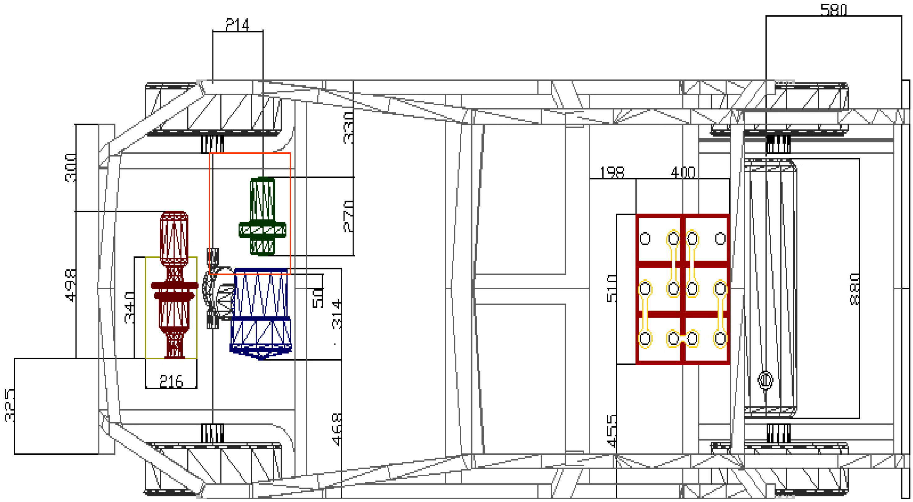
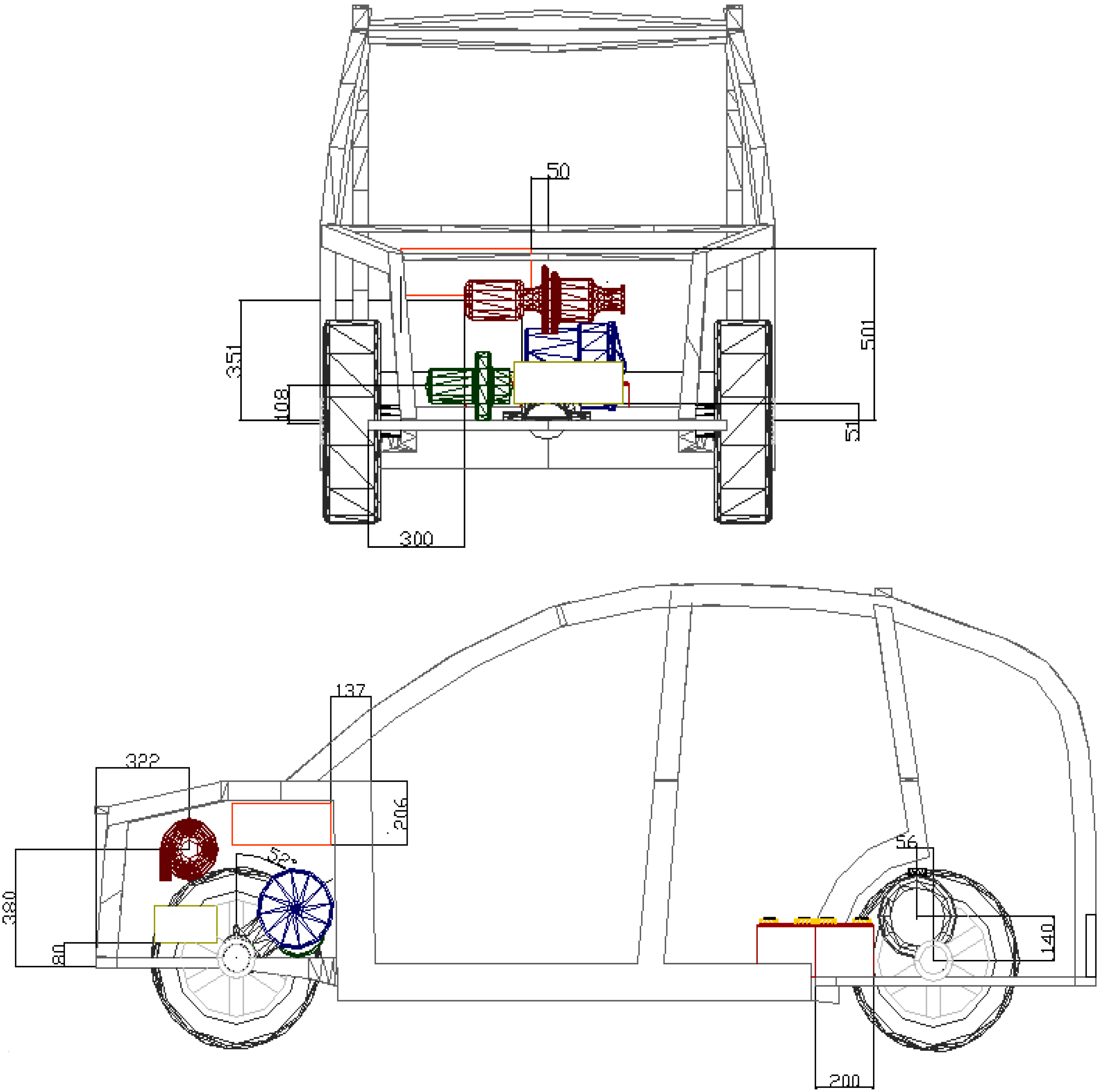
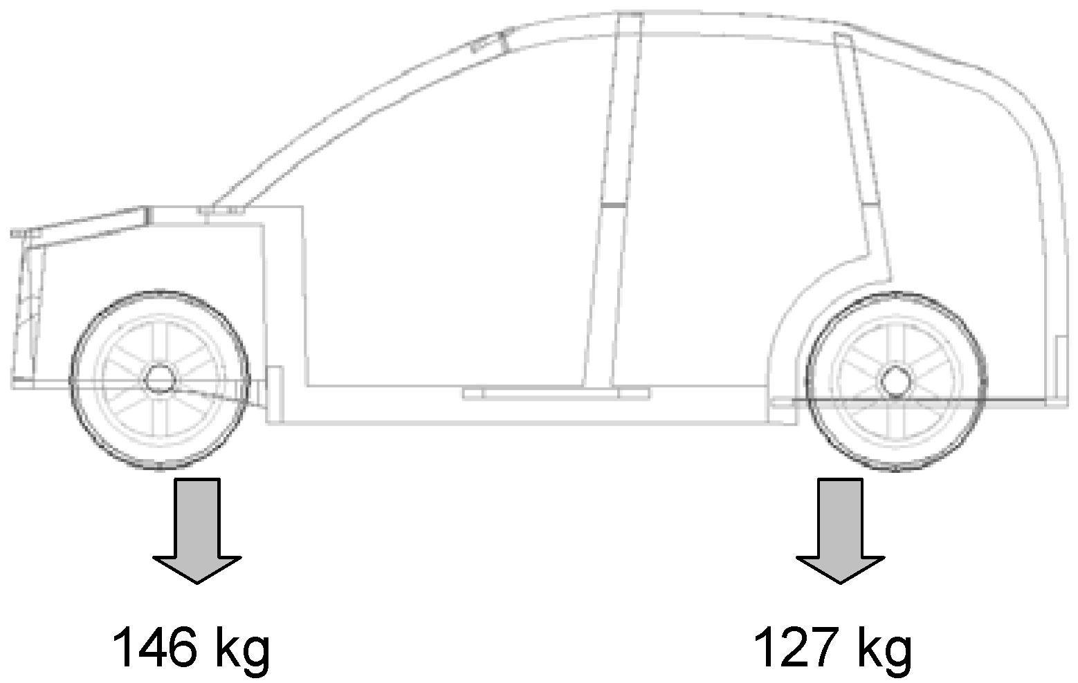
The weights and dimensions of all components are summarised in Table 8. There is a battery weight of 90 kg (six modules) that are placed underneath the rear seats. The gas tank is placed in the rear section while all the other components are housed in the front section (Figure 9). This configuration allows a weight distribution of 146 kg on the fore-carriage and 127 kg on the rear carriage (Figure 10).
Table 8. City Car Configuration.
W (kg)Dimensions (mm)
Battery Pack (6 mod.)90510 × 400 × 185
Electric Motor/Generator80Ø264 × 315
Inverter15410 × 340 × 138
GPL Fuel Tank37Ø270 × 880
Fly wheel3Ø200 × 270
Fly wheel motor13
GT 30 kW23Ø200 × 465
Regenerator12340 × 215 × 120
Figure 9. Views and main dimensions (in mm) of the LETHE© City Car configuration.
Energies 04 00368 g009aEnergies 04 00368 g009b
Figure 10. Weight distribution in the LETHE™ City Car configuration.
Energies 04 00368 g010

6. Lethe© Sedan

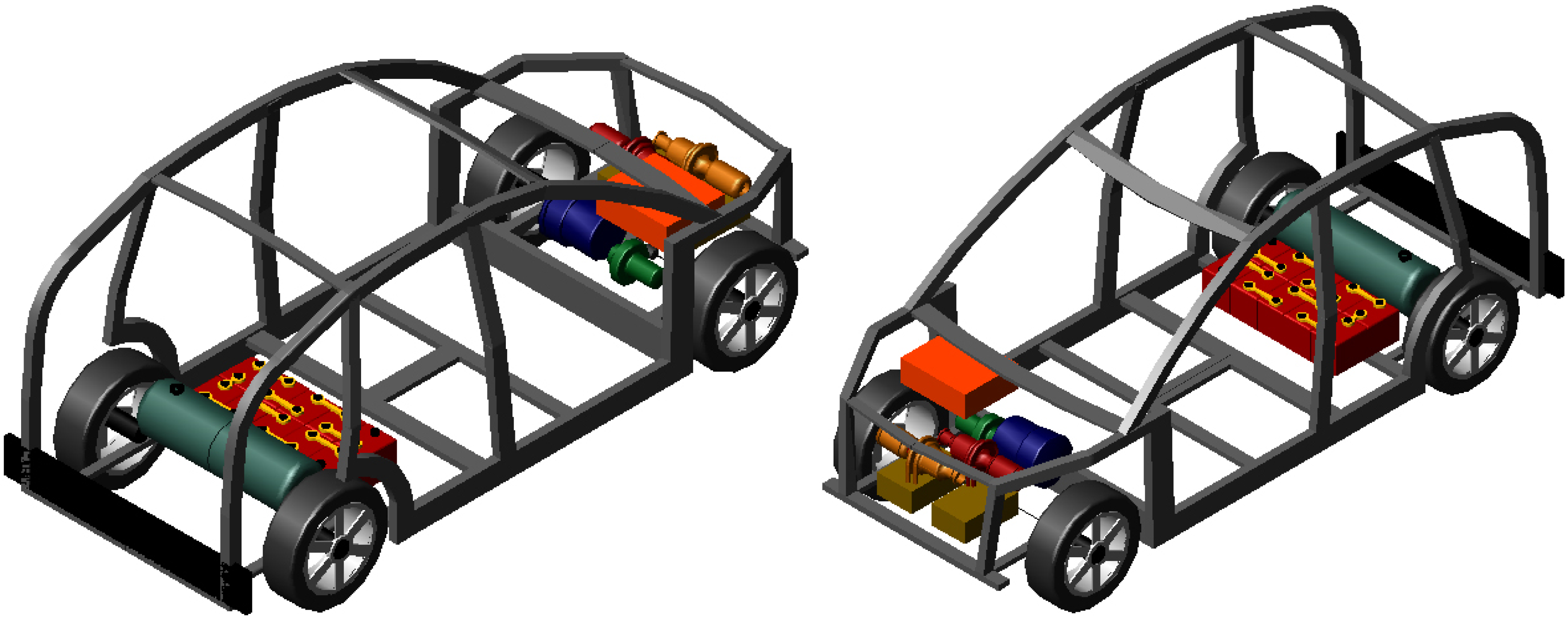
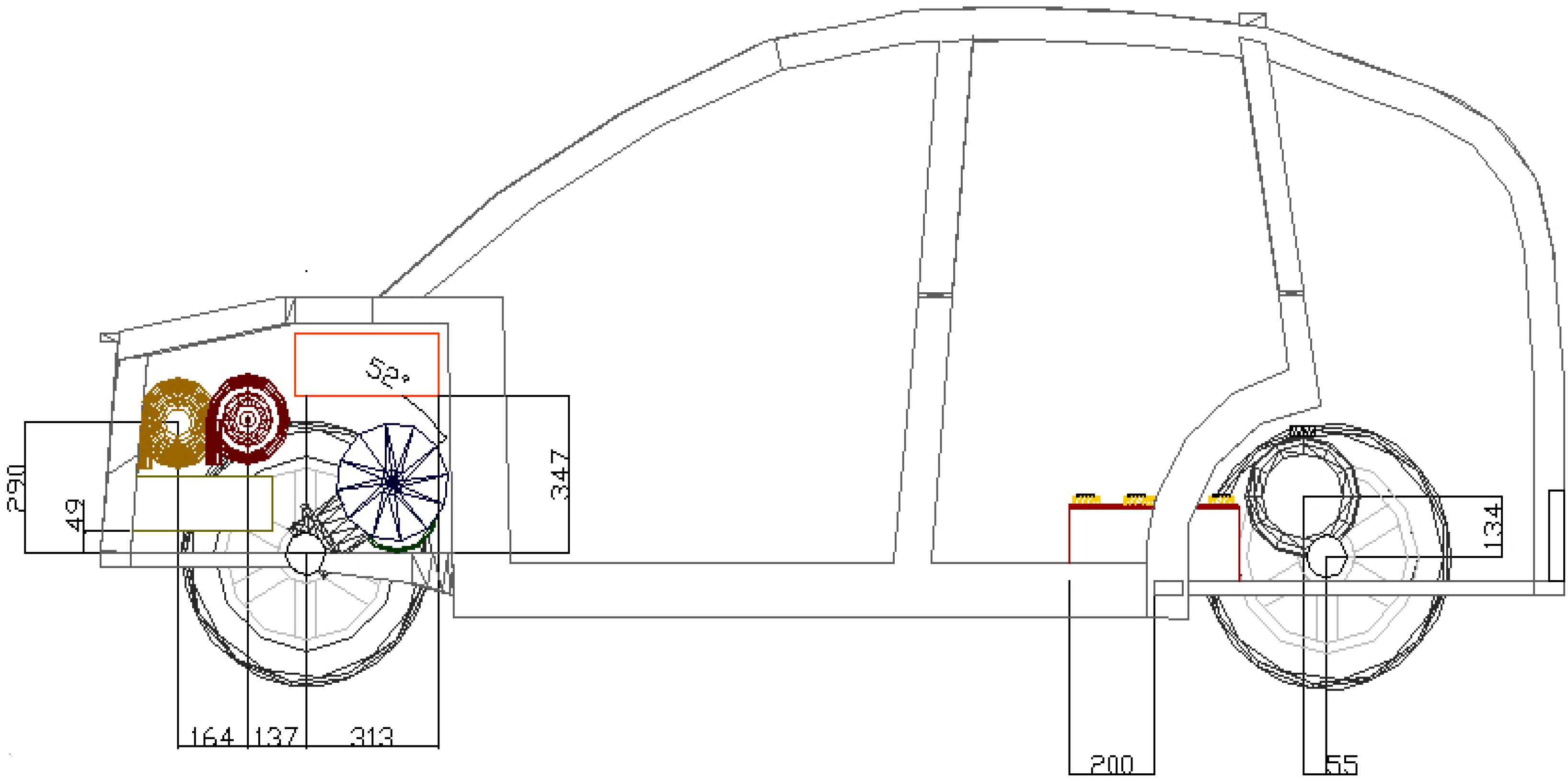
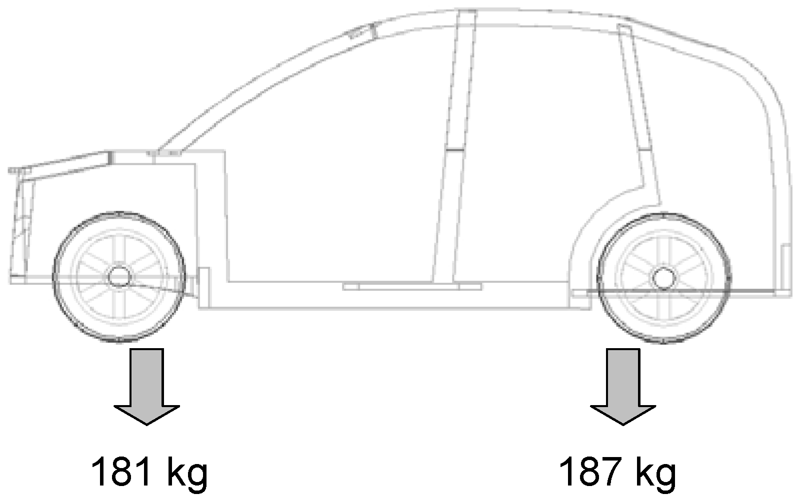
The weights and overall dimensions of the components are summarised in Table 9. The weight of the battery pack is 150 kg (10 modules) that are positioned underneath the rear seats. The gas tank is placed in the rear section while all the other components are housed in the front section (Figure 11,Figure 12). This distribution gives an overall weight of 181 kg on the fore-carriage and 187 kg on the rear carriage (Figure 13).
Table 9. Sedan Configuration.
W (kg)Dimensions (mm)
Battery Pack (10 mod.)150850 × 400 × 185
Electric Motor80Ø264 × 315
Convertitore15410 × 340 × 138
GPL Fuel Tank37Ø270 × 880
Fly wheel3Ø200 × 270
Fly wheel motor13
GT 30 kW (×2)23Ø200 × 465
Regenerator (×2)12340 × 215 × 120
Figure 11. Components distribution for the LETHE© Sedan configuration.
Energies 04 00368 g011
Figure 12. Views and main dimensions (in mm) of the LETHE© Sedan configuration.
Energies 04 00368 g012aEnergies 04 00368 g012b
Figure 13. Weight distribution in the LETHE© Sedan configuration.
Energies 04 00368 g013
In spite of the presence of the second GT unit, all the parts can still be comfortably installed in the area available under the Audi A2 bonnet. The two turbo-gas units were placed centrally and staggered in order to leave enough space for the air vents and the various connection pipes. The weights were equally distributed on the two wheel axles. In spite of the fact that the parts were closer than in the previous solutions, the motor area is still easily accessed and ventilated.

7. Techno—Economical Analysis

Once an annual average mileage is set, the annual costs can be determined for the proposed vehicle configurations, with reference to the GT and battery life, with the following assumptions:
Annual average mileage on urban roads: 10,000 km
Annual average mileage on mixed roads: 20,000 km
Km covered in a single urban mission: 10.7 km
Km covered in a single mixed mission: 178 km
Number of days operating per year: 300
Energies 04 00368 i001
Energies 04 00368 i002
Cost of vehicle: Cveic = 12,000 €
GT life: VGT = 40.000 h
Cost of GT group: 500 €/kW [12]
Cost of batteries: 4.2 €/kW [12]
Cost of specialised labourer Clab = 15 €/h
Laboratory hours: Hlab= 6 h/month
Cost of GT installation: CGT
Routine maintenance every 4000 hours of operational mode: cost K1 = 2% CGEN [12]
Extraordinary maintenance every 2000 hours of operational mode: cost K2 = 10% CGEN [12]
Total maintenance cost GT: Cmaint GT = K1 + K2
Battery mass: MBT
Cost of batteries: CBT
Number of battery recharges per mission: Nrec,miss
Number of potential battery missions: NBT = Ncycles 20%/Nrec,miss
Number of battery packs to be replaced each year: W= Nmiss,year/NBT
Cost of fuel (methane): Cfuel = 0.75 €/L [13]
The data for the two vehicles is provided in Table 10.
Table 10. Assumptions used for economic calculation.
Mission CharacteristicsURBANSEDAN
km/year10,00030,000
Nmission (mission per day)31
Working days30084
Nmission per year93584
Tmission (s)19596196
The number of cycles that a battery can support without undergoing serious changes to its electrical characteristics depends on the depth of discharge (DOD) it is subjected to. Generally, the plate data, for the number of cycles, refer to deep discharges, i.e., 80% discharges. For reasons already described in previous articles [4], the LETHE@ system foresees 20% depths of discharges and the number of cycles that the batteries can bear can be calculated using the following formula:
Energies 04 00368 i003
The calculations provide the following approximate results for installation costs of the hybrid traction system (see Table 11):
Table 11. Installation costs for battery pack.
Vehicle DataLETHE© City A*LETHE© City B*LETHE© Sedan
MBT (kg)7590150
Installed BT power (kW)11.2513.522.5
Nrec,miss1.3216
NBT8351102184
W1.1210.6
CBT (€)314376627
Installed GT power (kW)101025
CGT (€)5020502012,549
Cfuel,miss (€)0.250.257.2
* Two different solutions studied and described in [5].
To calculate the annual cost, the costs are discounted, usually assuming a six years of GT device operational life, the annual interest rate is set at = 5%, zero residual value and also presuming that the battery package are bought all together and at the same time as the TG. We thus obtain:
R = [(1 + i)6 · i]/[(1 + i)6 − 1] = 0.197
  • Cveic, a = R·Cveic
  • CGT, a = R·CGT
  • CBT,a = W·R·CBT
  • Cmanut GT,a = 2%CGT, a + 10%CGT, a
  • Clab,a = 12·Hlab·Clab
  • Ccomb,a = Nmiss,year·Cfuel,miss
The discounted costs in 2010 for the various configurations taken into consideration are compared with the ones for traditional and hybrid vehicles, for which average costs and consumptions are provided below in Table 12 and Table 13.
The same economic life and the same annual laboratory costs were assumed for these vehicles. The annual cost for fuel is calculated considering the respective average consumptions, the cost of fuel (petrol: 1.26 €/L; Diesel: 1187 €/L [14]) and presuming an annual mileage of 10,000 km per year for Honda hybrid vehicles and 20,000 km per year for the other models taken into consideration. The results are summarized in Table 14.
Table 12. Costs and consumption of some hybrid vehicles [13].
Hybrid VehiclesCost (€)Consumption (L/100 km)
Toyota Prius25,0004.3
Honda Insight20,0003.4
Honda Civic20,0003.4
Lexus RX400h46,0008
Ford Escort Hybrid26,0008.3
Table 13. Costs and consumption of some petrol and Diesel vehicles [13].
VehiclesCost (€)Consumption (L/100 km)
Renault Clio 2 TD12,0004.2
Lupo 1.2 TD15,0003.3
Toyota Yaris 1.4 TD14,0004.2
Ford Fiesta 1.4 TDCI14,0004.3
Daihatsu Cuore10,0004.6
Smart15,0004.7
Opel Corsa 1.212,0004.8
Table 14. Discounted costs at 2010.
VehiclesCveic,aCGT,aCBT,aCfuel,aClab,aCmaint GT,aCost per Year (€)
LETHE™ City A*236498936824010801195,159
LETHE™ City B*236498933724010801195,128
LETHE™ Sedan2364247240980710802977,429
Toyota Prius4925108410807,089
Honda Insight394042810805,449
Honda Civic394042810805,449
Lexus RX400h90632016108012,159
Ford Escape Hybrid5516209210808,688
Renault Clio 2236497910804,423
Lupo 1.2 TDI295576910804,804
Toyota Yaris 1.4 TD275897910804,817
Ford Fiesta 1.4 TDCI2758100210804,840
Daihatsu Cuore1970115910804,209
Smart2364118410804,629
Opel Corsa 1.22364121010804,654
The cost analysis confirms the LETHE™ system to be competitive compared to other hybrid proposals on the market. It can be noted how, since GT technology is a mature one, the cost of GT is one of the items that has the highest incidence on the final cost, in particular for the LETHE™ Sedan configuration (2,472 €). This is mainly due to the fact that this nominal power GT group (5–15 kW) cannot be found on the market, therefore a custom design using special materials is required. Any standard production of a series hybrid system should substantially reduce this cost. Compared with traditional vehicles, the latter have higher fuel costs than the LETHE™ vehicles, but the annual cost is lower due to their lower production costs.

8. Emission Testing

Owing to the large amount of attention currently paid to the environment, emission control, is a very important factor in the design of new combustion systems. The substances that must be kept under control are different in nature and origin and are characterised by:
  • PM particulate, in the form of volatile ash, soot and metal vapours;
  • Aerosols including sulphur oxides SO2 and SO3;
  • Unburnt (HC) or partially burnt hydrocarbons such as aldehydes (RCO2H);
  • Nitrogen oxides NO and NO2 (commonly known as “NOx”);
  • Carbon monoxide CO;
  • Greenhouse gas such as N2O and in particular carbon dioxide CO2.
The formation of these substances is clearly influenced by the type of fuel used: in fact, the elements present in the fuel are the ones found in smoke after combustion and form unsafe compounds. However, with the same amount of fuel, the thermo-physical characteristics of the combustion process are what determine the composition of combusted gas. Some of these substances can in fact be eliminated by simply controlling combustion. In this case, we are referring in particular to nitrogen compounds NOx and carbon monoxide CO, that are a problem for all the designers of combustion systems, together with unburnt hydrocarbons. These substances, in fact, can only be kept under control by completing combustion in particular conditions [15].

8.1. Calculation of Emissions for Lethe© Vehicle Configurations

Pollutant emissions are linked to several factors (such as the type of fuel, the combustion temperature, the air/fuel ratio), and can vary depending on operational conditions. The small amount of emissions data available on emissions in off-design conditions refer to a large-plant, where the combustion characteristics are different (pre-mixer, greater compression ratio), while the available data for small plants are only referred to stationary conditions. As an initial approximation, emissions from the LETHE© vehicles on the various routes were estimated using comparison with emissions from the Capstone turbo-generator C30HEV [8], having presumed that our GT unit has the same inlet temperature in the turbine, same compression ratio and same speed. The Capstone data (Table 15) are expressed in g/kWh and refer to a mass capacity of fuel of 2.36 g/s. By hypothesising a linear proportionality between mfuel (dependent on the PGT) and the amount of pollutant emitted, emissions at certain set power Pj can be obtained (corresponding to certain mi) that correspond to the cycle time-steps.
Table 15. Emissions from the Capstone C30HEV unit.
Emissions (g/kWh)CNGPropane
NOx0.1940.396
HC0.3130.313
CO0.3060.134
PM0.0030.003
It was also presumed that the GT unit is regulated by variation of the fuel capacity, maintaining the turbine inlet temperature constant. For this reason, the emissions in the Off-Design operational mode will also be calculated using linear proportionality with emissions at the nominal point of the C30HEV, increased by a safety factor that is presumed to be 50%. With reference to NOx emissions, for the C30HEV:
CC30HEV (g/s) → NOx, C30HEV (g/kWh)
Therefore,
Energies 04 00368 i004
indicating the instant consumption of the GT unit (depending on the power issued and by ηGT) with Ct, LETHE.
The total NOx emissions are obtained by adding these all “instant” emissions over the entire mission, divided by the GT switch-on time:
Energies 04 00368 i005
Finally, in order to obtain the emission level in g/km, as stated by the EURO regulations on emissions:
Energies 04 00368 i006
By repeating the same procedure for other substances, the results obtained for a LETHE© Sedan vehicle configuration on a mixed route can be provided (Table 16).
Table 16. Emissions from the LETHE© Sedan on a mixed route.
PollutantsEmissions (g/kWh)Emissions (g/km)
NOx0.06800.0120
HC0.10990.0194
CO0.10720.0190
PM0.00110.0002
An initial comparison of the results between the two tables shows that the LETHE© Sedan emissions are 65% lower than the C30HEV emissions. Although this estimate must be considered as an initial approximation, this result is due to the fact that the GT group supplies less power (10 and 15 kW approximately of nominal power respectively), in addition to having a higher performance, 44% (“on paper”) compared to 29% (“real”) of the C30HEV. Moreover, the Capstone emissions refer to the consumption of fuel at the car’s nominal point, while the emissions of GT unit on the LETHE© Sedan are the sum of the emissions from instant consumptions. The Off-Design conditions of the turbogas unit, and the efficiency decrease are considered in the calculation for the fuel consumption and are only estimated, increased by 50%. Finally, it is necessary to consider switch-on times of the GT units, compared to the mission time, which are 4138 s for the 10 kW GT and 4641 s for the 15 kW GT, compared to the 6200 s of mission duration. The GT switch-on operations also include the time needed at the “end of mission” to recharge the battery package to the initial SOC. About 1/4 of the mission is therefore carried out in electrical mode, with zero emissions, a condition that naturally contributes to reducing emissions. Table 17 shows the limit values for emissions set by Directive 98/69/CE [16].
Table 17. EURO Directives on Emissions.
NormativeNOx (g/km)HC (g/km)CO (g/km)PM (g/km)
EURO 50.040.050.50.0125
EURO 40.080.110.025
By comparing the emissions obtained for the LETHE© Sedan vehicles with the EURO5 directive, a reduction of 70% of NOx, 61% of HC, 96% of CO and 98% of PM is obtained. Considering that emissions are halved with each new EURO Directive, the LETHE© Sedan vehicle would be compatible with the future EURO 7. Emissions for the LETHE© City car configuration, on urban routes, are obtained by similar calculations, and are shown in Table 18.
Table 18. Emissions from the LETHE™ City Car on urban routes.
PollutantsEmissions (g/kWh)Emissions (g/km)
NOx5.81 × 10−26.18 × 10⁻³
HC9.39 × 10−29.99 × 10⁻³
CO9.17 × 10−29.75 × 10⁻³
PM9.17 × 10−49.75× 10⁻⁵
Table 19 shows the percentage reductions of pollutant substances compared to the C30HEV and the EURO 5 Directive. In addition to the reasons provided above, in order to justify such low emissions, it is necessary to consider the switch-on time of the GT unit. On an urban mission during which 11 km are covered in 1959 s, the GT supplies power for only 440 s (including the time required to recharge the battery package at the end of the mission), therefore more than 3/4 of the mission is performed in electrical mode. The emissions has to be calculated on the entire route, considering both the electrical mode and the hybrid mode (GT switched on), and thanks to the net prevalence of electrical drive, we obtain a low pollutant substances emissions values (Table 20).
Table 19. Percentage reduction of emissions of the LETHE™ City Car.
C30HEVEURO 5
NOx−70%−84.5%
HC−70%−80.6%
CO−70%−98%
PM−70%−99.2%
Table 20. Lethe@ data.
ConsumptionPollutant Emissions
(km/L)(L/100 km)(g/kWh)
283.5171NOx−80%
HC−80%
CO−90%
PM−90%
Table 21. Capstone C30HEV (diesel) emissions [8] at full load (g/kWh).
Emissions UnitsEURO 5 (2008)EURO 6 (2013)Capstone C30HEV
NOx2.000.500.60
CO1.501.501.17
PM0.460.130.004
Table 22. CO emissions of commercial passenger sedan (g/km).
EmissionPunto 1.2 60cv (GPL)Punto 1.4 Dynamic (GPL)Passat TSI 1.4 EcofuelCivic Hybrid 1.3 iInsight 1.3Prius 1.5 16V
NOx [ppm]n.a.n.a.n.a.n.a.n.a.n.a
CO [g/km]119115123109101104
PM [ppm]n.a.n.a.n.a.n.a.n.a.n.a
The analysis of the last two tables (Table 21 and Table 22) indicates that a Captone 30HEV gas turbine has lower emissions in comparison with those defined by the European directives (it would readily meet the EURO 6 limits). The comparison with the other currently existing commercial passenger sedans (Table 18 and Table 22) is also positive, thanks to the peculiarity of the operational mode of the turbogas group, which is not designed to supply power to the drivetrain, but rather to recharge the battery package (i.e., as a range extender) or to complement the battery power during power surges.
9. Conclusions

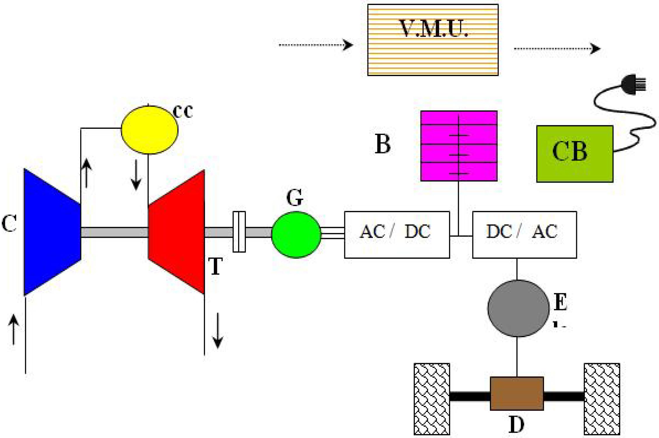
The feasibility and availability of the Lethe™ hybrid passenger sedan (see Figure 14 for the conceptual layout) has been confirmed and positively evaluated. The most important innovation in this project are the advantages offered by a GT device in replacement of the traditional thermal motor (ICE). This is not a complete “revolution” in the concept of cars as we know it today, but about a simple reorganisation of the components. Advantages that can be summed up in terms of weight, size and the opportunity of utilization of a multi-fuel motor that can work with all types of fuel that are currently available on the market, thus reducing the economic effects of price fluctuations for the various types of fuel. By returning to all the analyses carried out in this article, we can summarise everything in the Table 20, which shows the consumption and emissions of Lethe™ hybridised vehicle according to the described procedure. The table contains data obtained by previous simulations and various assumptions and calculations made [1,2,3,4,5]. It notes a consumption reduction of about 30%, for a hybrid city car powered by methane compared to current commercial production vehicles. With regards to emissions, we have highlighted the drastic reduction in all the main pollutants emitted from the motor compared to the values permitted by the current rules, made possible due to optimisation of fuel for a thermal motor that operates at a nominal point. The HS configuration makes the use of GT device possible. We have been proposing hybridisation studies for commercial vehicles applied to cargo and passenger transport for several years, studies that have involved trains, trucks and cars and that have emphasised the feasibility of such conversions in both energy and economic terms. In a global context of reduction: greenhouse gas emissions, consumption of fossil fuels, of city pollution, it is clear that the benefits introduced by the HS vehicle would provide an immediate reply to the most mandatory environmental subjects. If the close relationship between a series hybrid vehicle and an electrical vehicle are taken into consideration in a mid-long term view, it becomes apparent that the change from traditional vehicle to HS is the natural change to provide a large-scale thrust to all those technological and commercial aspects that still slow down the development of electrical vehicles.
Figure 14. Conceptual layout of the LETHE© hybrid vehicle series. C compressor, T turbine, R Regenerator, CC Combustion Chamber, G turbogenerator, AC/DC inverter, B batteries, CB external battery charging, M electrical motor, D differential, VMU vehicle management unit [1,2,3,4,5].
Energies 04 00368 g014

Nomenclature

C
Cost (€)—Section 6; Consumption—Section 7
DOD
Depth of Charge
E
Energy (J)
GPL
Gas Petroleum Liquid
GT
Gas Turbine set
H
Hours (s)
HS
Hybrid Series
ICE
Internal Combustion Engine
KERS
Kinetic Energy Recover System
LETHE
Low Emission Turbo Hybrid Electric Vehicle
M
Mass (kg)
N
Number of mission, number of cycles
PM
Particulate
R
Radius (m)—Section 2; Cost—Section 6
SOC
State of Charge
UDR1
University of Roma 1
V
Component Lifetime
W
Weight—Section 4; Battery Package Numbers—Section 7

Greek Letters

k
constant
δ
density

Subscripts

p
peak

References

  1. Capata, R.; Coccia, A. Procedure for the design of a Hybrid-Series vehicle at UDR1 and the Hybridization Degree choice. Energies 2010, 3, 450–461. [Google Scholar] [CrossRef]
  2. Capata, R.; Sciubba, E. A Gas Turbine-Based Hybrid Vehicle-Part II: Technological and configuration issues. J. Eng. Gas Turbines Power 2003, 125, 777–782. [Google Scholar] [CrossRef]
  3. Capata, R.; Sciubba, E. An innovative solution for suburban railroad transportation: The gas turbine hybrid train. Int. J. Thermodyn. 2005, 8, 55–66. [Google Scholar]
  4. Capata, R.; Sciubba, E. The concept of the Gas Turbine-based Hybrid Vehicle: System, Design and Configuration Issues. IJER 2006, 30, 671–684. [Google Scholar]
  5. Capata, R.; Lora, M. The Comparative assessment and selection of an “optimal” configuration for a Gas Turbine-Based Hybrid city car. JERT 2008, 129, 107–117. [Google Scholar]
  6. Hawker Energy, Genesis Catalogue. Available online: http://www.enersysreservepower.com/ (accessed on 22 February 2011).
  7. Homepage of Capstone Turbine Corporation. Available online: http://www.interstatepower.us/Capstone/Document/Library/Application/Guides/ (accessed on 24 February 2011).
  8. GT30HEV gas turbine. Available online: http://www.interstatepower.us/Capstone/Document/Library/Application/Guides/480009_HEV_Application_Guide.pdf (accessed on 25 February 2011).
  9. Homepage of Autogas Italia. Available online: http://www.autogasitalia.it/ (accessed on 22 February 2011).
  10. Homepage of Audi-Club.dk. Available online: http://www.audi-club.dk/ (accessed on 22 February 2011).
  11. Homepage of Audi. Available online: http://www.cgworld.ru/modules.php (accessed on 22 February 2011).
  12. Pede, G. Personal Communication, ENEA: Rome, Italy, March 2009.
  13. Homepage of motorbox.com. Available online: http://www.motorbox.com/Auto/Prezzi_Nuovo/ (accessed on March 2010).
  14. Homepage of Prezzi Banzina. Available online: http://www.prezzibenzina.it/ (accessed on 22 February 2011).
  15. Ciaralli, F. Evaluation and Determination of Efficiency Index in the Combined and TurboGas Power Plant. Master Degree Thesis, University of Roma, Rome, Italy, 2001. [Google Scholar]
  16. Homepage of Automobile Club Italy. Available online: http://www.aci.it (accessed on 22 February 2011).