CFD Investigation into Diesel PCCI Combustion with Optimized Fuel Injection

Abstract
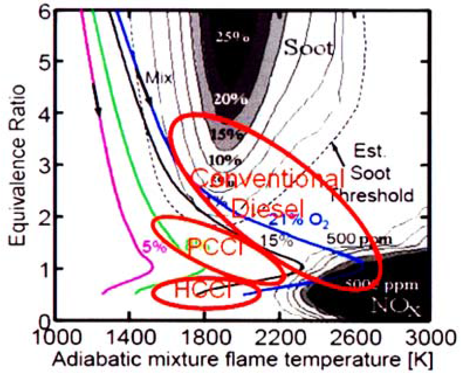
:1. Introduction

2. Numerical Methods
2.1. Methodology

| Turbulent Model | RNG k-ε Model [11] |
| Break Up Model | KH-RT Model [13] |
| Collision Model | Nordin Model [14] |
| Splash Model | Han et al. Model [15] |
| Heat Transfer (wall) | Han-Reitz Model [12] |
| Combustion | CHEMKIN [16] |
| Fuel Chemistry | Reduced n-Heptane Mechanism [18] |
| Soot Model | Phenomenological Model [17] |
| NOx Mechanism | Extended Zeldovich Mechanism [17] |
2.2. Computational Grid

3. Engine Specifications
| Engine Type | 4 valve HSDI diesel |
| Bore × Stroke | 82.0 mm × 90.4 mm |
| Compression Ratio | 16.0:1 |
| Displacement | 477 cm3 |
| Combustion Chamber | Open Crater Type Bowl |
| Intake Ports | 1 helical + 1 direct port |
| Swirl Ratio (at IVC) | 1.83 ~ 3.30 (1.85) |
| Piston Bowl Diameter | 48 mm |
| Squish Height | 1.61 mm |
| IVO/IVC | 350 °CA ATDC/−142 °CA ATDC |
| EVO/EVC | 142 °CA ATDC/368.5 °CA ATDC |
| Injector Type | Electro-hydraulically Controlled |
| Nozzle Type | Dual guided VCO |
| Injection Pressure | 1,800 bar maximum |
| Flow Number | 400 cm3/30 s @ 100 bar |
| Included Angle | 120°, 130°, 140° |
| Number of Orifices | 6 |
| Orifice Diameter | 0.11 mm |
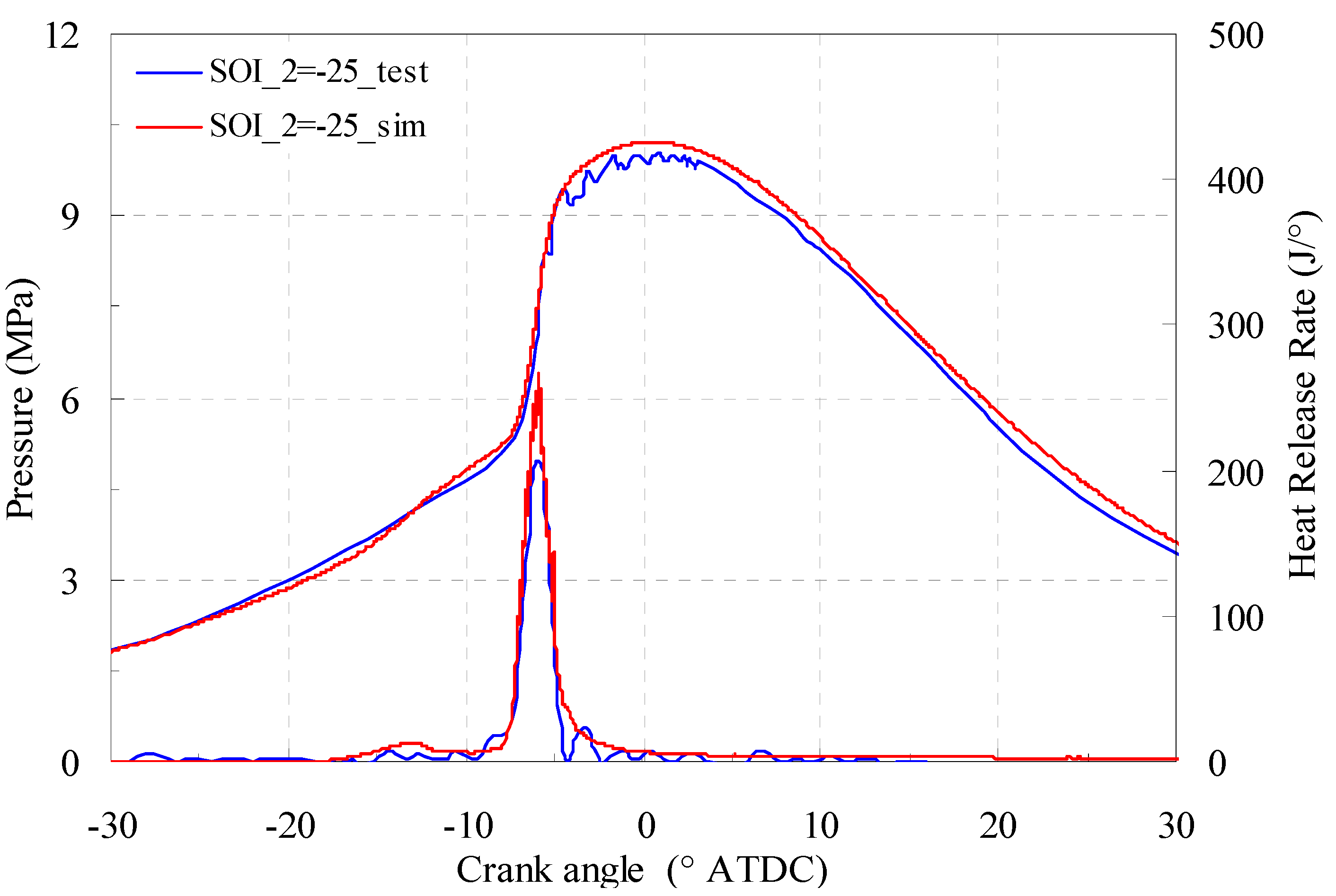
4. Model Validation

5. Results and Discussion
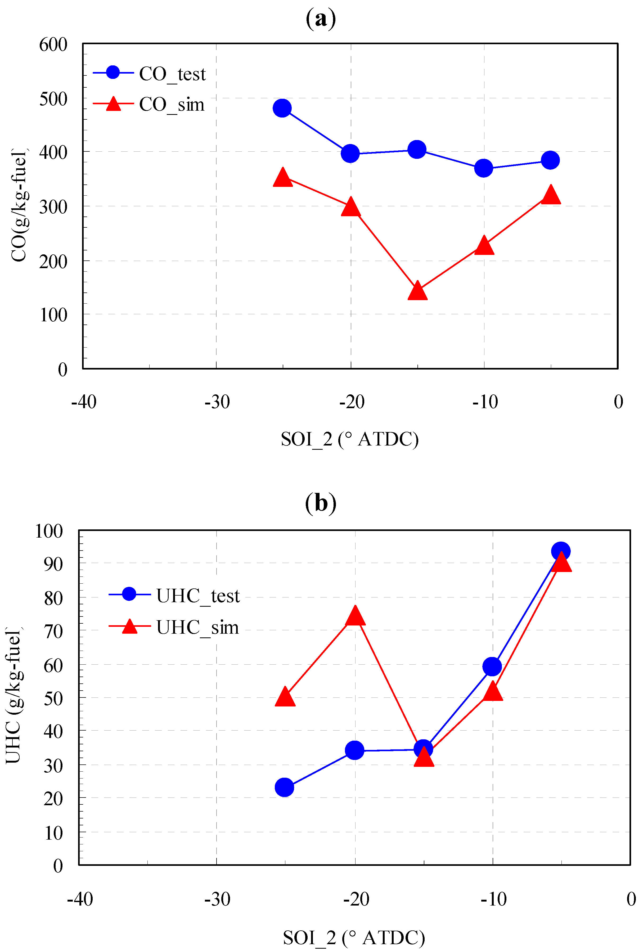
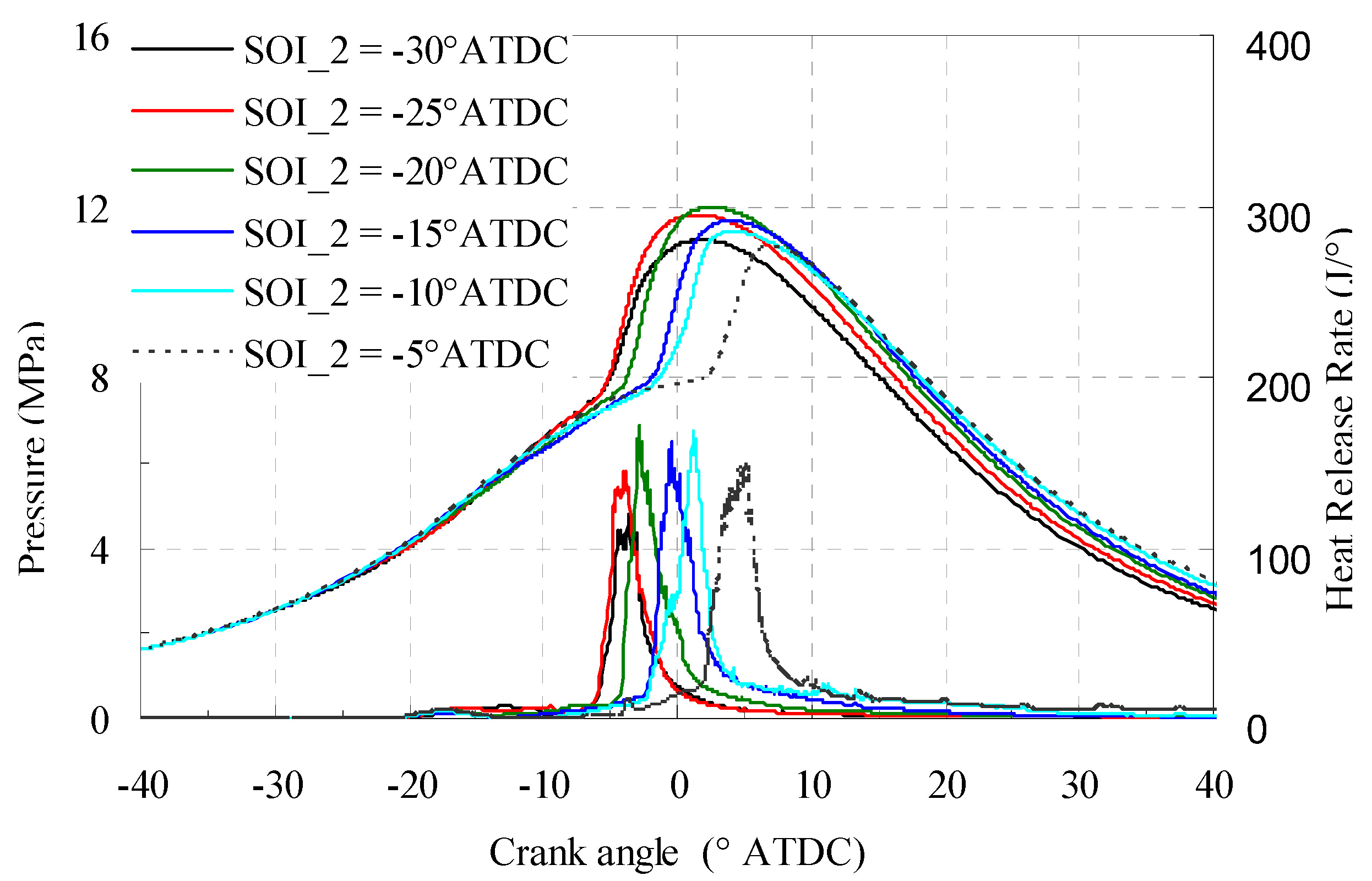
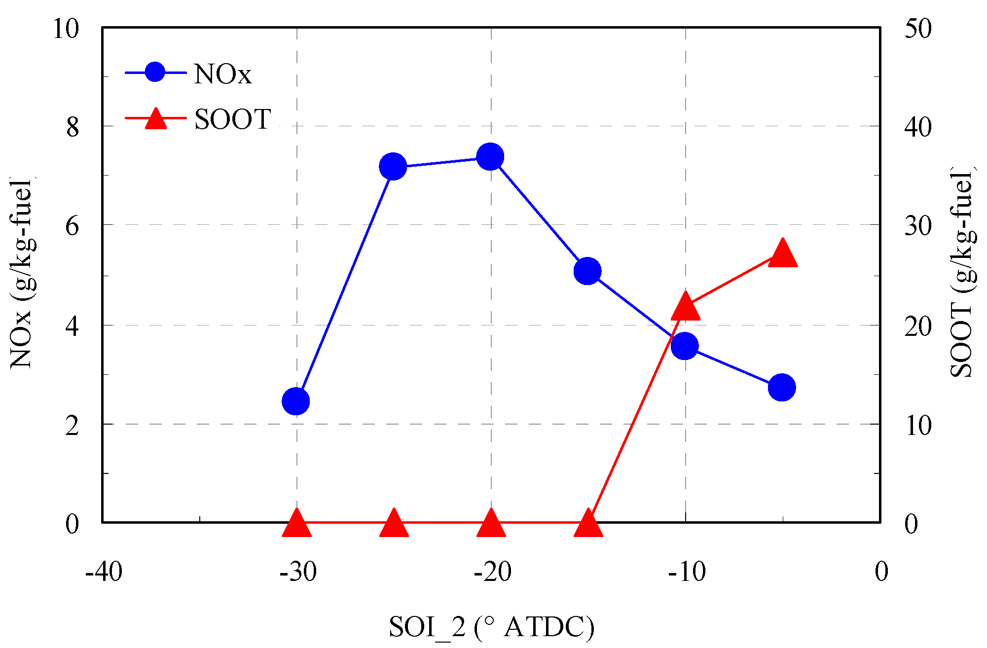
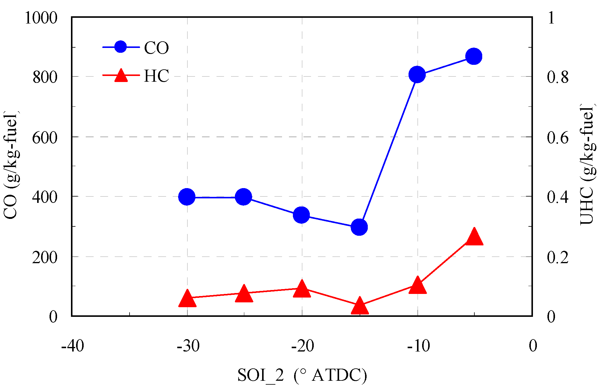
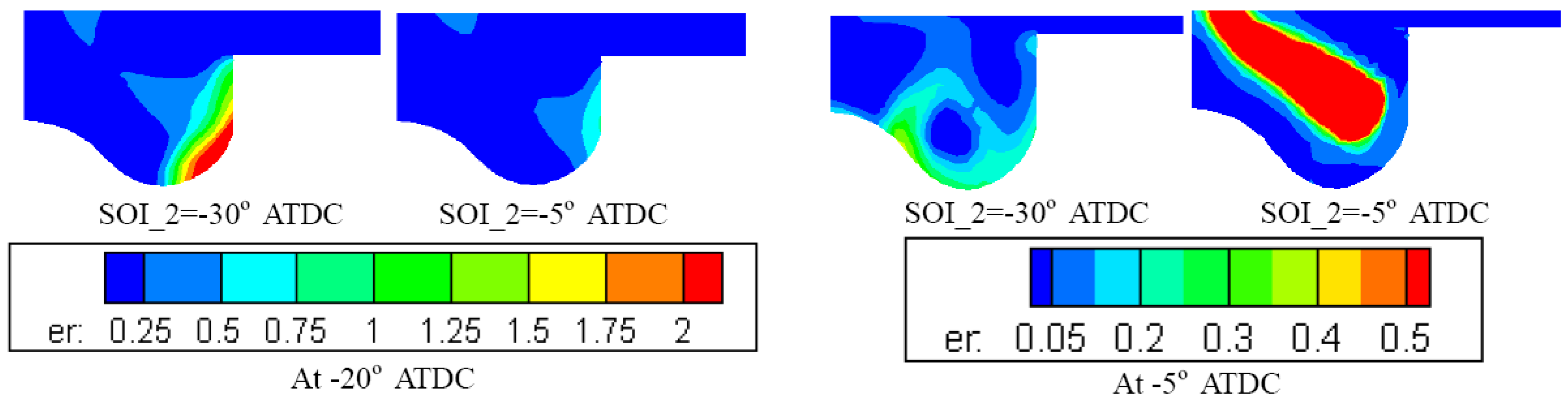
5.1. Baseline—Sweep of Second Pulse Timing

| Engine Speed | 2500 rpm |
| IVC Temperature | 360 K |
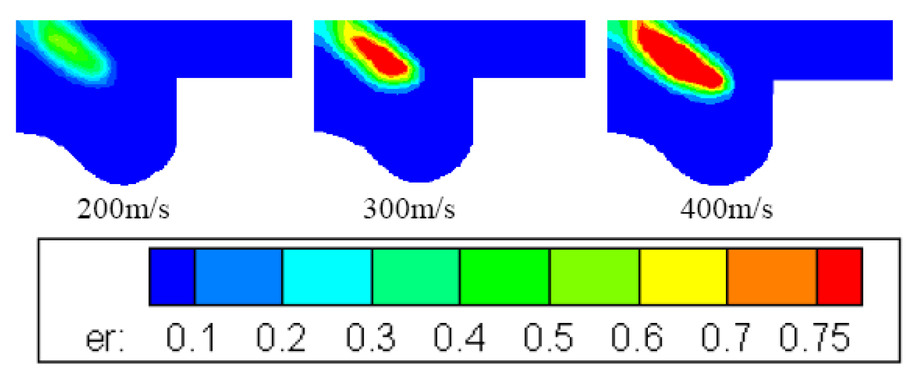
| Velocity at injector | 400 m/s |
| Fuel Mass | 30 mg/cycle |
| SOI_1 | −40° CA ATDC |
| SOI_2 | −30°~−5° CA ATDC |
| Injection Duration_1 | 3° CA |
| Injection Duration_2 | 5.04° CA |
| Fuel Mass of 1st Injection | 20% |
| Included Angle | 120° |
| Swirl Ratio | 1.83 |
| EGR Rate | 35% |


5.2. Effect of Injection Splitting Proportion
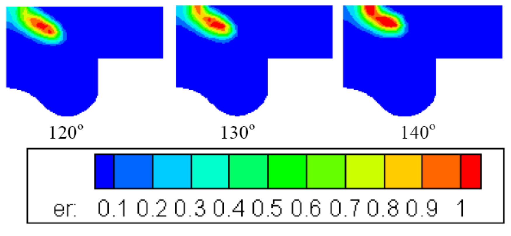
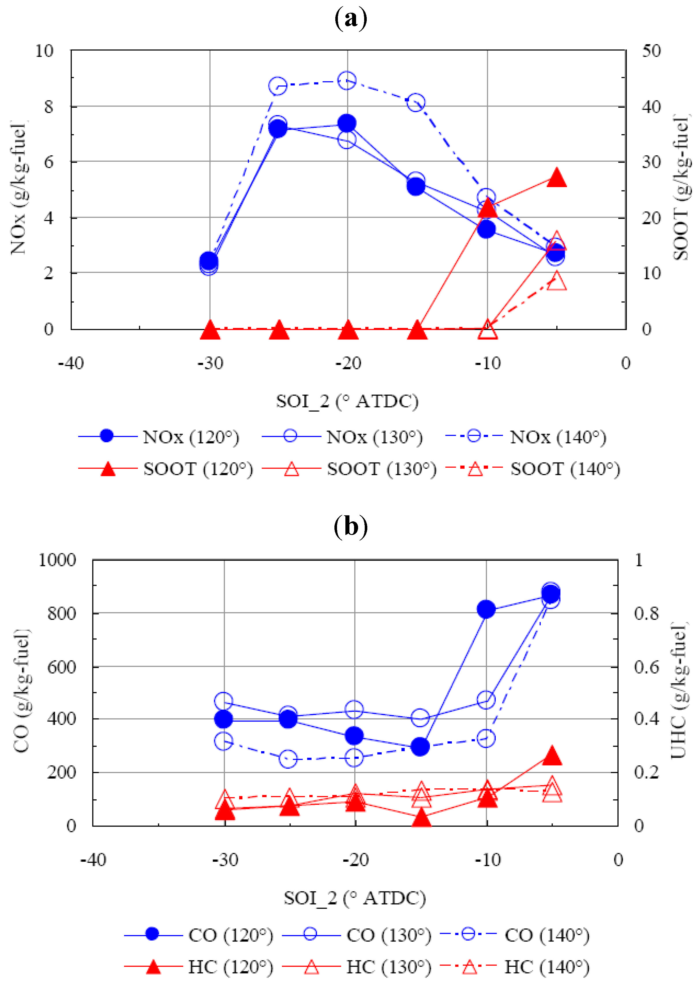
5.3. Effect of Spray Angle


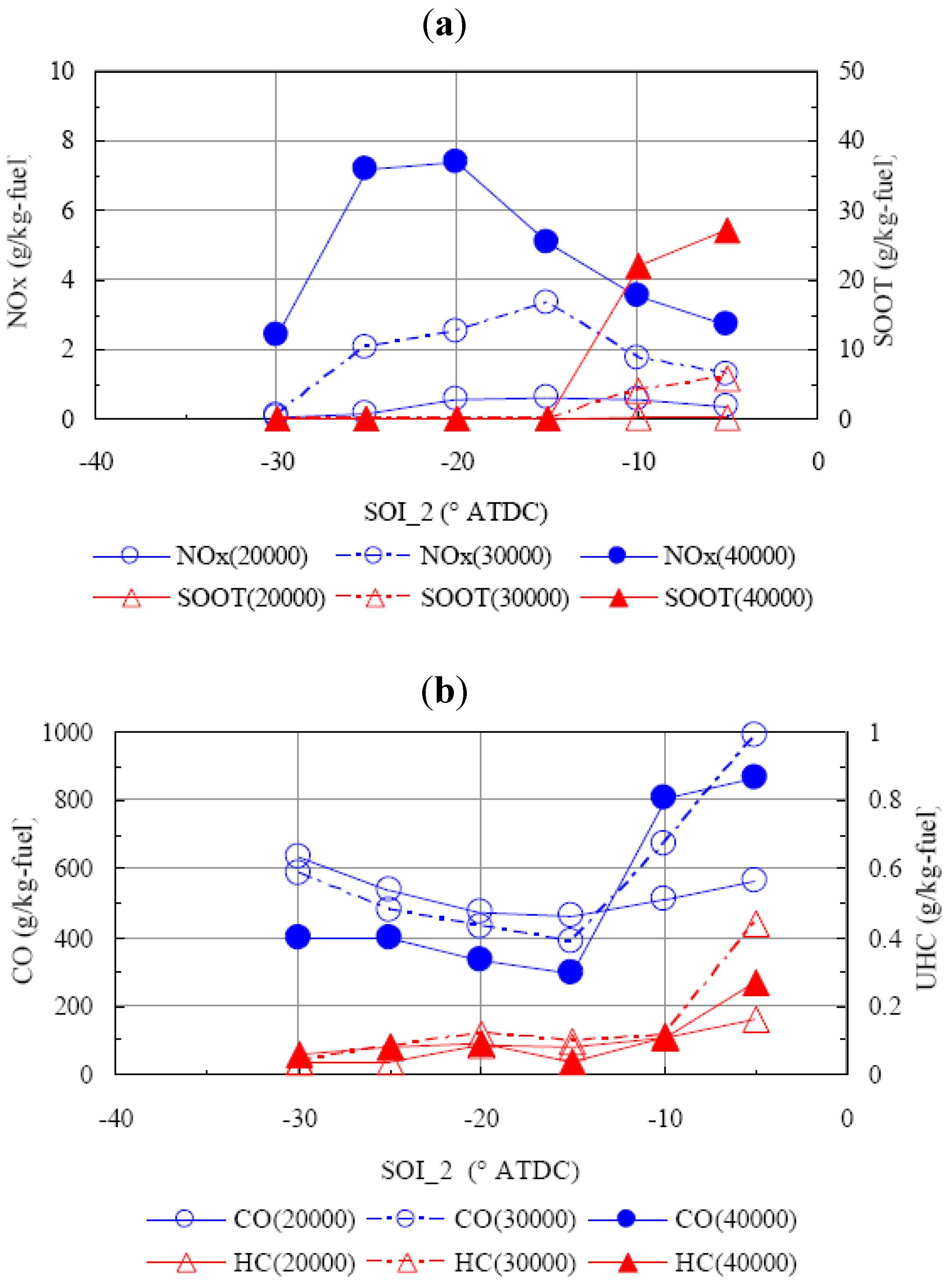
5.4. Effect of Injection Velocity


6. Conclusions
- ○
- The timing of second injection and the fuel velocity at the injector significantly impact the combustion and emissions due to the considerable changes to the mixing process and fuel distribution in the cylinder. A “key timing” exists between the start of ignition and the end of first heat release phase, where the trend of emissions’ varies according to the start of the second (main) injection.
- ○
- The more fuel injected in the first injection, the more homogeneous the mixture is. For the cases where all the fuel was injected before the start of ignition, reducing the fuel amount in the first injection can achieve lower NOx emissions. To the contrary, when increasing the fuel amount in the first injection one can obtain better NOx emissions when the start of the main injection is retarded after ignition.
- ○
- A large inclusion angle shows advantages in achieving low soot, CO and UHC emissions, but display some disadvantages in NOx control.
Acknowledgments
Acronyms
| ATDC | after top dead centre; |
| CO | carbon monoxide; |
| EGR | exhaust gas recirculation; |
| EVC | exhaust valve close; |
| EVO | exhaust valve opening; |
| HCCI | homogeneous charge compression ignition; |
| HC | hydrocarbon; |
| HRR | heat release rate; |
| HSDI | high speed direct injection; |
| HTHR | high temperature heat release; |
| ISFC | indicated specific fuel consumption; |
| IVC | intake valve close; |
| IVO | intake valve opening; |
| LTC | low temperature combustion; |
| NOx | nitrogen oxides; |
| PCCI | premixed charge compression ignition; |
| PRR | pressure rise rate; |
| TDC | top dead centre; |
| TSC | two-stage combustion; |
| UHC | unburned hydrocarbon |
References
- Okude, K.; Mori, K.; Shiino, S.; Moriya, T. Premixed Compression Ignition (PCI) Combustion for Simultaneous Reduction of NOx and Soot in Diesel Engine. SAE Trans. 2004, 113, 1002–1013. [Google Scholar]
- Lechner, G.A.; Jacobs, T.J.; Chryssakis, C.A.; Assanis, D.N.; Siewert, R.M. Evaluation of Narrow Spray Cone Angle, Advanced Injection Timing Strategy to Achieve Partially Premixed Compression Ignition Combustion in a Diesel Engine. SAE Trans. 2005, 114, 394–404. [Google Scholar]
- Kanda, T.; Hakozaki, T.; Uchimoto, T.; Hatano, J.; Kitayama, N.; Sono, H. PCCI Operation with Early Injection of conventional Diesel Fuel. SAE Trans. 2005, 114, 584–593. [Google Scholar]
- Jacobs, T.; Bohac, S.; Assanis, D.N.; Szymkowicz, P.G. Lean and Rich Premixed Compression Ignition Combustion in a Light-Duty Diesel Engine. SAE Trans. 2005. [Google Scholar] [CrossRef]
- Kamimoto, T.; Bae, M. High Combustion Temperature for the Reduction of Particulate in Diesel Engines. SAE Trans. 1988. [Google Scholar] [CrossRef]
- Sun, Y. Diesel combustion optimization and emissions reduction using adaptive injection strategies (AIS) with improved numerical models. Ph.D. Thesis, University of Wisconsin, Madison, WI, USA, 2007. [Google Scholar]
- Lee, S.; Reitz, R.D. Spray Targeting to Minimize Soot and CO Formation in Premixed Charge Compression Ignition (PCCI) Combustion with a HSDI Diesel Engine. SAE Trans. 2006. [Google Scholar] [CrossRef]
- Kokjohn, S.L.; Reitz, R.D. A Computational Investigation of Two-stage Combustion in a Light-Duty Engine. SAE Int. J. Engines 2008, 1, 1083–1104. [Google Scholar]
- Koci, C.P.; Ra, Y.; Krieger, R.; Andrie, M.; Foster, D.E.; Siewert, R.M.; Durrett, R.P. Multiple-Event Fuel Injection Investigations in a Highly-Dilute Diesel Low Temperature Combustion Regime. SAE Int. J. Engines 2009, 2, 837–857. [Google Scholar]
- Amsden, A.A. In Kiva-3v: A Block-Structured Kiva Program for Engines with Vertical or Canted Values; Technical Report Number LA-13313-MS. Los Alamos National Laboratory: Los Alamos, NM, USA, 1997. [Google Scholar]
- Han, Z.Y.; Reitz, R.D. Turbulence Modeling of Internal Combustion Engines Using RNG K-E Models. Combust. Sci. Technol. 1995, 106, 267–295. [Google Scholar] [CrossRef]
- Han, Z.Y.; Reitz, R.D. A temperature wall function formulation for variable-density turbulence flows with application to engines convective heat transfer modeling. Int. J. Heat and Mass Transfer 1997, 40, 613–625. [Google Scholar] [CrossRef]
- Ricart, L.M.; Reitz, R.D.; Dec, J.E. Comparisons of diesel spray liquid penetration and vapor fuel distributions with in-cylinder optical measurements. Trans. ASME J. Engn. Gas Turbines Power 2000, 122, 588–595. [Google Scholar] [CrossRef]
- Nordin, N. Complex chemistry modeling of diesel spray combustion. Ph.D. Thesis, Chalmers University of Technology, Goteborg, Sweden, 2001. [Google Scholar]
- Han, Z.Y.; Xu, Z.; Trigui, N. Spray/wall interaction models for multidimensional engine simulation. Int. J. Engine Res. 2000, 1, 127–146. [Google Scholar] [CrossRef]
- Kee, R.J.; Rupley, F.M.; Meeks, E.; Miller, J.A. CHEMKIN-III: A FORTRAN chemical kinetics package for the analysis of gas phase chemical and plasma kinetics. Technical Report for Sandia National Laboratories: Albuquerque, NM, USA, 1996. [Google Scholar]
- Jia, M.; Peng, Z.J.; Xia, M.Z. Numerical Investigation of Soot Reduction Potentials with Diesel Homogeneous Charge Compression Ignition Combustion by An Improved Phenomenological Soot Model. J. Automot. Eng. 2009, 223, 396–399. [Google Scholar]
- Patel, A.; Kong, S.C.; Reitz, R.D. Development and validation of reduced reaction mechanism for HCCI engine simulation. SAE Int. 2004. [Google Scholar] [CrossRef]
- Abani, N.; Kokjohn, S.L.; Park, S.W.; Bergin, M.; Munnannur, A.; Ning, W.; Reitz, R.D. An improved Spray Model for Reducing Numerical Parameters Dependencies in Diesel Engine CFD Simulations. SAE Int. 2008. [Google Scholar] [CrossRef]
- Kim, Y.J.; Lee, S.H.; Cho, N.H. Effect of Air Motion on Fuel Spray Characteristics in a Gasoline Direct Injection Engine. SAE Int. 1999. [Google Scholar] [CrossRef]
- Lee, S.S. Investigation of two low emissions strategies for diesel engines: premixed charge compression ignition (PCCI) and stoichiometric combustion. Ph.D. Thesis, University of Wisconsin, Madison, WI, USA, 2006. [Google Scholar]
© 2011 by the authors; licensee MDPI, Basel, Switzerland. This article is an open access article distributed under the terms and conditions of the Creative Commons Attribution license (http://creativecommons.org/licenses/by/3.0/).
Share and Cite
Peng, Z.; Liu, B.; Wang, W.; Lu, L. CFD Investigation into Diesel PCCI Combustion with Optimized Fuel Injection. Energies 2011, 4, 517-531. https://doi.org/10.3390/en4030517
Peng Z, Liu B, Wang W, Lu L. CFD Investigation into Diesel PCCI Combustion with Optimized Fuel Injection. Energies. 2011; 4(3):517-531. https://doi.org/10.3390/en4030517
Chicago/Turabian StylePeng, Zhijun, Bin Liu, Weiji Wang, and Lipeng Lu. 2011. "CFD Investigation into Diesel PCCI Combustion with Optimized Fuel Injection" Energies 4, no. 3: 517-531. https://doi.org/10.3390/en4030517