1. Introduction
Energy consumption has been steadily increasing year by year over the last decades. In particular, the demand for electrical energy is increasing due to the spread of home electrical appliances. Also, new types of demand for electricity appear with growing use of plug-in hybrid electric vehicles (PHEVs) and electric vehicles (EVs). However, environmental issues necessarily restrict energy consumption. As a result, alternative energy sources need to be considered, and the utilization of natural and renewable energy sources have been promoted. Examples of natural and renewable energy sources include photovoltaics, wind-power generators, and fuel cells [
1,
2]. Secondary batteries are also employed to temporarily accumulate the generated power for load leveling. These trends are spreading small power sources into the consuming area.
On the other hand, electric power utility companies have operated huge capacity power plants and regulated supplying power to be compliant with load requirements for keeping frequency and voltage of distribution grid stable in power systems. The conditions surrounding the power distribution grid, however, are not the same as before. This is because the outputs of linked natural and renewable sources are strongly affected, for instance, by the weather conditions, which cause fluctuations in quantity, frequency and voltage. Therefore, the more natural and renewable energy sources are connected to a power grid, the less the quality of frequency and voltage in power flow arises in grids. These renewable energy sources are similarly introduced in households. Spreading renewable and distributed sources among homes implies that houses and buildings are no longer only loads, but also power sources producing power flows in the opposite direction toward the main grid. In this situation, it is difficult for power utility companies to keep the balance between demand and supply. It is unavoidable to regulate power generated by renewable sources and consumed by home appliances in order for a home to continue being a suitable consumer from the point of view of the distribution system. As a result, in-home electricity distribution systems are required to reduce total power consumption and, at the same time, to properly balance the production and consumption of individual households. Home energy management systems (HEMS) take on an important role in this situation. HEMS [
3,
4] and management of smart grids [
5] are hot topics. These management systems are operated based on balancing quantity of energy. We focus on the quality of energy in addition. Here, the quality in electric power implies maximum available supplying power, frequency variation, and voltage fluctuation.
Power packet distribution is suggested as one of the solution to the problem, which is based on the method of packet transmission via information and telecommunications networks. The concept of packetization was proposed in [
6]. There is also an estimation on packet power distribution with pulse-shaped power transmission [
7]. He
et al. proposed the Intelligent Power Switch (IPS), which has both capabilities of an Internet router and those of power conversion and protection equipment [
8]. The IPS is also experimentally studied for simulating Smart Grid by small power electrical circuit [
9]. In the study, solid state relays are employed for power switches in the IPS and information is transmitted by means of radio communication, separately. These researches are mostly theoretical or numerical-simulated based studies. In case of experimental studies, special communication paths are employed other than power line. Indeed it has been difficult to realize practical hardware up to now because packetization requires high switching frequency enough to generate pulse and high power switching capabilities, but there have been hitherto no switching devices capable of both functions.
Recently, wide bandgap semiconductor devices, for example, silicon carbide (SiC) [
10,
11] and gallium nitride (GaN) [
12,
13], have become available as high power, low loss, and high frequency switching devices. The authors have first experimentally shown that SiC JFETs have capabilities enough to produce power packet [
14]. It showed possibilities of developing hardware which realizes the concept for the power packet. As a result, we are able to integrate the physical paths of power transmission and communication. Then, we redefined power packet as the series of pulses which include power and information about itself, for example, the amount of power, source, and destination of the packet [
15]. Two kinds of prospective hardware which realizes power packet distribution have also been proposed for AC and DC power distribution system [
15].
This paper presents an in-home power routing system to achieve power packet distribution and examines its capability of operation. In the system, conventional techniques are employed, i.e., a circuit switching system based on AC power distribution. The system is designed in order to confirm the proposing principle for adding information to electric power and distributing power according to the information. Power and information are concurrently transmitted via single indoor wiring with the system. Experimental results demonstrate that the circuit switching system can configure a route from a certain source to an arbitrary load.
The outline of this paper is as follows. A concept and a configuration of circuit switching system are described in
Section 2. Experimental results of power routing are shown in
Section 3.
Section 4 summarizes this paper.
2. Framework of AC Power Distribution System with Power Router
2.1. Concept of Power Management
Once photovoltaic generators, wind turbine generators, and/or fuel cells are installed in addition to commercial power, electricity of different quality is delivered via single in-home power distribution network after conversion. Generally, the power generated by renewable sources is inferior in quality to the commercial power.
At present, secondary batteries are combined with distributed power sources to compensate the fluctuation of output power. Then, the output is adjusted to the quality of commercial power through converters and inverters. But this method is less efficient because the total losses increase due to multiple conversions. Some kind of electrical equipment, which has built-in batteries such as laptop computers, does not require high-quality input power. Besides, charging batteries in mobile devices is not necessarily a high-priority task, meaning that it is generally enough for charging to use intermittent surplus power. Therefore, the output power is not required to keep as high quality as commercial power, making it reasonable to connect a power source of sufficient quality to a given load depending on each request. For achieving source-and-load matching, the quality and the amount of generated power must be known. Those of required power by loads also must be gathered. These information can be transmitted via Ethernet, wireless LAN, or other radio communication methods. However, these conventional means of communication require their own paths other than distribution line. As a result, when a distribution line is divided into several branches with power strip, one to one relation between transmitted power and information of the power is not necessarily sustained. It gives a conflict of information to physics because of a lack of identification. In order to overcome the conflict, we propose superimposing information on power waveforms by utilizing power line communication (PLC). The power tied with its information can be assumed as a kind of power packet. Thus, the system seems to be a power packet dispatching system.
This system enables management of in-home power flow as follows.
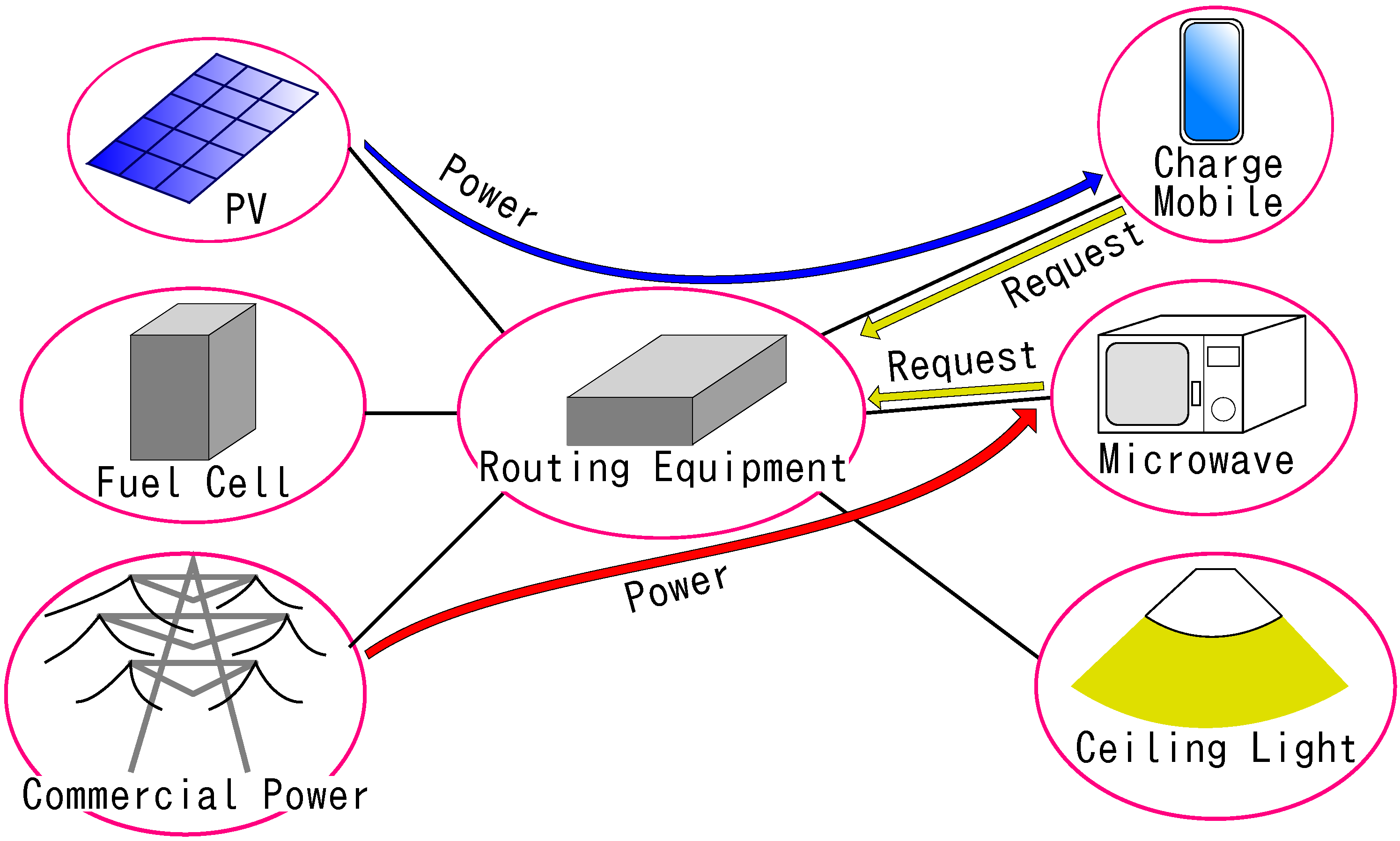
Figure 1 depicts the conceptual diagram of the AC power distribution system in home. House service cables from power sources are connected into power routing equipment. Indoor network cables are also linked with the routing equipment. Firstly, when the user wants to use an electric appliance, the appliance sends a request for supply of power to the router. The request consists of the amount of necessary power, quality of power required, ID number of the appliance, priority of the requests, and so forth. The routing equipment receives the information and selects a suitable power source correspondingly. Then the equipment configures the route from the suitable source to the load. Finally, it supplies power concurrently with its information, for example, destination appliance, the amount of power, and the quality of power. The equipment collects all the information from sources and loads. It implies that this system is centrally managed. When batteries built in mobiles or laptops are charged, the supplied power is relatively low quality. On the contrary, commercial power of high quality is preferentially applied for important loads or equipment, like medical instruments, which do not have the tolerance to momentary voltage drop. The routing equipment chooses to utilize renewable and natural power sources as much as possible.
Figure 1.
AC power distribution system in home.
Figure 1.
AC power distribution system in home.
There is also a possibility for the user of setting the maximum amount of whole consuming energy for a given period. When the demand of electricity is likely to exceed the maximum value, the supply to low-priority load is shut until consuming energy drops below the threshold. For instance, air conditioners and heaters consume large amount of power at start-up. Microwave oven also needs much electricity. When this equipment is in use, charging batteries may be stopped or ceiling lights turned off for a while in order to reduce total power consumption. Along the concept of power management, the power flow can be optimized to adjust the demand to the supply.
2.2. AC Power Routing Apparatus
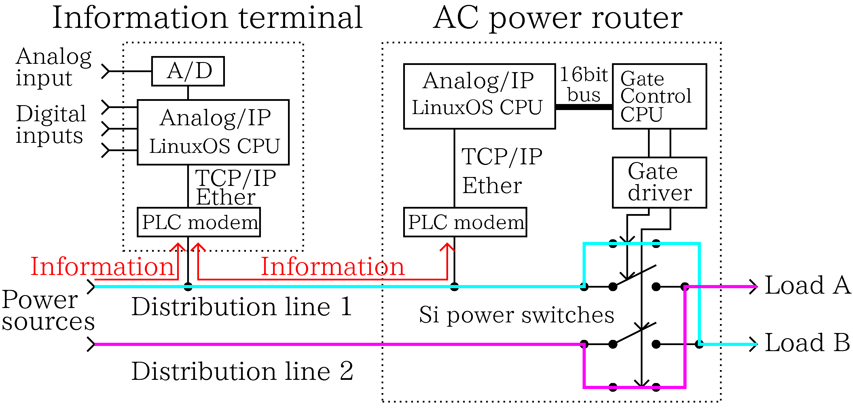
The routing equipment is divided into two components in the proposed system according to their function. One is an information terminal. The other is an AC power router.
Figure 2 shows the schematic diagram of the system and
Figure 3 is a photograph of the developed AC power router and the accompanied information terminal. Each of the components includes a PLC modem and the microprocessor (CPU, Renesas Electronics; SH7619) in which Linux OS is installed. The information terminal also has digital and analog I/O ports as additional communication gateway except for the PLC modem.
Figure 2.
Schematic diagram of AC power routing system.
Figure 2.
Schematic diagram of AC power routing system.
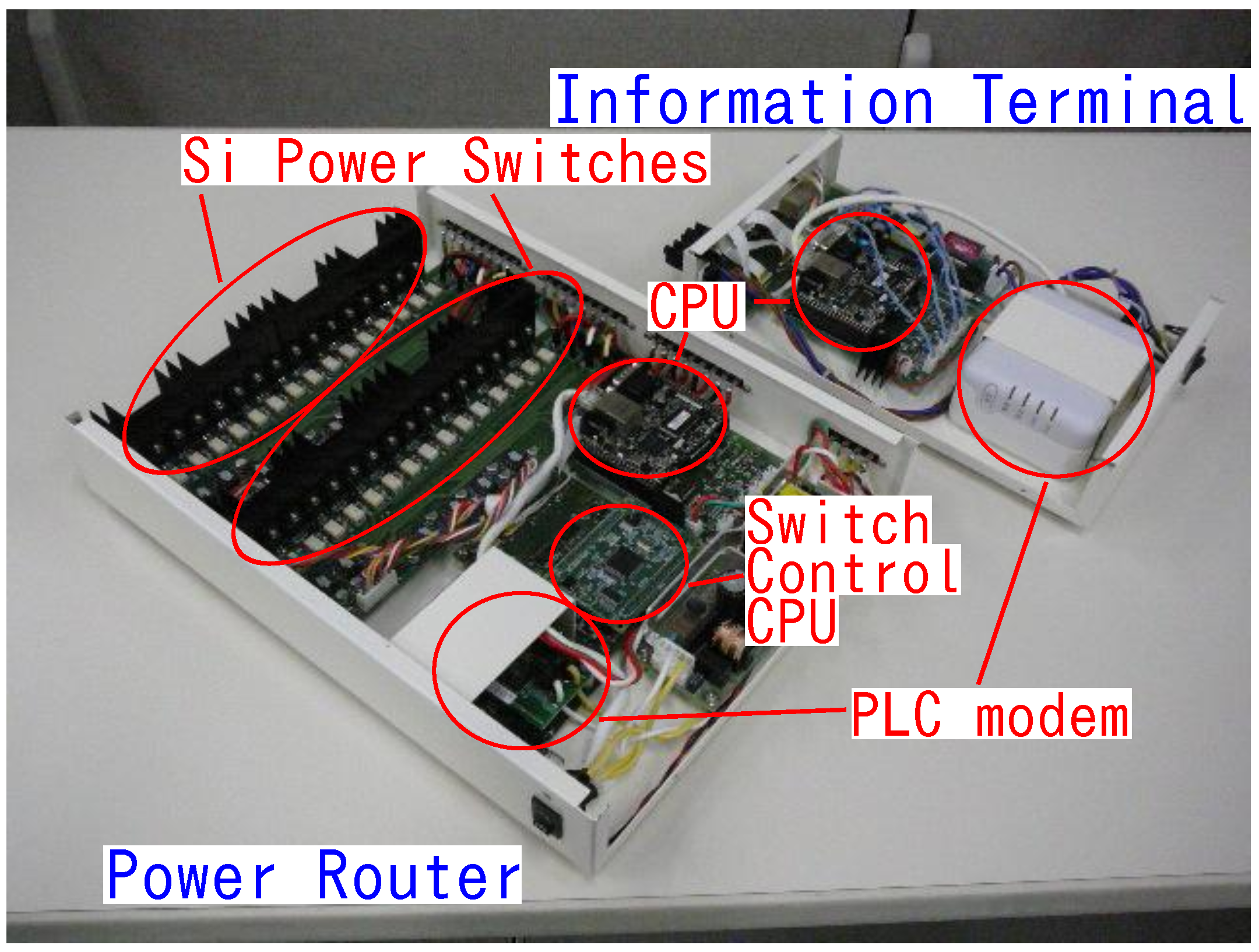
Figure 3.
Photograph of a prototype AC power router and information terminal.
Figure 3.
Photograph of a prototype AC power router and information terminal.
The terminal gathers information from both power sources and loads. The CPU decides the optimal combination of the source and the load according to the information on supply and demand of power. The information of the source-and-load pair is transferred to the power router via PLC.
The AC power router receives information about source-and-load pairs. The router has inputs of power and information and outputs of power. It possesses semiconductor power switches to change circuit topology. Here, silicon (Si) MOSFETs (Toshiba; 2SK3935, 450 V, 17 A) are applied as switches because a number of uniform and optimized SiC devices are not available at this moment. The devices are selected to confirm the possibility of the proposed system. The router is equipped with extra CPU (Renesas Electronics; H8/3052F) to control these switches. The switches are split into two groups of switches as shown in
Figure 3. The maximum number of operable sources and loads can be expanded by adding another group. In
Figure 3, two inputs and four outputs are considered for illustration.
3. Experiments
An experiment of power transmission was carried out using the existing technology for proof-of-concept validation.
Figure 4 depicts experimental setting of the AC power routing. For simplicity, the inputs and outputs of this setup are limited to two sources and two loads although the router has four output terminals. We exclude inductive loads such as motors from consideration. Most home appliances are equipped with switched power supply with power factor correction (PFC) circuit, of which input current keeps in phase with the input voltage. Then resistive loads are only considered here, without loss of generality. In this paper, Si MOSFETs are applied as power switches. Even if SiC semiconductor switches are adopted, the system configuration of a circuit is fundamentally the same as the circuit under test. To avoid the confusion of discussions in system design and circuit implementation of devices, we are focusing on the operation of system.
Figure 4.
Schematic diagram of configuration of experiment.
Figure 4.
Schematic diagram of configuration of experiment.
The power rating of the system depends on the rating of power switches. Therefore, we can improve the maximum operable power by replacing power switch units. Si power switches of 450 V, 17 A are adopted in the experiment under assumption of applying 100 V to the system. Hence, the router can switch at most 1.7
in the case.
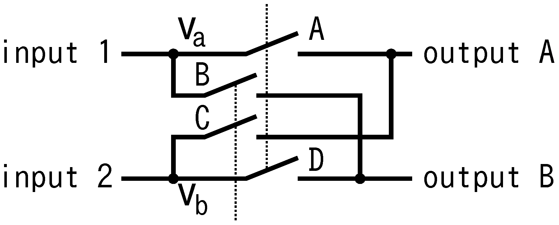
Figure 5 shows circuit exchange switches. While switches A and D are closed, switches B and C are opened, and vice versa. Circuit topologies are changed at the instant when
equals to
in order to suppress short current and prevent switches from breaking down by surge voltage. We call this technique of determining switching timing “equipotential switching”.
Figure 5.
Schematic diagram of circuit exchange switches.
Figure 5.
Schematic diagram of circuit exchange switches.
A computer (PC) is connected with distribution line via a PLC modem and the information terminal via serial communication cable during the experiments. The PC sends switching commands to the information terminal via serial communication. Then the terminal sends information to the power router via PLC. The router changes connection of the circuit. In practice, however, the information terminal operates according to the input of digital I/O port, analog I/O port, or information sent via PLC. Therefore, the PC is not essential in practical use. Here, it produces simulated information from appliances and monitors the status of the power router.
Two power sources are used in the experiments. One is a 100 V/60
commercial voltage source. The other is from photovoltaic (PV) panels. DC power generated by PV panels is converted into 100 V/60
AC voltage by a power conditioner. The power conditioner can drive both independently from commercial grid and interconnected with the grid. It operates in stand-alone mode in the experiments. In this case, the output voltage of the power conditioner has slightly different frequency from the commercial voltage source. The difference in frequency is less than 0.01
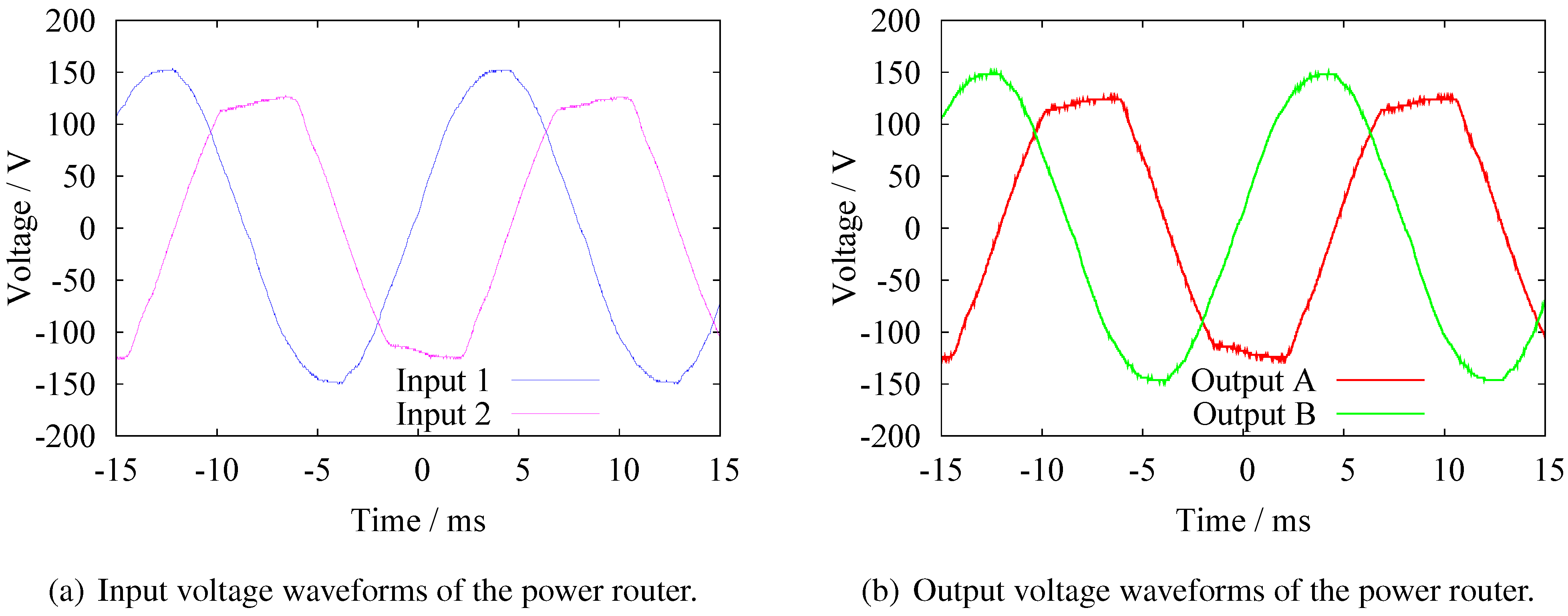
. It changes depending on the power generated by the PV. The more power the PV generates, the faster the frequency becomes. It depends on the self-operating control scheme of the conditioner. The initial phase of voltage is also determined voluntarily. An example of input voltage waveforms are shown in
Figure 6(a). Input 1 (blue line) is the commercial voltage and input 2 (purple line) is the voltage of the power conditioner. The phase of voltage of the power conditioner is different from that of commercial source, and the waveform of power conditioner is distorted particularly at the peak.
Two incandescent bulbs of 30 W are used as resistive loads A and B, connected to outputs A and B, respectively.
Figure 6(b) shows voltage waveforms at output terminals A and B under the connection pattern (b) in
Table 1. The red line indicates output A and the green line indicates output B. Comparing with
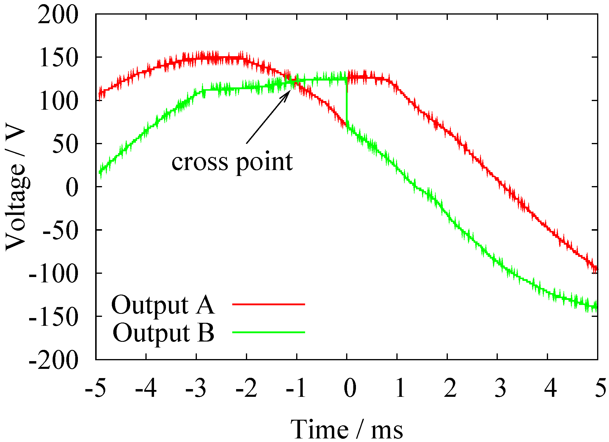
Figure 6(a), the same waveforms appear to output waveforms. The transition from the pattern (a) to the pattern (b) is shown in
Figure 7. Although the circuit is designed to operate switches soon after cross point is detected, a delay of 1.05
appears. Around 50 V of difference in voltage between two inputs at the instant of switching is induced due to the delay. This delay may be caused by processing time of switch control CPU. In spite of the voltage difference, circuit exchange is achieved successfully under the configuration.
Figure 6.
Input and output voltage waveforms of power router.
Figure 6.
Input and output voltage waveforms of power router.
Table 1.
Connecting pattern of inside power router.
Table 1.
Connecting pattern of inside power router.
| Pattern | Input |
| 1 | 2 |
| (a) | Output A | Output B |
| (b) | Output B | Output A |
Figure 7.
Output voltage waveforms of the power router at the instant of switching.
Figure 7.
Output voltage waveforms of the power router at the instant of switching.
The efficiency of the router for sinusoidal input voltage is estimated from the measurement of input and output power under steady state with a power meter (HIOKI; 3193). Measured input voltage, current, power and those of output are shown in
Table 2. The efficiency of the router is calculated to be 99.67 %.
Table 2.
Measured input and output voltage, current, and power.
Table 2.
Measured input and output voltage, current, and power.
| | Input | Output |
|---|
| Voltage | 104.31 V | 104.13 V |
| Current | 0.2359 A | 0.2361 A |
| Active Power | 24.78 W | 24.70 W |


