1. Introduction
Today, from an environmental viewpoint, it has become extremely important to use wind power for electrical energy generation. Wind farms, which are areas with many wind turbines used for generating electric power, have been established in many countries. It is important to ensure continuous operations of these wind farms so that the power supply can be constant and reliable. Hence, grid codes have been established in many countries to avoid unexpected wind-farm disconnections, which can perturb the stability and operations of the electrical network. Sudden wind-farm disconnections occur because of dips in transitory parameters such as voltages. In
Section 2 of this article, it will be seen that according to the Spanish grid code requirements [
1,
2], wind-generators must not only not have any disconnections, but they must also deliver reactive powers to the electrical network during any disturbances. The Spanish grid code also indicates the maximum allowed reactive power consumptions in the perturbation and the standard IEC 61400-21 [
3] specifies that the mentioned reactive power must be the fundamental-frequency positive-sequence reactive power (FPRP), established by several theories [
4,
5,
6] and included in the IEEE Standard 1459 [
7].
The main magnetic field of the wind generators under any voltage conditions is defined on the basis of FPRP (
Q+). This magnetic field governs the voltages and electromechanical stability of these machines in the normal operation, but when voltages are unbalanced and/or distorted, as occurs during voltage dips, the magnetic field is deformed and operation of the wind generators cannot be explained only by means of FPRP. New reactive power components corresponding to each involved phenomena must be considered jointly with the FPRP to accurately analyze operation of wind turbines subjected to voltage dips. Several reactive power formulations are known in the technical literature and could be used for this purpose. Delayed voltage (DV) reactive power and CPC fundamental reactive power, described by Czarnecki in [
8], are used in
Section 3 to obtain other reactive power components which can help us to analyze the magnetic field of the wind generators in the case of unbalanced and distorted voltages. Non-fundamental reactive power (
QH) is established by comparing DV reactive power and CPC fundamental reactive power. This reactive power component defines the distorted magnetic field superposed on the main magnetic field of the wind generators as a result of the voltage distortion. Fundamental negative reactive power (
Q−) is obtained as the difference between CPC fundamental reactive power and FPRP. Last reactive power characterizes the reverse magnetic fields superposed to the main magnetic field, which are caused by the voltage unbalances and disturb wind generators operations. Negative reactive power (
Q−) is decomposed into the reactive powers due to the reactive loads (
Qr−) and caused by the imbalances (
Qu−). Also, in
Section 3, FPRP is divided into two reactive power components [
9,
10,
11]: due to the reactive loads (with balanced voltages),
Qr+, and caused by the imbalances,
Qu+. These decompositions can be very useful to analyze wind generator operations and to explain some of their poor workings, because comparison between these reactive power components shows the variation of the reverse and the main magnetic fields during unbalanced voltage dips and, thus, they inform about the re-magnetization or demagnetization of the wind generators in such transitory phenomena. Instantaneous p-q theories established by Akagi [
12] and others [
13], widely used for controlling the electronic converters of the wind turbines, was not considered in this study because the well founded objections expressed by Czarnecki in [
14,
15].
The question is finally where the above defined reactive powers must be registered in order to measure the magnetizing reactive power and, thus, the magnetic field in the doubly fed induction generators. It is known from [
16] that when a sudden voltage dip occurs and the currents reach dangerous values, the crowbar system is activated; to avoid the shaft-speed from exceeding the critical value. Doubly fed induction generators operate under such conditions as a squirrel-cage induction generator and, thus, the stator reactive power approximately coincides with the magnetizing reactive power, which defines the magnetic field and, thus, the operation of these machines. This conclusion was applied in
Section 4 to analyze operation of one actual wind generator subjected to voltage dips. Practical measures were registered by a Fluke 1760 three-phase power quality recorder and, then, these data were processed by the SIMPELEC software [
17] to obtain the reactive powers.
4. Practical Experiences
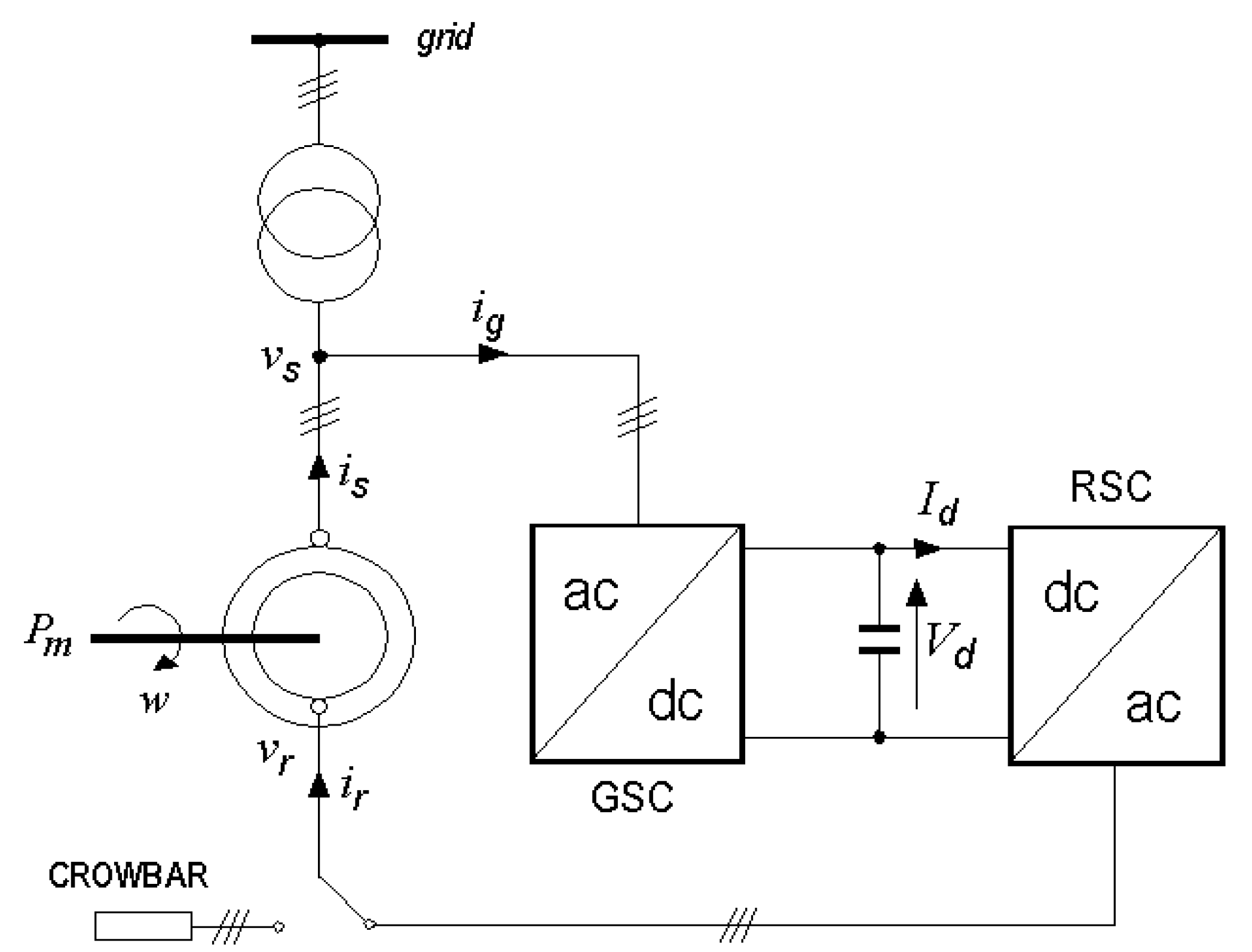
A remarkable two-phase voltage dip was considered for analyzing the operations of one actual wind generator. The study is made through the observation of the magnetizing reactive power, since this quantity determinates the magnetic field of the wind generators. In the normal operation, the magnetizing reactive power of the doubly fed wind generators is related with the reactive power measured at the stator and varies inversely with the slip(s) of these machines. But, in presence of voltage dips, the crowbar is applied to the rotor windings (
Figure 4) and, thus, wind generators operate as the squirrel-cage induction generators [
16], where stator reactive power approximately is equal to the magnetizing reactive power. Hence, for the experimental analysis showed in this section, the reactive power formulations expressed in the previous section are applied to the data measured at the stator.
Figure 4.
Doubly fed induction generator and crowbar system.
Figure 4.
Doubly fed induction generator and crowbar system.
Stator of the double-fed induction generator is directly connected to the grid through a power transformer (
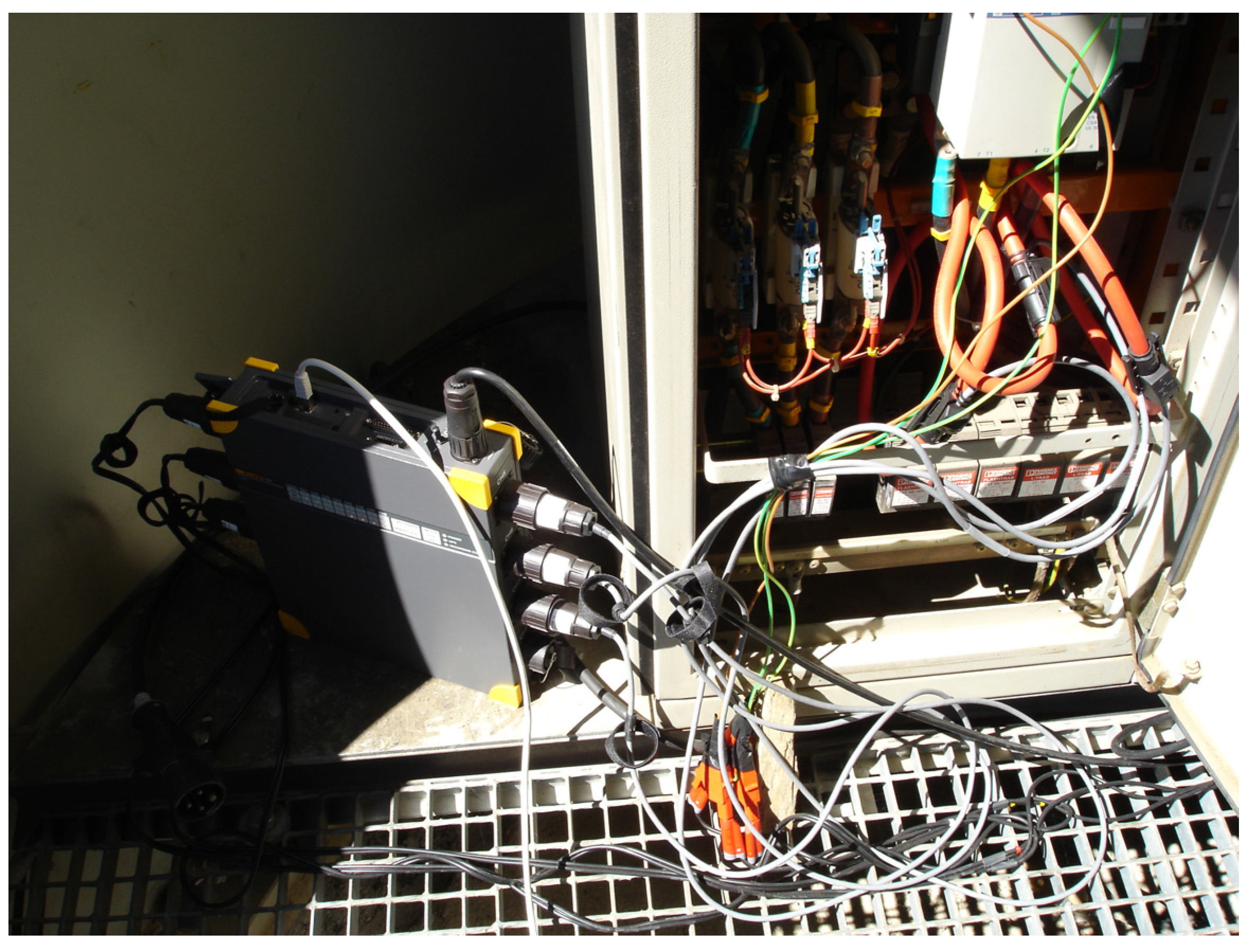
Figure 4), and they have the following electrical rated characteristics: power = 660 kW and line-to-line voltages = 690 V. The data were recorded using the power quality recorder Fluke 1760 (
Figure 5) and subsequently processed by the SIMPELEC software [
17].
Figure 5.
Connection of the Fluke 1760 three-phase power quality recorder.
Figure 5.
Connection of the Fluke 1760 three-phase power quality recorder.
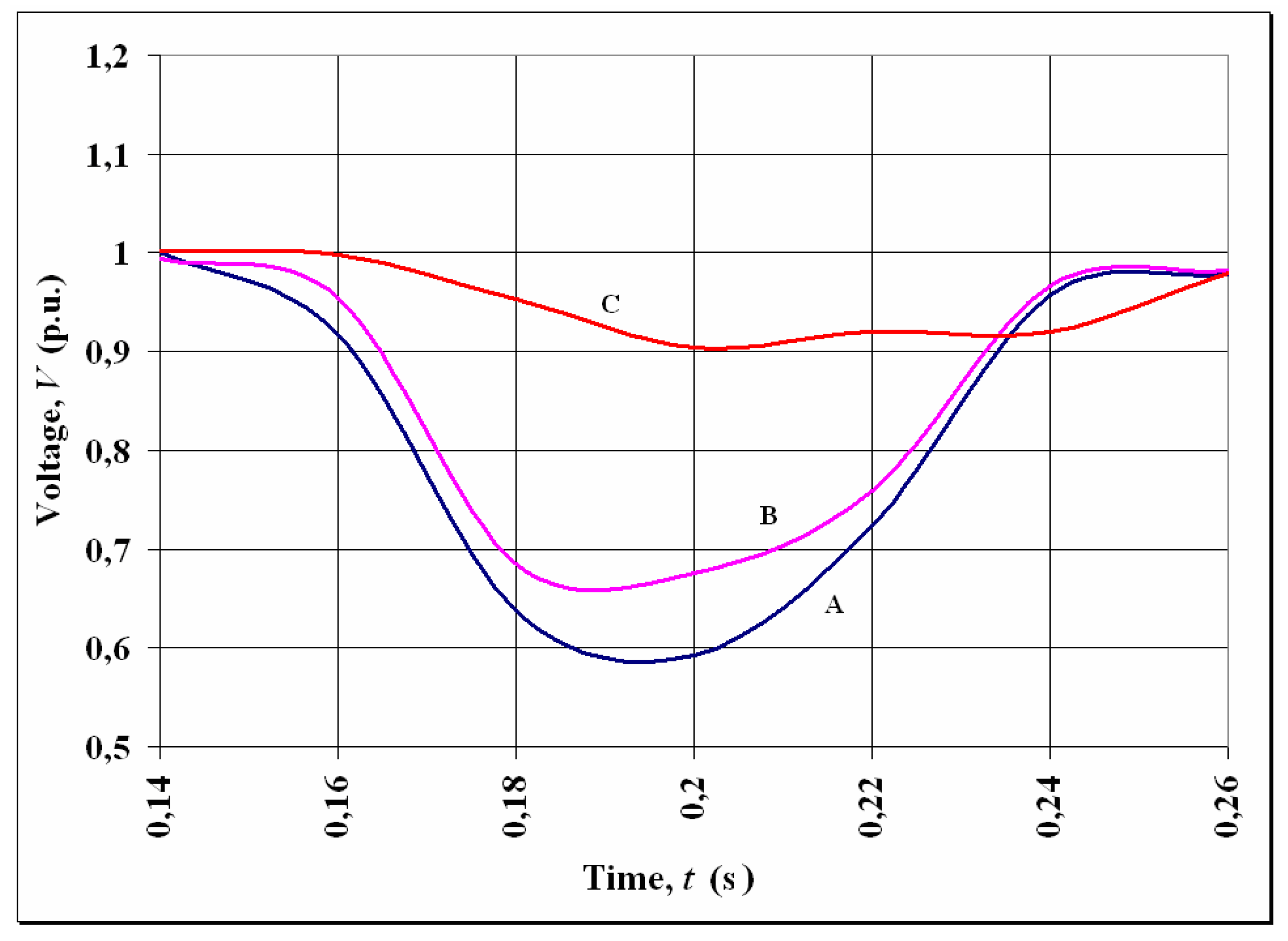
Figure 6 shows an 80-ms two-phase registered voltage dip. The voltages of the A and B-phases decreased to less than 40 and 30%, respectively, of their rated values, while the C-phase voltage did not decrease to less than 10%; hence, the failure affected only two phases (according to the voltage dip definition included in the Std. UNE-IEC/TR 61000-2-8 IN [
3]).
Figure 6.
Two-phase voltage dip, RMS voltages (p.u.).
Figure 6.
Two-phase voltage dip, RMS voltages (p.u.).
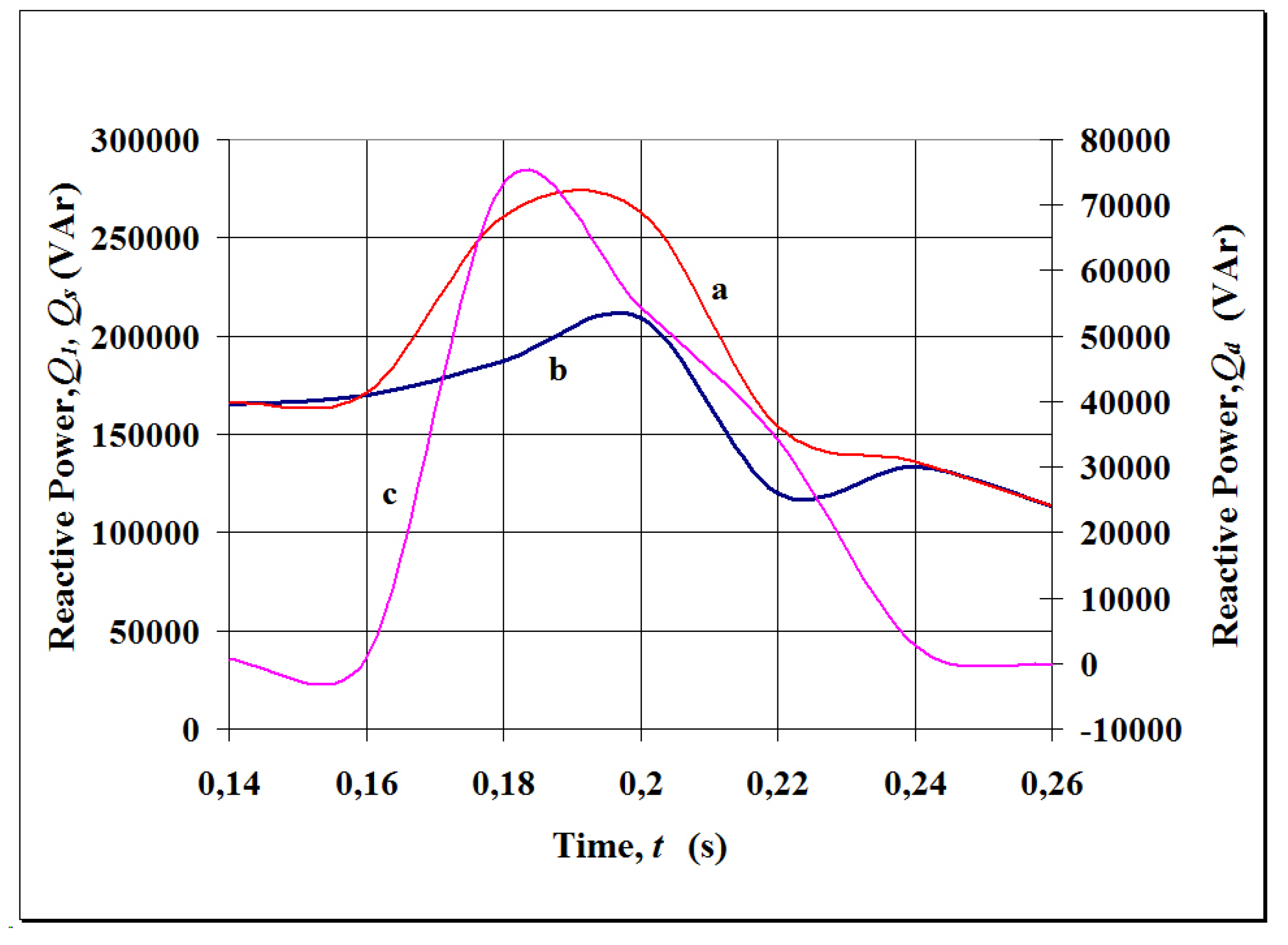
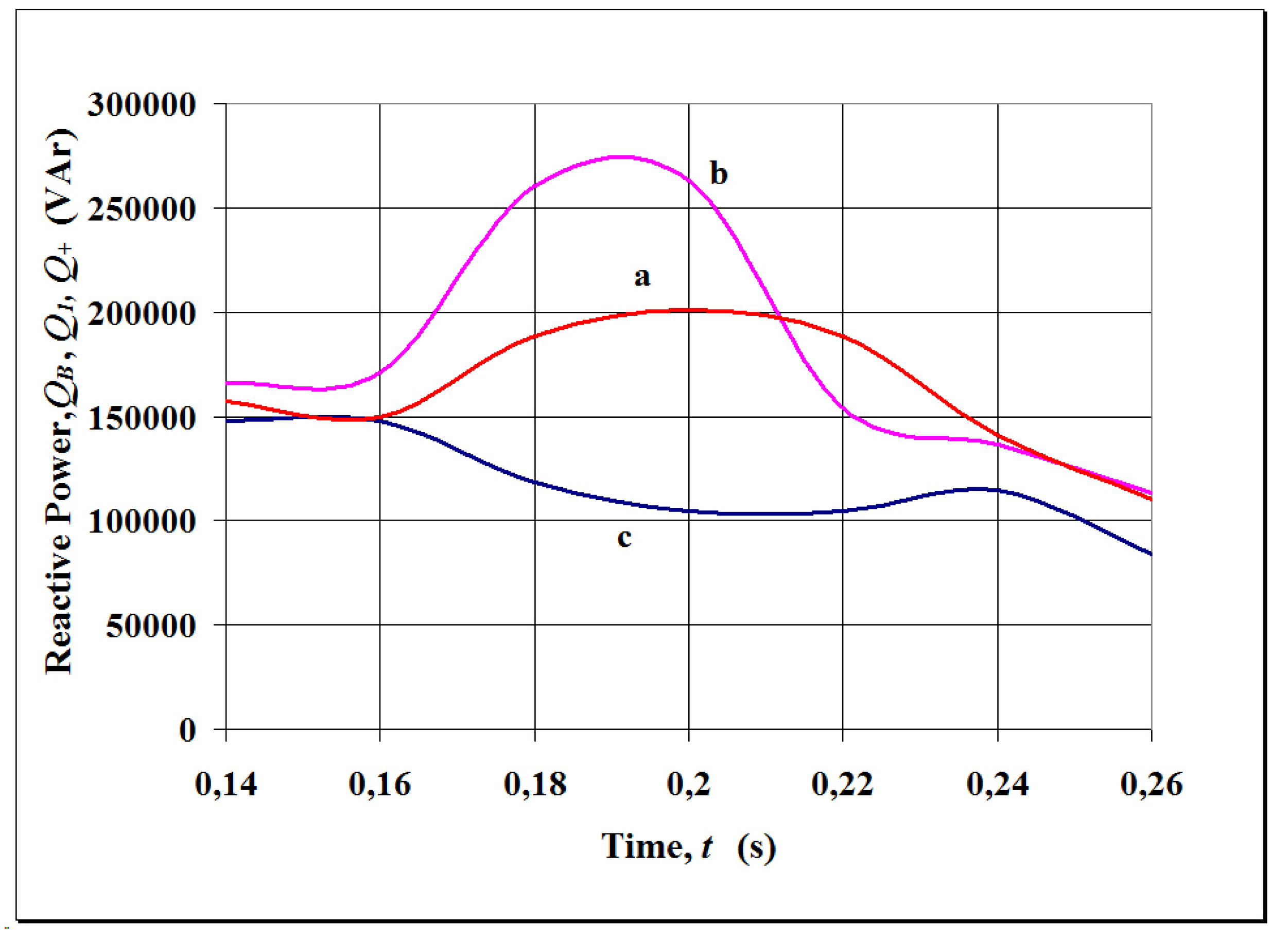
The reactive powers obtained by DV method, Czarnecki’s CPC theory, and FPRP formulations are shown in
Figure 7. These reactive powers were supplied by the wind generator (positive sign, according to definition included in [
3]). DV and Czarnecki’s reactive powers had similar values before and after the perturbation (165 kVAr before the beginning of the voltage dip and 120 kVAr after the clearance of the voltage dip); however, during the perturbation, the three analyzed reactive powers had different values. Czarnecki’s reactive power had maximum values of 275 kVAr, while FPRP reduced (
Figure 7); but, since no FPRP consumptions occurred during the voltage dip period, the reactive power requirements specified by the Spanish grid code were verified.
Notice that only the values of FPRP are applied to verify the accomplishment of the Spanish grid code requirements; however, other reactive powers could be used to analyze operation of the wind generators.
Figure 7.
Reactive powers: (a) Delayed Voltage, (b) Czarnecki, (c) FPRP.
Figure 7.
Reactive powers: (a) Delayed Voltage, (b) Czarnecki, (c) FPRP.
The Delayed Voltage (DV) reactive power (
Q) is obtained through all voltage and current components, while Czarnecki’s CPC fundamental reactive power (
Q1) is expressed by the voltages and currents of fundamental-frequency. Measured values of
Q were different that those of Czarnecki’s (
Q1) during the perturbation (
Figure 7). These reactive powers,
Q and
Q1, define different magnetic fields, which rotate at different speeds and cause some distinctive effects. The difference between
Q and
Q1 has been called in this paper as the non-fundamental reactive power (
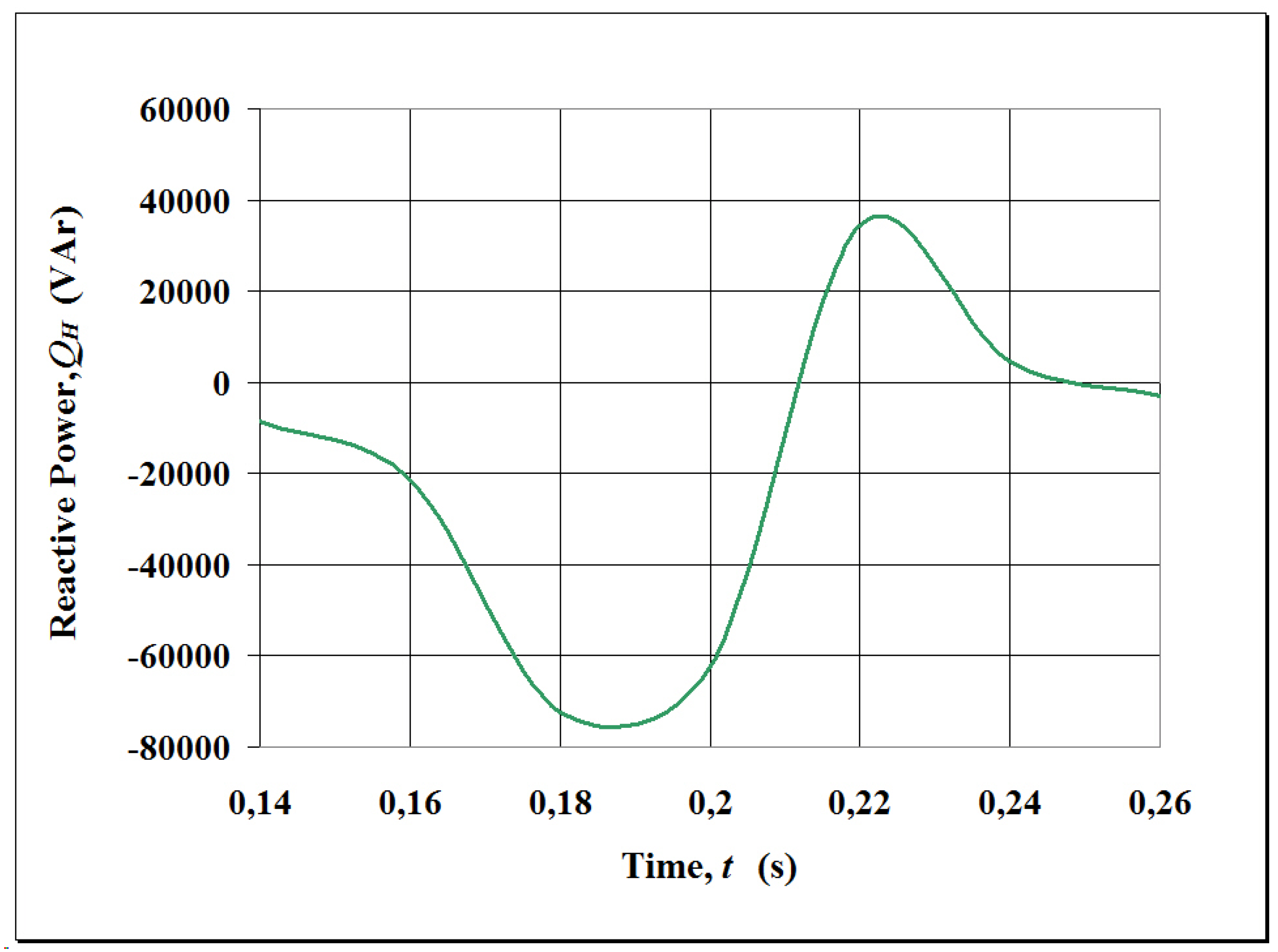
QH), which defines the harmonic magnetic fields in the wind generator, originates harmonic electromagnetic forces and torques and generally decreases the generator efficiency. Non-fundamental reactive power was absorbed by the wind generator in the first half of the voltage dip, and the maximum value was 75 kVAr (
Figure 8). During the second half of the voltage dip, non-fundamental reactive power was supplied by the wind generator; the maximum value was 35 kVAr. The sign, positive or negative, of the values of
QH do not provide fundamental information about the magnetic field defined by this reactive power. The magnetic fields corresponding to each individual harmonic have significance; the speed and direction of rotation for each harmonic magnetic field is determined by its own frequency and its sign (positive or negative) indicates the direction of the electromagnetic forces and torques. Existence of the non-fundamental reactive power informs about the deformation of the magnetic field and its value only should be considered as a reference about the distortion importance. In the present experience, non-fundamental reactive power reached comparable values with the fundamental positive-sequence reactive power (
); this implied that harmonic magnetic fields strongly perturbed the operation of wind generators during the unbalanced voltage dip.
Figure 8.
Non-fundamental reactive power.
Figure 8.
Non-fundamental reactive power.
Czarnecki’s CPC fundamental reactive power (
Q1) and FPRP (
Q+) had great differences during the voltage dip period (
Figure 7,
Figure 9 and
Figure 11). This is because the effect of the voltage unbalances, which determinate the negative reactive power (
Q−), whose evolution is showed in
Figure 10a.
Figure 9.
Czarnecki’s CPC fundamental reactive powers: (a) total, (b) due to reactive loads, (c) caused by imbalances.
Figure 9.
Czarnecki’s CPC fundamental reactive powers: (a) total, (b) due to reactive loads, (c) caused by imbalances.
This reactive power component defines the reverse magnetic field, which rotates with the same speed and opposite direction that the main magnetic field of the wind generator and creates reverse electromagnetic forces and torques. Since
Q− reaches maximum values of 165 kVAr (
Figure 10a) and FPRP (
Q+) is 100 kVAr, the wind generator was subjected in this experience to large electrodynamic forces, due to the voltage imbalances, during the voltage dip. However, in spite of
Q− >
Q+, reverse torques were less than direct torques, since values of these electromagnetic torques are inversely proportional to 2-s and s, respectively, where s is the slip of the wind generator.
In the other hand, decomposition of
Q− and
Q+ into two components (
Figure 10 and
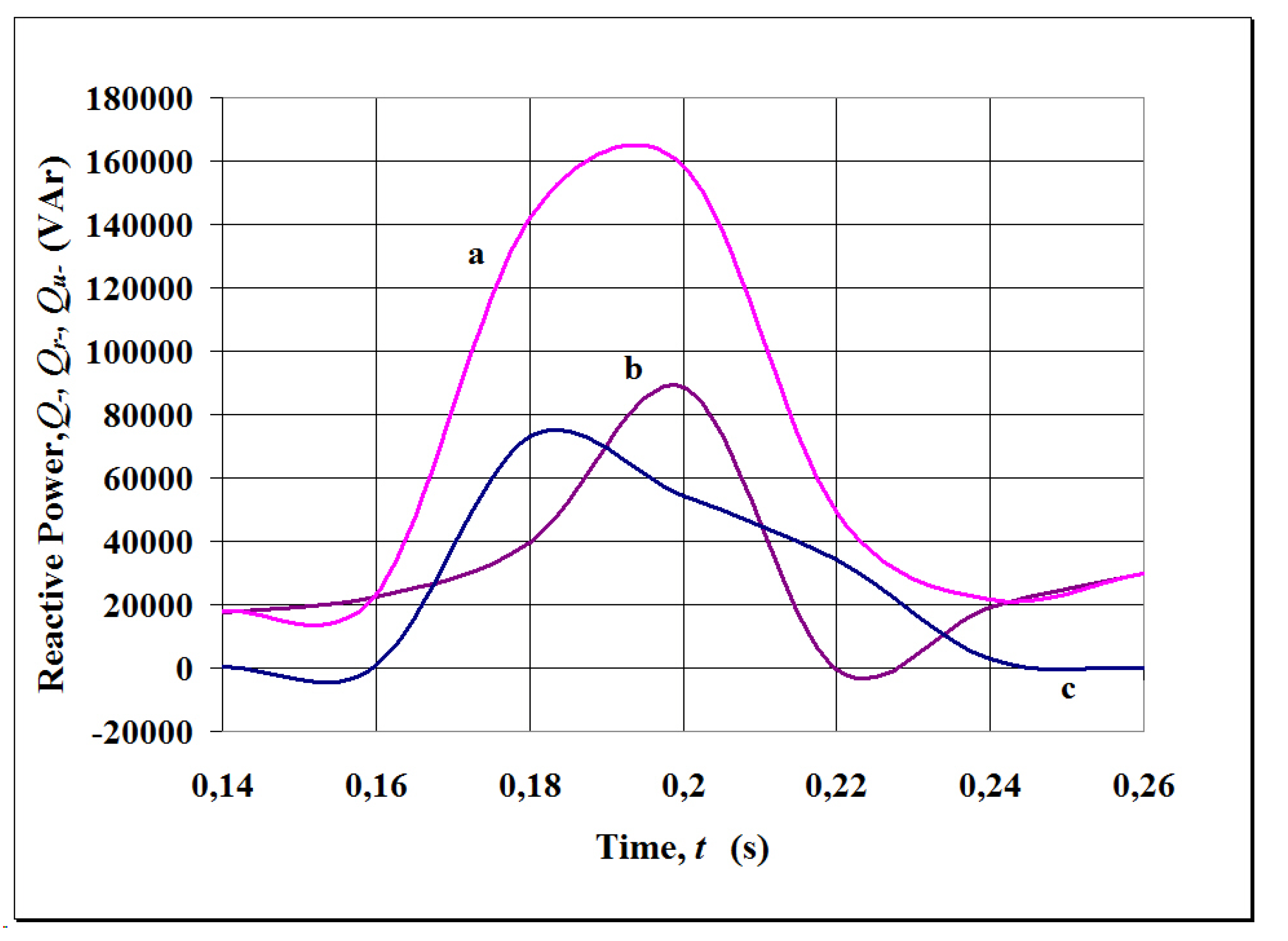
Figure 11, respectively) provides additional information, which can help us to know the causes of these large reverse forces and magnetic fields. In the present experience, the negative reactive power component due to the reactive loads (
Qr−) and the negative reactive power component caused by the voltage unbalances (
Qu−) have comparable values during the voltage dip (
Figure 10), but
Qu− is greater than
Qr− at the beginning and in the end of the voltage dip. This one implies the reverse torques caused by the voltage unbalances have more importance during these periods than the reverse torques due to the reactive loads, and the contrary occurs in the middle of the voltage dip where
Qr− >
Qu−, in this experience (
Figure 10). Anyway, negative reactive power components are responsible of poor wind generator operations.
Figure 10.
Negative-sequence reactive powers: (a) total, (b) due to reactive loads, (c) caused by imbalances.
Figure 10.
Negative-sequence reactive powers: (a) total, (b) due to reactive loads, (c) caused by imbalances.
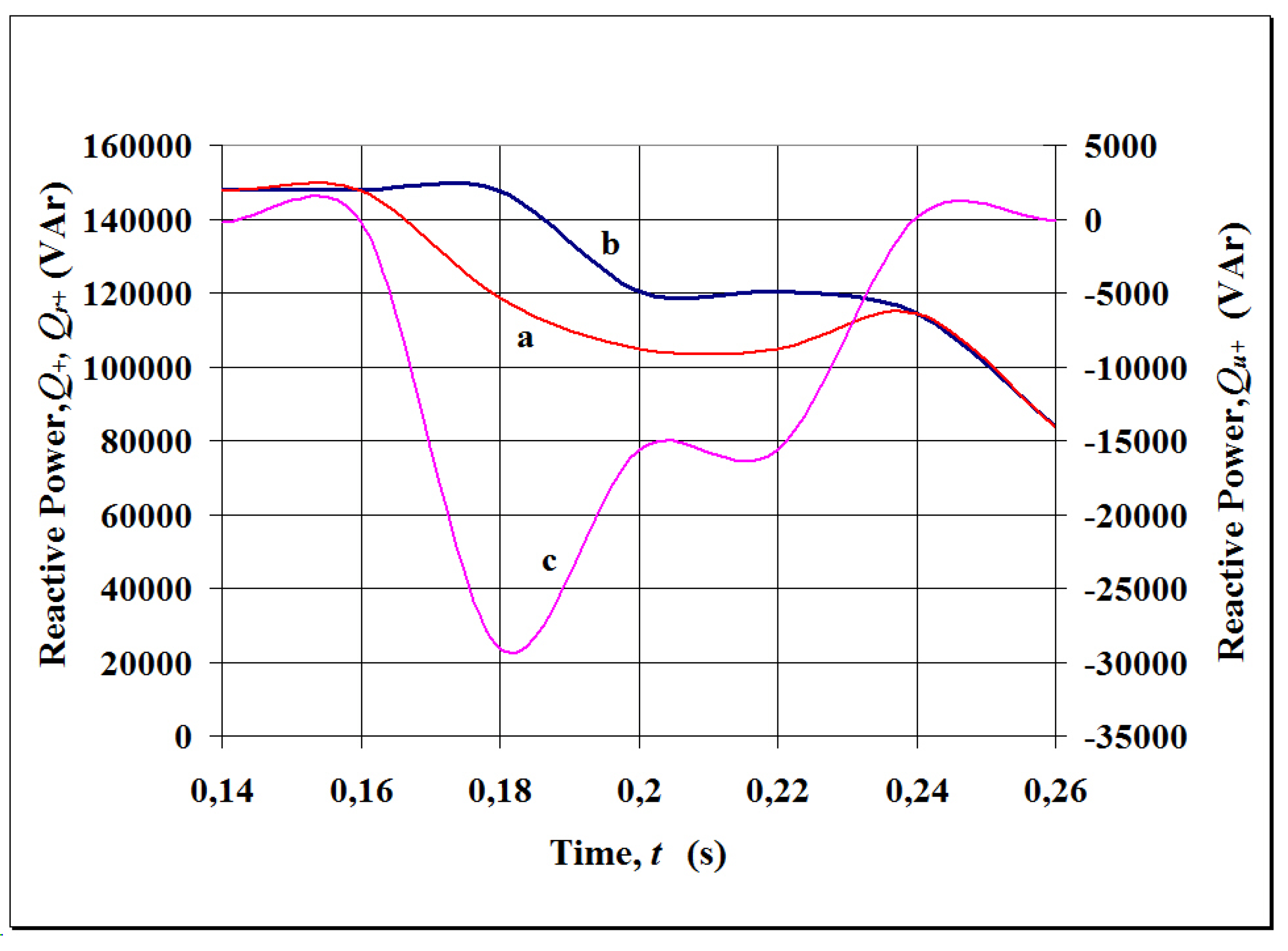
Figure 11 shows that the FPRP (
) decreased during the voltage dip as a result of the existence of a reactive power component caused by the unbalances (
), which is absorbed by the generator (Figure 11c) and partially compensates the FPRP due to the reactive loads (with balanced voltages,
Qr+). This reduction reached a third part of the fundamental positive-sequence reactive power (
), thereby causing a sudden demagnetization of the generator when the main magnetic field (created by
) decreased. As a result, the relative importance of the negative-sequence magnetic fields that were established by
(
Figure 10) increased.
Figure 11.
Positive-sequence reactive powers: (a) total, (b) due to reactive loads, (c) caused by unbalances.
Figure 11.
Positive-sequence reactive powers: (a) total, (b) due to reactive loads, (c) caused by unbalances.
In conclusion, the operation of the wind generator was considerably perturbed during the two-phase unbalanced voltage dip and this perturbation can be explained by using the magnetic fields defined by the magnetizing reactive powers. The primary reasons for the poor generator operations are as follows: (a) unbalanced voltages and loads that decreased the magnetic field of the main generator (created by ) and increased the reverse magnetic field (due to ), and (b) the distorted voltages and loads that caused harmonic magnetic fields with different speeds (some with different rotation senses) than the main magnetic field. However, wind generator could support the voltage dip without disconnection.
5. Conclusions
Fundamental-frequency positive-sequence reactive power (FPRP) included in the IEEE Standard 1459 and recently proposed by the IEC 61400-21:2008 and other wind farms standards should be supplemented with other reactive power formulations in order to obtain a complete and detailed analysis of the wind-generator operations in unbalanced and/or non-sinusoidal voltage conditions. This is because the main magnetic field of the wind generators, defined by the FPRP, is perturbed by the magnetic fields originated by voltage imbalances and distortions, when subjected to voltage dips.
For this purpose, the use of the non-fundamental and the negative-sequence reactive powers, established in this paper by comparing Delayed Voltage reactive power, Carnecki’s CPC fundamental-frequency reactive power and FPRP, and the decomposition of Czarnecki’s and FPRP into two components, due to the reactive loads and caused by the imbalances, provide additional information about wind generator operation in presence of voltage perturbations. The non-fundamental reactive power characterizes the presence of harmonic magnetic fields, while negative-sequence reactive power defines fundamental reverse magnetic fields. These magnetic fields perturb the main magnetic field and thereby explain the poor operations of wind generators and failures caused in the presence of unbalanced and distorted voltage dips. Also, it was observed on the application example that FPRP components, due to the reactive loads and caused by the imbalances, could have the same or opposite sign and, thus, increases or decreases of the main magnetic fields, responsible of the re-magnetization or demagnetization, respectively, of the wind-generators, could be otherwise explained.

